Chuck
-
Posts
9,725 -
Joined
-
Last visited
Content Type
Profiles
Forums
Gallery
Events
Everything posted by Chuck
-
 Not Really. Its not a dead project at all. Its just far back on the list. Thank you for asking. Chuck
- 16 replies
-
- 13
-

-
- Sophia Rose
- Block Island cowhorn
- (and 1 more)
-
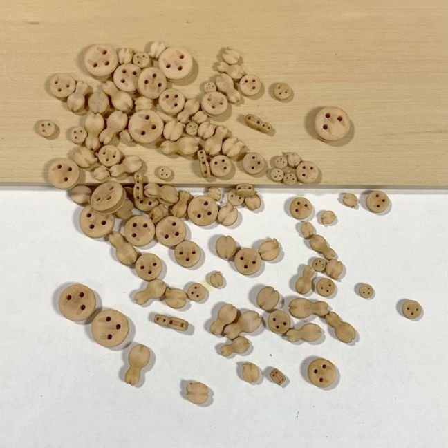
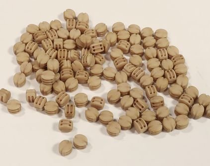
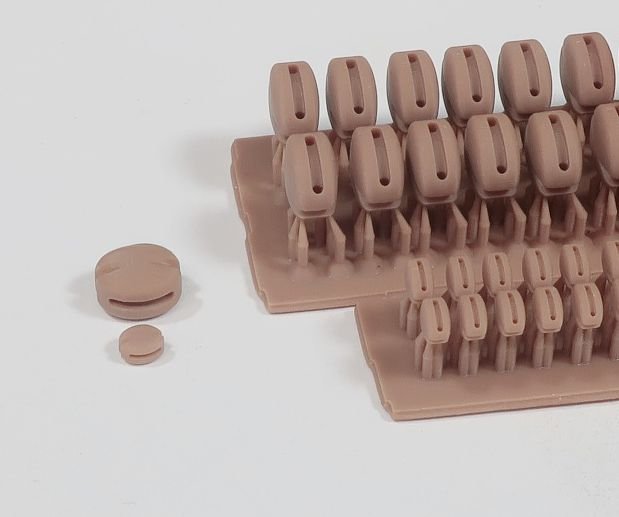
Deadeye test in the "English Boxwood" color along with a test of fiddle blocks and shoulder blocks. Keep in mind these pics are just taken with my phone. They look pretty good in reality.
-
Wrong sheet you have there…thats chapter two. Those parts are all for the cant frames. They shouldnt even be out of the sheet yet. I fear you have mixed up all of your parts. literally that part 8 is on the sheet with the keel parts from chapter one. The long keel sections for beneath the keelson. Again 5/32” thick. If you built your keel then you have those parts. A little tip….dont even touch the parts bag for chapter two until you are done with chapter one. That is a recipe for disaster.
-
Sheet "D" with the keel parts. They are 5/32" thick.
-
Its still too new to me to know that. I pretty much still fumbling around.
-
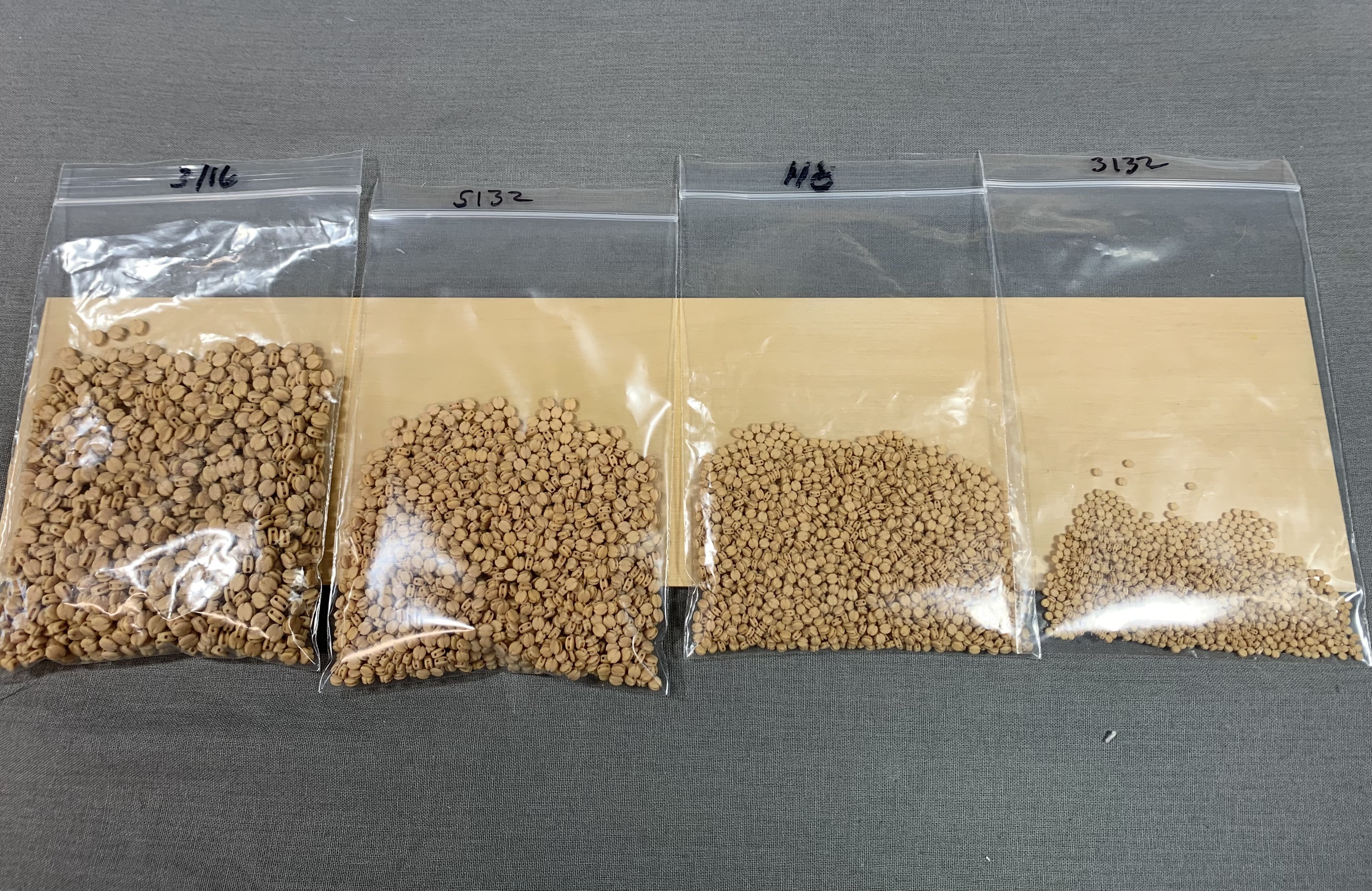
Production has begun. 3/16” singles…

-
Send me your address info via pm and i will mail them to you. chuck
-
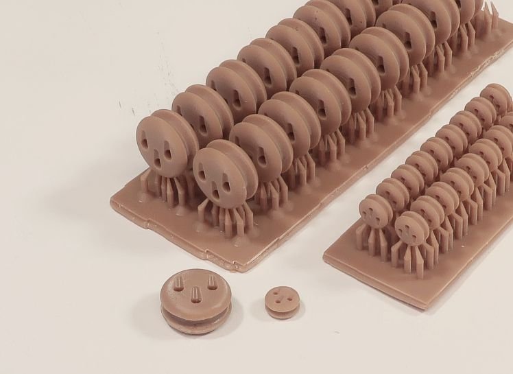
OK slight confession....the blocks you see me working on above are not boxwood. I am working on a speedier alternative. The tricky part is making them look like wood. This will also be a much much cheaper alternative. These blocks are all 3d printed. No painting required...they will come like this straight out of the bag. I have the boxwood or natural blocks all figured out and they look really good. I hope you agree. I just need to get the darker shade chosen. Color and finish is the tricky part of this. Clue blocks, sheet blocks, sister blocks, violin blocks, hearts deadeyes.....the possibilities are endless. Chuck Early tests....good prints but bad resin. It wouldnt dye the correct color and was too shiny.
-
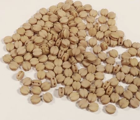
Yes it was just a bad photo...sorry. Here is a better one. These are so tough to photograph for whatever reason. These are the finished blocks. Production will resume soon. But first to enjoy the fourth!!!
-
Very Nice progress.
-
Thank You!!! There is now a small quantity available in my store. They are on the Winnie page. Chuck
-
Give me a few days and I will make about a dozen packages for the Winnie. I will post when they are ready and available in my store.
-
It doesnt matter…whatever is more comfortable.
-
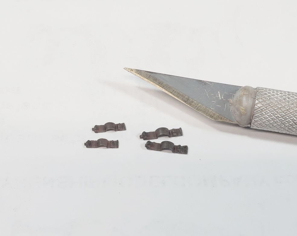
It seemed to work out just fine....But I will let you guys be the judge. These are so small. But they will save so much time. They are very difficult to photograph being black....ish. These take a while to cut so please comment on yea or nay. I dont want to make a bunch and then nobody buys them. I would say $10 per set to cover all the guns on the Winnie.
-
But.....I will give it a try...what the hell!!!
-
I wish I could. I dont think I can make them that small. The ones for speedwell are about as small as I can make them. Chuck
-
Multiple passes and the are made of acrylic.
-
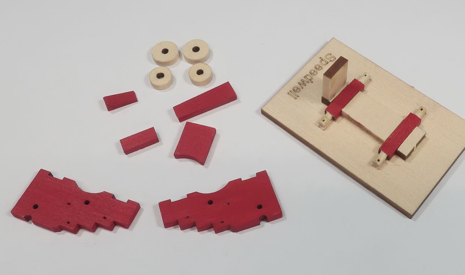
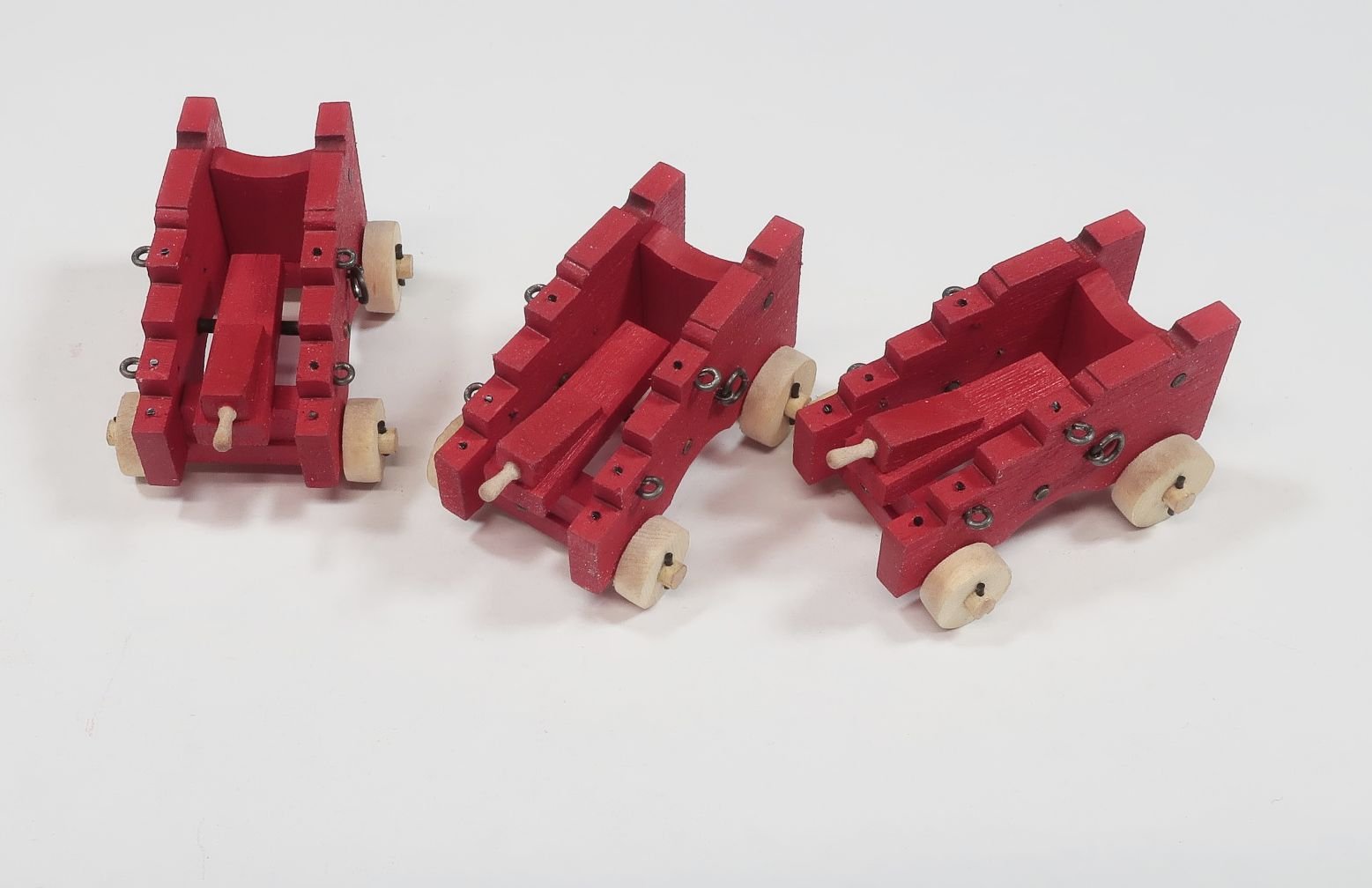
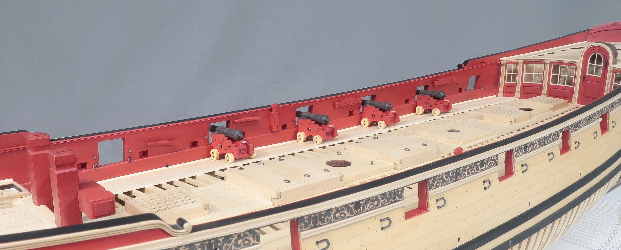
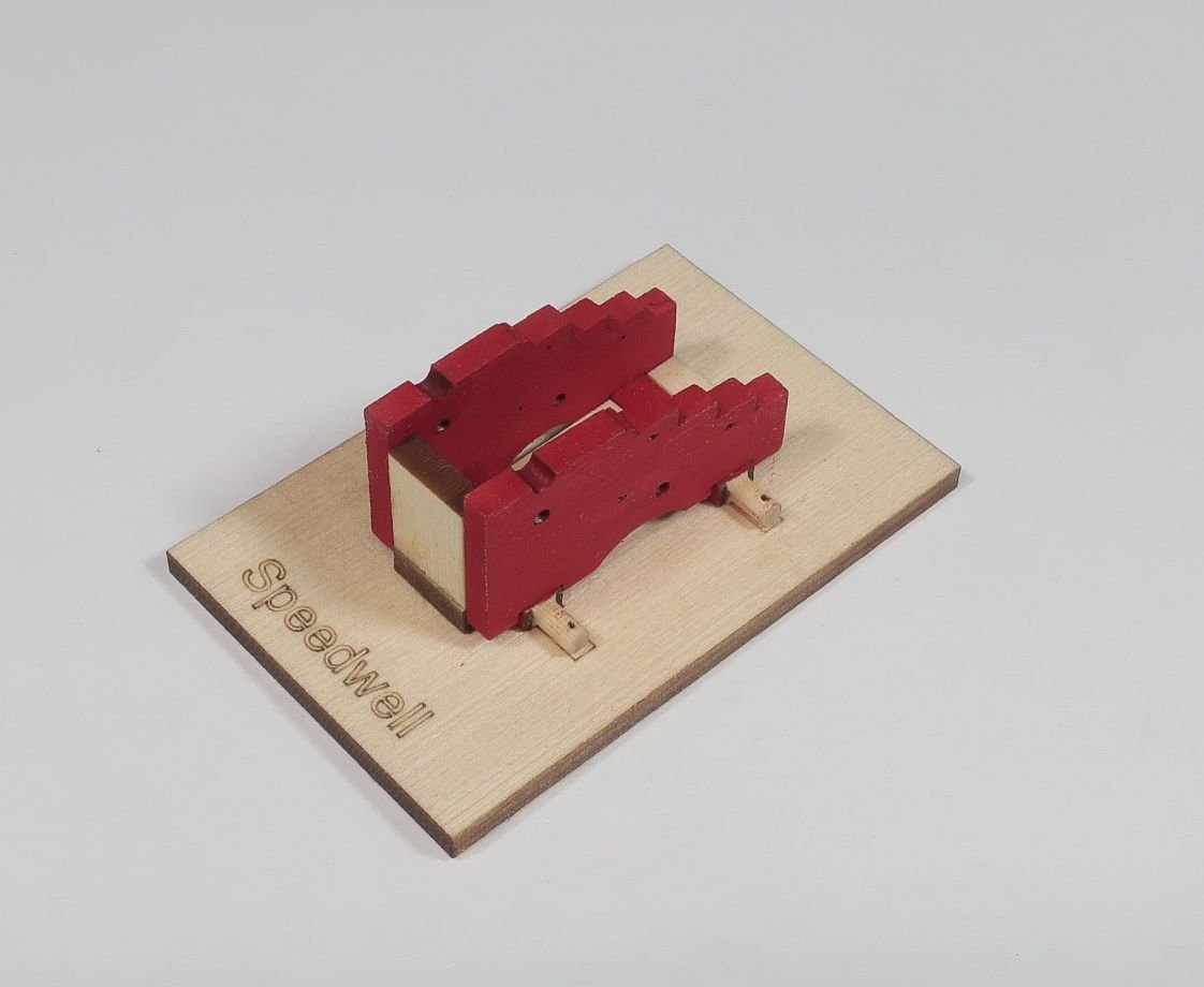
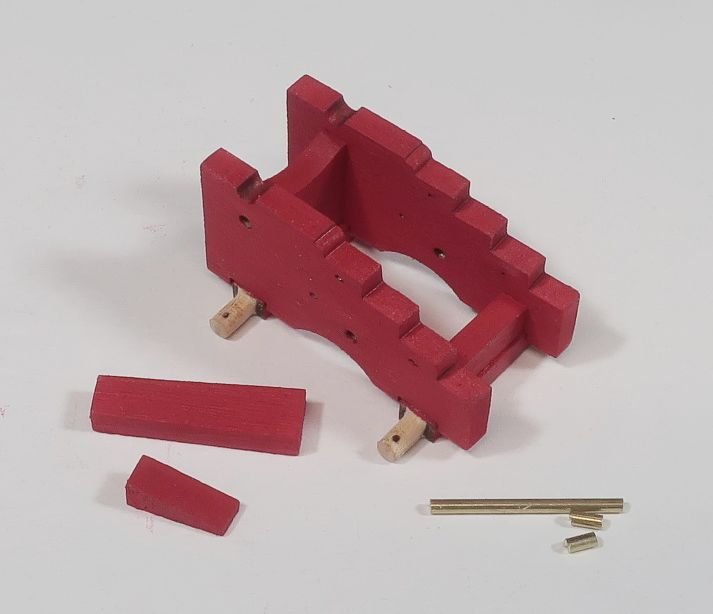
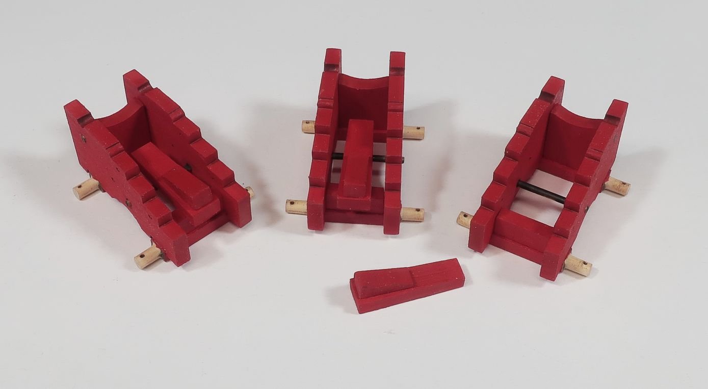
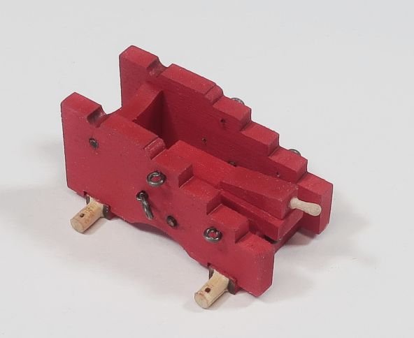
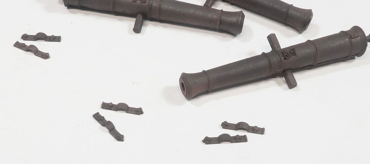
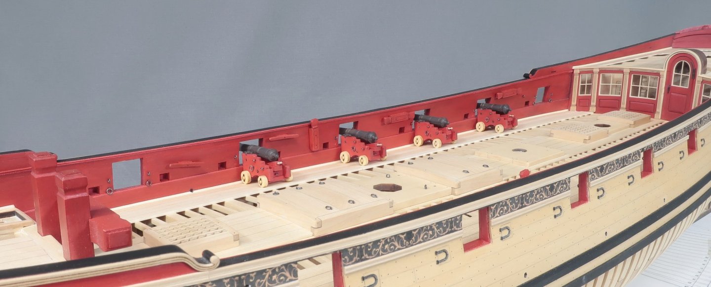
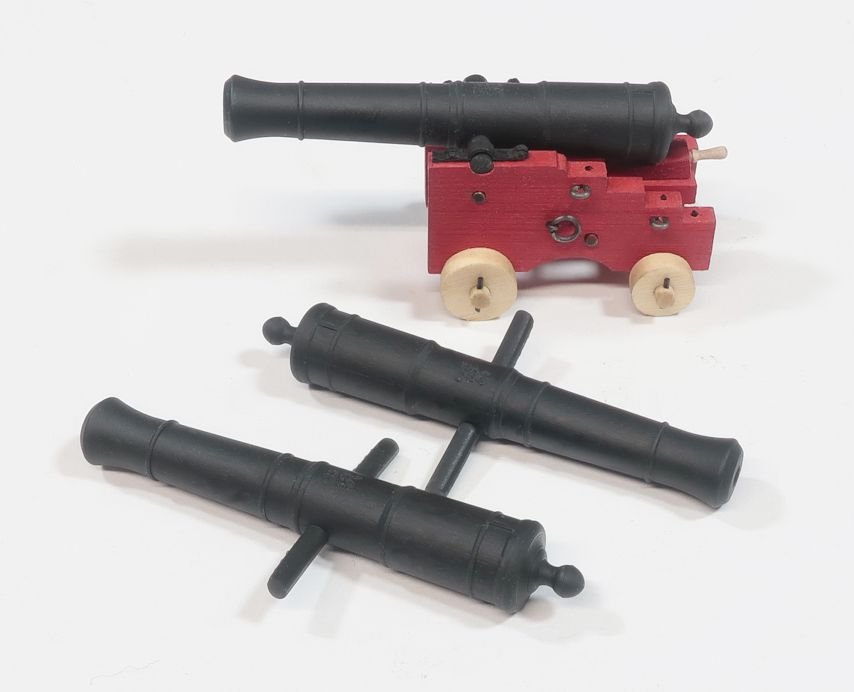
Making the guns.. There are 8 cannon. First sand the char off both sides of each laser cut sheet of carriage parts. Do this before removing the parts. Its just easier. Then proceed to remove the char from the edges of all pieces. Dont sand too much. Just a light touch is needed. The two sides or the "brackets" of teach carriage are laser cut with all the holes for your various eyebolts etc. Then if you intend to paint the carriages...do that on all parts before assembling. Its just easier. Note the axle are left bright as well as the wheels (trucks). In addition, this chapter will come with a carriage jig. It is a simple jig. Add the center piece of the jig first. Then it is best to add the two axles in position so you can better position the other two jig pieces. Position the two jig elements on the far sides of each axle so they can be easily slipped in and out of the jig. Dont make it so the axles are too tight in the jig and hard to remove. Finish up the the jig with the final fourth piece which is used to secure the brackets at the correct width apart from each other. Then you can glue the two brackets to the axles....after they dry remove this assembly from the jig and you can repeat for all eight carriages. Next up...add the front (transom) and the back (bolster) atop each axle between the brackets. Note the stool bed and quoin ready to go in the next step along with some 3/64" dia brass rod. Insert the longer brass rod (not included) through the carriage. The stool bed will sit on this. The two smaller lengths simulate the transom bolts. Normally this would go through the transom from one side to the other. But in our case they wont. They are just cosmetic. Just fill the hole so it looks like it does. They can be be blackened. Then I glued the quoin atop the stool bed in advance. Then glued this on top of the bolster and long brass rod. See the photo. Small eye bolts were made with 24 gauge black wire and inserted according to the plans. Many of you will be familiar with this repetitive task. I also made ring and bolt for the breech line. Even though the photos show it on the carriage, they will be removed for now. It is easier to add them to the breech line itself and then insert them into the carriage sides. That is if you intend to rig the guns which I do. I also turned the quoin handle from some scrap 3/64" boxwood strips. But you guys ,ay choose a commercial option of using a belaying pin...if they dont look too out of scale and huge. Which they almost certainly always look out of scale. To finish up the carriages I drilled the holes along the stepped sides of each bracket. I inserted 30 pound black fishing line to simulate the bolts. I also added the the trucks (wheels). To finish up the trucks a small length of either 24 gauge black wire or even 25 pound black fishing line can be used to simulate the truck keys. The keys are run through the laser cut holes in each axle. The cannon are resin...they are cleaned up and finished with some weathering powder as I usually do. The trunnion were sanded shorter to match the width of each carriage. The capsquares are interesting. I hate making these. So this time around I spent basically an entire day figuring out how to laser cut them. Thats right....laser cut. No 3d printing or casting. I designed and laser cut the capsquares in one piece. They do have some 3 dimensionality to them. I am quite pleased with how they turned out. It took many many failed attempts. Just clean them up and weather them if you like. Then glue them on.... The finished product... Questions or comments are always welcomed.


-
I am working on the cannon....will have a step by step very soon. The cannon will be fully rigged since I will be rigging the entire model. Four down and four to go!!
-
We shall see....It was only the first initial sets of chapters.
-
Nope ...not at all, LOL. That will all be removed and cut away anyway.
-
Perfect and such a lovely photo.
-
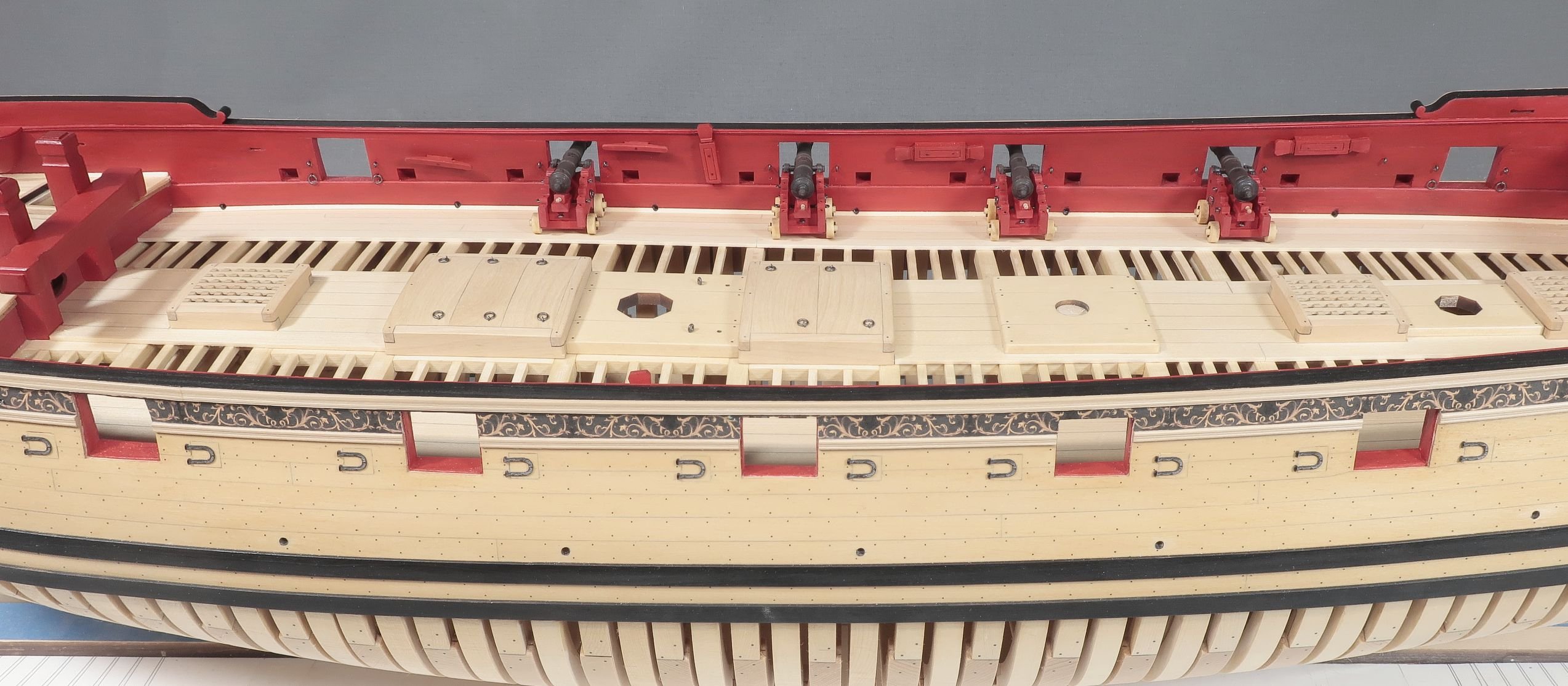
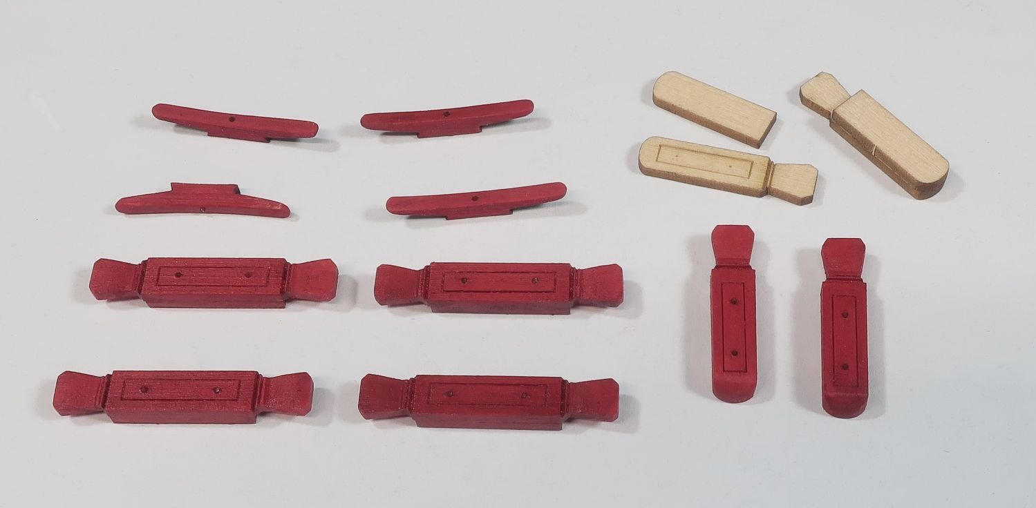
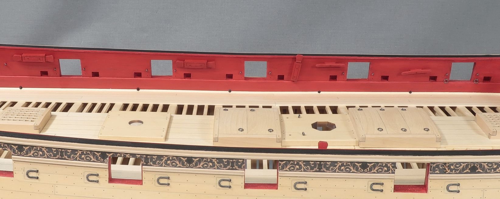
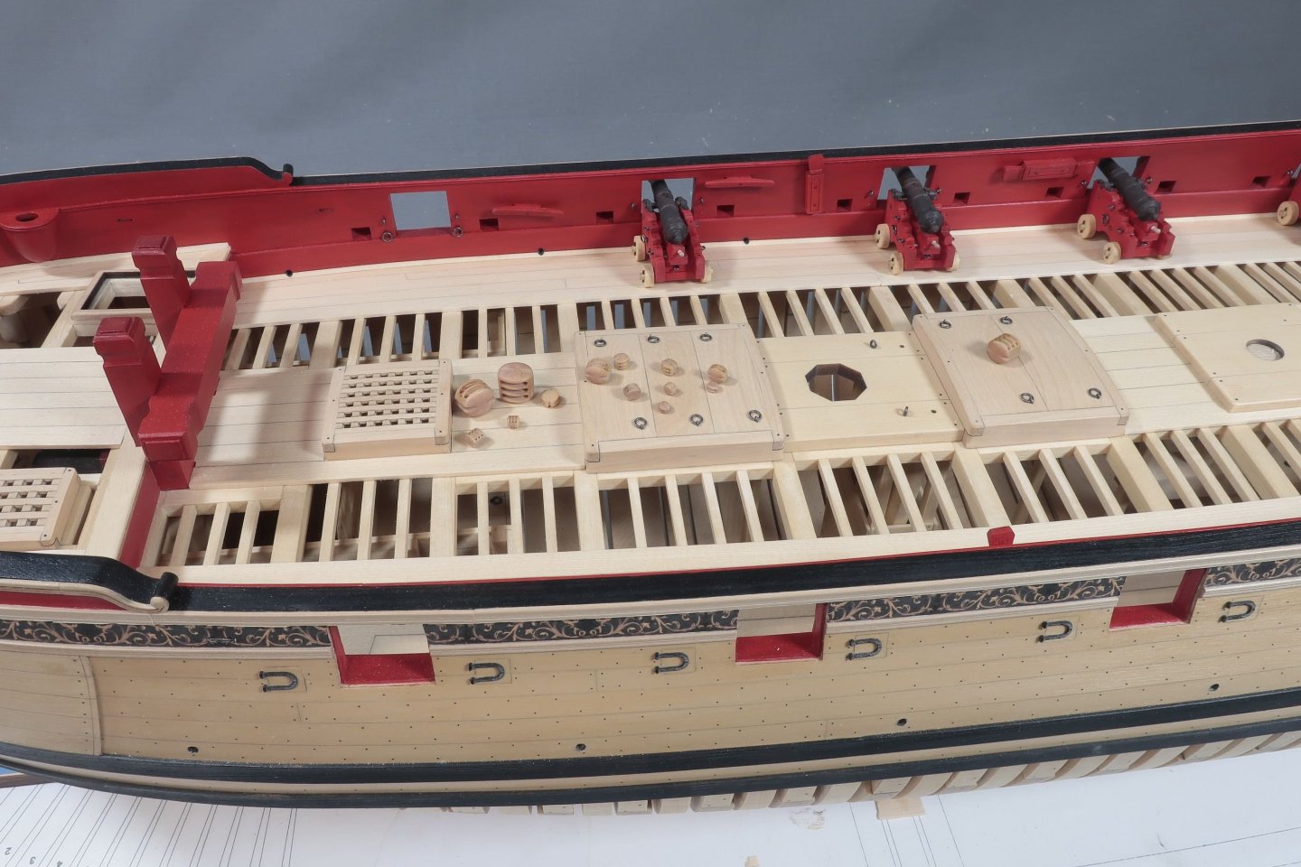
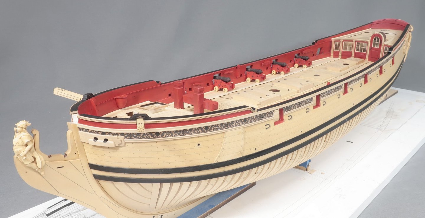
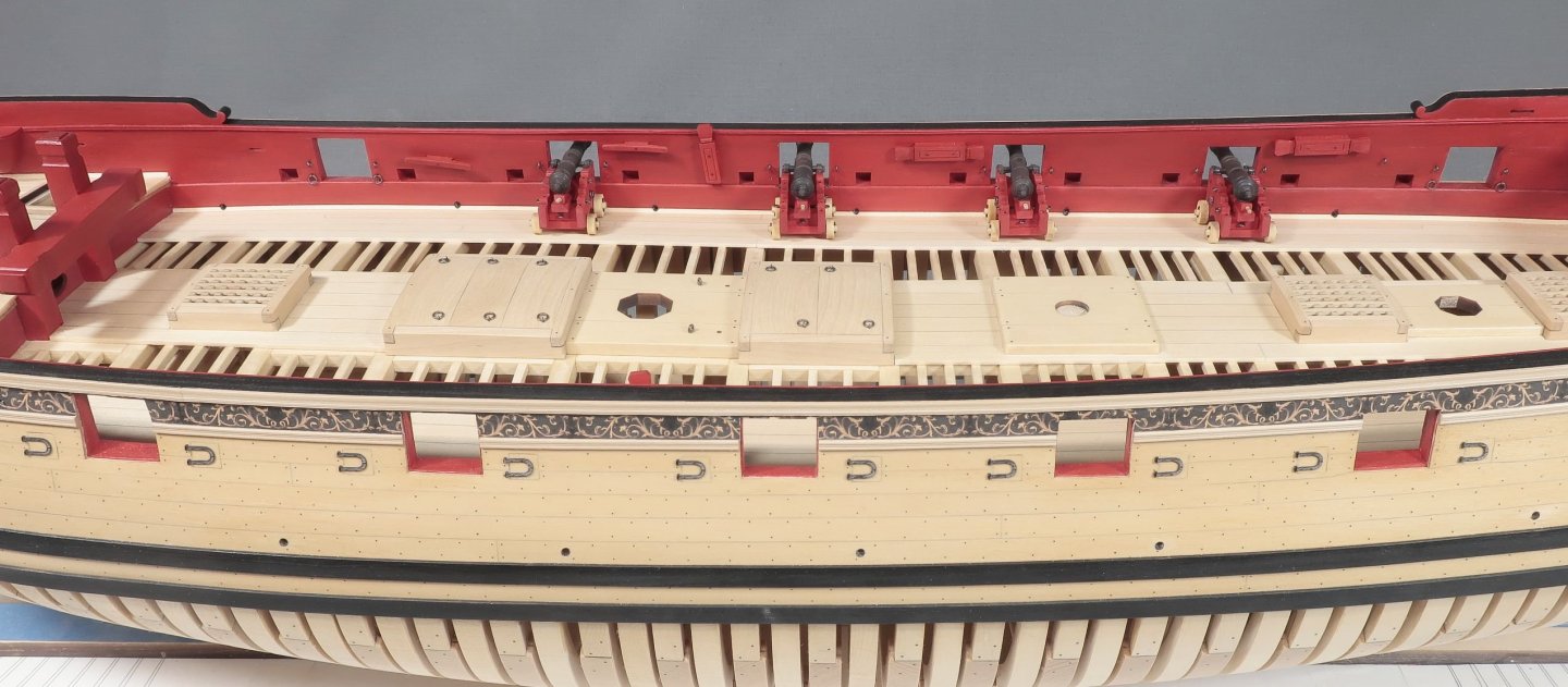
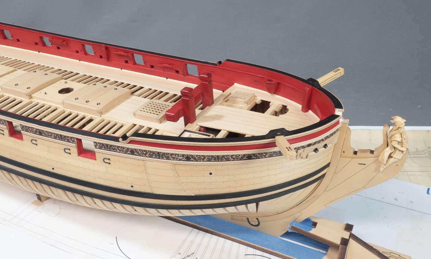
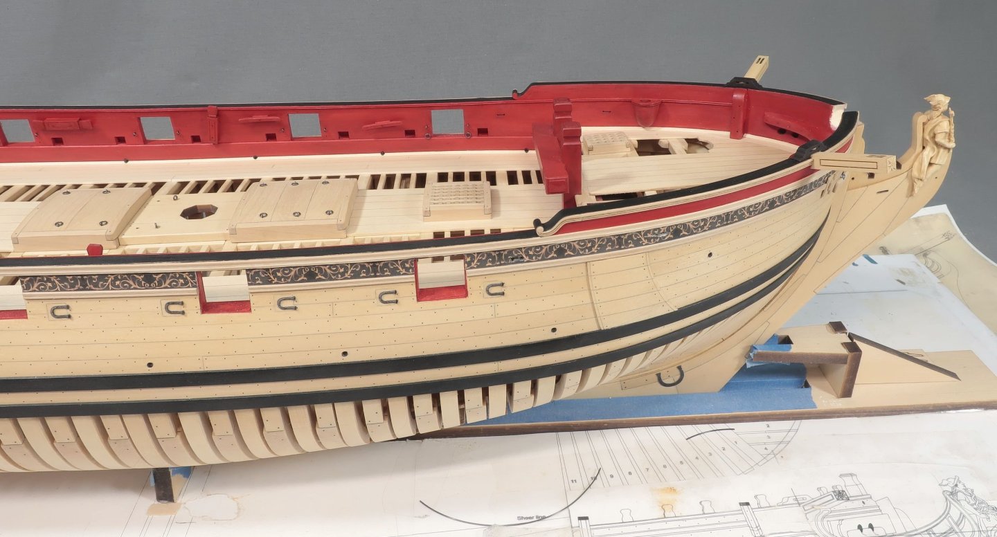
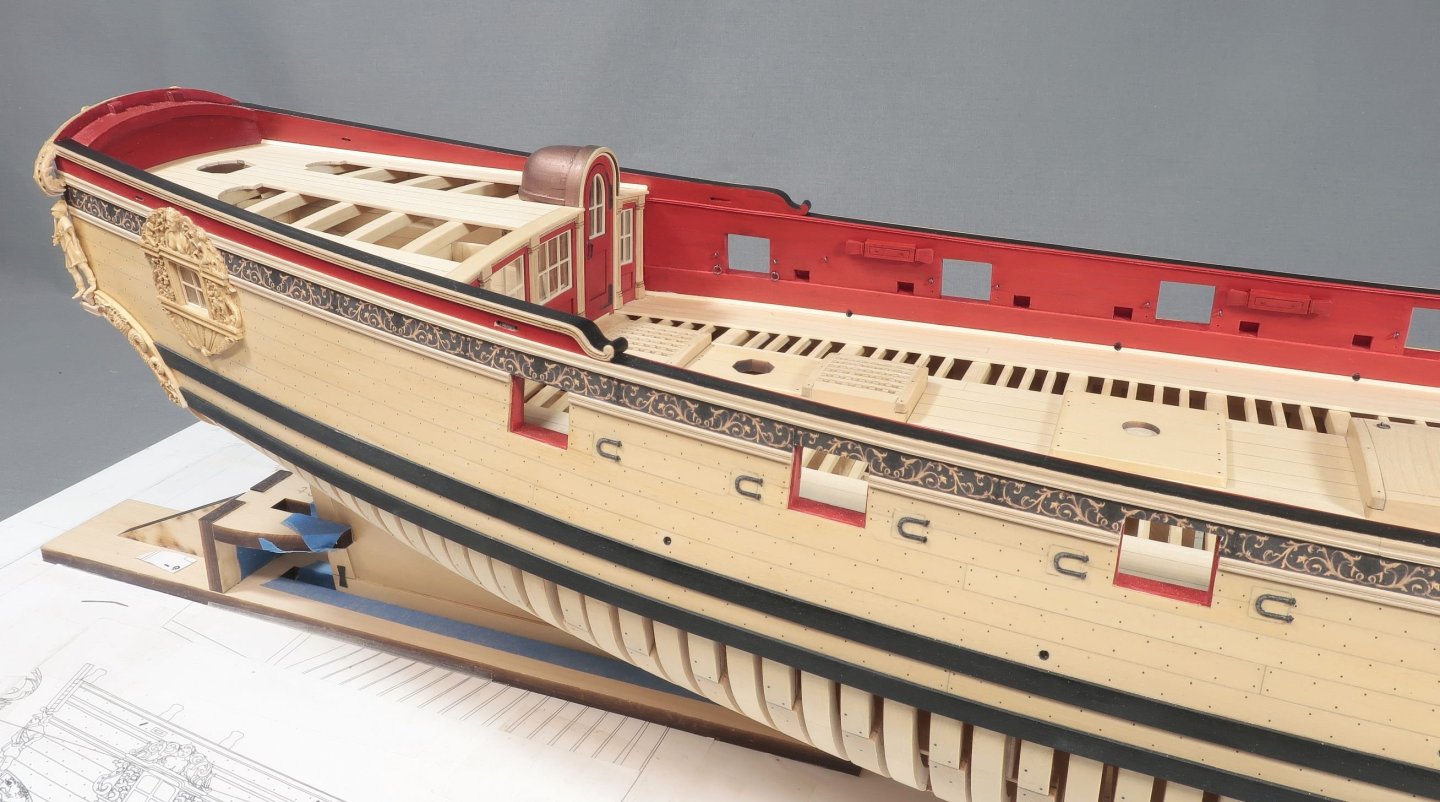
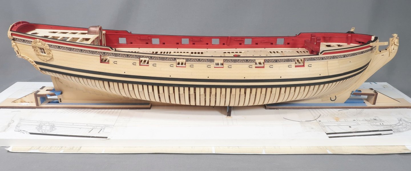
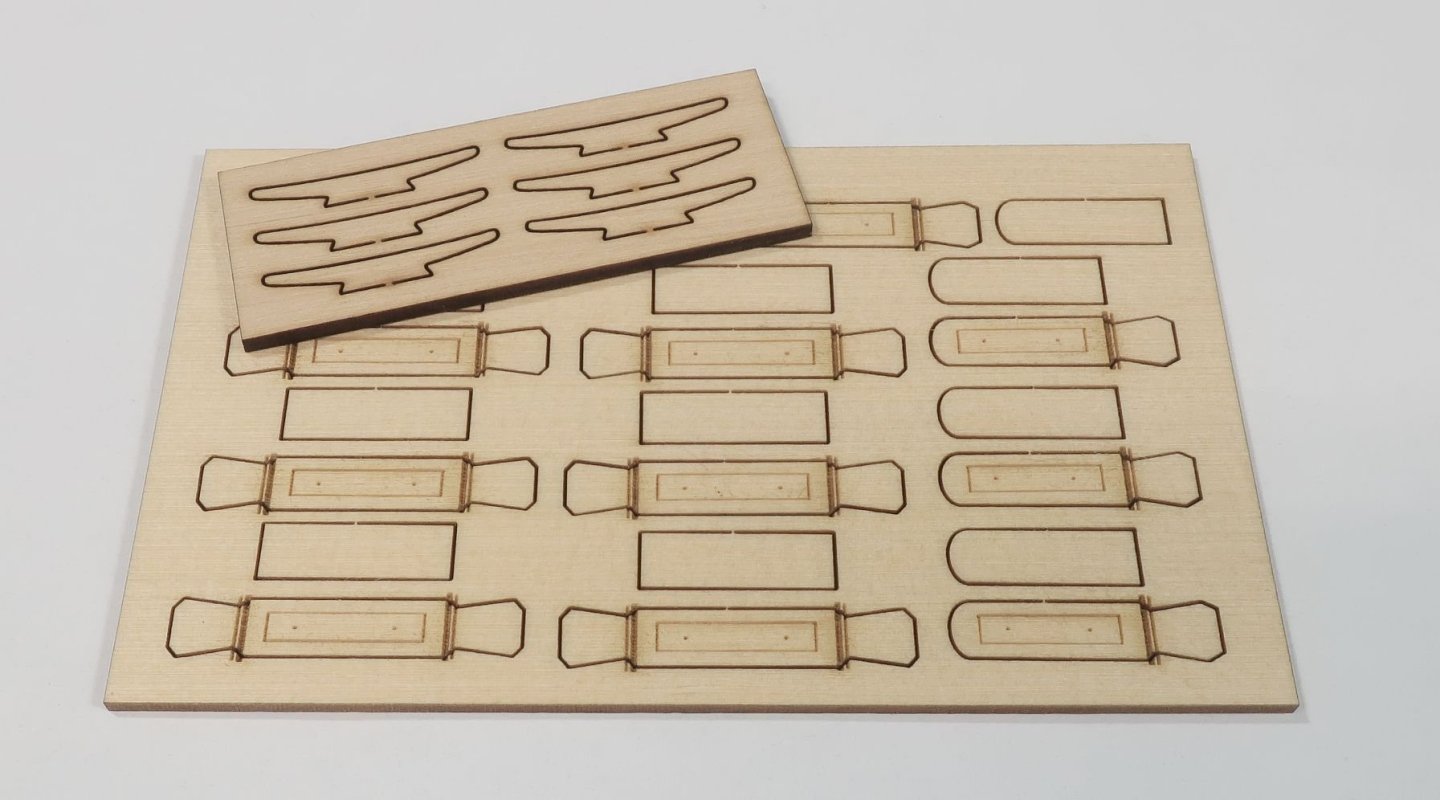
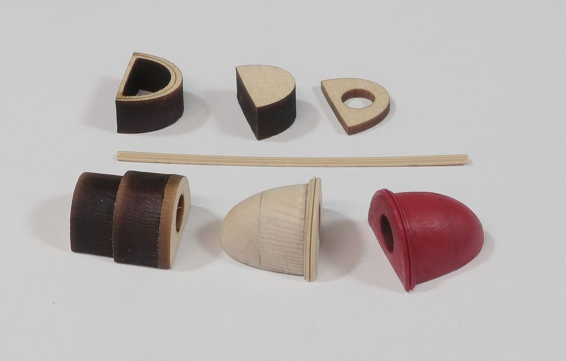
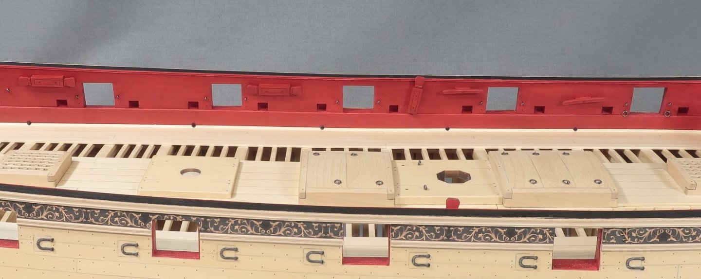
Bulwarks fittings...the seats, kevels and cleats etc The seats are made from three layers of laser cut parts. It sets up a sort of "lift" scenario so you can eventually sand the seats to the required shape. The shape is shown on the plans but the parts kind of dictate the shape which is good. I used sanding sticks of various coarseness. Starting with a 200 grit and working my way to a 320 grit. Then the plastic molding was glued along the top which matches the same molding we just put on the inboard bulwarks. It was all painted red. The various stages and parts are shown below. The kevels and cleats are rather simple to make. They are all laser cut as well. There are two types of kevels. They are made the same way. Glue the back piece on the kevel which lifts the timberhead away from the bulwarks. The char was sanded off and then the timberheads were shaped. They were shaped on and angle so they have some dimension so they wouldnt appear to be so flat. I hope that makes sense/ I used small files to do that. Note the ver delicate and thin laser etched carving details. I have spent a great deal of time looking at many contemporary models and the details on these small fittings. Any carved grooves and details are usually very shallow and thin. Most kit makers go overboard on making these etched details too wide and too deep. It just looks too kit-like. They dont look anything like how the original model builders back then carved these details with such skill. I am making a every effort not to "over-use" the capabilities that our current technologies allow so I can preserve a pretty good resemblance to the old hand-made stuff. I have been guilty of not doing so and falling into the same trap that other mfg's fall into but I am trying my best this time around. Note how shallow and thin the carved details are on these kevels. That is all you really need. "SUBTLE" was the word of the day for me while drafting those. The kevels were painted red and the bolts simulated with 30 lb. black fishing line. The cleats are self-explanatory. The char cleaned off and the ends were rounded of a bit. They were painted red also and some fishing line used to simulate the center bolt. Then they were glued onto the model. In addition I added the eyebolts needed for the gun tackles. These were made from 24 gauge black wire in the typical way we do that. You might notice only two of the ports have the eyebolts and split rings for the breech line of the guns. That is because there are 4 guns on each side and it is easier to add them to the breach lines first. So I just drilled the holes for them in the bulwarks for now. Then I can simply slip the breech lines into position after making the guns and carriages. NOTE...there is one additional stray eye bolt aft for some rigging. It is just behind the aft-most kevel. Dont forget to add that one. It is shown on sheet three of the plans. The seats were glued in position keeping them in line with that molding along the inner bulwarks. I located where they would go and then removed a small section of that molding where the seats would be fitted. I think they turned out quite well. I did in the end create the discharge hole for the seats. I took a cautious approach making them the same way as the scuppers. In fact the discharge for the seats were made the exact same size. Right or wrong I do not know...but thats what I ended up doing. Here are more photos of the kevels and bulwark fittings. You can just see a whisper of those carved details on the kevels which is un obtrusive and not in your face. This is actually just like how they look on the contemporary model of Speedwell. Next up will be the eight gun carriages and guns...and rigging them on the model with gun tackles. That will finish up chapter 8.

-
You could give it a few swipes. But you will be fairing inboard at some point and that will all be removed later. But its best to get rid of most of it now as it will dirty up your hull.
-
I dont quite understand the question. Perhaps a photo?