


Chuck
-
Posts
9,725 -
Joined
-
Last visited
Content Type
Profiles
Forums
Gallery
Events
Everything posted by Chuck
-
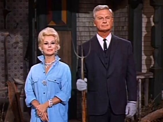
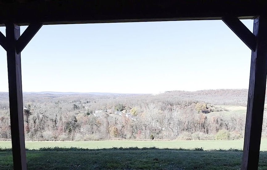
 Its going to be a very big adjustment....My current view just six miles out of NYC. From my upstairs bedroom. Its a very different vibe. I am gonna feel like Oliver and Eva gabor, LOL
-
USPS is now shipping to Canada again. So I have enabled Canada in my online store and have started accepting orders again. I have no idea how long it will take to get there but at least you can place orders again if you live in Canada. Chuck Also.....FYI....The last day for any orders before my move is January 17th. I will be closing the entire store down in order to pack up my shop for the move. We are physically moving the first week of February 10th and it might take a week after that to set up the shop again. So I expect to reopen the store as soon as I can after Feb. 10th. Thank you for your patience!!! I am so excited about enjoying the new view from my workshop.
-
HMS Winchelsea (1764) 32 gun frigate GROUP PROJECT INFO
Chuck replied to Chuck's topic in Group Projects on Model Ship World
Absolutely -
Looking ship shape Rusty. Very nice.
-
Really nice…love how the Cherry version turned out. Just an amazing job on the model.
-
Beautiful model. Bitter sweet I imagine as I always feel that way after finishing a long project. You made a fantastic Winnie. Chuck
- 399 replies
-
- 4
-

-
- winchelsea
- Syren Ship Model Company
- (and 1 more)
-
I will consider that....I have a lot more unusual blocks to make first....shoe blocks and rack blocks and euphroe blocks for example. Also some cleats and other misc stuff. Chuck
-
Those new deadeyes look very good on the model. Well done. I am shipping your 4mm deadeyes out this morning!!! I cant remember if you you bought any of my resin blocks in the past but if you want to sample them also let me know. No 3d print layer lines and they are very smooth. Even down to the 2mm sizes. I am actually making a bunch more of them today....sister blocks and clue blocks.... as they are selling out quicker than I thought. Chuck
-
Quite nice indeed. Well done. Chuck
-
So sad and we have all been there. She was a sweetie. My sympathies. chuck
-
Really nice work. Well thought out and executed.
-
I really wish I knew. Probably not a permanent thing is my guess.
-
Yes it is that tall. Maybe they had a tall topgallant mast but look how short the topmast is. Its a weird rig and I didnt really use it. I mainly used the rig from the contemporary Surly model and the early cutter in the Science museum. But that is an earlier cutter but close enough for my tastes. Chuck
-
That model is actually mis identified. It is not actually the Cheerful or Surly. In fact, for most of its time is was just named as an unidentified cutter. It is most likely a much later cutter based on certain things. But there are too amny crazy differences between the original drafts and that model. I am talking about many many. Position of hawse holes, wales , channels , gun ports etc. in addition, the model was rigged and re rigged many times over the years. It is not original. Check out the position of the topmast on the wrong side of the main masts. So take that model rig with a huge grain of salt. I was told by the curators that the rig could be a construct from two different contemporary models which is what Henry Culver did quite a bit back in the day. Use the Surly model in the Canada collection instead.
-
That is really taking shape Rusty. Looking great.
-
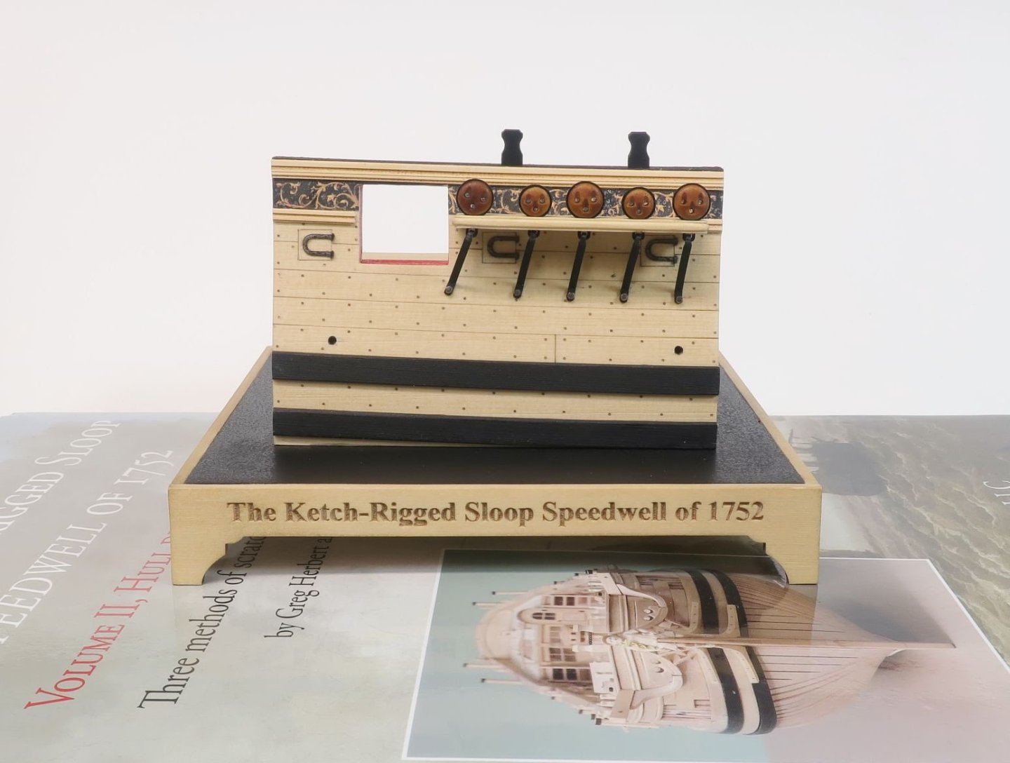
Its 3/8” scale just like the full hull model. Thanks guys for kind words. This project is essentially for my club and I will be making a limited run of about 25 kits. All of them will be given away. A dozen of them will be given away as door prizes at this years Joint Club's show in New London Ct. It will be part of the raffle at the April show. A dozen of them will be raffled along with a Preac Saw. Some of you might recall that I did a similar thing many years ago with a limited edition boxwood kit of a pinnace at a joint clubs show. This is essentially the same thing. Six more of remaining will be auctioned off here at Model Ship World. Chuck
-
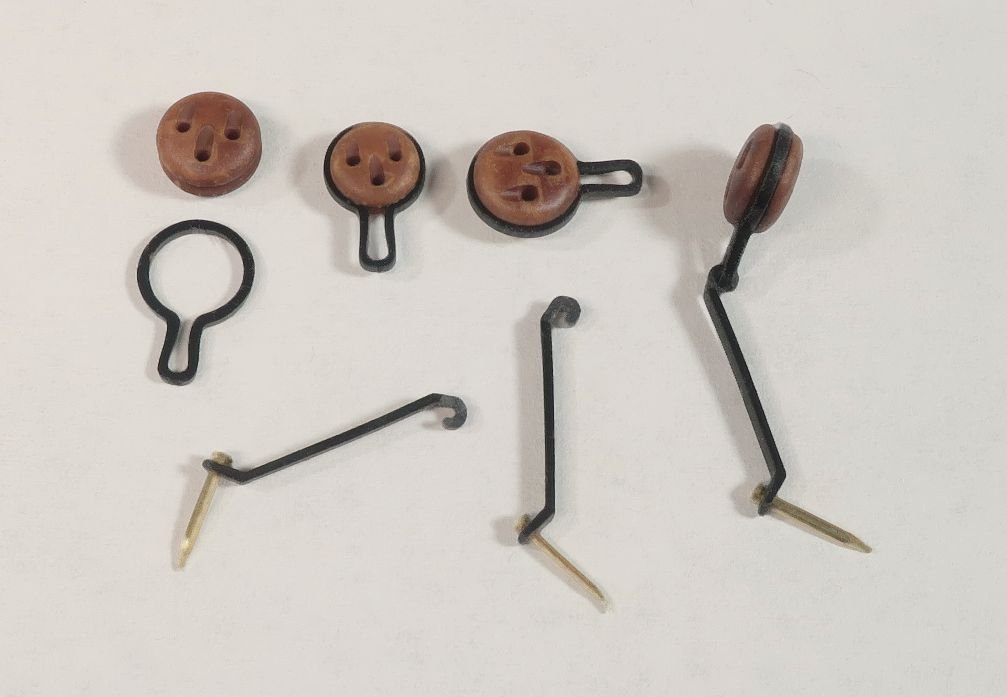
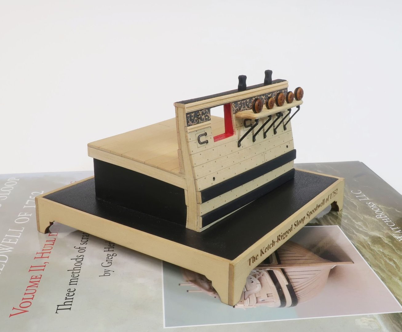
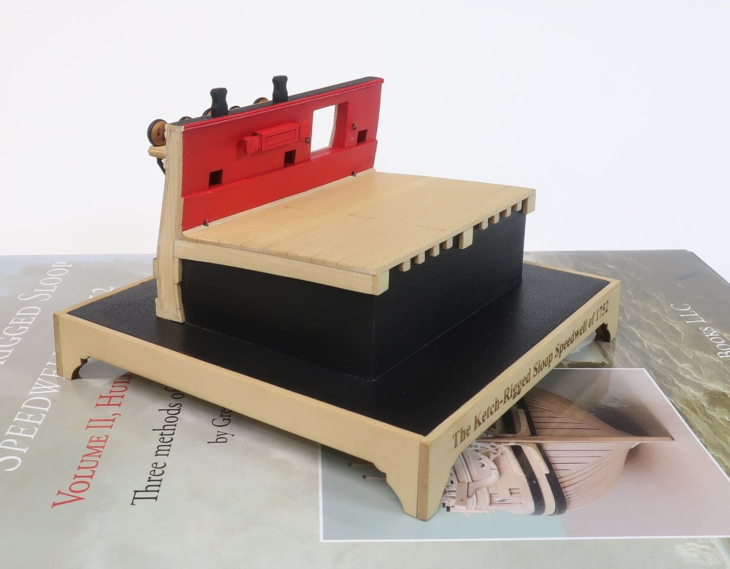
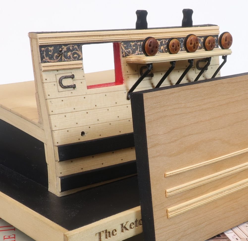
Although time has been limited for me for working on the model, I have been making progress. I have finalized the way I will do the deadeye strops and chainplates. These are all laser cut and makes life a lot easier. Once designed the actual construction time was non-existent. It took seconds to add the strops. This was just a test run but an improved version of those I developed for the Winnie. They really do just slip right on. There will be two sizes of deadeyes and strops. The chainplates will all be the same more or less. They are laser cut and 1/16" wide and about the thickness of was brass straps would have been. You must do a little bit of work on the straps but not much. The hole for the little brass pin must be drilled through the bottom of the strap. I used a "67 drill bit. Its acrylic so this was so much easier than drilling through brass. At the top of the strap there is a little "hook" shaped on the end. This will fit into the bottom of the strop after the deadeye is placed on the channel. The width is 1/16" as I mentioned which is a tad wide for the hook to fit in the strop bottom. So this was filed narrower on both sides. This was done just at the "hooked" part of the strap which fits into the strop which you can see above. They are cut from black acrylic so no need to blacken but you may want to weather them a bit to "metalize" them in appearance. This is what they will ultimately look like on this sectional model which was really fun to make of the Speedwell. The deadeyes are my new resin 3D printed ones. These are the color of Swiss Pear. I will be using these on my model. You can see how nicely the straps and strops worked out. Also have a look at those molding strips on this sectional model. The fancy molding. This was a new test and also laser cut. I will be using them on the sectional model projects. The inboard side. The entire sectional test is completed. I just have to add and rig one cannon. That was the whole purpose of this mini-model. It is to be used to help teach building techniques for cannon carriages and the their rigging. My local club members in NJ will be using it as a quick and hopefully fun group build as a tech session taught by me. It should be fun. There will also be some gun crew figures added. This is a close up of the molding test. I know how some guys hate creating scrapers to make their own molding. This will save the guys a lot of time. I am thinking about offering these as stand along optional moldings for the big project as well. Or for any model really. There are three profiles. 1/16", 3/32" and 1/8" wide. All three are 1/32" thick. They are laser cut on Syrenite. They can be used as is but I do recommend sanding the top and bottom edges to soften them and round them off. Although the color as is looks great. I like to enhance it by wiping some Gel Stain on them and then wiping it off. It settles into the grooves and help highlight the profile. It deepened the color a bit as well. You know...just like I handle making the carved resin figurehead and stern figures look like boxwood. It takes about 2 minutes to do. Then wipe off the excess. The more coats the deeper the color depending on your preference. I think folks might like the option to buy these molding strips regardless of the project. So expect soon. But let me know if you are interested as I wont waste material and time if there is little interest. Volutes and scrolls should be easy to add to this line of products as well although every model uses a different size scroll-work. So maybe I have to thing about that. It can also be painted and as I said sanded easily.
-
They look great Mike.
-
That looks very good. Its finicky for sure but the results speak for themselves.
- 399 replies
-
- 2
-
-
- winchelsea
- Syren Ship Model Company
- (and 1 more)
-
Nicely done. The belfry looks fantastic. You managed to get it super clean. The extra care paid off immensely.
-
Not easier but its really up to you. Whatever works for you. Those tend to be way out of scale and look clunky when rigged. So I prefer less fussing which looks smaller and more to scale. I feel this method also helps the rope lay more naturally.
-
It looks really good. Just keep those small pieces for when you remove all of tour jigs. You will see where they go later. But seriously they are not important at all and will eventually be completely covered up. Chuck
-
FYI… As of today the US Postal service will not ship to Canada during the strike of Canadian postal workers.. I have a few orders to ship and will simply hold them until after the strike. But if you wish to cancel the order please contact me. In the meantime, I will stop accepting orders to Canada until after the strike. Sorry but this is completely out of my hands. Fed Ex and UPS will soon follow suit.
-
Chapter 3 is now available. I made 12 sets for now and half are already gone. So please only buy it if you are close to needing chapter 3. There are several folks who are really in need of it. I know that many who have ordered this chapter havent even started chapter one yet. Please dont buy it yet. I will make more very soon. It is not fair to the folks who are up to this point of construction. Thank You. I may have to cancel an order so that those folks who are truly up to this stage get first crack at them. Chuck


