michael mott
-
Posts
5,200 -
Joined
-
Last visited
Content Type
Profiles
Forums
Gallery
Events
Everything posted by michael mott
-
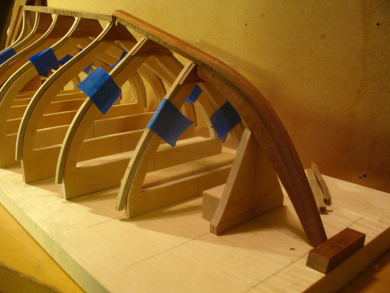
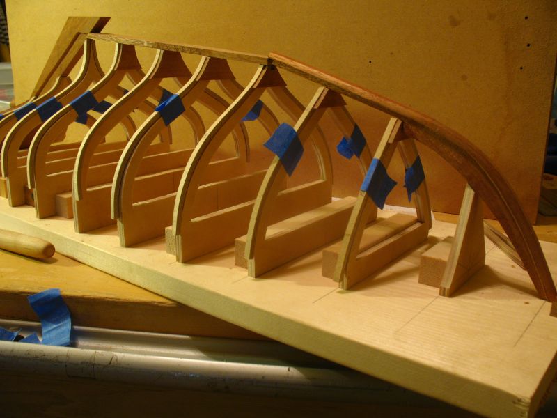
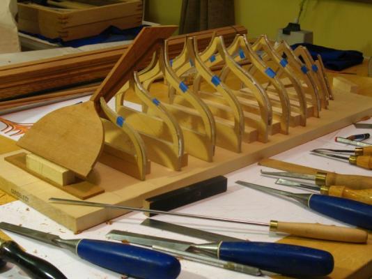
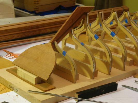
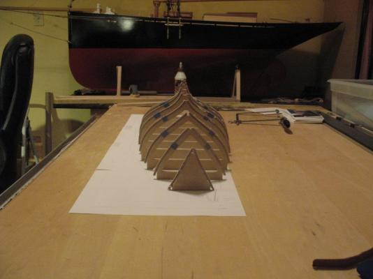
 build part 9 Finally getting things sorted. When one makes an error it often seems to have domino effects, I have been working to pick them up again. just a couple more to go. Michael
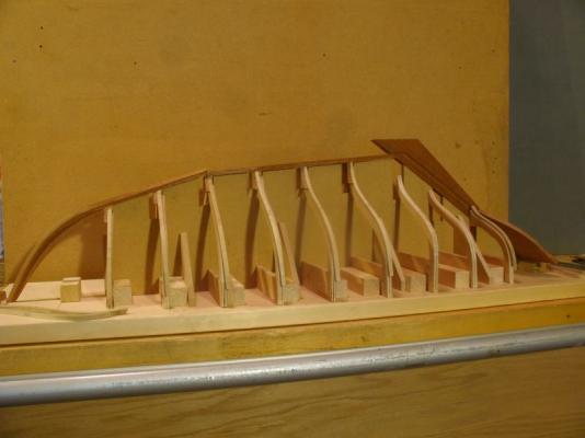

-
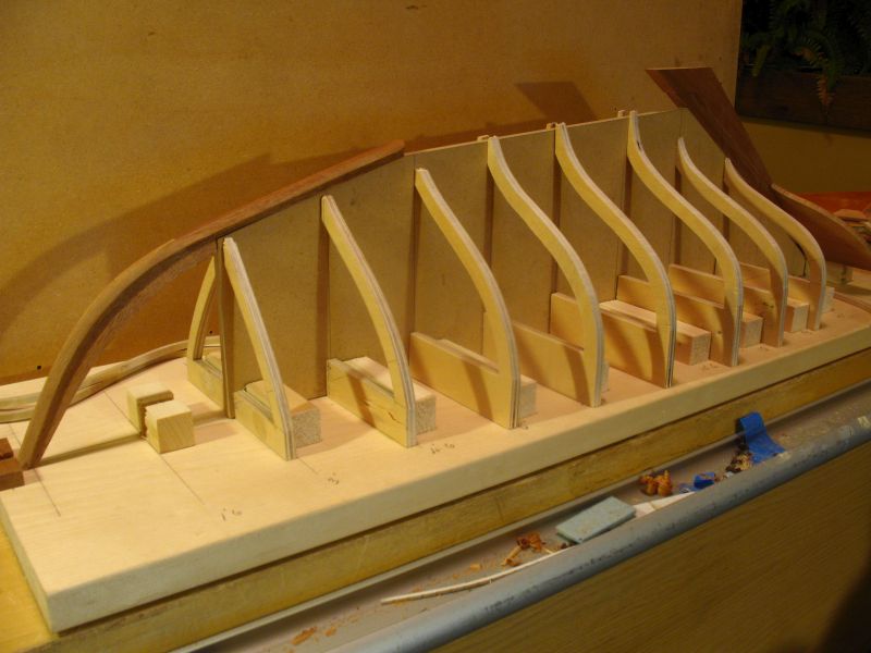
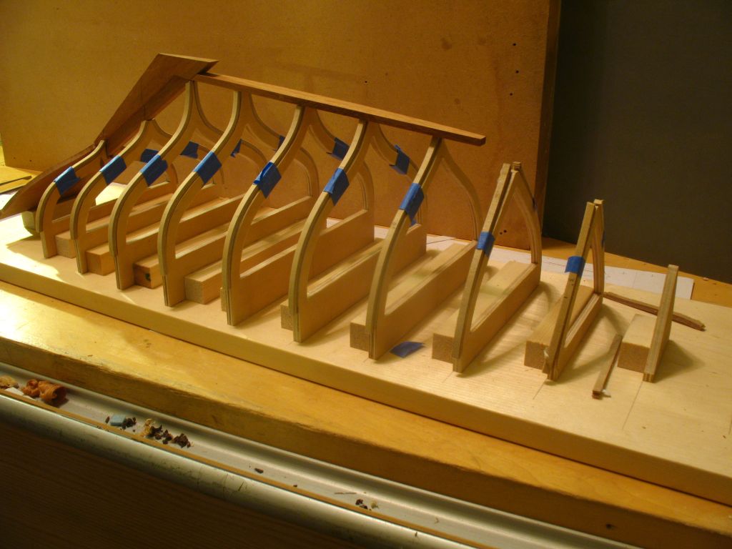
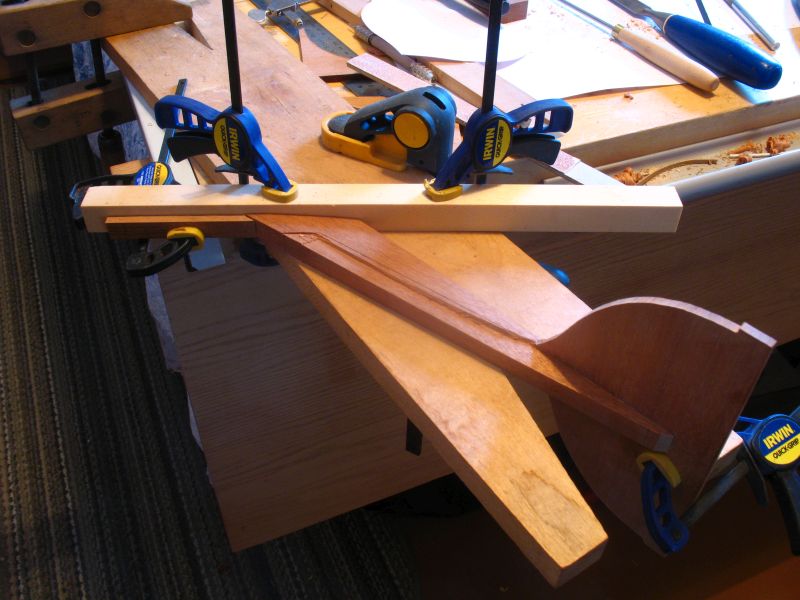
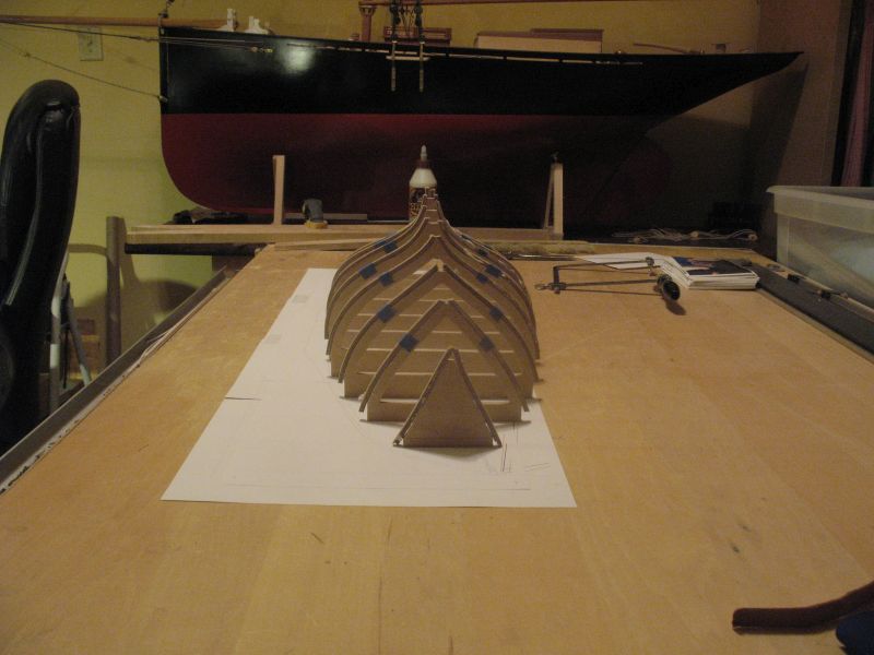
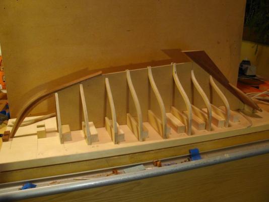
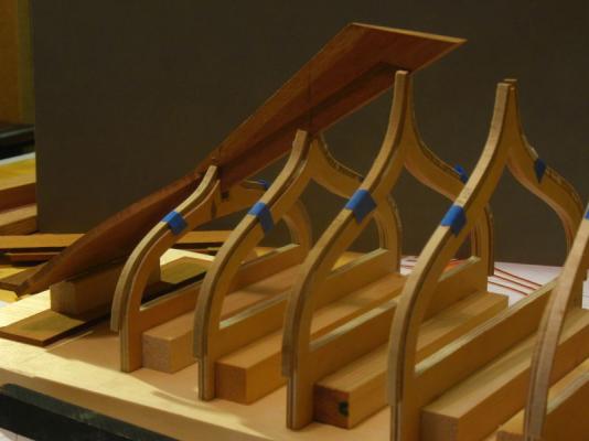
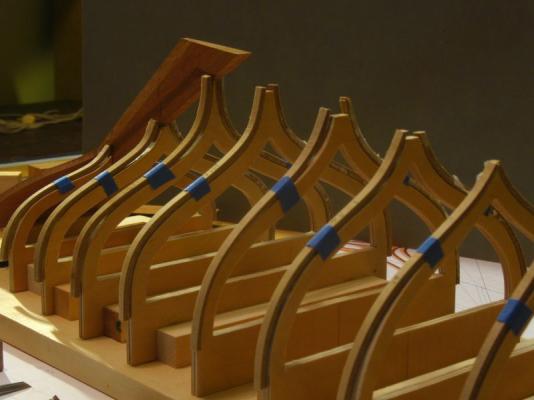
Bob Patrick and Mark, thanks for the kind remarks, and thank you too All who visited and pushed the like button. build part 8 Well things have a habit of creating little issues that need to be sorted. first I began shaping the stem and forward section of the keel Then after placing it on the molds something just did not seem quite right. A lot of measuring and revisiting the drawings there was some errors in the alignment of the keel parts. to solve this I needed to rework the way I am putting things together and so I cut a sheet of 1/4 inch MDF to act as a central support for the keel this way it will be exactly as the lines profile. It meant cutting the stations in half and removing the 1/4 inch from the middles but I was also then able to check that both halves matched properly as well. A bit more fettling before I get to the planks. I need to cut some notches for the frames and the glued plates to slip back in. Michael


-
To quote a line from an old Movie "That's not a knife this is a knife" Merchen thanks for the picture i can see how the way you are holding it that it works more like an engraving knife. Michael
-
She is looking great Vaddoc, nice work on all the rigging fittings, i like the chocks, what type of wood did you use? Michael
- 253 replies
-
- 2
-

-
- ketkch
- gaff-rigged
- (and 1 more)
-
Patrick She looks like you have got the superstructure pretty much solved. coming together nicely. Michael
-
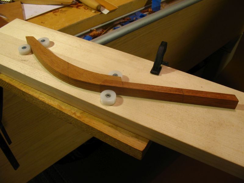
Build part 7 A bit more work on the keel plate. I will need to add the supporting plates before I fix the keel to the frames. Michael

-
build part 6 A little more work shaping the stern post, I have a whole new appreciation for those members who cut and shape the hawse timbers and the rebates in the stern and deadwood of the larger ships of the line. This is a lot more difficult than it looks on all the other build logs I have looked at. These first fittings are an eye opener to the complexities of the shape of the keel and stern on these little boats. Michael

-
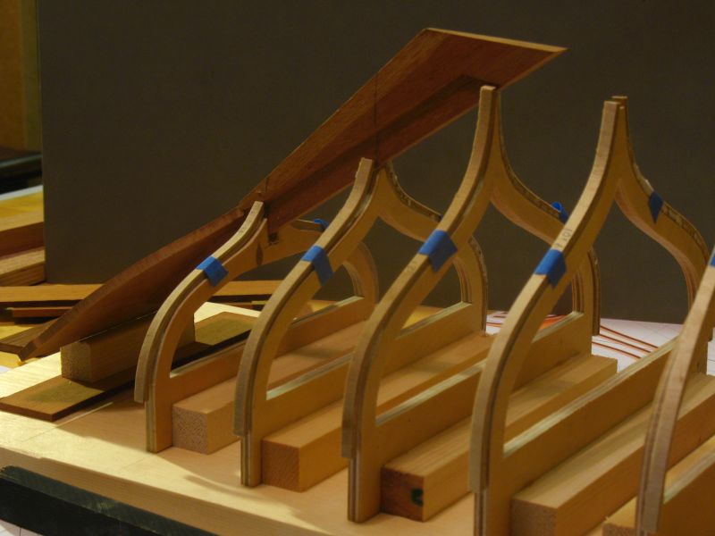
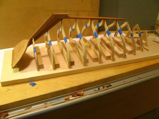
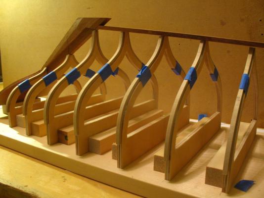
Hi Bob thanks, Nils yes the blue tape is very temporary the frames still need to be finally sanded and cut to their finished lengths. Also the keel needs to be fitted before any planking goes on. Thanks to all who pressed the like button. Michael
-
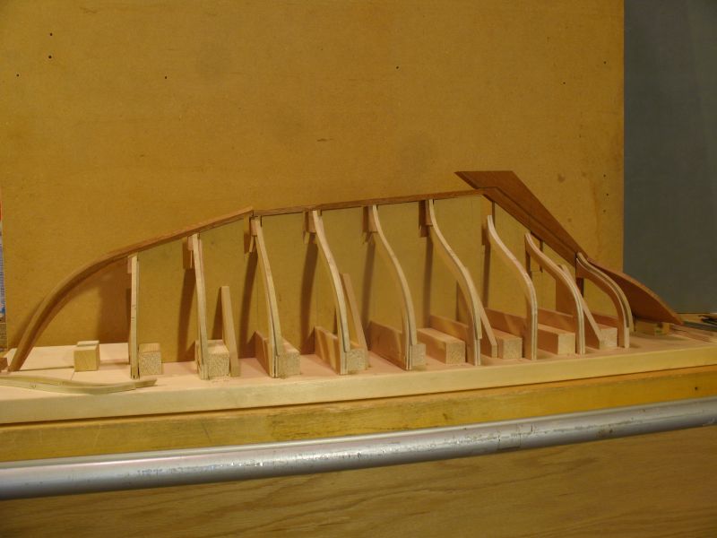
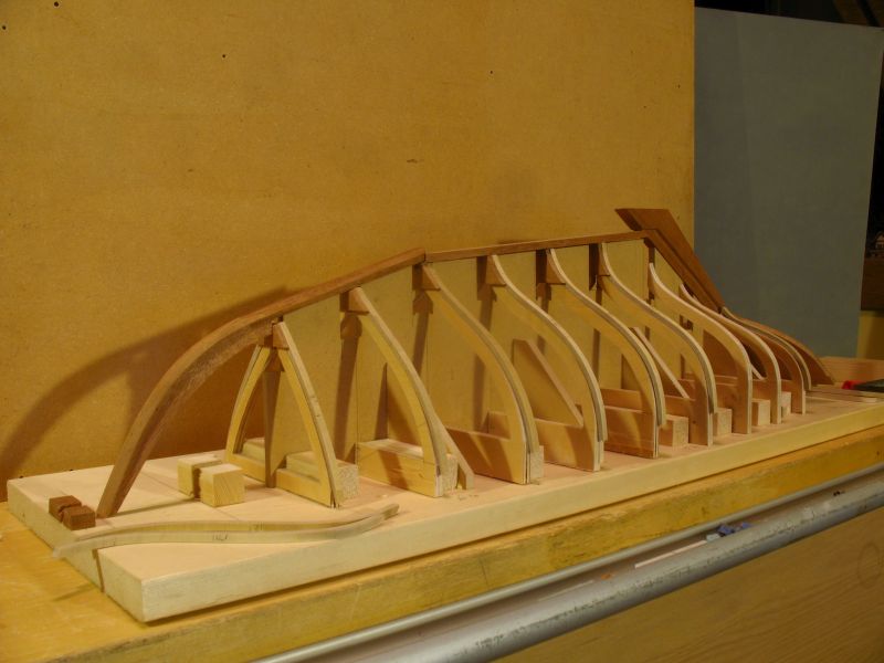
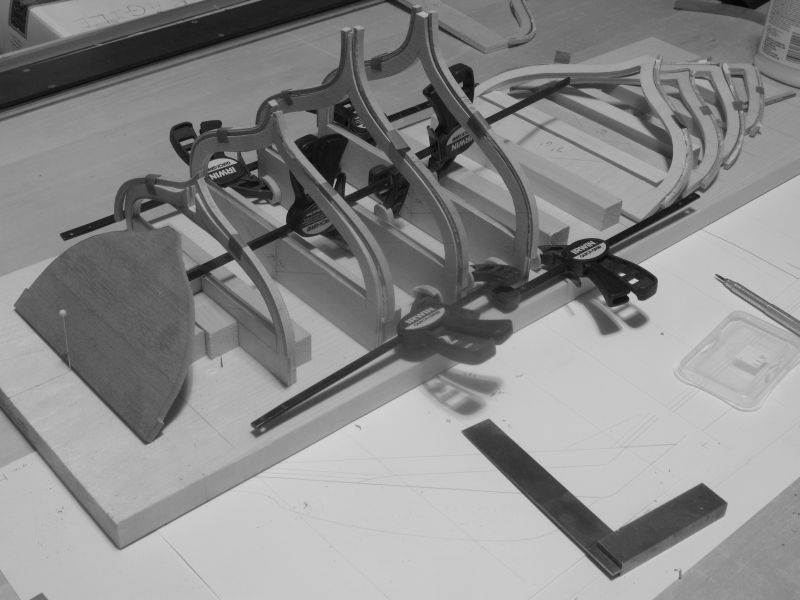
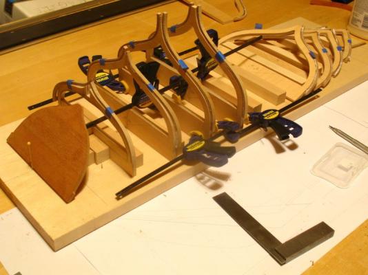
Thanks for the nice comments Pete and Patrick, Build part 5 The building bard is a piece of 1x10 clear pine, I wanted to keep this simple The support pieces are 3/4 x 3/4 and just glued with a couple of small spots of glue to hold them in place without a lot of fuss. I did position them so that the stations aft of midships are set to the aft side of the line and the forward ones forward of the line. this will help when fairing the frames. The transom is glued from three pieces of 3/16 x 1 5/16 mahogany I glued them the same way that I would a board for a cabinet. I planed the edge with a hand plane then rubbed the joints together with the glue and propped it up to dry. this method does not impart any stresses into the glued material. The plywood molds were not perfectly flat and are glued to the support blocks with a couple of spots and clamped. I will attach the transom to the stern-post once it is cut and shaped. Michael


-
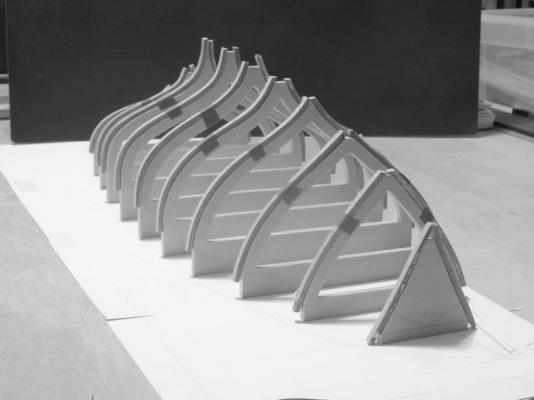
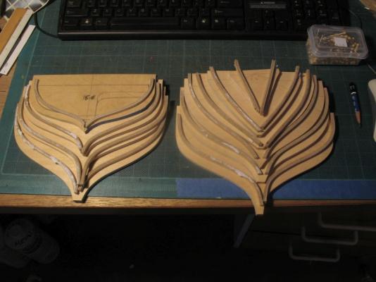
Thanks Bob and All the members who added likes build part 4 I finished fretting out the molds this morning. I now have to sand the frames and fix the molds to a building board and add the transom, it will be mahogany. Michael
-
Matti, first Merry Christmas and welcome. Very nice work on the Clara May. Birch is a wonderful and very versatile wood for building with, it is obvious from the speed and skill with the materials that you will enjoy many hours with the ships and boats. Michael
-
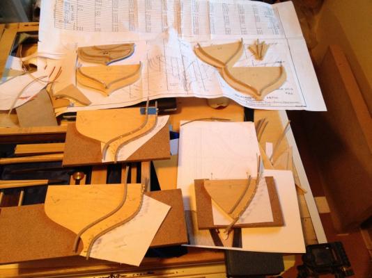
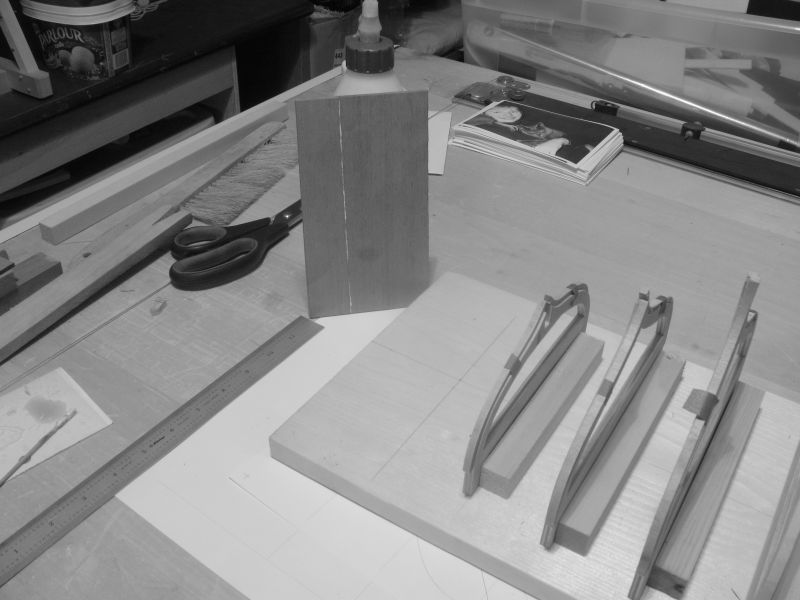
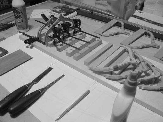
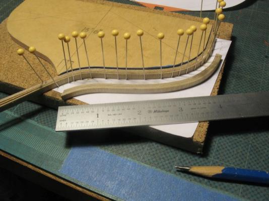
Build part 3 I completed the first major task this morning all the frames are now laminated for the molds. the other frames will come after the planks are fixed. I will do the final sanding after the molds are fretted out. Michael
-
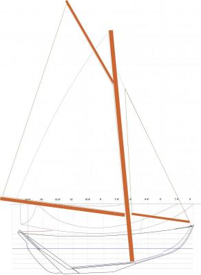
Hi Bob, Yes you are absolutely correct I did an overlay of the 12 1/2 original sail plan and you can see that it is forward and scaled up is not quite as large as the one I had put on. sail plan 3.pdf michael

-
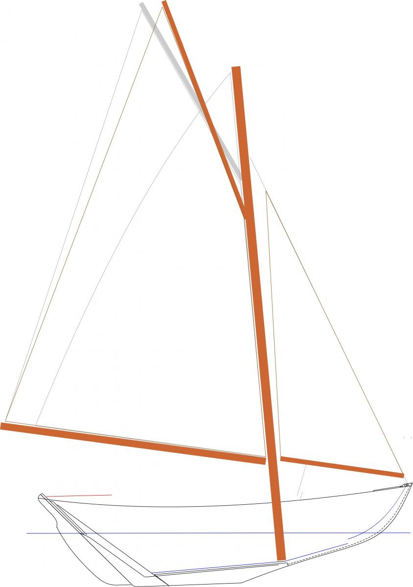
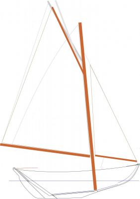
Druxey, the reason i raised it a little was because in reviewing the photo once more that Dan had posted on his blog I noticed that the gaff was pretty much the same angle as the forestay, I could split the difference and see how that looks because I tend to agree with you. This is a better configuration I think Michael
-
Thanks Druxey, and thank you as well Mike for the tip about the CD cases, I shall have a look at that. Michael
-
Mark, I think that the hull looks great. I am not sure that boxwood would look as warm and mellow as what you have achieved. Michael
-
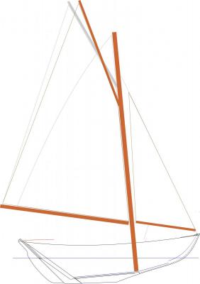
Hi Patrick, The other thing that I particularly like about the gaff rig is the lower Centre of effort of the rig. I have tweaked it just a little, by lowering the gaff jaws and raising the peak this moves the CE just a little forward as well without changing the sail area by any significant amount. sail plan 2.pdf Michael
-
Based on the comments in the wooden boat article by Dan O I have drawn the new sail plan thus. the jpg is 50% PDF full size for model sail plan.pdf Michael
-
Beautiful workmanship John. enjoy the holidays and merry Christmas. Michael
- 745 replies
-
- 3
-
-
- francis pritt
- mission ship
- (and 1 more)
-
This is a great series of pictures on the construction of a full size hull and of pouring the lead keel which had an all to familiar ring to it. this relates to the boat in the previous post. Michael
-
Thanks Pete, I have been thinking about the sail plan and thought that this rig from DanO on the wooden boat forum is the one I would like to adopt, I read Dan's reason for the gaff rig and liked what he had to say. scroll to the bottom of the page to read the reason. Michael
-
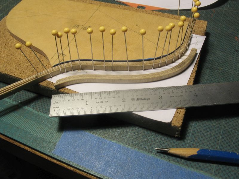
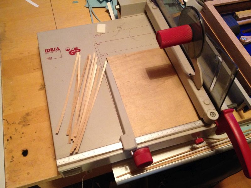
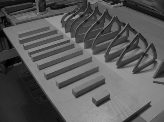
Thanks for all the views and comments and likes. Build Part 2 The laminating of the frames continues, if you ever get the chance to pick up one of these for cheap or even free which is how I got mine grab it, they are amazing paper cutters. And as you can see they do a great job on thin aircraft ply as well. The laminating of the frames continues alongside other seasonal tasks I am waiting about 3 -4 hours before pulling the frames off the form then leaving a full 24 hours before doing any sanding. I have two more stations to go the one at 9' and the one at 6'. Once all the frames are laminated I will set up and fret out the centre sections, I will need to do this out in the shop where it will be a little easier than at the desk. The stations will then be set up on a board to receive the stern post keel, and stem elements.I will also carve a block once all the planking is done and fair it so as to make a mold for the lead keel. If I don't get a chance to wish everyone a great Christmas holiday and any other forms that are celebrated at this time of the year. Judy and Me wish you all Merry Christmas Michael