gak1965
-
Posts
725 -
Joined
-
Last visited
Content Type
Profiles
Forums
Gallery
Events
Everything posted by gak1965
-
 Looking great! Fabulous brass work there. George
 -
I'm also for the thinner thread. Also, FWIW, the line dimensions printed on the plans are circumference, not diameter. You may have already corrected for that, if so, my bad. I used boring, black, mercerized cotton sewing thread for my ratlines. Visible enough, but not too visible, and I found that it hung and tied better than the (I think polyester) line supplied by the kit. Regards, George
-
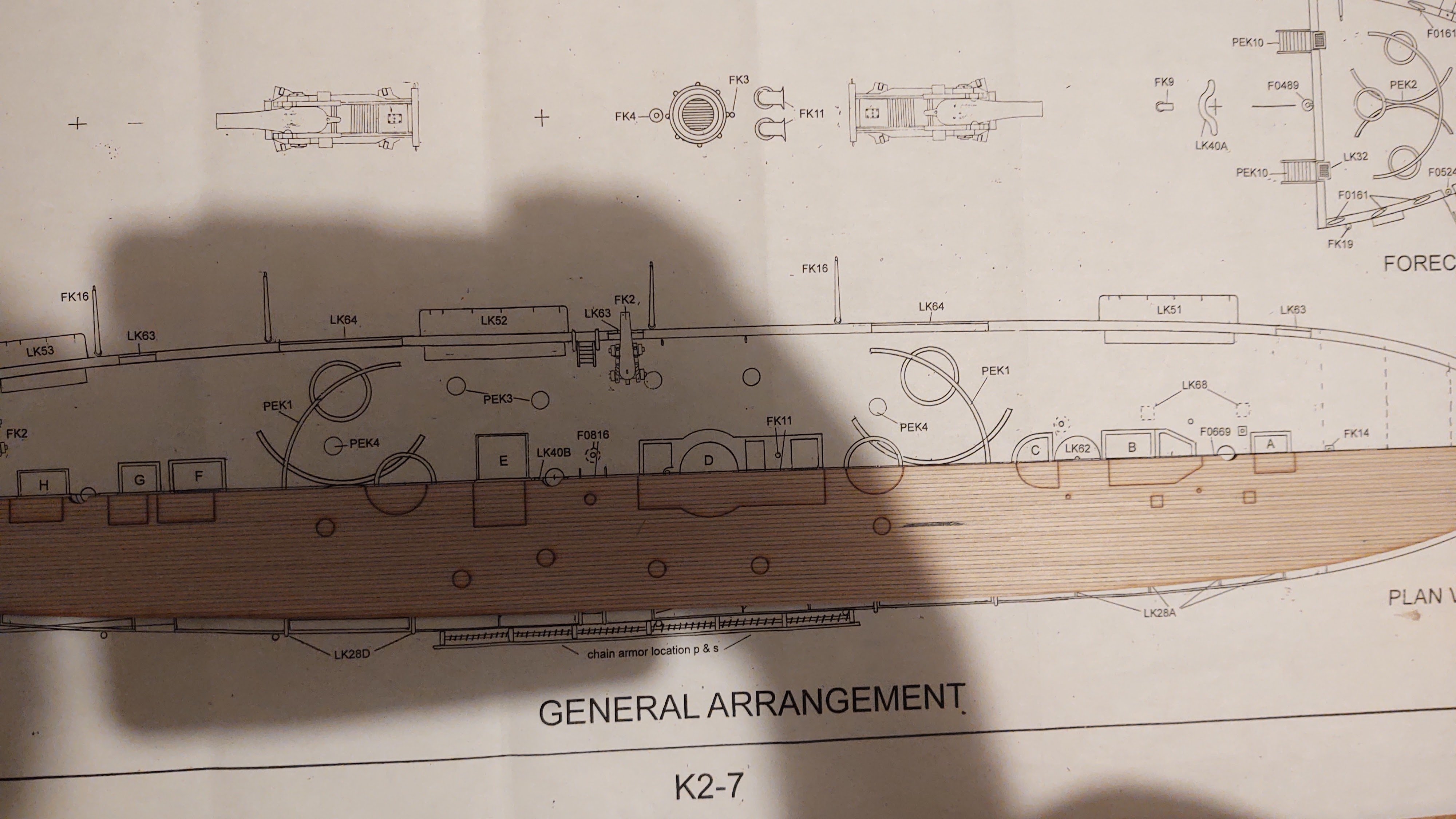
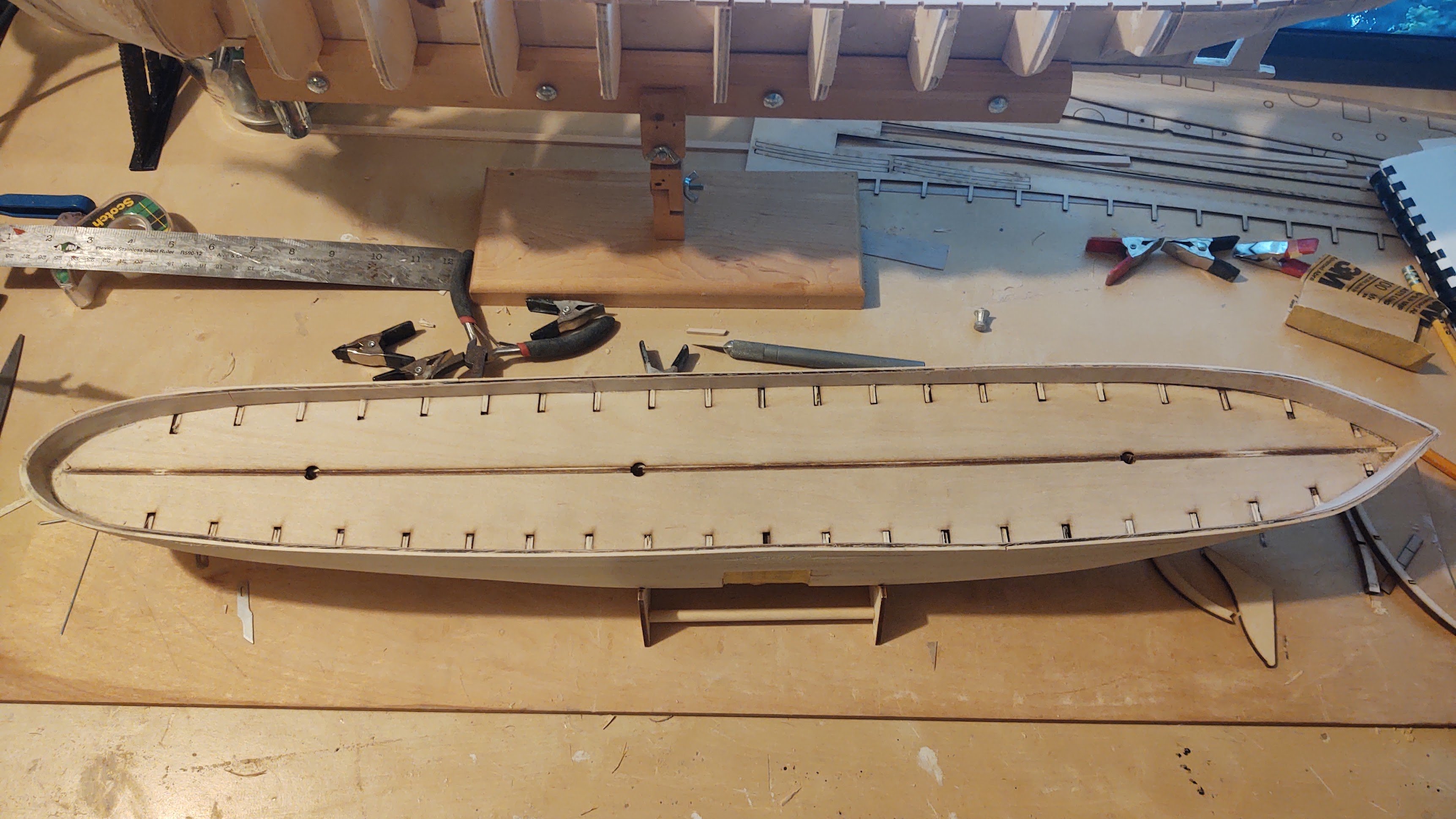
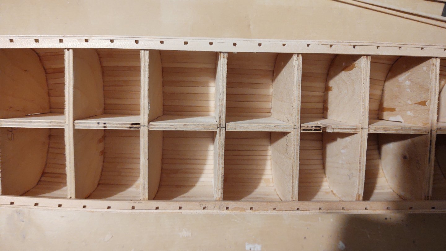
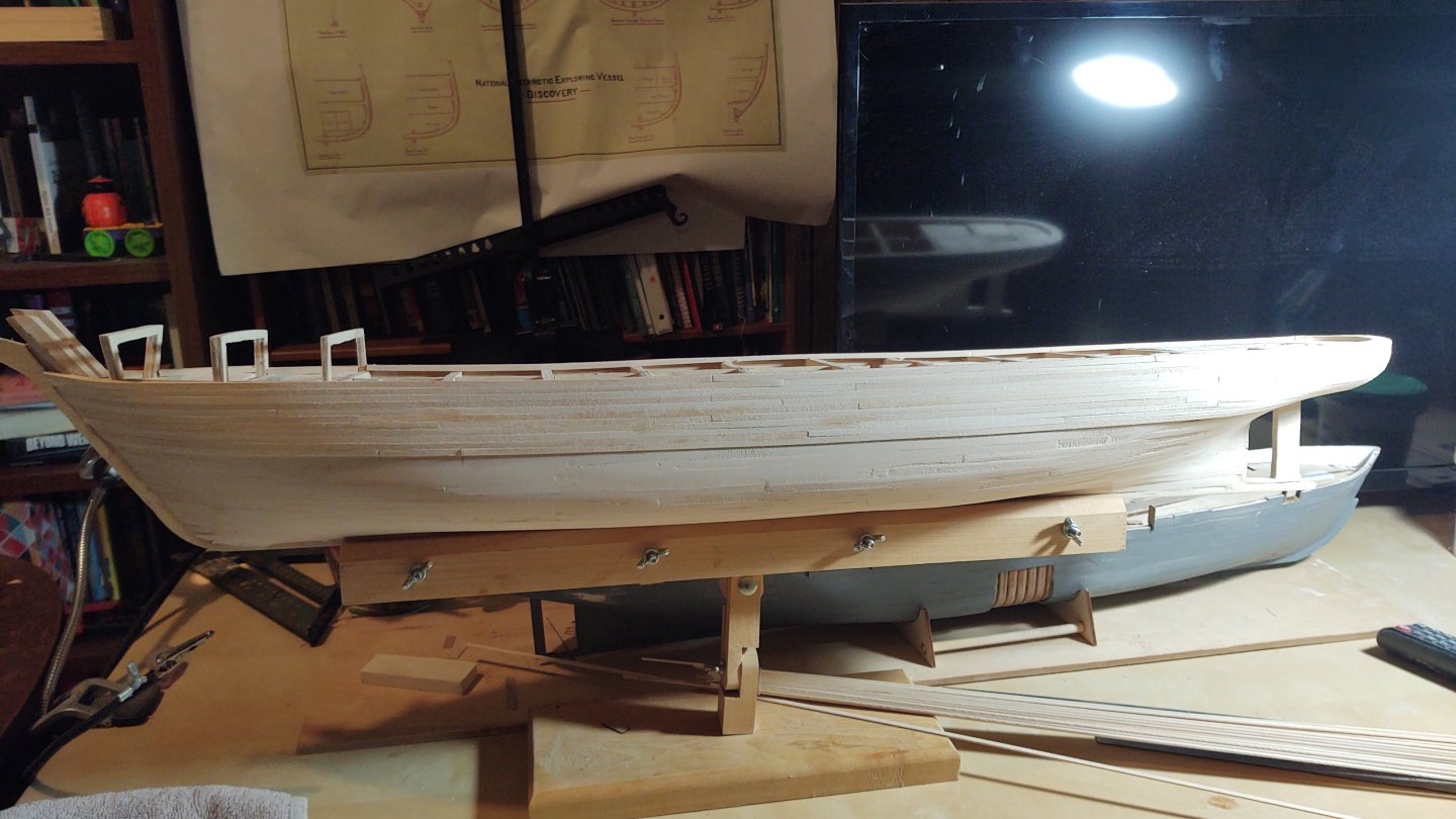
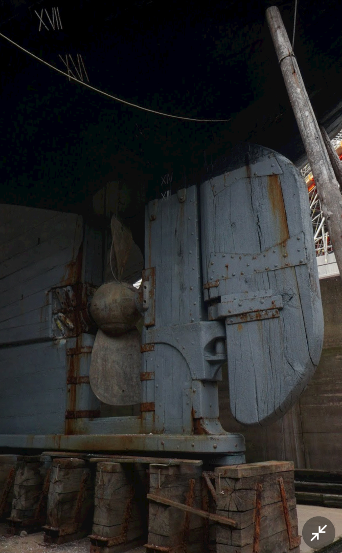
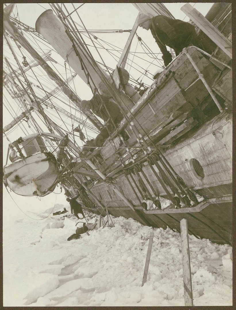
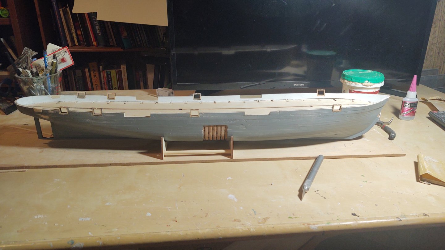
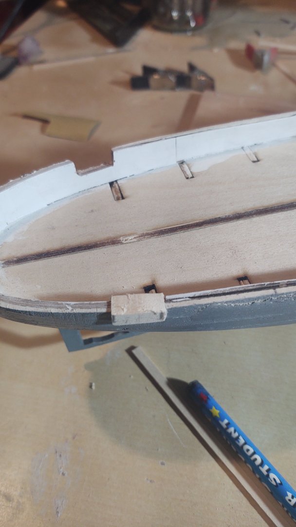
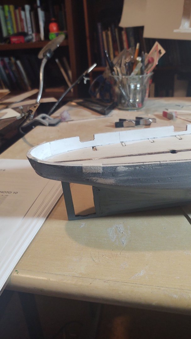
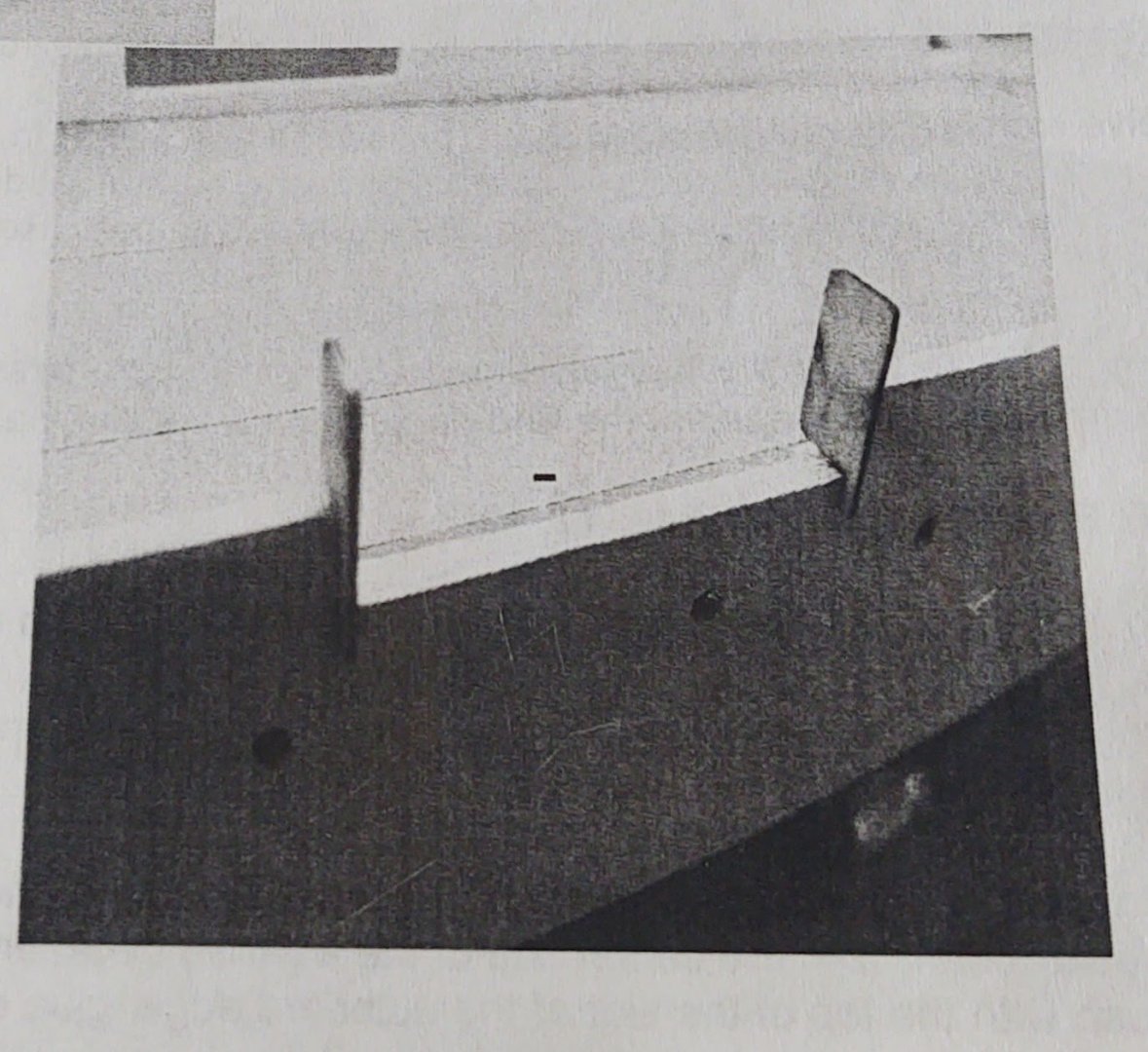
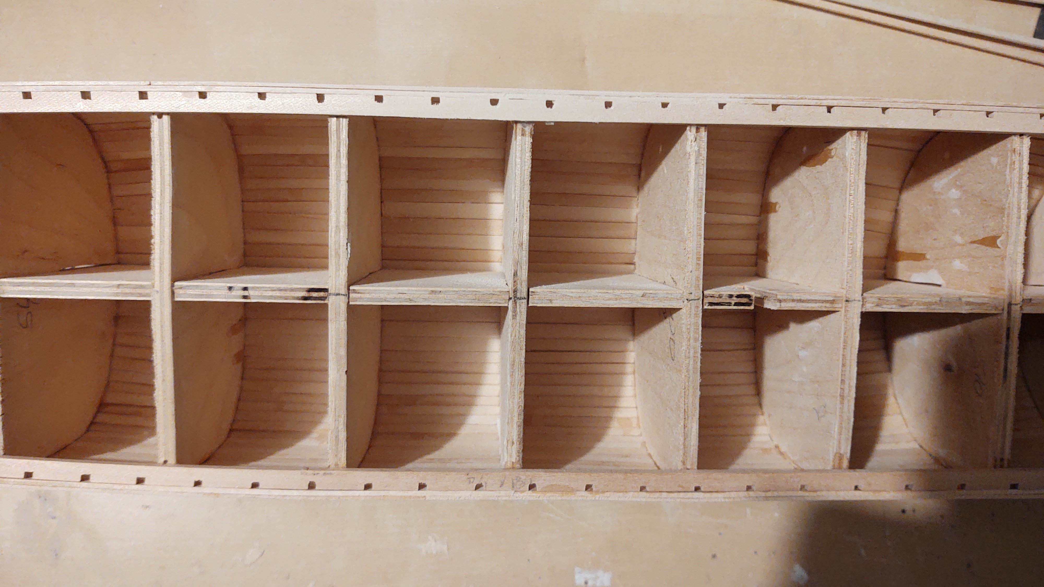
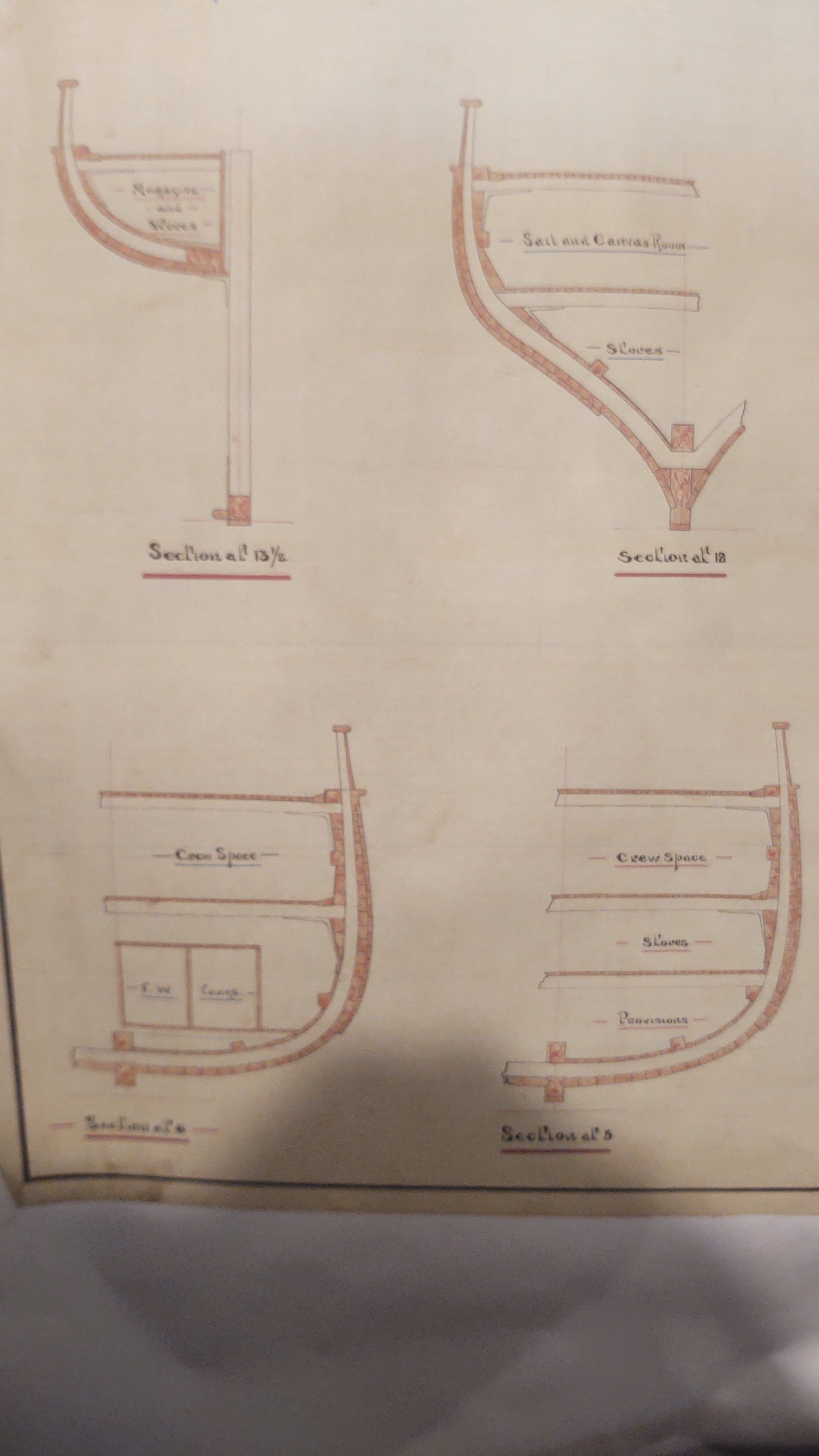
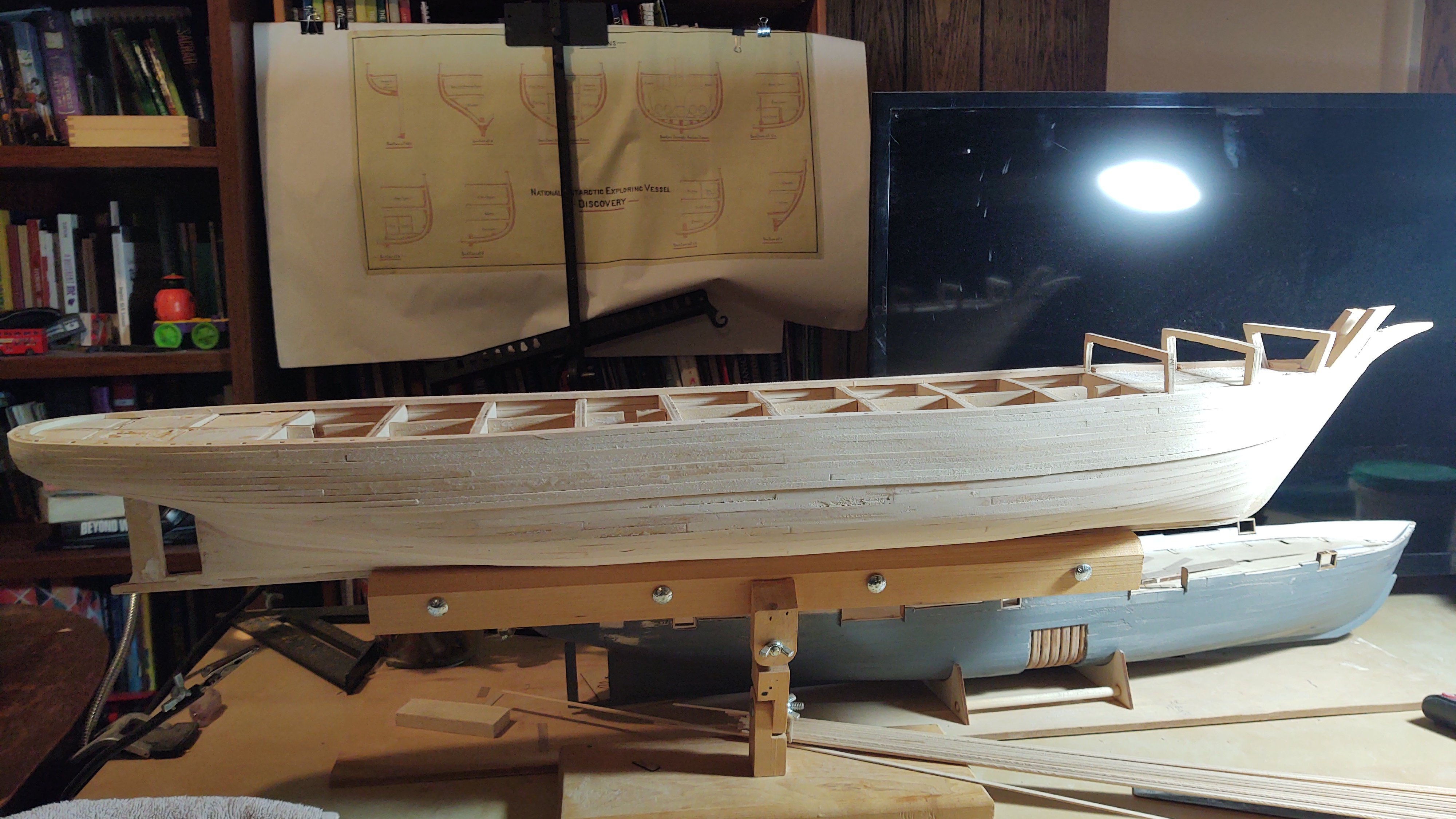
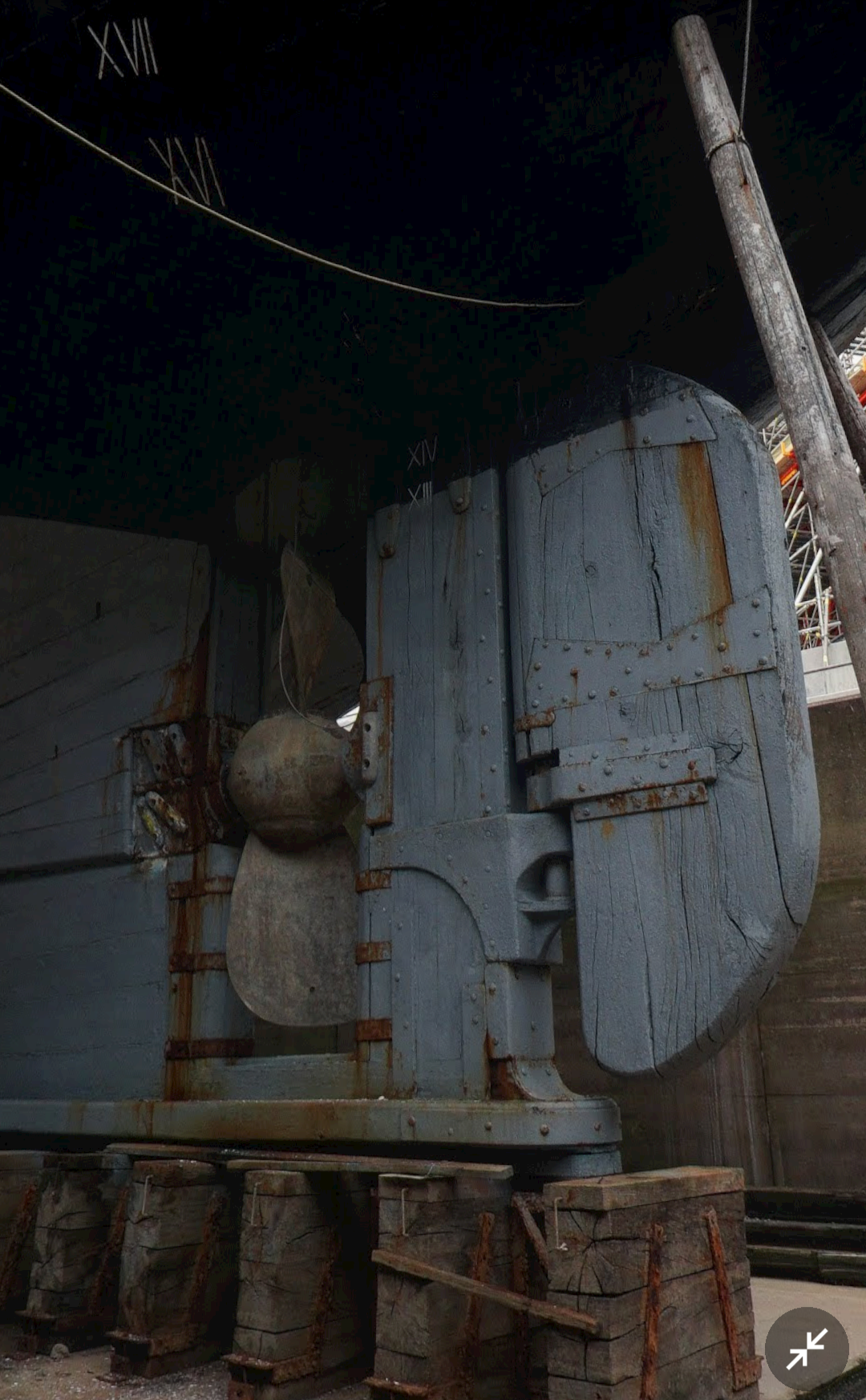
Thanks Bill. I find them to be interesting subjects as well, and Discovery seems to have been overshadowed by Endurance. Wisborough Green eh.... luckily for you, beyond telescope distance 🙂. Haywards Heath You gentlemen have now improved my geographical knowledge of Southern England by at least 2X, just by looking up the locations you reference! On to an update +which has been a while coming). The wood arrived for the next couple of steps. As I've mentioned, the Discovery has a double hull over portions of the ship. You can see it on this photo of the plans. The exact point where the double hull ends varies by frame (which makes these cross sections very useful), with the bow covered from sheer strake to keel (sensible since it has to break ice) but the stern only covered as far as the bottom of the prop shaft as seen here: I'm working on where to put the exact line for the bottom of the double hull, as the drawings and this photo seem a bit in contention, but we'll resolve. In the meantime I've started to put the upper strakes on: And to get the part of the ship that won't be double bulled to a decent finish. Once the double hull is in place, I will be adding a 1/16 square piece of wood to the top of the upper strakes, which will replicate the shape of the actual ship at that location. Then it will be the bulwarks. As you can see from this top photo, the planksheer has holes precut to accept 1/16" stanchions. The sections will drive the ange that they are inserted, and I have some thin (1/32") wood to make the bulwarks from. As always thanks for the encouragement and for looking in. Regards, George PS: @Kevin-the-lubber and @KeithAug, I will be in your part of the world in December. The admiral and I are taking the QM2 from Southampton to New York for our 60th birthdays.


-
Looking good Jared! I didn't bother with clove hitches, too much bulk, too hard to get the line to hang right. Simple overhand knot, using a piece of paper with the pattern behind the lines. Regards, George
- 431 replies
-
- 1
-

-
- Flying Fish
- Model Shipways
- (and 2 more)
-
Looking really great Rick! The chapeling may look different because of photo angles and/or paint. They certainly look great to me, and your yards are works of art. Regards, George
-
A bit of an update. The next steps were to cut the slots for the channels/pinrails and to install the sheaves aft of the final gunport, both of which are completed. In theory, the next step would be to put the deck down, and then installing the waterways. Unfortunately, if you do that, you wind up having to mask the entire deck during the painting process, which strikes me as odd. As a result, I decided that I would build the hammock nets and finish the basic hull and get all of the hull painting done before installing the main deck. Step 1 is to build the hammock netting, starting with the stern and moving forward. Based on the instructions and photos of the ship, the netting should be flush with the outer hull and extend slightly over the bulwarks on the inner side. The nominal interior width is 3/16 inches with 2 1/64 inch sidewalls for a total width of 7/32. In practice, the spacers/end pieces are slightly less than 3/16 so in every case I've needed to narrow the 3/16 wide bottom pieces to some degree or another. The instructions are clear that the rear nets in particular are vertical, and do not follow the flow of the bulwark outward. Progress so far as in the pictures below: In the picture below, you can see the sheave on the port side, and the slot on the starboard side for the aft channel/pinrail under the hammock netting between the gunports. I have to say that the ship (not the model, but the actual ship) seems strangely designed to me. The nominal height from the deck to the top of the hammock netting is about 6 feet, with the bottom opening of the gunport about 2 feet off the deck. That means that the bulwark height is only about 4 feet, with another 2 feet (1/4 inch at scale) of hammock netting. The bulwarks would have extensions of the ship's frames and two layers of planking to protect the crew, the hammock netting only has some thin planks and the bundled hammocks, which means that no one is particularly well protected. I would also note that the gunport frames extend above the bulwarks, without anything akin to a covering board or equivalent to provide additional strength. Perhaps the conclusion was that the guns of the day were so powerful there really wasn't meaningful protection to be offered (indeed using chain armor was key to the Kearsarge's success), but still, it feels kinda odd to me. Anyway, I'll be making these things for a little while, and will also put in the sally port ends before turning to the rest of the hull. Regards, George


-
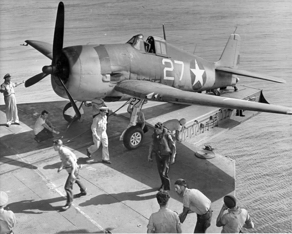
Not sure which ship this is (Enterprise, Hornet, or Yorktown) but a good photo of the cross deck catapult. Carrier aviation is a specialist activity. Launching through the hanger is plain (hah!) insane.... Regards, George
-
Wow! How are you making these amazing parts? I gather you are a machinist, but still, wow! George
- 68 replies
-
- 3
-

-
- Coates
- Rudderow-class
- (and 1 more)
-
Hi Tom! I know that this is a month out of date, but your channels seem spot on vs. the directions. Here is a photo of Endurance that shows the channels and it is pretty clear you did it right Regards, George
- 206 replies
-
- 2
-
-
- Endurance
- Shackleton
- (and 2 more)
-
Well, a bit of an update. If you look carefully at the photos in my previous entry, you will notice that somehow I managed to put the aftmost gunport in the wrong place. It's way too far aft - I apparently misread the marks that I put on the bulwarks that indicated where it was supposed to go. 100% my goof. So, repairs commenced. I cut out a bit of wood, fitted it to the gap: Sanded to match the curves of the bulwarks: Rinse and repeat on the other side: Once the paint the hammock nets are in place, you'll never know it was there. Annoying, but completely on me. I've since cut the correct gunports, and mounted the 10 gunport frames. Thank goodness for having 10 to fill 8 slots, as two of them were destroyed sanding them down to the thickness of the bulwarks. The trick is to leave cut the center piece, but leave it in the frame as you sand. Put the pressure on the frame as much as possible so you don't have to sand down a solid piece of wood, but it keeps the pressure off the relatively delicate piece of wood that is the frame. As you might have guessed, the answer to my question above was to sand the frames to the thickness of the bulwarks, and I've pretty much concluded that the parts are just mislabelled as I mentioned. So, next step will be to add the frames for the large pivot guns, and then I think it's time to start cutting the slots for the channels and building gunport nettings. Thanks for looking in everyone! Regards, George


-
On my 1:96 Flying Fish, I used 1/16 square stock to make the stanchions. It wasn't really an option not make them, they were what I was going.ti build the bulwarks off. The stanchions on the real ship were extensions of the frames, so did have non square, non straight profiles, but at 1:96 on (in my case) a POB ship it made no sense to try to shape them. I did include the ventilation tubes. I'm a little surprised they are straight on the plans. The Fish plans had them turn over so that the opening faced down, presumably so that it would be a little harder for water to enter Regards, George
- 199 replies
-
- 1
-
-
- Flying Cloud
- Mamoli
- (and 1 more)
-
Not an update per se, but as part of a restoration, a group sponsored by Dundee Heritage (which manages the ship) had a high resolution 3D model of Discovery built. It's not particularly useful to me, as it is of the ship today (it was made by scanning the current ship), rather than as she was in 1901, and there have been a lot of changes (the masts moved, 5 yards/mast now vs. 4 in 1901, most of the deckhouses changed, etc.). Still, pretty cool, and really useful for anyone that wanted to build the Discovery of 2024. I don't know what they are doing about getting the maps, but you can see a video that they put together here: Regards, George
-
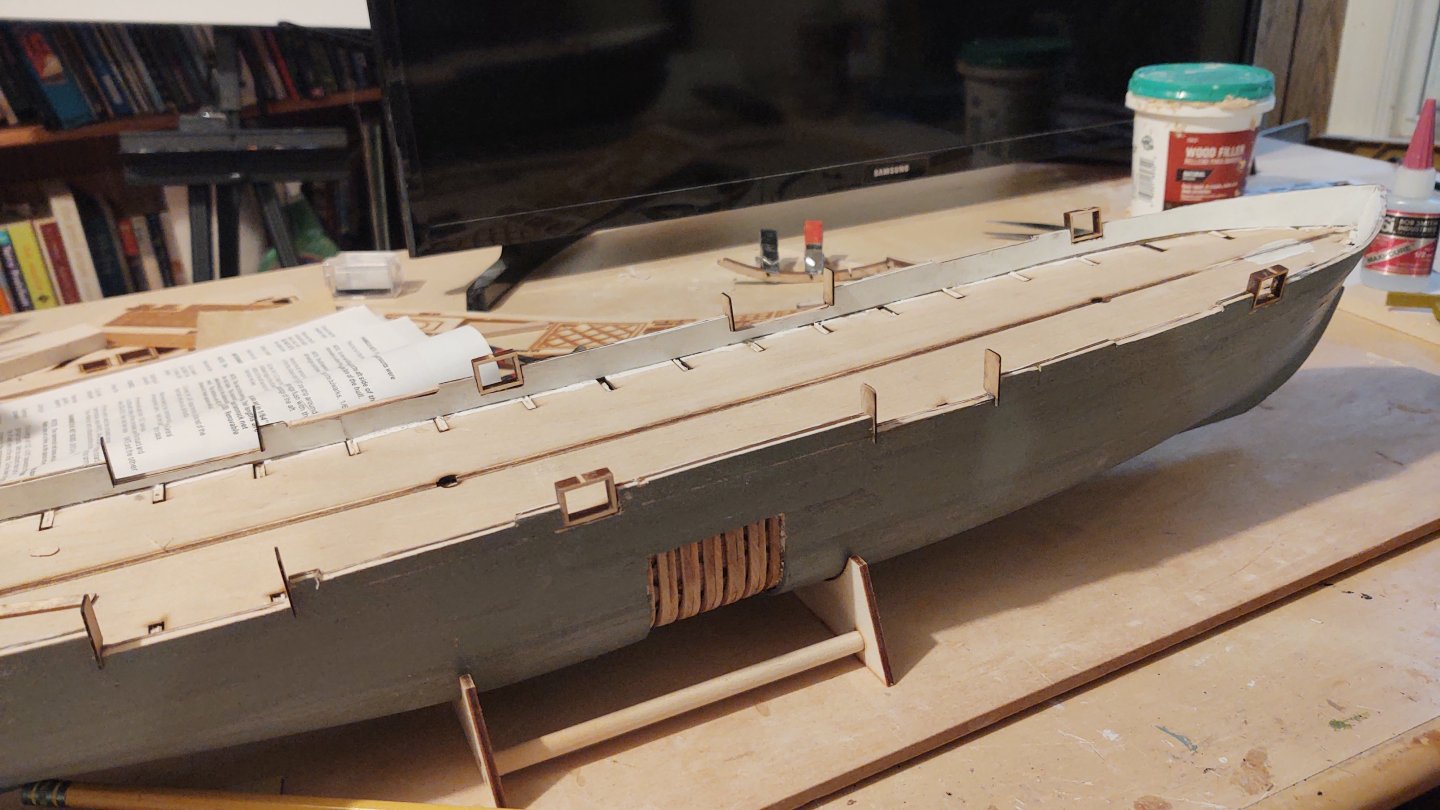
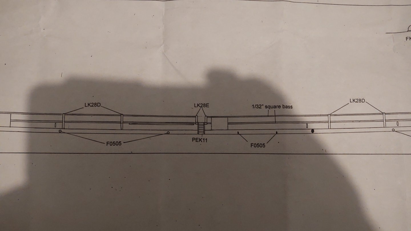
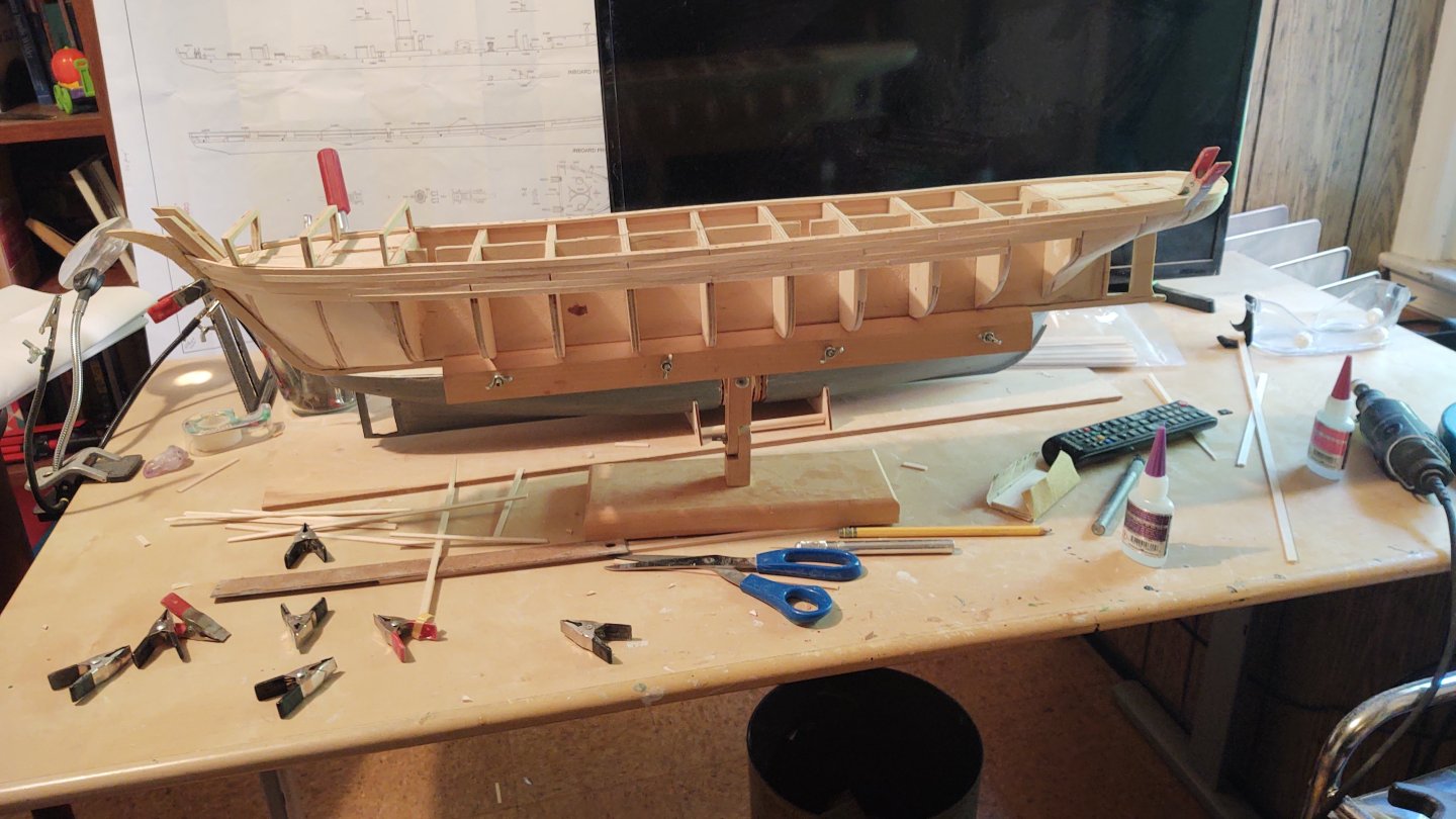
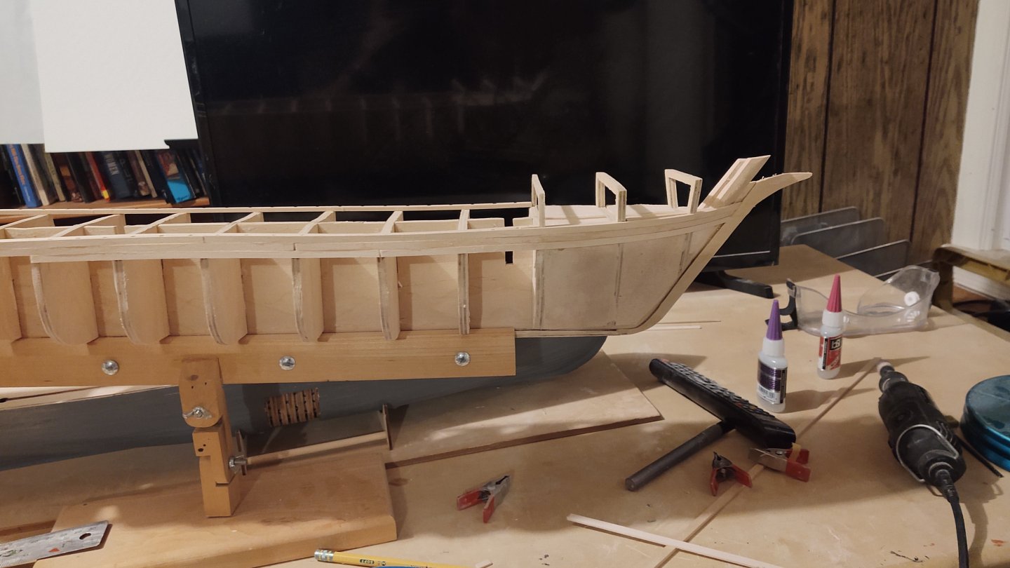
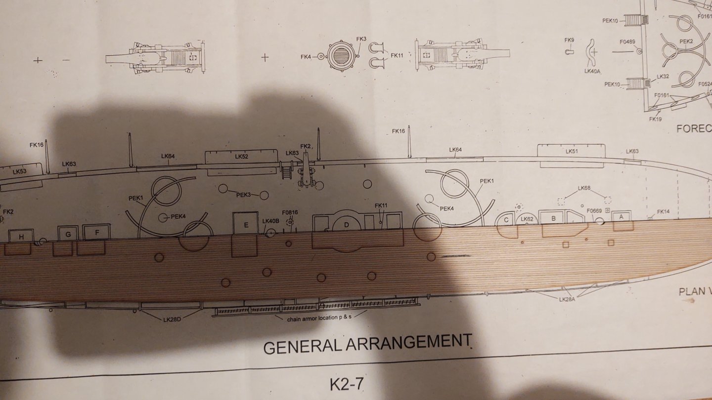
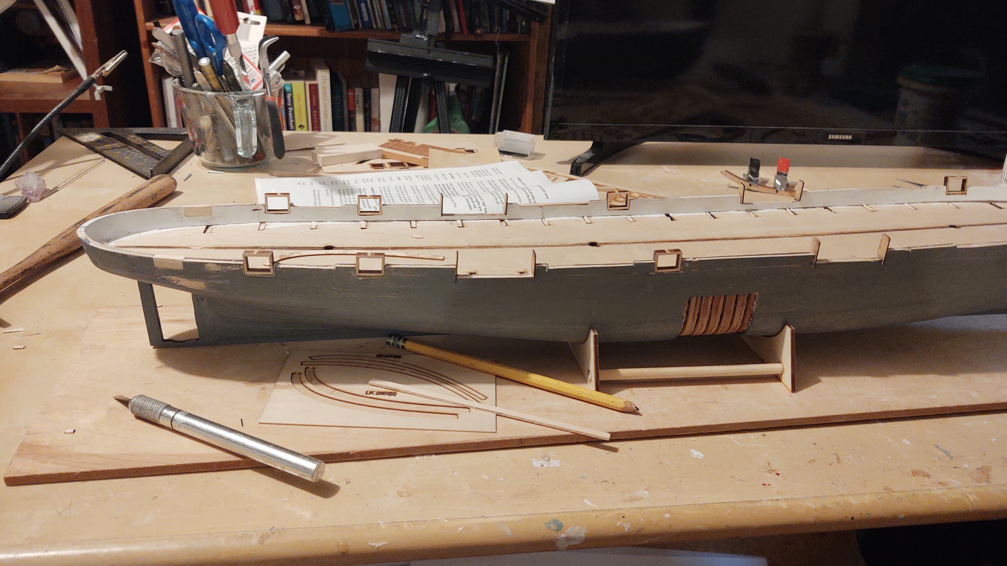
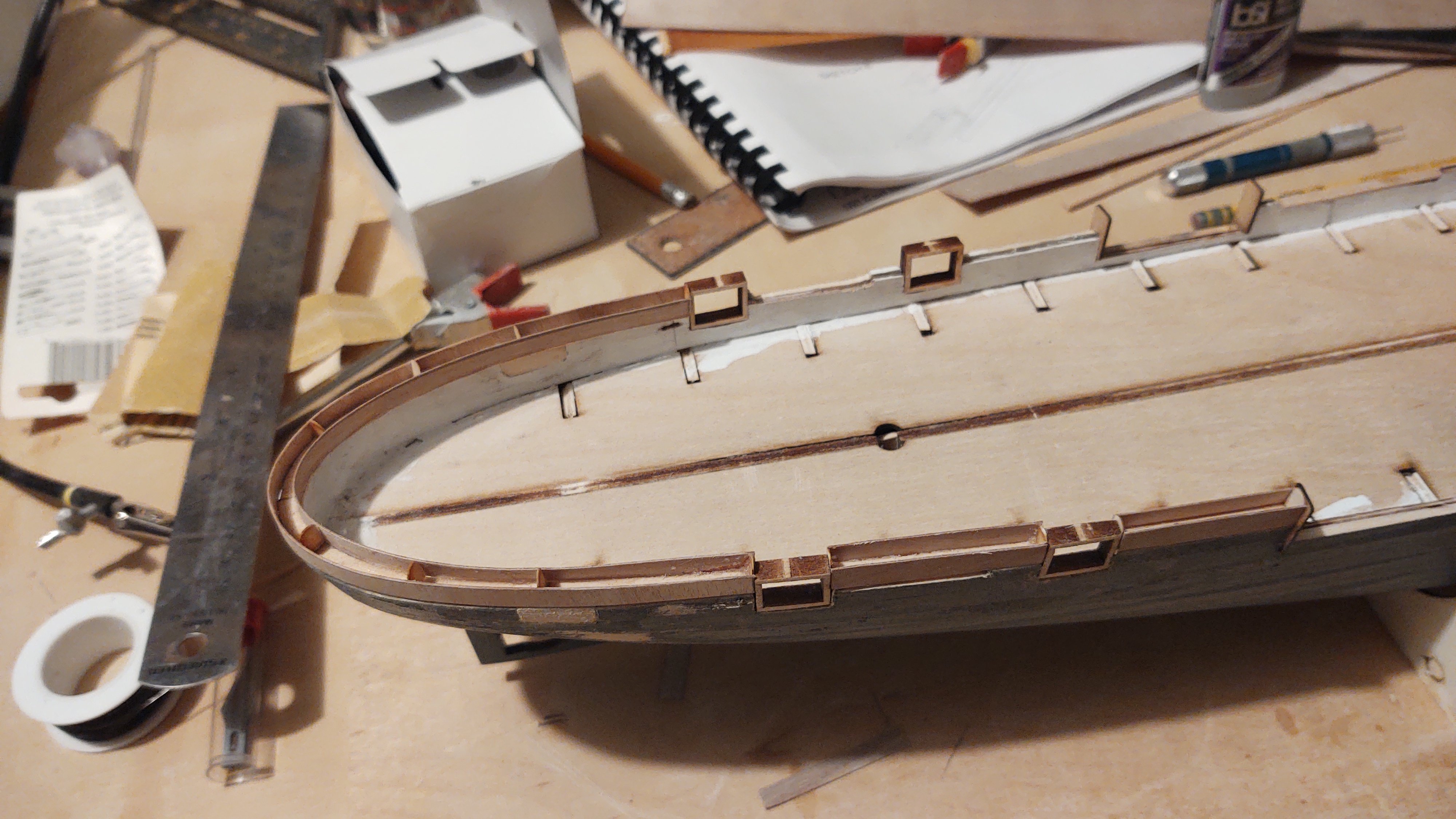
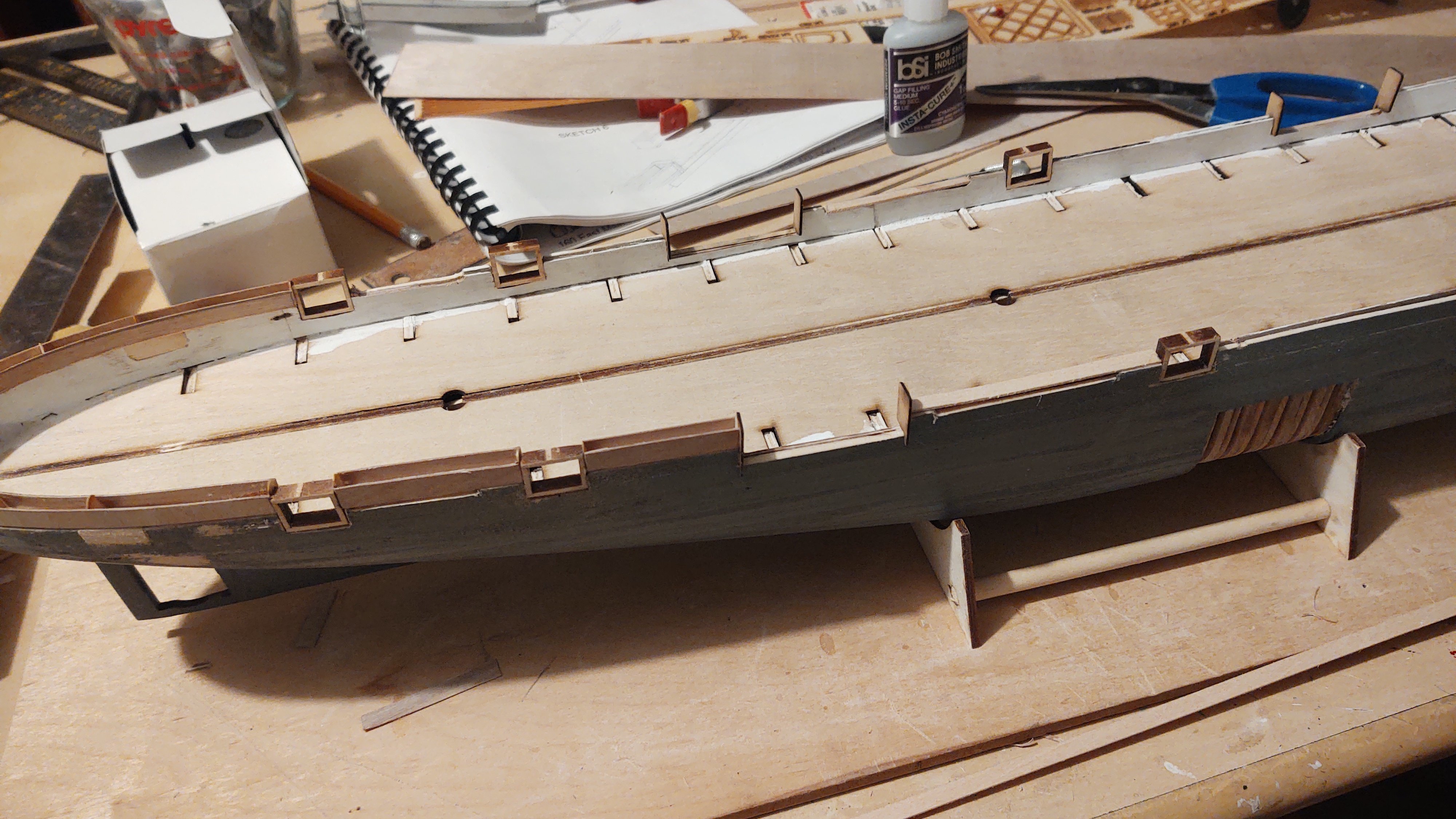
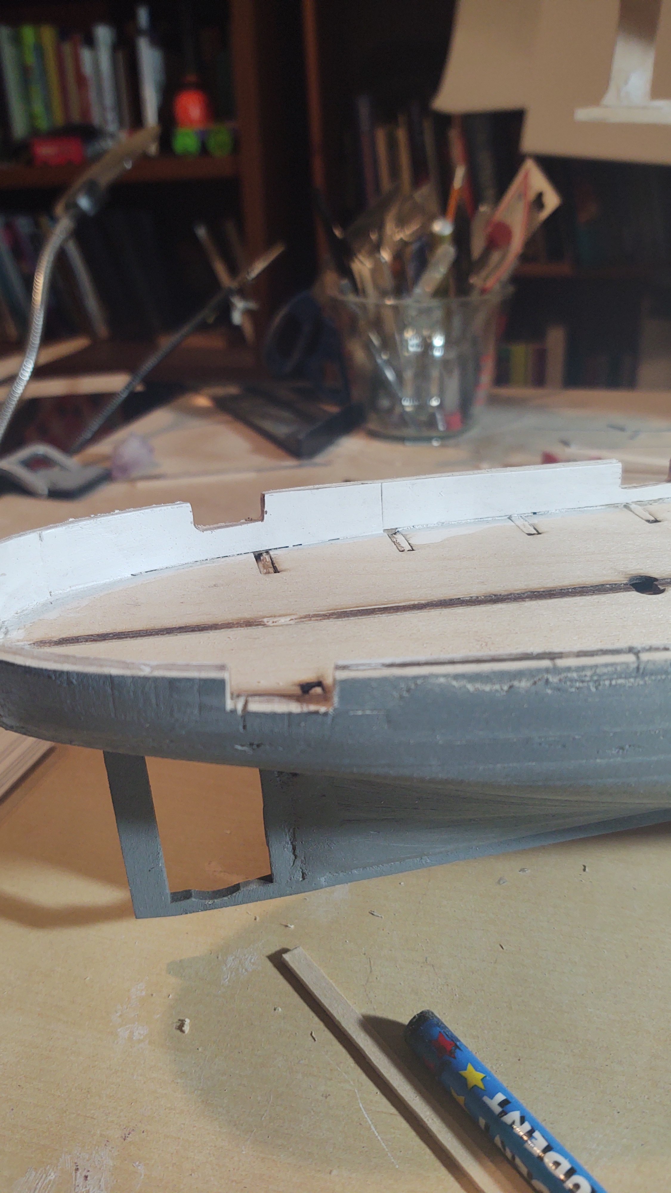
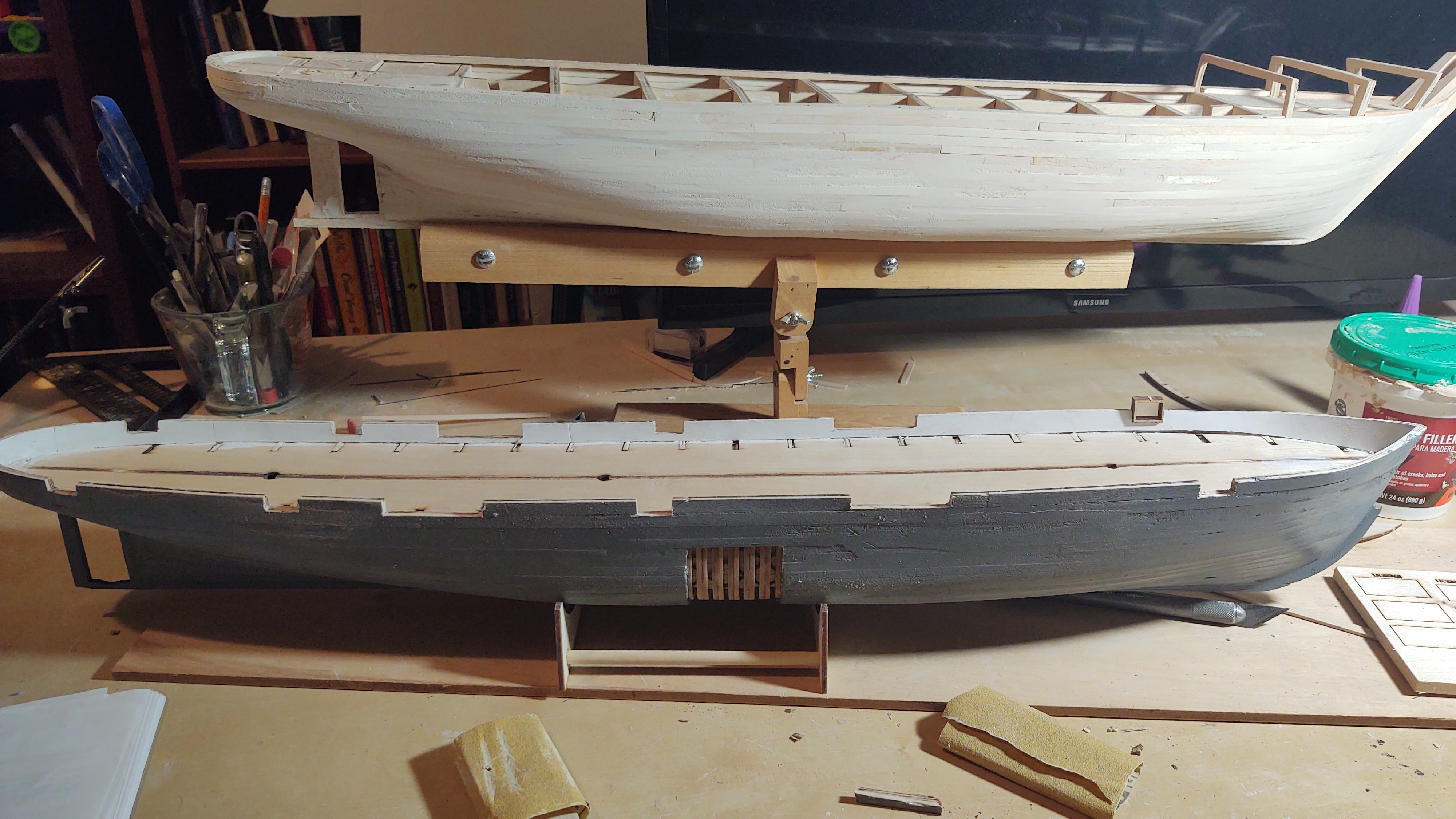
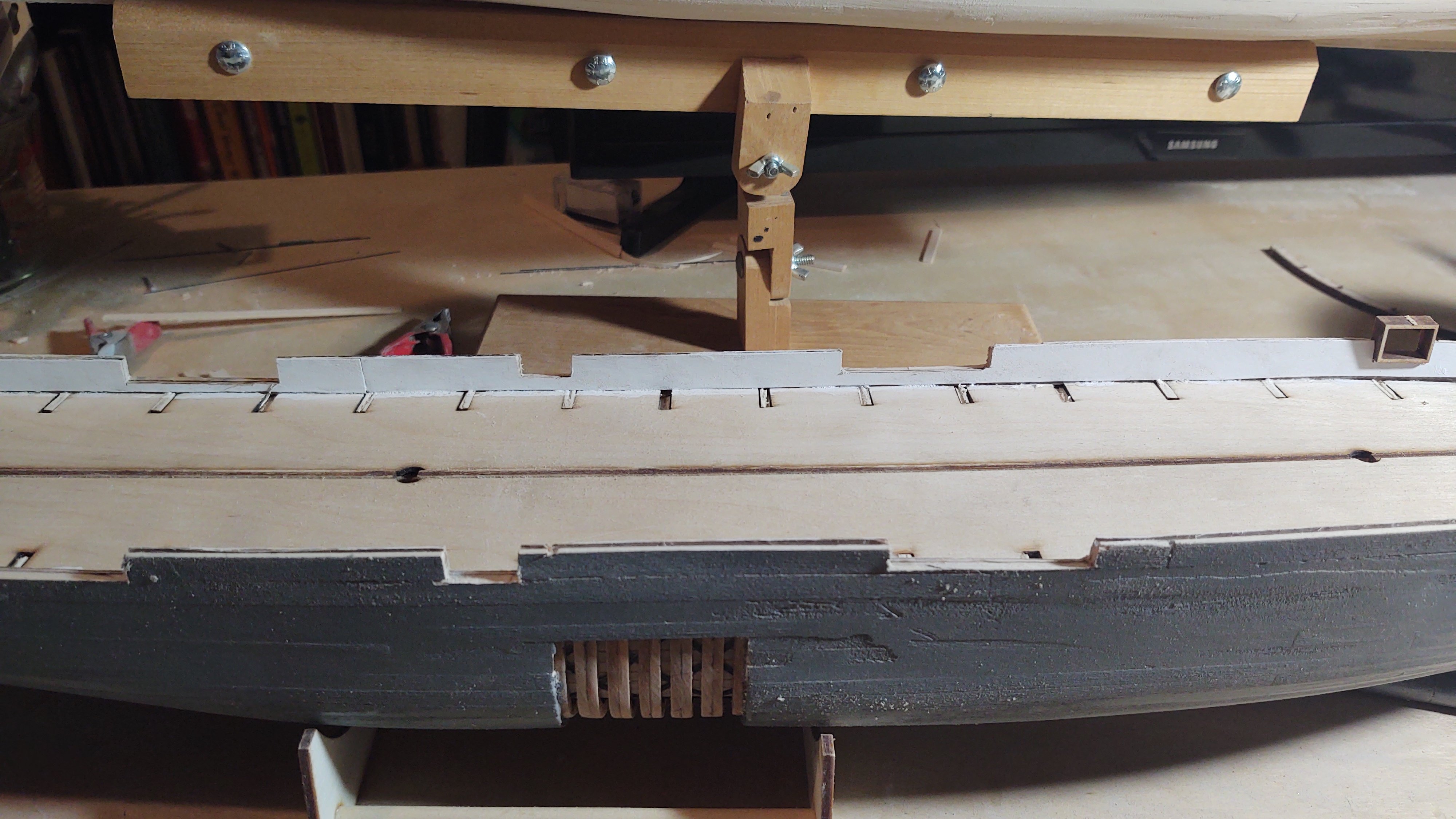
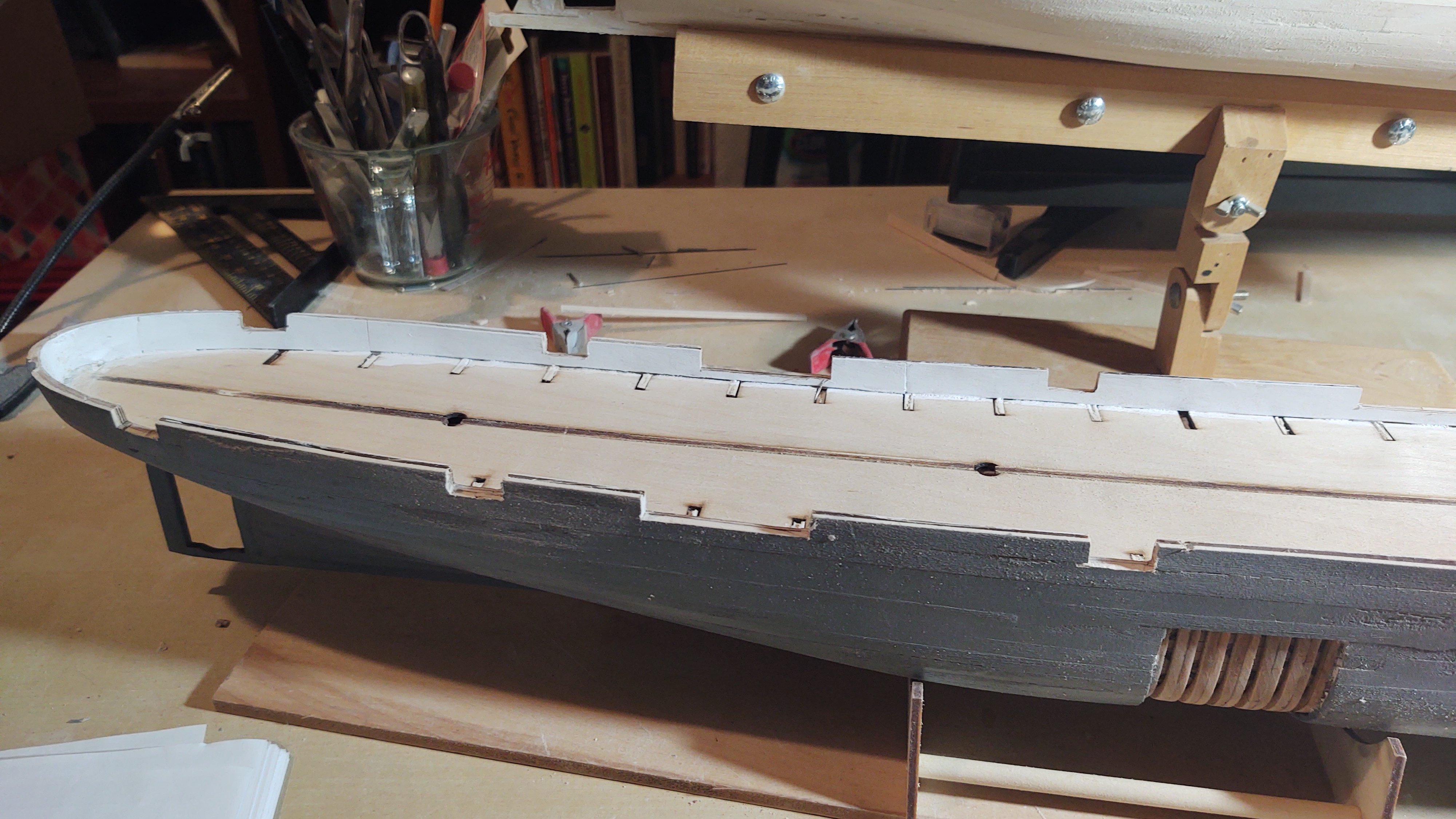
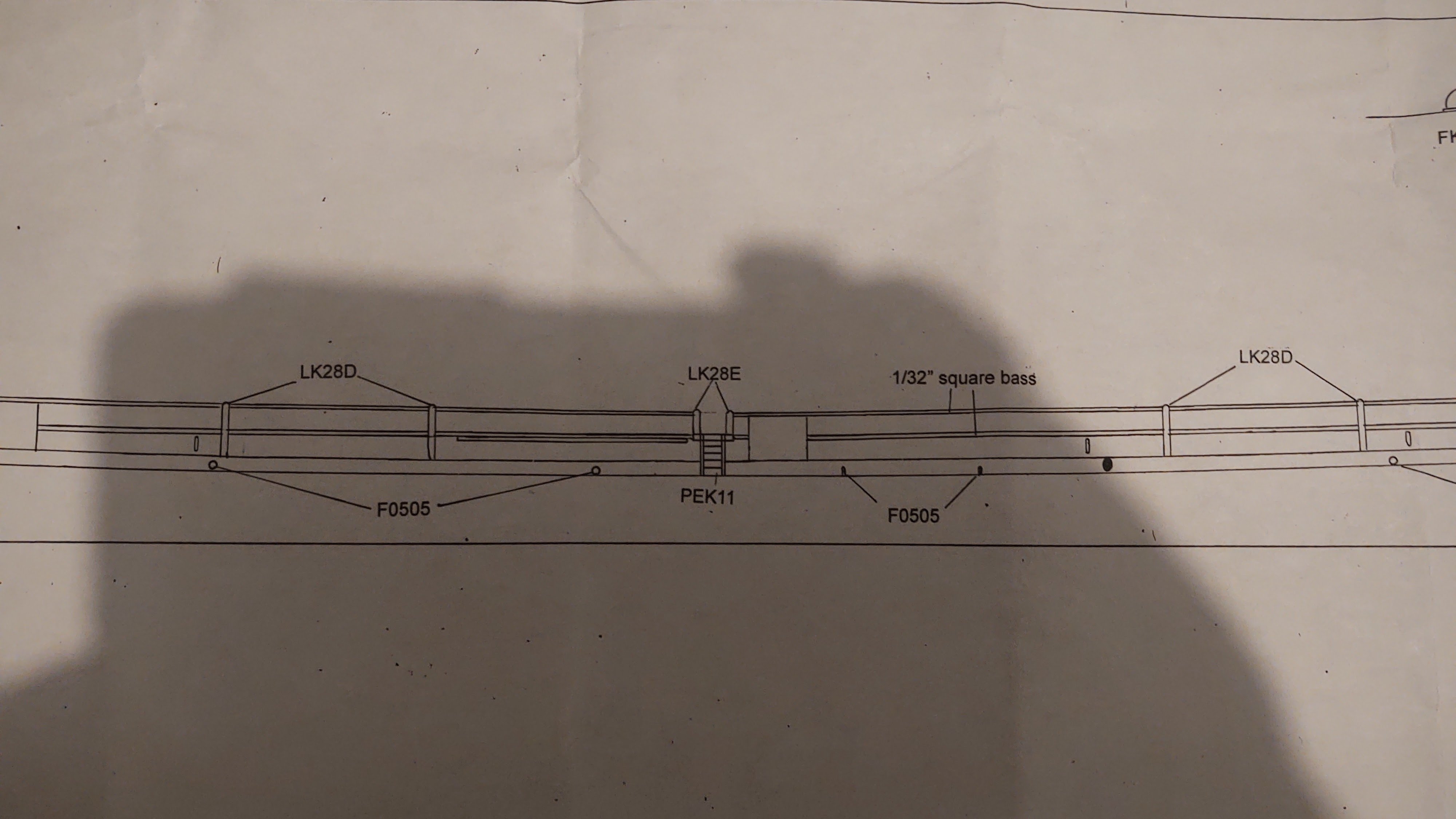
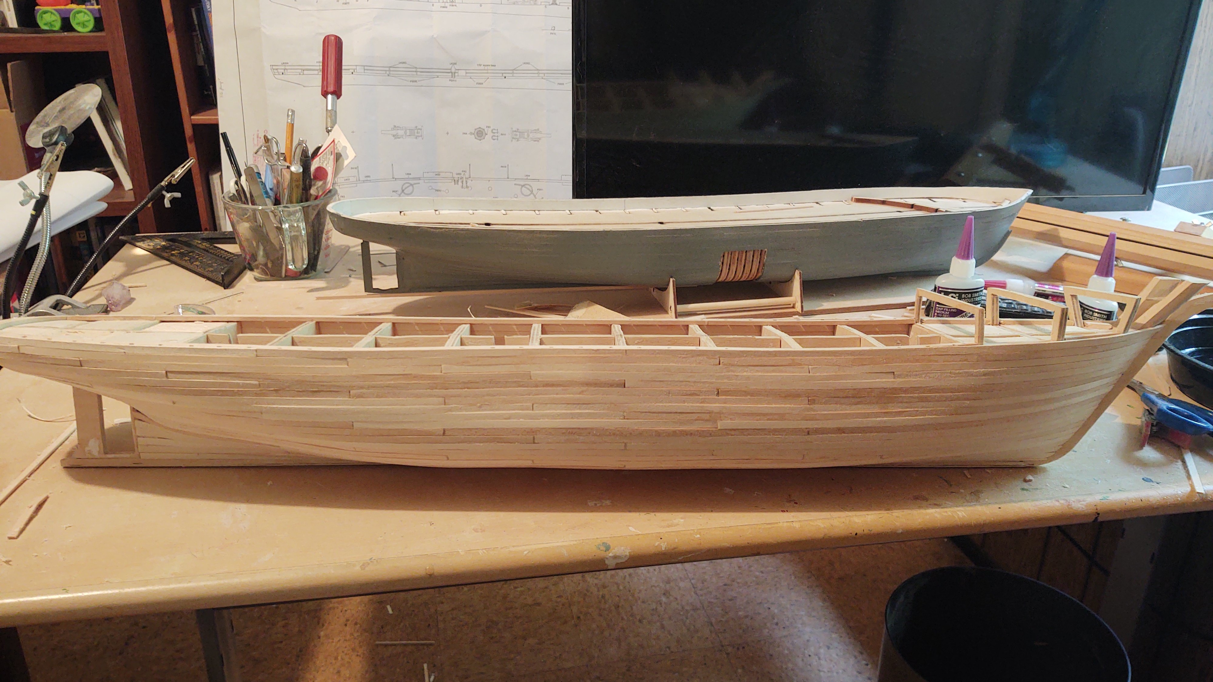
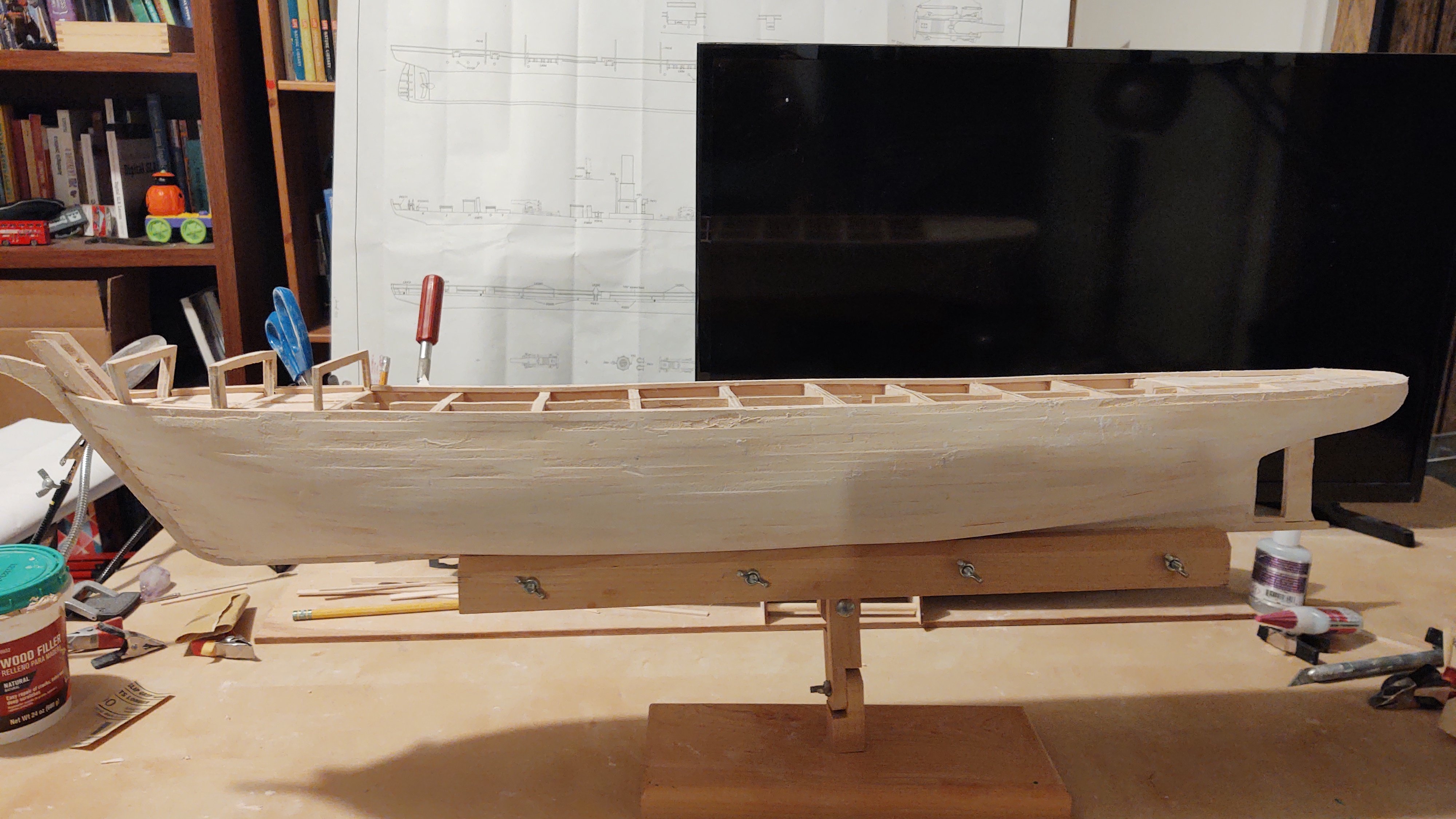
Hello all. I've been running around dealing with a bunch of things (including some work on RRS Discovery and have just recently gotten some time to work on the Kearsarge. I've opened out the gunports as can be seen in the photos below. For the large ones, I used a razor saw to cut the vertical slices and then clamped a metal straight edge to where the bottom cut needed to be, and opened it out with a reinforced cutting blade from my dremel, which worked well. The smaller gunports were done similarly, vertical edges defined by razor saw, and used the cutting wheel to open it out, but more or less treating it like an abrasive. Everything then squared up with sandpaper. I think, on the whole it went well. Ship as a whole (Discovery in the background) awaiting wood for the second planking. And two close ups. However, I could use some assistance from anyone who's built this before (or maybe @MrBlueJacket because I am confused at this point. There are two points of confusion. The simpler one first. The instructions say to put the gunport frames in, making sure that they are flush on the outside of the hull. As you can see from the upper and middle photo where I have one of the frames dry-fitted, the frame is wider than the bullwarks. My natural inclination would be to glue in place, sand the inside so that it is flush with the inner bulwark as well, gap fill with a bit of putty. However, the following sketch is provided for one of the next steps. In it we see the frame jutting into the ship over the bulwarks, trimmed (?) as shown. The instructions don't mention the trim, although they a later photo suggests that they do need to be trimmed down to the edge of the inner bulwarks. Any thoughts welcome. The more complicated question relates to this instruction in the booklet: "Remove the pivot gun (LK28C) and sally port (LK28D) hammock net ends from the carrier sheet. Remove 1/32" from the forward end of each pivot gun port cutout and glue a pivot gun hammock net end (LK28C) in place. Using the large gun port lid (LK64) as a guide trim the aft end of the cutout to its length plus 1/32". DRY FIT a pivot gun hammock net end to the aft end of the cutout and adjust as necessary until the large gun port lid fits tightly between the two ends, then glue them in place. Set the lid aside." "Remove 1/32" from both ends of the sally port openings and glue the sally port hammock net ends (LK28D) in place (PHOTO 10")" Okay, so here is the problem. There are 8 pieces labelled LK28C that look like the parts in photo 10 below. When I look at the plans, they say to use LK28D (which frankly doesn't make sense). Earlier, the instructions indicated that I needed to cut out the sally port openings in the same way as the gun ports, however, nothing on the plan is labelled as a sally port; the closet thing is the port by the accommodation ladder (PEK11 in the diagram). The entry is defined by two ends of the hammock nets marked with parts LK28E. I have no part LK28E, and the part list doesn't list it either. There are 8 part LKE28D (the sally port hammock net ends) but only 2 sally ports, and bottom of what I think are the sally ports is the top of the bulwark, so no need to cut anything out of the bulwarks. So. My interpretation of what I should do is: Make the small gun port frames flush on both the inside and outside of the bulwarks. Use the 8 LK28C parts to frame up the large, pivot gun ports, and prepare them for the hammock netting. Conclude that the marked LK28D parts on the plan is a misprint and use the LK28C parts as above. Use the LK28D parts for the two sally ports in place of the parts marked LK28E on the plans, and hold off doing anything for now, because they would just wind up sitting there. Anyways, thanks for looking in and the likes. I'd love folks opinion on the plan above. Regards, George


.thumb.jpg.a0f07da3f123eeb7c67a9e7f4448f587.jpg)
-
Looking great. I was wondering how to make the figurehead from the pieces and just gave up and made a new one. I also kind of cheated with the bobstay shackles. I drilled a hole in the brass that was mounted on the prow, used that to drill a matching hole in the wood, glued the brass strip in place, and then glued an eyebolt into the lines up holes in the bow and brass. It worked, but yours is more real. Regards, George
-
Sorry Keith. Both my father and in-laws are in their late '80s now, and they have relocated to a senior facility as well. I will say that there are better and worse versions of these places. My in laws chose one that my wife and I both think is, I don't know, less cheerful? Interesting? than the one my parents chose. And the place where the woman my father is seeing these days lives is better than either. I guess my point is this is a time to be choosey. Best wishes, George
-
Jared, Glad to see you back and working on the Fish! She's looking great! Regards, George
- 431 replies
-
- 1
-
-
- Flying Fish
- Model Shipways
- (and 2 more)
-
Well, it's been a crazy couple of weeks, what with my travel, then my wife taking a trip, and for the last 10 days I've been playing nurse as my wife recovers from a procedure. She's fine, but is on crutches and as a result can't really do much around the house, so... Anyways, the inner planking is done. Here she is before putty and sanding: And with the first pass of putty and sanding. Obviously, I have more sanding to do, and some gaps to fill, but not looking too bad. Here is the ship from the bow and stern. Again, needs sanding but starting to look like a ship. Once the surface is in good shape, I can proceed to do the second planking. I need to order the wood for that, so probably a couple of weeks away still, and then I can build up the bulwarks and start thinking about putting some paint on. I am going to paint the whole hull. I didn't order the wood yet because I wanted to see how accurate my estimate for the main layer was. Answer was that it was a little under, so now I have a good correction factor for the second layer. In any case, thanks for looking in and the likes! Regards, George


-
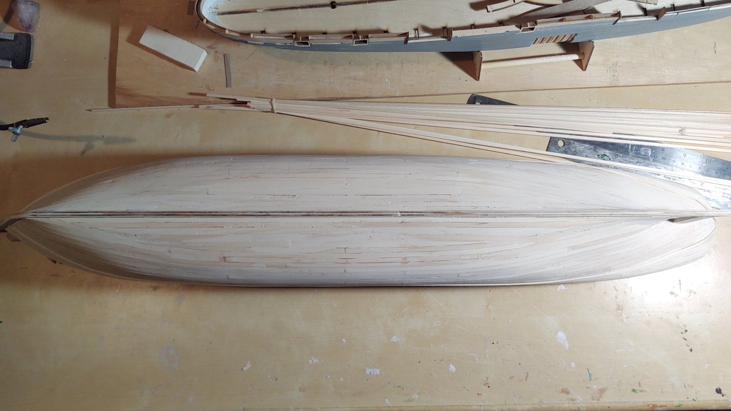
I'm off to the annual American Society of Clinical Oncology meeting in Chicago for the next few days, so no updates for a bit. The "plankers progress" continues. Here she is port and starboard... A ways to go, and then a second planking. The second isn't for aesthetics, the ship had an extra layer of planks over the part of the hull that contacted the ice, but it will still be thinner like an aesthetic double planking. You can see this on this small portion of a photo from Google Maps (source is named Open Virtual Worlds). I find it interesting that it needs stealers, although I suppose I shouldn't be. I also note that while the primary planking aligns into the rabbet near the stern, the second layer does not, and that's good, because I didn't cut the rabbet to handle two layers of planks. Anyway, thanks for looking in and hopefully an update in a week or 10 days. Regards, George
.thumb.png.917ec3c6624f25ef2a622140a60333cd.png)

-
Interesting, the plans for the Fish indicate them being forward rather than TDC. My AOTS for USS Constitution omits the backstays for clarity and Crothers doesn't seem to talk about them.
-
Rick, the blocks and the yards are looking superb! Those gin blocks are a pain in the tush to fabricate, but yours look fabulous. Regards, George
-
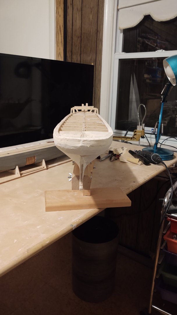
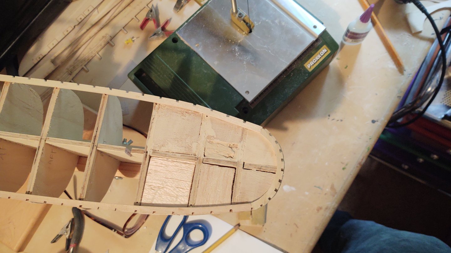
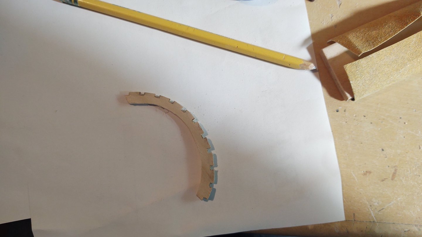
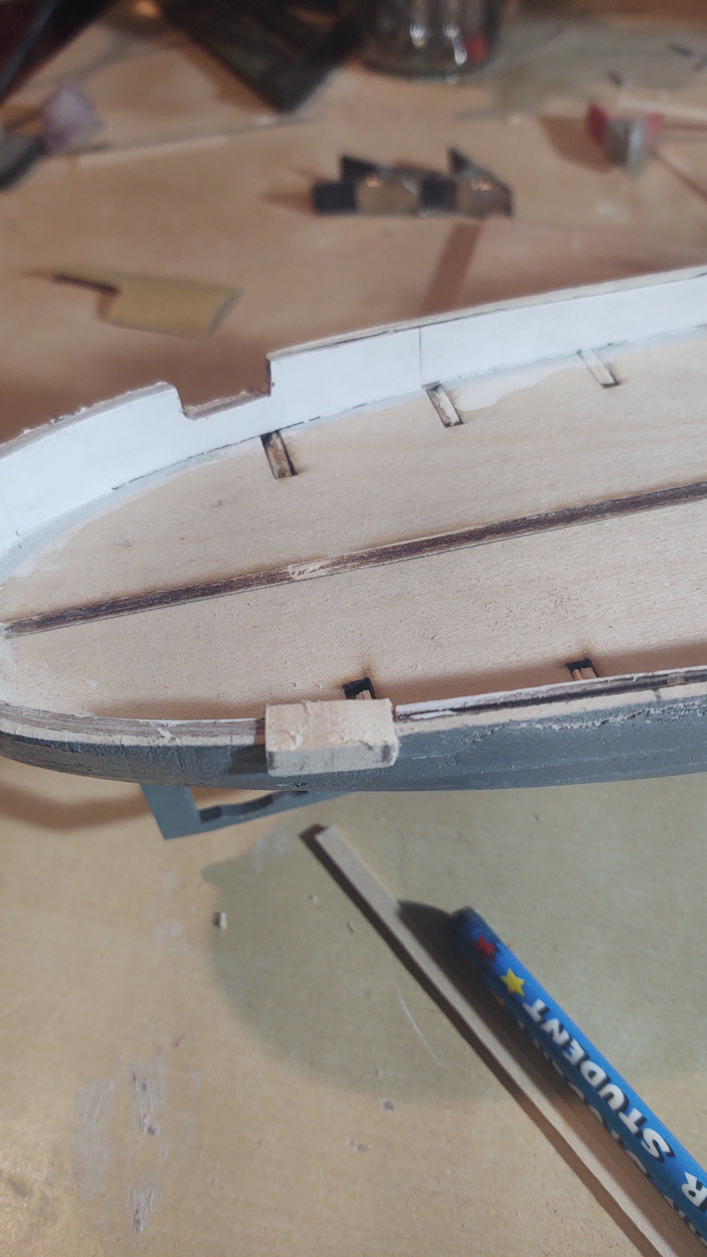
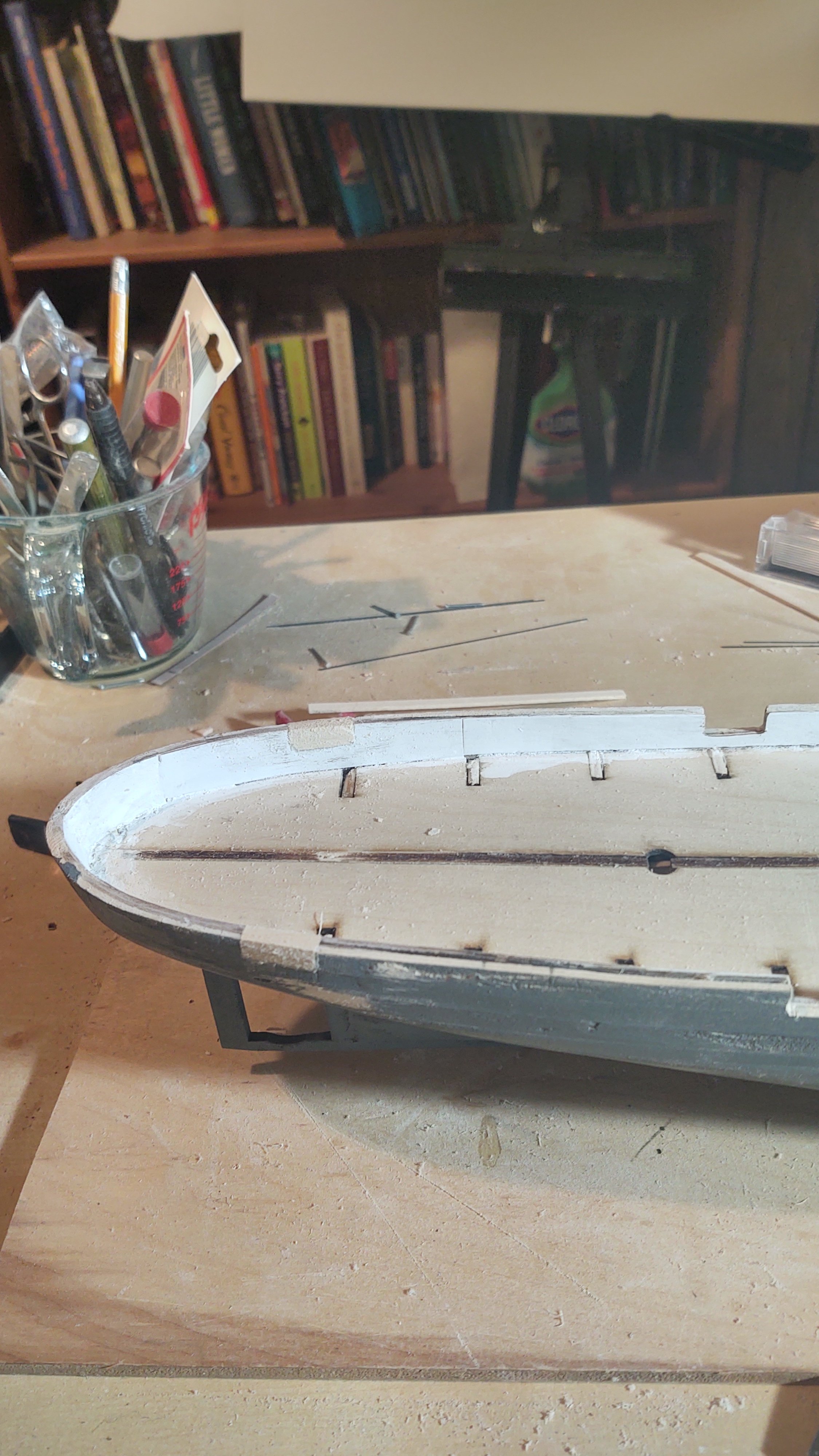
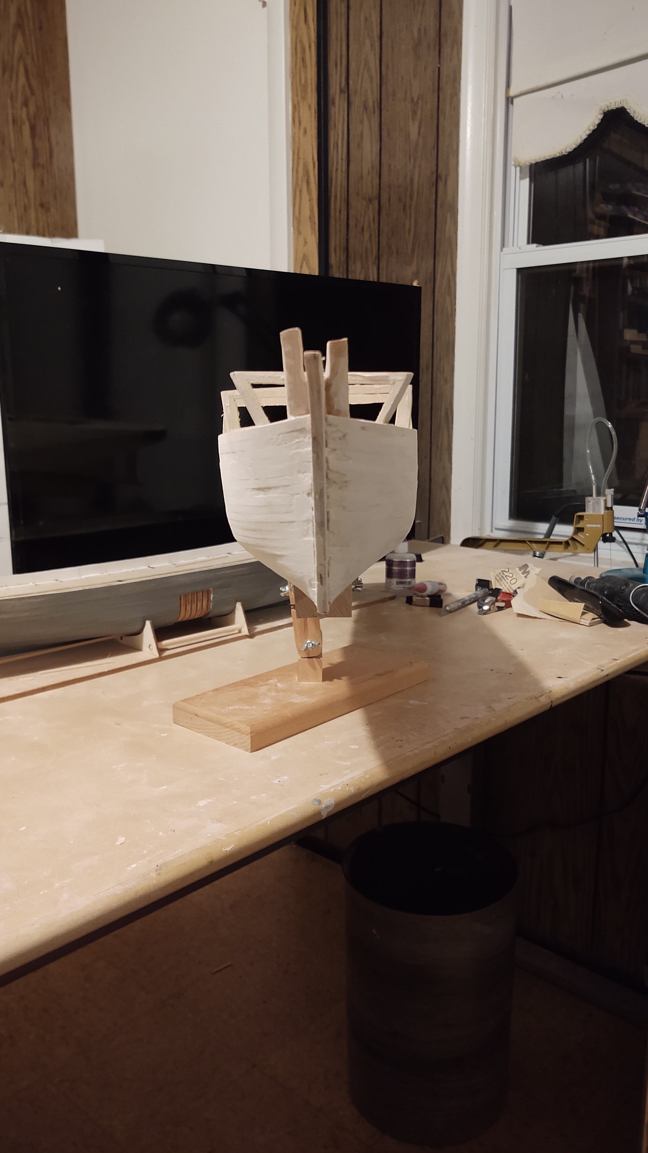
A brief update, as I haven't had as much time as I would like to work on the ship. However, some progress. First, I needed to continue whatever that timber represented by the 1/8 by 1/4 inch bass section is (it's not the waterway, which is 1 timber in, anyone has the right name please let me know) around the stern. To do that I cut a (sorta) semicircle (arc?) out of some 1/4 inch thick bass sheet that I had from another project, and notched it for the bulwark stanchions. As depicted in the plans, the stanchions appear to be closer around the stem - not too surprising since they maintain the shape of the bulwarks there. Here is a picture: That was then installed on the stem, and the stem evened so that the curve of the above piece and the stem matched: And the first planks have been added to the ship: I put a couple of pieces of 1/8 thick bass in the forecastle (hidden behind the first strake to give me a reference point to align the strake, but I'm not doing anything special inside the forecastle because it was closed off on the real ship. No sense modeling things no one will ever see. Anyways, thanks for looking in! Regards, George
-
Thanks Rick and Per! I haven't had a ton of time to work on this lately, or look into MSW for that matter. However, the basic hull shape is pretty much done. I put in the lower part of the stem and the false keel, sanded, primed, and sanded, and I think it is ready for the next steps. I also painted the inner bulwarks white, I prefer to paint as I go rather than doing a lot of complicated masking, so we'll see how that goes. Here is what she looks like now: Anyway, next step is to cut out the gun and sally ports. I was looking for the best way to transfer the locations, and thought I would use the deck on the plans (and will) but I was slightly annoyed to see that the plans are slightly smaller than the actual deck piece. If you look at the photo below, I've aligned the stack, and as you move forward and aft, everything on the plans is closer to the center than the rastered markings. Bottom line is that I'm going to need to locate the cuts, correcting for the size difference, and be attuned to potential problems when I build out the hammock rail boxes. Reminding myself that this is an 'Admiral' level kit. Thanks for looking in! George

-
A very brief update. Visually doesn't look much different, but I've put in the inner bulwark, which is cut from 1/64 inch wood. I wound up kinda not following the directions. It's supposed to be made as 4 pieces; 2 that are about 20 inches long and 1 inch wide (bow to about 5 inches from the stern, and 2 that are about 2 by 8 inches. I wound up using the carrier sheet for the middle bulwark to cut the long pieces, and made the stern section from 4 smaller segments, which I found to be easier, and still made a perfectly fine looking inner bulwark. Some sanding, a little putty and we have the ship as below: The instructions say that the bulwarks shold be 7/16 inch tall until about 5 inches from the stem, where thy rise to about 1/2 inch. If you form the bulwarks using the templated materials it too tall at the stern and way too tall at the stem. I wound up cutting almost 1/8 of an inch off the stem and about 1/16 off the stern to make it the correct size. I dry fitted the upper bulwark for the forecastle, and it appears that the curve is slightly off. I am going to cut the upper bulwark piece off just past the foremost deck beam, and fit a similar sized piece of wood to cover the last 1/2 or so. This does mean though, that the precut forecastle deck will not be congruent with upper bulwark (it will be a bit too small at the bow. Depending on some imponderables at this point (for example, how much material gets removed for the opening for the boswprit) I will either buy a piece of scribed decking or just cut a piece to fill the gap from the carrier. I doubt it will be very visible, the question will be how much will it will annoy me. I have also dry fitted the stem pieces. I may put the stem and the external keel in place before it is nominally called for in the instructions. Otherwise, next steps are to sand, prime, and sand, and then to cut out the gun and sally ports, and to cut out the slots where the channels will be inserted when the main rail is put in place, and the main deck. As always, thanks for looking in and the encouragement. Regards, George

-
There is clearly a (small) market for Transatlantic ships. Indeed, my wife and I are going to do the QM2 crossing from Southampton to NYC just before Christmas this year as a 60th birthday bucket list thing. But, as you say, it's pretty niche, and we had no trouble finding cabins. I get it's winter (well, we depart on Dec 14, so technically fall), but a 7 day voyage with a sheltered balcony was under $1500 (US) per person. Not exactly cheap, but not bad for transportation, room, and board for a week, and it doesn't suggest that high demand is pushing up the price. Nor would I imagine going on a second crossing, so it's niche without a lot of repeats. The SS United States is pretty clearly past her sell by date. If an American (or other) firm wants to muscle into Cunard's market they might as well build a completely new ship. The population that is even aware of her existence is not increasing, and while her lines are pleasing, naval architecture has advanced in the last 73 years. And anyway, the hull of a ship is the cheapest part, there is no real savings to be had reusing it, and probably a major cost penalty to make modern equipment fit into spaces it wasn't designed for. Regards, George
-
How was it? My wife and I went on the Rotterdam for our honeymoon 34 years, and we've been thinking about staying in her if we are ever in the neighborhood.


.jpg.33235f3e3ac4999f4fd9a45a6ba90f70.jpg)


.png.d80c4b5f0c34fab9dcff4e85cb4629b7.png)