donrobinson
-
Posts
1,909 -
Joined
-
Last visited
Content Type
Profiles
Forums
Gallery
Events
Everything posted by donrobinson
-
If you apply the finish to the hull and the ends of the planks first you shouldn't have too many problems with bleeding. My thoughts are that unless you can show the actual pieces making up an individual frame, as in Danny's, I would go with paint. Just my thoughts you are the Captain!!
- 99 replies
-
- 2
-

-
- essex
- cross-section
- (and 1 more)
-
Wow! That is a beautiful model Dan, I wish I was in that league. Doug adding veneer is a good idea, but the ends of the planks would not match properly would they. I didn't mind the looks of the black paint.
- 99 replies
-
- 1
-
-
- essex
- cross-section
- (and 1 more)
-
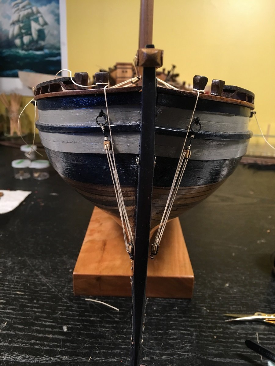
She is a thing of beauty EJ. rigging looks spot on. If you have the time could you take a front on picture? Incredible work!!
- 608 replies
-
- 1
-
-
- la couronne
- corel
- (and 1 more)
-
Using .5 x 6 mm strips line the inside of the opening keeping the front edge of the strips flush with the front edge of the bulkhead. Now install the 1'5 x 3 mm strips recessed 1.5 mm, to allow for the thickness of the door, as seen in P2, thus forming the door stop. The backside of the bulkhead can be trimmed or framed in with 1.5 mm stock, your choice. Next step is to apply the exterior planking, .5 x 6 mm. to the front of the bulkhead, this is installed so that it is flush with the edges of the door opening. The plans, which are accurate, are showing the progression of the build so what might seem like the end of a strip is actually a cross section. Where the red arrows are pointing there is no veneer, or filler exposed it is showing the exterior planking and it's thickness, giving you a 3d view of the layers involved in this particular part of the build.
- 204 replies
-
- 3
-
-
- trajta
- marisstella
- (and 1 more)
-
Good to see you back
-
I couldn't agree more about the boats being upside down, I suppose it would have been a big hassle loading and unloading. I would enjoy watching a tarp being made for it. I mean after all the canvas work with the hammocks how much trouble could a boat tarp be?
- 843 replies
-
- 4
-
-
- niagara
- model shipways
- (and 2 more)
-
The 6 x .5 mm does not need to be trimmed, you will need 3 mm for the 1.5 x 3 mm "door jamb" and then a 1.5 mm recess for the door, which will be 1.5 mm thick around the edges. There will be a 2 mm overhang on the inside of the bulkhead that can be left or trimmed if you wish. The walnut strips are as follows: 1st line is .5 thick x 6 mm wide strip - 54 pieces @ 6 cm long. The second line is ,5 thick x 6 mm wide walnut strip - 2 pieces @ 63 cm long these are for the wales, It is always best to use the short strips first saving the longer pieces for when required, such as the wales. The list is showing that if you want to cut all pieces ahead of time this would be the measurements you would use. If you don't want to cut all the pieces it would be then telling you that two pieces of 63 cm in length will be required at some point and time in the build so save at least two strips this long. Glad to have been of some help, I'll be watching. Mike I just edited this post and my last post to reflect proper measurements. I am starting to get the staircase syndrome
- 204 replies
-
- 2
-
-
- trajta
- marisstella
- (and 1 more)
-
Great start, your fairing of the bulkheads looks excellent. When I look at your signature there appears to be room for at least a couple of more ships in your "Current Builds" list
-
Hey Mike you are off to a great start. I'll try and answer your questions. The openings are lined with .5 mm material then using 1.5 x 5 mm wide material that you will cut to 3 mm wide line the opening again, this will create a 1.5 mm ledge or door casing in the opening to allow for the door to sit in. Did I explain this ok? The bottom numbers you have circled are: 4 mm - thickness of bulkhead, .5 mm -thickness of the exterior planking and the 6 mm is the width of the exterior planking. The reason the .5 mm planking seems to disappear is the exterior planking is added and hides that edge. If you look at it again where your line is pointing there is no exterior planking installed and just to the right of your line there is a exterior plank installed. Where you are asking about "three boards" your top line is pointing to the 1.5 x 3 mm door casing, the second line is pointing to the 1.5 mm ledge or space left for the door to fit in up against the door casing and the third line is pointing to the .5 mm edge of the exterior planking. What helps is to try and think in 3d, I know it is not as easy as it sounds but it works and you will catch on. I hope this all helps and I'll be on board waiting for more updates.
- 204 replies
-
- 5
-
-
- trajta
- marisstella
- (and 1 more)
-
Looking good Mike, I wouldn't worry about the hammocks too much. Once the shrouds are installed along with the rest of the rigging your eyes won't focus on the hammocks as much and they will blend in. The ship's boat sure catches your eye.
- 843 replies
-
- 4
-
-
- niagara
- model shipways
- (and 2 more)
-
I like how it is shaping up. Cross section is something I've wanted to try someday, please carry on.
- 99 replies
-
- 1
-
-
- essex
- cross-section
- (and 1 more)
-
The yellow looks terrific, several coats (10-12) of thinned down(50/50) paint will give you a great result. A real pain in the butt but it works. Looking very good and I'm waiting to see how you approach the gun ports. Nice work
-
Hello Michael, welcome to the build there is always lots of room and never the need to apologise for filling up the inbox with likes. I very much enjoy that. Drinking in the shipyard is allowed, however, until I find a way of controlling myself it is confined to spectators only. So you are good to go, fridge is in the back beside the recycle bin. Smoking is allowed in the two back rows and we ask that you turn off your cell phones while any power tools or sharp instruments are being used. All beverages are complimentary and self serve. Enjoy the voyage
- 653 replies
-
- 8
-
-
- trabakul
- marisstella
- (and 1 more)
-
I agree Jean-Pierre, same thing has happened to me.I now have my shipyard set up so that when the liquor cabinet door opens the shipyard door automatically closes and locks.
- 653 replies
-
- 9
-
-
- trabakul
- marisstella
- (and 1 more)
-
She looks marvellous EJ. Pour yourself one of your favourites, you have earned it!
- 608 replies
-
- 3
-
-
- la couronne
- corel
- (and 1 more)
-
Should be a interesting build. Looks like it is copper plated,are these supplied? Looks cool
- 99 replies
-
- 4
-
-
- essex
- cross-section
- (and 1 more)
-
Thanks Ian, I hope your holiday was a good one and I'll be watching for some updates
- 653 replies
-
- 5
-
-
- trabakul
- marisstella
- (and 1 more)
-
You sure have the upper hand on the rigging, great pictures and explanations.
-
Very nice Karl, you'll be planning your next build soon!
- 164 replies
-
- 1
-
-
- Model Shipways
- Finished
- (and 1 more)
-
For centuries people have been trying to turn lead into gold. You come along and bang!! Plastic into gold. Great work
- 140 replies
-
- 8
-
-
- jolly roger
- lindberg
- (and 1 more)
-
Popeye, in my post 506, the plan is showing the starboard side with blocks, this is why I thought both sides had them and didn't bother to look any further. Blocks are above the water line Mike, I like the looks too even though it is not right
- 653 replies
-
- 5
-
-
- trabakul
- marisstella
- (and 1 more)
-
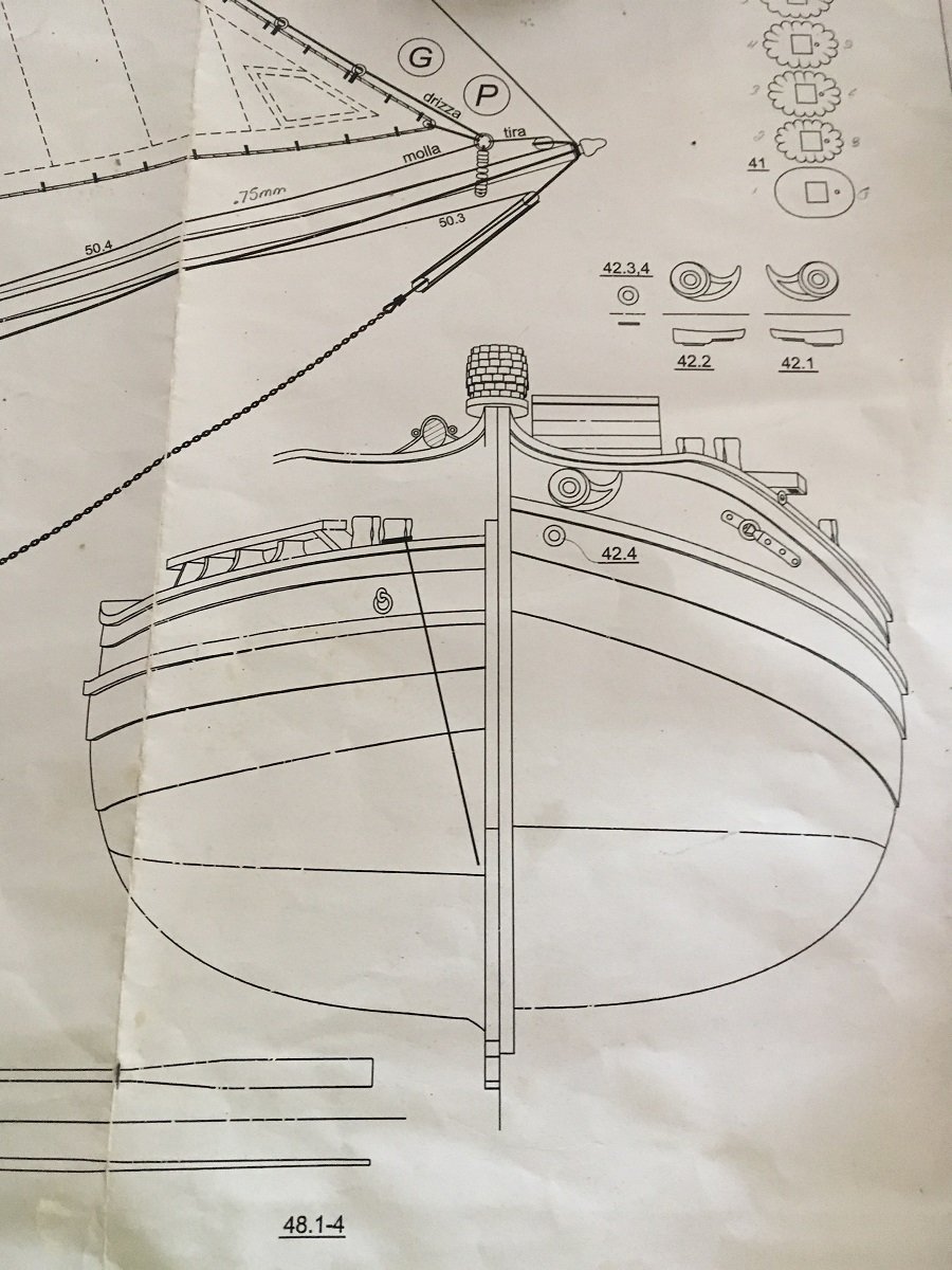
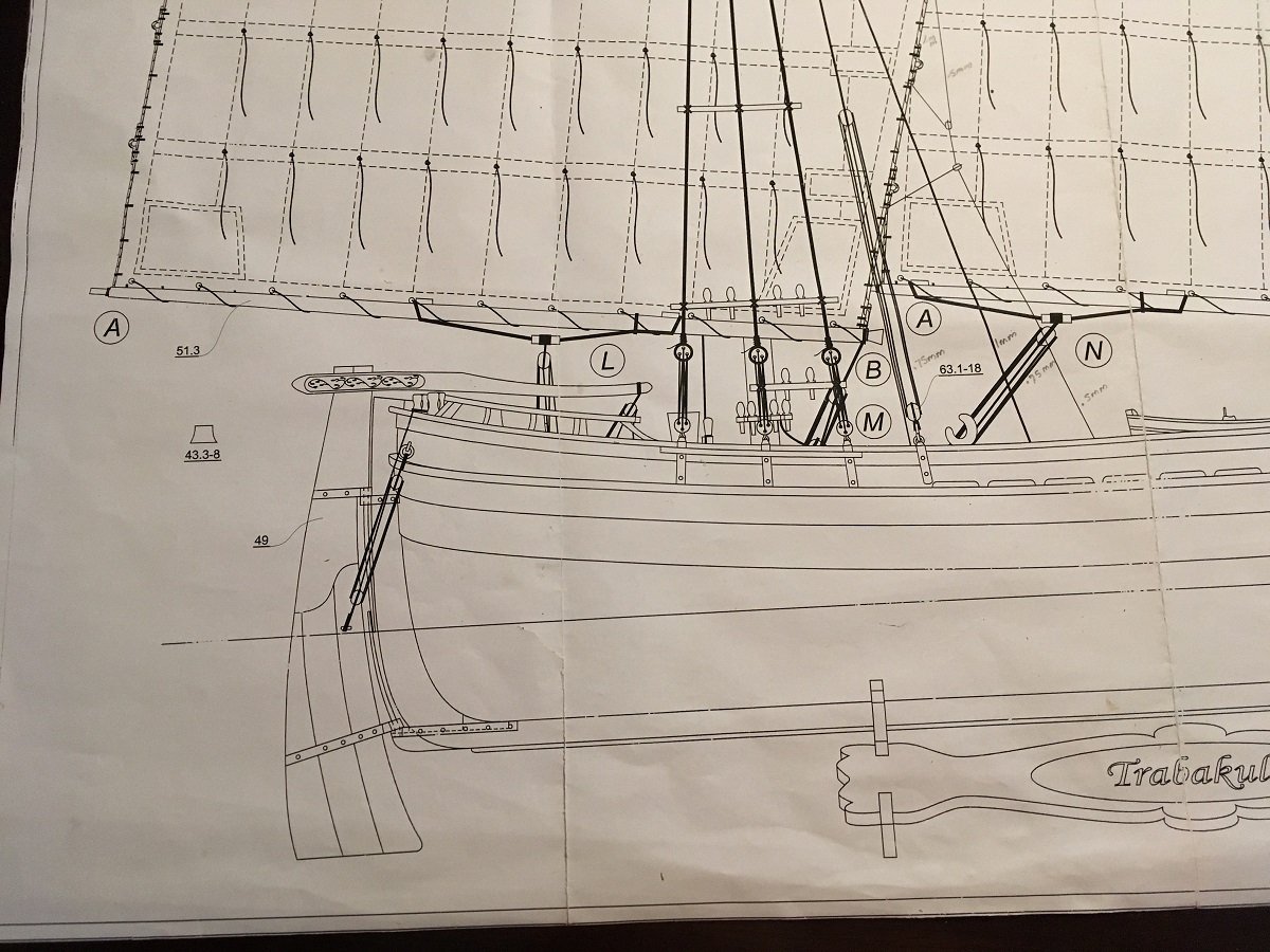
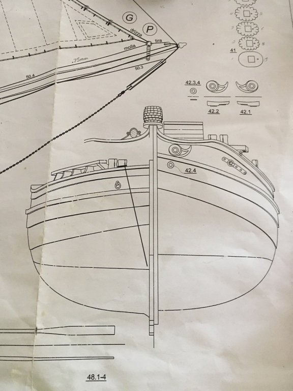
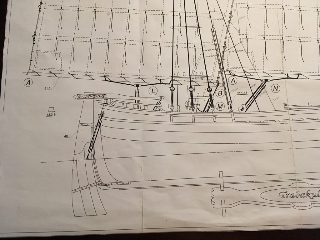
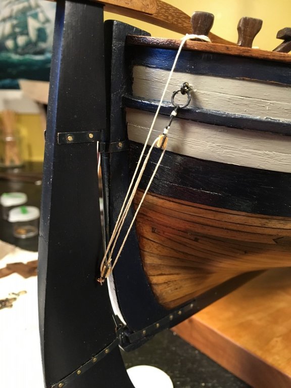
It was brought to my attention by a good friend of mine, Zoran, that I did the rigging on the rudder a little wrong. I went back to the plans and sure enough what I have done is not the same as what is shown As you can see the plans show only a rope on the port side tied to the rudder and on mine I have blocking on both sides. Now I know my way is wrong and not historically correct, however, I'm thinking in real life this rudder is almost 17 feet long, 4 feet at it's widest point and 6 inches thick. Given these dimensions this rudder would have weighed a ton (figure of speech) and raising it in shallow waters would have been some feat of strength. I'm thinking why not give this crew all the advantage possible and let them have a four block system Or should it be done the right way? Given the temperature today and this problem I am considering a trip to the refreshment fridge. Please help, or better yet come over for a cool one

- 653 replies
-
- 11
-
-
- trabakul
- marisstella
- (and 1 more)
-
Thanks Popeye for the compliment and joining in the log, always lots of room and never too late. These MarisStella kits have lots of cool features like the planked decks. One of the problems with the sails is that I don't put my models in cases ( the price of a case could easily buy another kit ) so I am concerned with the cleaning of the sails. I am still hashing this out. I suppose I could hire a sail cleaner once a year .
- 653 replies
-
- 3
-
-
- trabakul
- marisstella
- (and 1 more)
-
Thanks Rafine, Blighty, EJ, Mike and Dave for your comments. This is overwhelming. Thanks also for all the likes
- 653 replies
-
- 3
-
-
- trabakul
- marisstella
- (and 1 more)
-
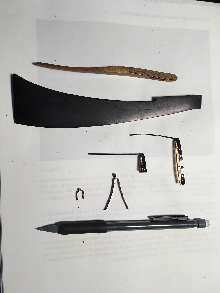
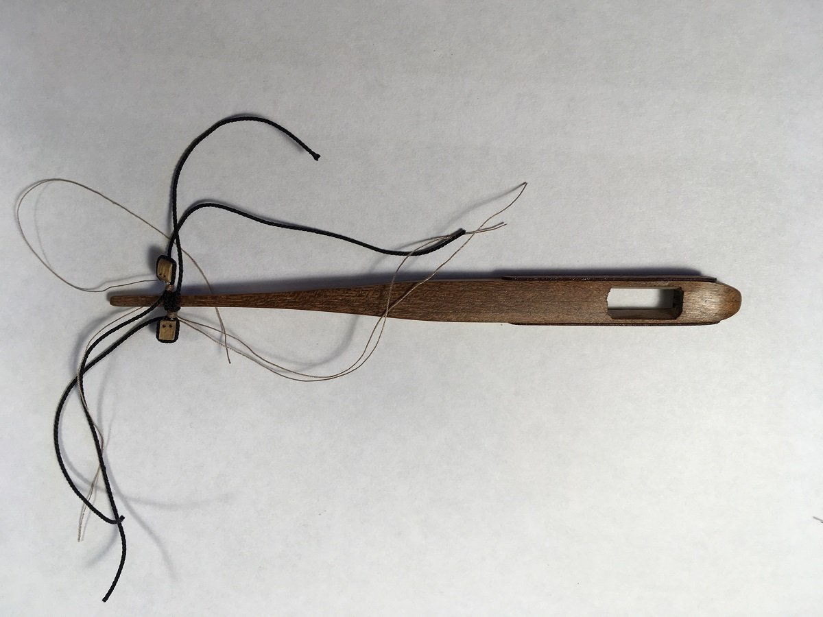
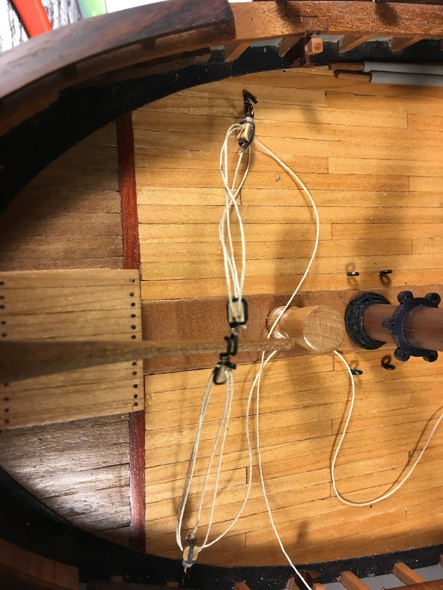
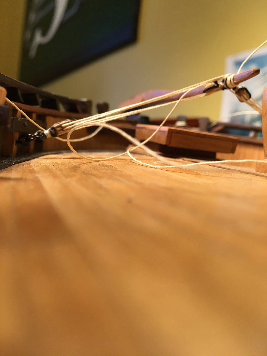
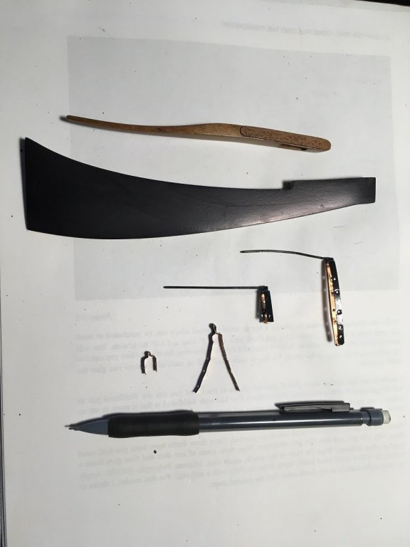
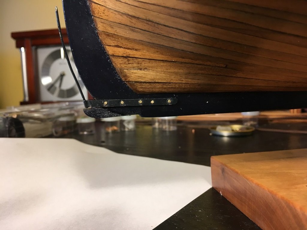
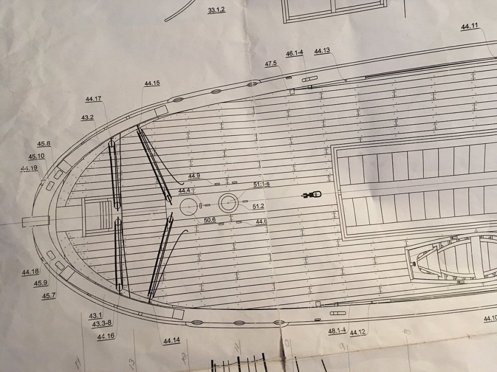
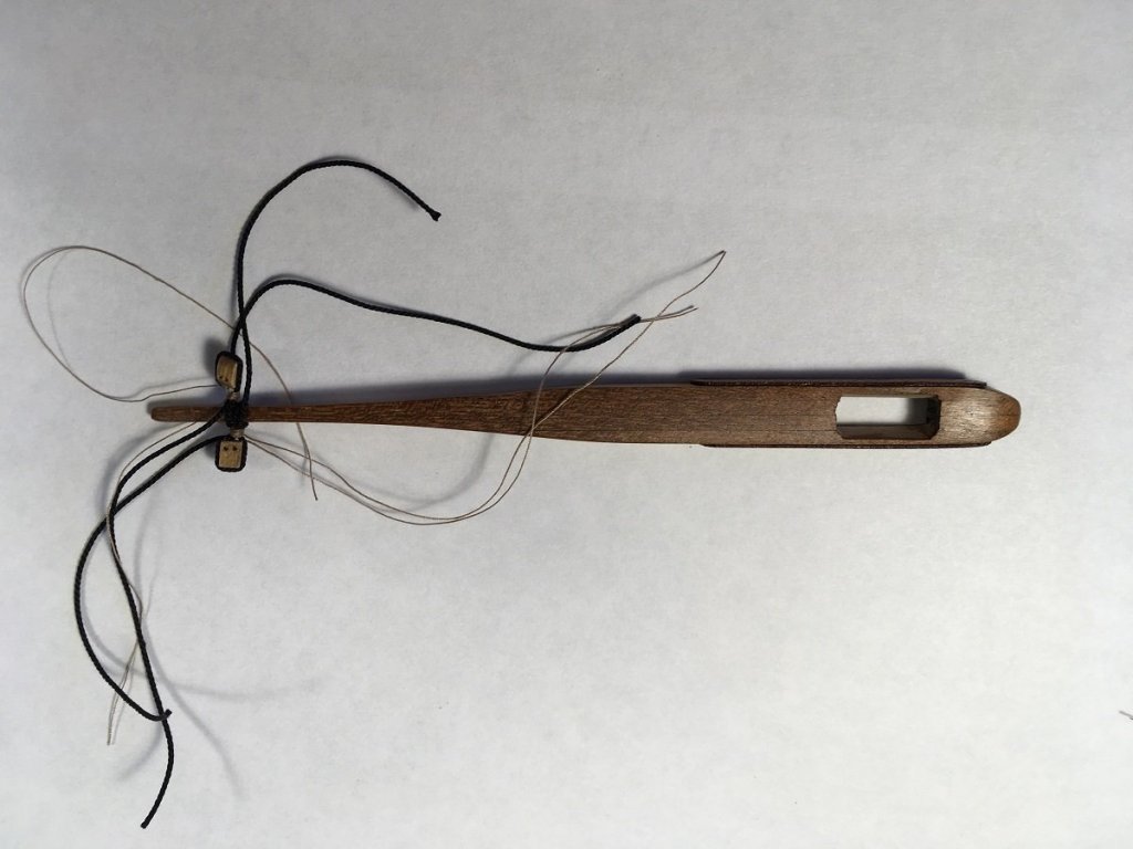
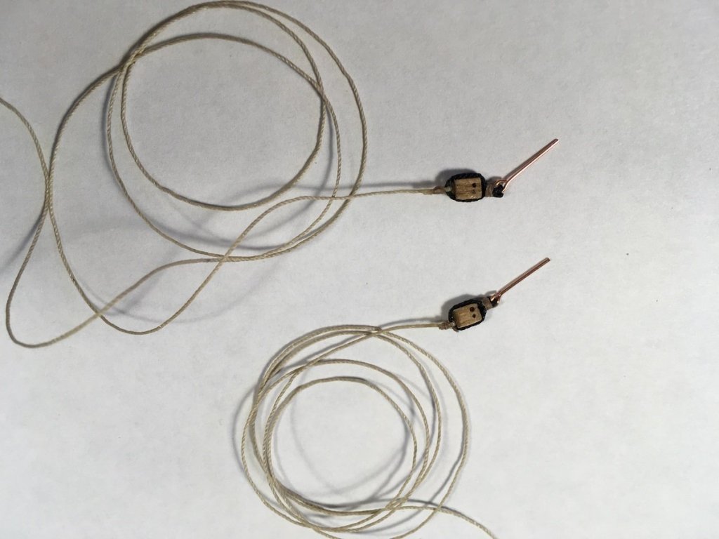
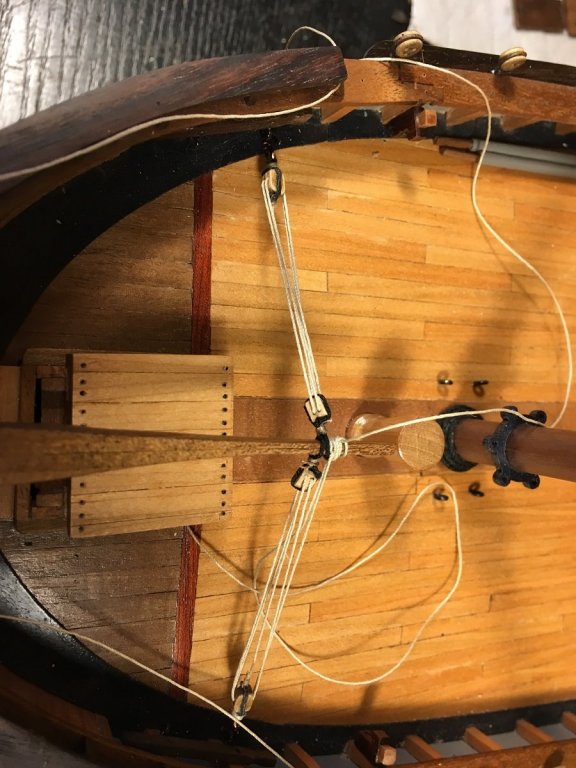
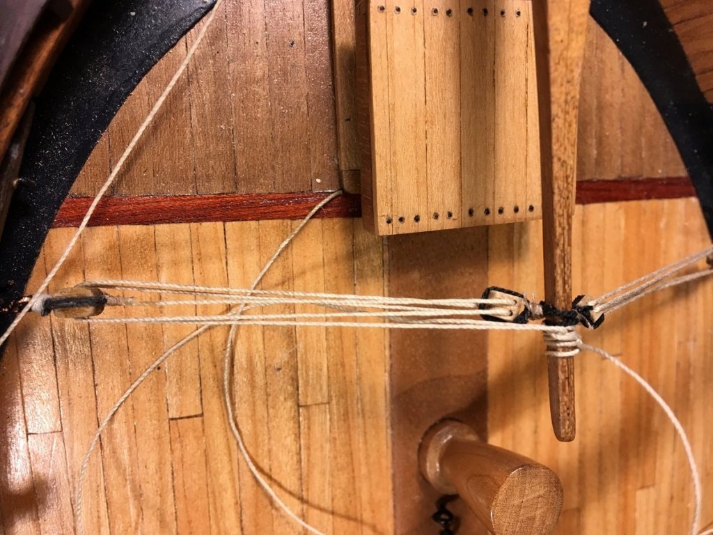
Today I gave myself a big list of things to do including dentist, grocery shopping, 5 acres of grass to cut then finish with completing and installing the rudder. If successful I promised myself a bbq steak and a trip to the liqueur cabinet( trying to follow EJ's footsteps) Well steak is still the fridge yet but there have been a couple of trips to the infamous cabinet, all jobs completed!!!!! I realise there is a little overkill with pictures on this post, I feel there is never too many pictures when it comes to the rigging aspect of a build so please bear with me. This what the task was for today. Top picture showing the rudder and the next picture showing the rigging for the tiller. Pieces for the rudder, straps made from 3 mm copper strip Still needs painting, this is showing the bottom bracket and bar mounted on hull the top bracket and bar is then mounted on the rudder. Receiving bracket is then mounted on hull at top and on rudder at the bottom. A much easier process, I love it!! The tiller being rigged with 4 mm double blocks. Seizing is done using Gutermann thread readily available, wide assortment of colours and measures approximately .18 mm Blocks and rope for rudder, 4mm blocks .5 mm rope and eyebolts all kit supplied, used approx 50 mm of rope for each. It is the same set up for the tiller with the exception of the eyebolt, a hook is used instead. Showing rigging of the tiller, the use of hooks helps so much. Here I am showing running the rope through the blocks before attaching the hook to eyebolt in bulwark. I will adjust that block after I'm done here. The plans do not show any sort of belaying point so I am assuming coils of rope will be needed below the tiller later on. I have read the rope was wrapped around the tiller first to allow the helmsman to make adjustments?????? This is what the ship's cat might see. You all Take Care, Thanks for stopping in.


- 653 replies
-
- 16
-
-
- trabakul
- marisstella
- (and 1 more)