jml1083
-
Posts
195 -
Joined
-
Last visited
Content Type
Profiles
Forums
Gallery
Events
Everything posted by jml1083
-
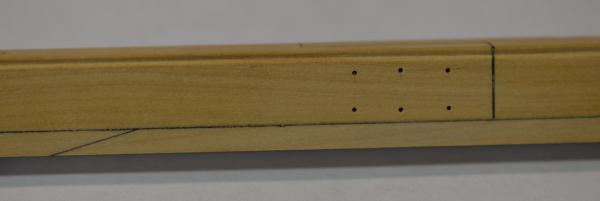
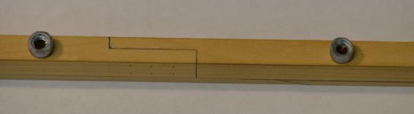
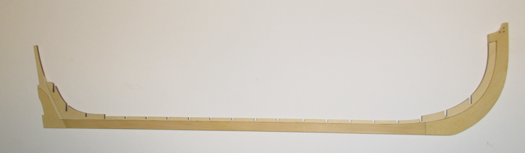
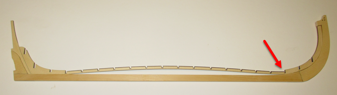
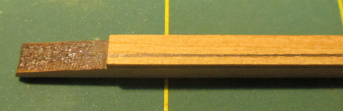
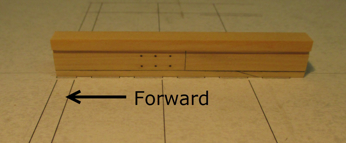
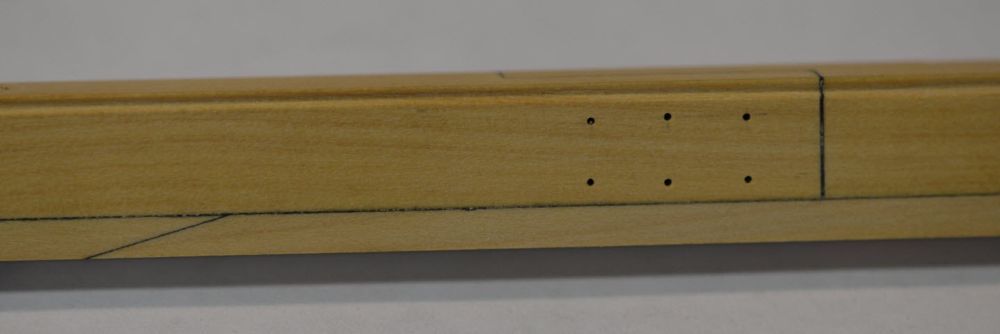
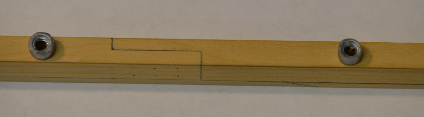
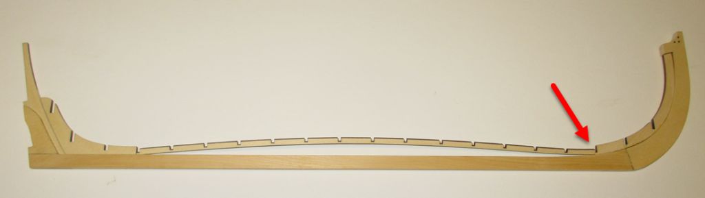
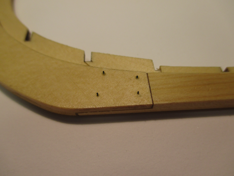
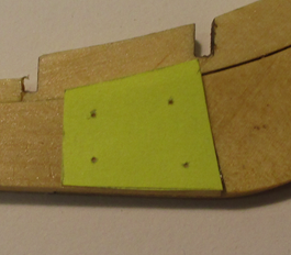
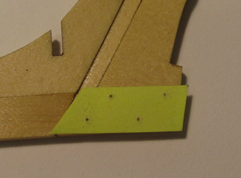
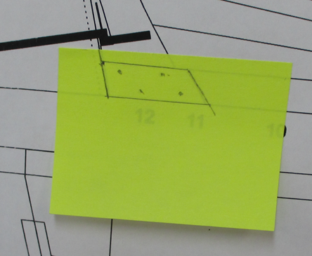
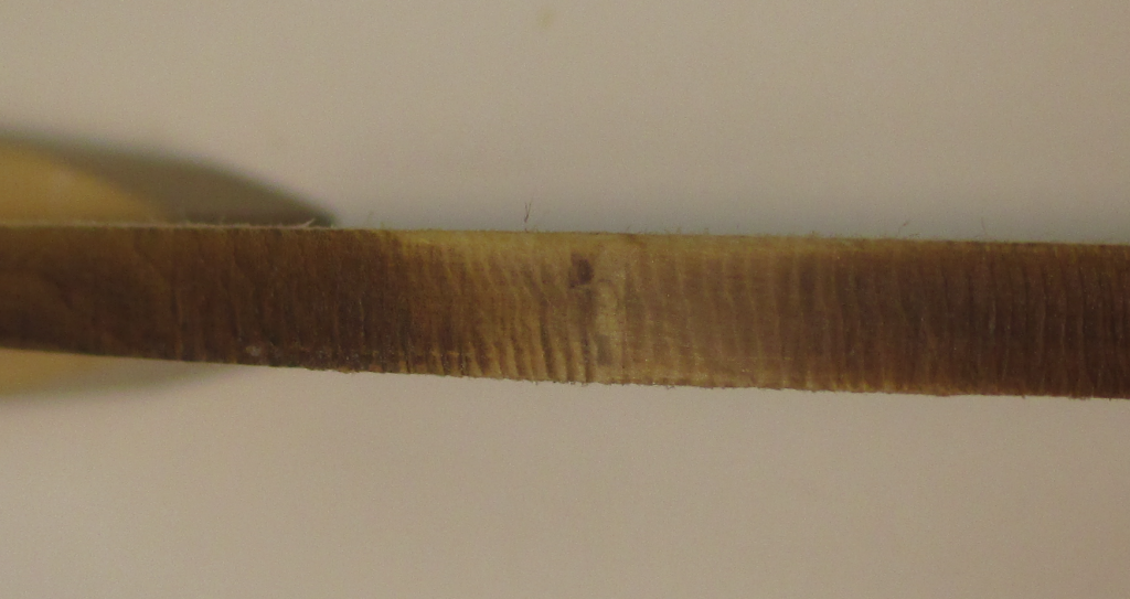
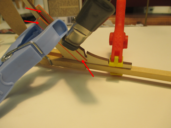
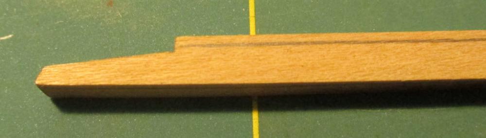
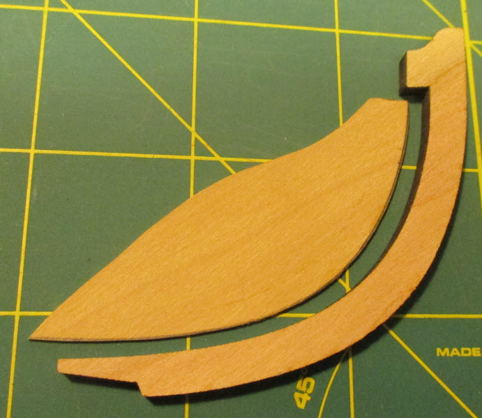
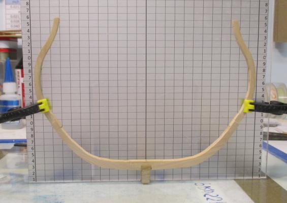
 Minor progress today but progress is progress. Once the glue dried on the work I did the other day it was time to install the thin keel piece with all the notches for the frames. As with the previous work I did not remove the char from the bottom of this piece and used yellow wood glue so I'd have time to position the piece exactly where I wanted it. In the first photo you can see that this piece is very slightly over sized. This is a good thing so that you can adjust for any slight variances in your model. The fix is to carefully sand off a tiny amount of wood from the FORWARD part of this piece (red arrow shows where to sand). If you look at the piece you'll see that the forward end is blunt whereas the back end has a small step cut into it. If you sand the back you will create a smaller recess for the frame to fit in. After very little sanding the piece fit snugly without creating a bow (see below). To get accurate positions for the bolts in the keel I used a small Post-It note. I stuck it to the drawing, traced the outline of where it goes, marked each of the bolt holes, then cut out the template. With the templates stuck to the keel I drilled the holes using a #74 drill bit. The #74 slipped right into the hole even with glue on it. After I finished the first side I flipped the keel over and positioned the templates then drilled the holes using the holes made in the templates from the other side. Once the glue is dry I'll use a razor blade to cut off the fishing line that is protruding above the surface of the wood. A lite sanding and then a second coat of Wipe-On-Poly to finish this part of the keel. On to frames next.
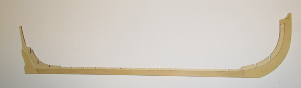
-
Very nice work Ken. You and I are at the exact same place. I'll bring my model to the next meeting.
-
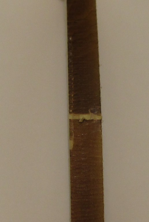
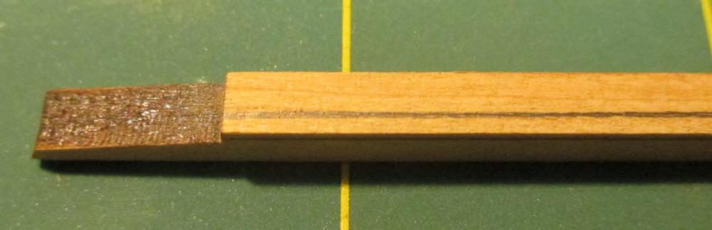
After a very long absence I'm back at the ship modeling workbench. I've retired since my last posts on my Bluenose (which is still waiting in the wings) and retirement presents its own happy challenges that kept me out of the shop. I'm now up to 4 grandchildren and thrilled that they keep me really busy. The oldest is 9 and the youngest is 8 months old. Competition trapshooting keeps me very busy and during the nice weather I'd rather be on a trap field that holed up in my windowless shop. During the spring and summer months I travel throughout the northeast US for competitions and as a consequence I'm no where near my shop. I have really missed ship modeling but the longer I was away from it the harder it seemed to get back into it. I'm still a member of the Ship Model Society of NJ so I keep in touch with modeling that way but it's not the same as sitting at the bench making something. My Bluenose is years behind schedule and the more I concentrated on trying to get that moving the more discouraged I became. Chuck is a very good friend of mine and he saw what I was struggling with and suggested I ease myself back into it via a group build of the Medway Longboat. That was the best idea I've heard in a long time so here I am. Mike (Stuntflyer) is also a friend and member of SMSNJ and I've been watching his progress closely both in person and by following his build log here on MSW. We were both at Chuck's house today and they convinced me that in addition to building the longboat, keeping a build log will keep me connected and, I know from past experience, motivated. So, here goes. Work started today and I'm taking photos as I go and will post the ones I think most beneficial to others. If you have questions about how I did something please don't hesitate to ask. To assemble the keel I'm using yellow Titebond wood glue. This will give me time to adjust pieces and things "just right" before the glue sets. I've not had problems with gluing on laser char in the past so I don't sand the char away, in most cases. This first photo shows how a piece looks when it comes out of the billet. The cream colored line is where the little tab was that connected the piece to the billet . The next photo shows the extent to which I sand the piece to remove what's left of the tab. As you can see I don't take off very much char or wood. It is only enough that when I run my finger over it I can't feel any sort of bump where the tab was. Once I reach this point I stop sanding. This third photo is how I assembled the 4 pieces of the stern. The wood is very slightly oversized in thickness so I sanded it until it was very close to .0938" (3/8"). If I didn't do this there would have been less that 1/32" rabbet. I used two pieces of 1/32" scrap, one on either side so that when I clamped it all together the gray clamp holds everything nicely centered. The blue clamp keeps the vertical pieces in contact while the glue dries and the red clamp does the same thing for the horizontal glue joints. The red arrows and thin red lines show the 1/32" alignment pieces. I used a lap joint to join the keel pieces but my photos of that process came out horribly which I didn't realize until after it was all assembled. I used a #11 scalpel blade to make a stop cut and then whittled away at it until the joints were only a few thousandths of an inch over size then used sanding sticks to clean it all up. It was easier than I thought it would be. My first inclination was to pull out the mill for this but I realized set up time would probably be longer than the process I used so I didn't go that route. Tomorrow I'll finish the keel and move on to making frames. It feels good to finally be building again and writing this log.
-
Hi Roman. Many thanks for supporting our forum. I wish you much success!
-
The Keel The first element I tackled is the keel which is made up of 8 laser cut pieces. Before removing them from the billets I sanded off the char that was left on the backside of the billet from the laser. There really wasn't a lot but it's easier to remove it from the faces before you remove it from the billet. Once that was done I liberated the pieces from the billets. The keel has rabbets, which are nothing more than bevels, on the top side of the keel. The keel itself is 5/32" thick and the rabbets need to be 1/32" x 1/32". I cut a piece of 1/32" scrap and used it to trace a line on the sides and top of the keel which I then pared down using a #11 scalpel blade. On the curved stem I did the same thing using a scrap piece that had the correct curve traced from the stem. On the sides I used a compass with a very sharp pencil. This photo shows the side of the keel with the rabbet line drawn. The top of the keel would look the same. This step is done after the various keel sections are glued together. This is a shot of the curved 1/32" piece I used to trace the rabbet line on the stem. Just slide the piece into position and trace your line. Flip the stem over and trace the line on the other side.
-
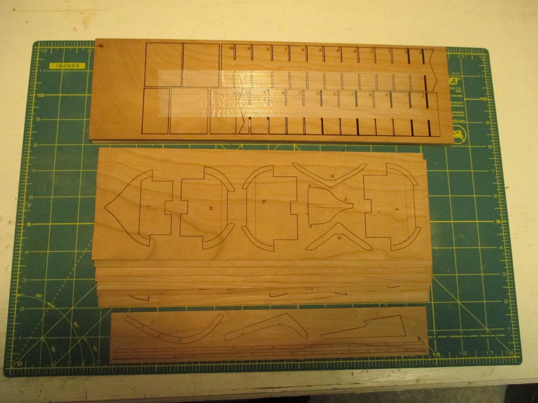
This is a photo of the kit right out of the box. The cherry is beautiful and this will be a striking model when it is completed. The top piece is the build board, also made out of cherry. It comes in two pieces with slots where each of the frames will be positioned. This type construction eliminates all of the added bracing people used to try and keep frames square when they build the Pinnace. This type build board keeps the frames square and level making construction that much easier. The location of each frame is labeled on the build board to reduce the chance of placing a frame in the wrong location.The large blocks to the left are feet that will be glued onto the build board to raise it off the workbench so the tops of the frames have clearance. In the middle are the sheets that contain the floors and futtocks. In another post I'll go into detail about how these are assembled. At the bottom of the photo are some of the thicker elements, also made of cherry and also laser cut.

-
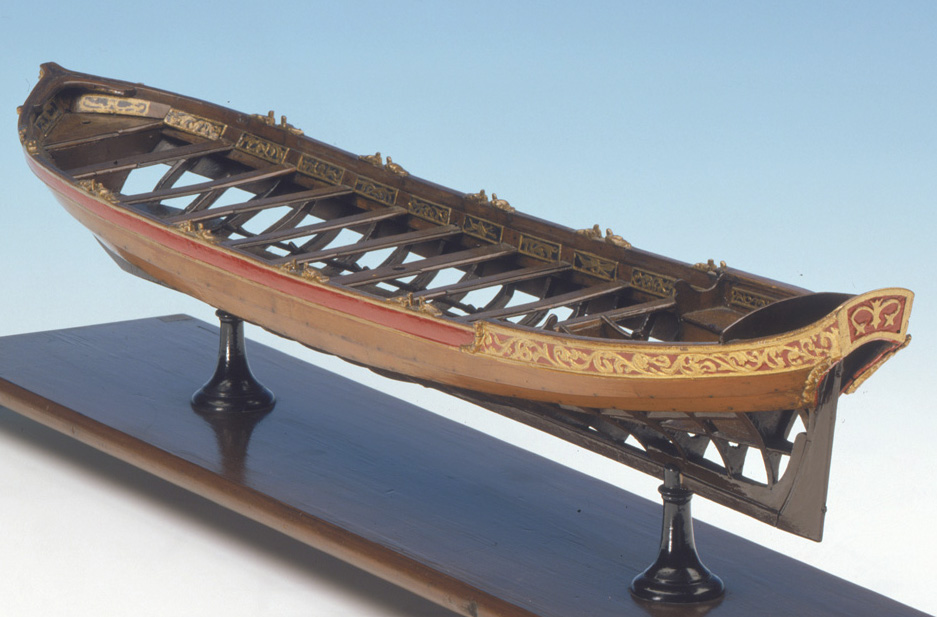
This is Syren Ship Model's soon to be released kit. It is plank on frame and will be built admiralty style with frames showing. Chuck has come up with an ingenious way of constructing frames with floors and futtocks that uses laser cut parts. The kit uses cherry for most of the parts but some embellishments will be in boxwood. This is a photo of a similar model from the National Maritime Museum
-
Toni, so sorry to hear about Sadie. I know how hard it is to make that decision. You have my most sincere sympathy.
-
Echo by jml1083 - 1:48 - Cross-Section
jml1083 replied to jml1083's topic in - Build logs for subjects built 1751 - 1800
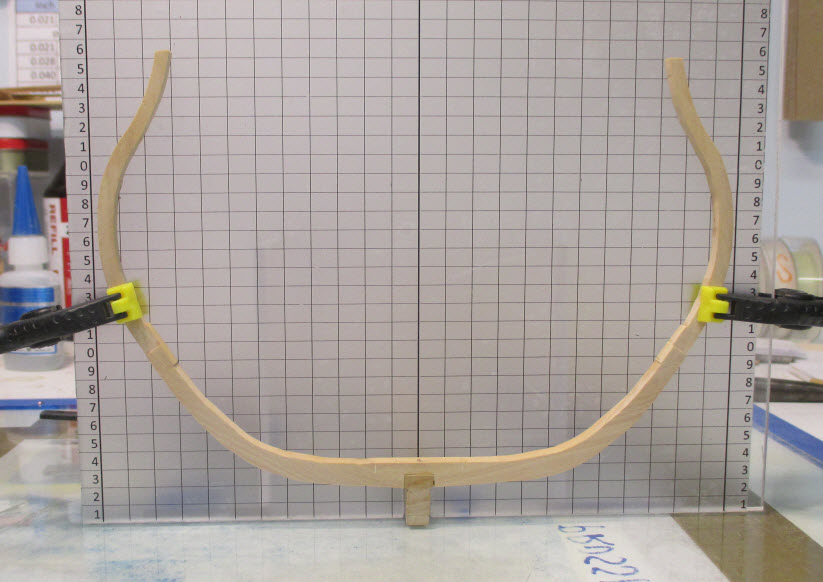
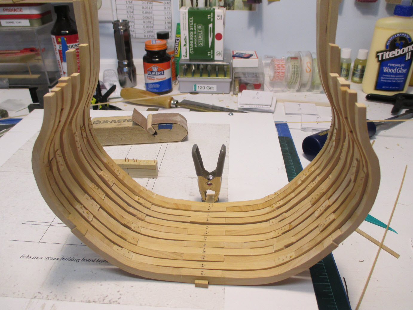
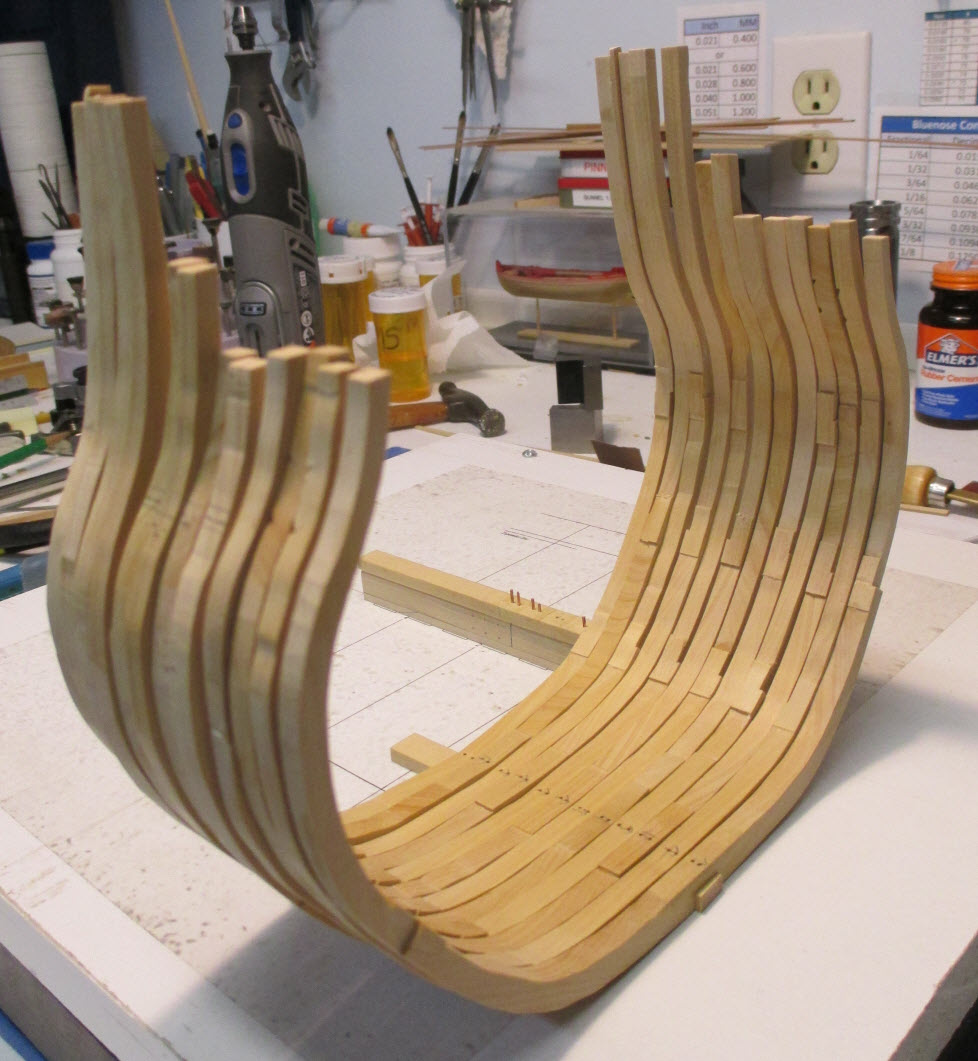
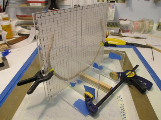
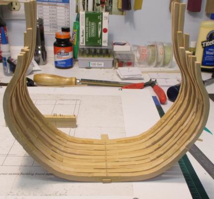
Today I started to raise frames. I made a jig out of 1/8" plexiglass to help make this process as accurate as possible. The profile of the keel structure is cut into the bottom of the face piece. The grid you see on the face was made in MS-Excel to no particular scale. I printed the grid out on self-stick Mylar. This first photo is from the front and shows the Deadflat0 frame in place. The second photo is the back of the jig from an 45° angle to show how everything lines up. The blue tape is just to make the pieces stand out a bit. After applying the Mylar grid to the front and cutting the base so the keel is exactly dead center I built the back supports. These are nothing more than 2 bases with an upright glued to the center. For these it is important to make sure everything meets at exactly 90°. The front of the uprights is perfectly flush with the front of the bases. Once the glue has had time to really set I went about attaching the back supports to the back of the face piece. To do this I slide both supports into the keel which I used to set the proper gap. With both support pieces in place I ran a line of glue along the base where the supports meet the face piece. After a couple of seconds I made sure the face piece was in contact with the front edge of each support and ran a line of glue down these joints. When I'm raising a frame I use a small bar clamp to gently squeeze the keel assembly with the bases of the support pieces. This keeps the whole thing from moving as I raise the frame. The third photo is another view of the back of the jig, this time looking straight on. Because everything is square to everything else this makes a handy way to raise frames and check their alignment. The scale of the grid doesn't matter, the lines are just used to check symmetry. The jig is used on a piece of glass to make sure the base I'm working on is dead flat. Once the glue has dried on one frame the jig can be slid back to make room for the next frame. Up next is raising the other 11 frames then I'll install the gun port sills, sweep sills and scuppers.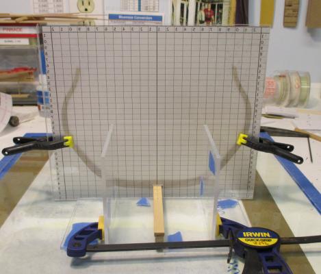
-
Echo by jml1083 - 1:48 - Cross-Section
jml1083 replied to jml1083's topic in - Build logs for subjects built 1751 - 1800
Hi Druxey, I tried bamboo but had no luck. I was using bamboo skewers sold in packs of 100 for the food service industry. The wood is very dry and hard as I tried to split the bamboo down the middle my knife would take a zig to the outside and that was the end of that. Even soaking the wood for awhile did no good. I wonder if there is a better source of bamboo that I could use that is easier to split. -
Echo by jml1083 - 1:48 - Cross-Section
jml1083 replied to jml1083's topic in - Build logs for subjects built 1751 - 1800
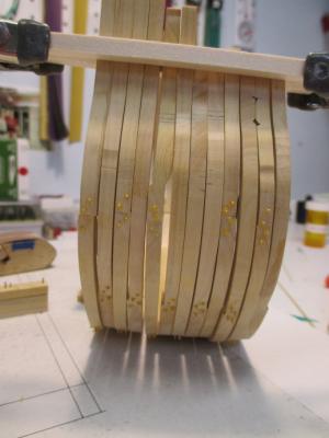
Quick update on treenails. I debated using actual treenails or doing what Maury did, which looks just as good. In the end I went with actual treenails for a couple reasons. The primary reason was for strength. The second reason was I wanted to see how painful this was with just 144 before I commit to doing the hull this way. Treenails were made using a Byrnes draw plate which puts a smile on my face every time I use it. Such a simple tool but poorly made it can be a horror. Jim's draw plate is a precision tool which is a joy to use. I started with 1/32" x 1/32" (.79mm x .79mm) boxwood and drew it down to .021" (.53mm) which equates to a treenail that is 1". I believe this is a little over sized but I had trouble pulling the boxwood any finer than that. One of the guys in my club (Roy) gave me a great tip for using the draw plate which I will pass on here. He suggested that after I pull the piece through the draw plate and I reverse the wood and pull it through again. When you get to the smaller diameters this really makes life a lot easier. I found once I got under about .28" I would pull the wood through each hole 4 or more times. The more times you do it the faster it goes and it makes it a lot easier to get the next smaller diameter going. I drilled the holes using a #74 carbide drill bit in a drill press. I found that using yellow wood glue on the treenails gave me a snug fit. The jury is still out on doing the hull with actual treenails. I actually enjoy drilling the holes and inserting them, it's just that pulling them takes so much time. I spent over an hour pulling enough boxwood to make the 144 treenails needed for the chocks. Up next I will double check the locations of the remaining gun port sills, scuppers, etc and then cut the grooves. Once that is done I'll raise the frames and get to work with fairing the hull.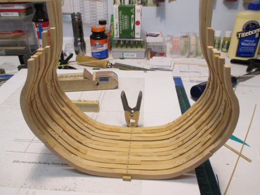
-
Echo by jml1083 - 1:48 - Cross-Section
jml1083 replied to jml1083's topic in - Build logs for subjects built 1751 - 1800
That's great news Greg! At our last SMS-NJ group build meeting this was one of the topics of discussion. We had Jason from Crown Timberyard on Skype and he was asking us what types of wood we want to use. I brought up the cross section that you use as your avitar as a really nice example of using a variety of woods to finish the Echo. Towards the end of the PowerPoint presentation from the Echo Cross Section workshop you and David did there are some really nice color photos. I'm pretty sure we are going to go with the same woods you used. We want to get back to Jason in the not too distant future so he can put together a quote on what this will cost. If you can send me your recommendations on what woods to use I'll bring it up to the group. -
Echo by jml1083 - 1:48 - Cross-Section
jml1083 replied to jml1083's topic in - Build logs for subjects built 1751 - 1800
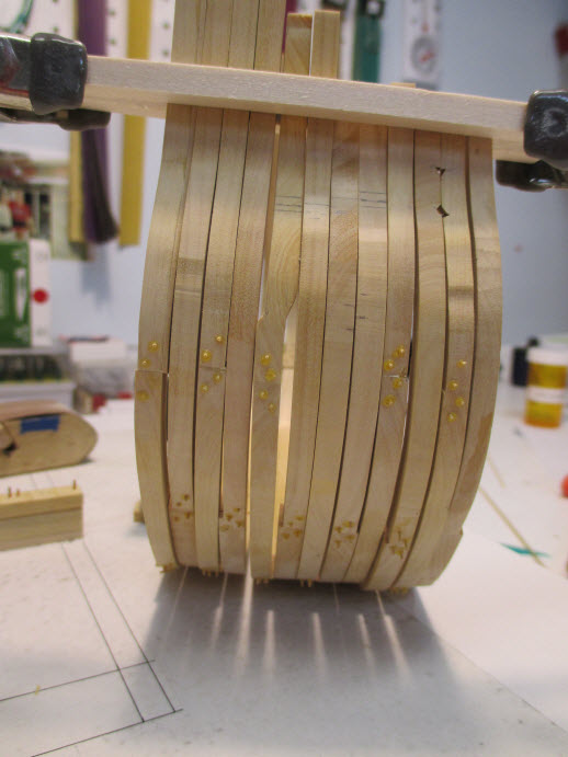
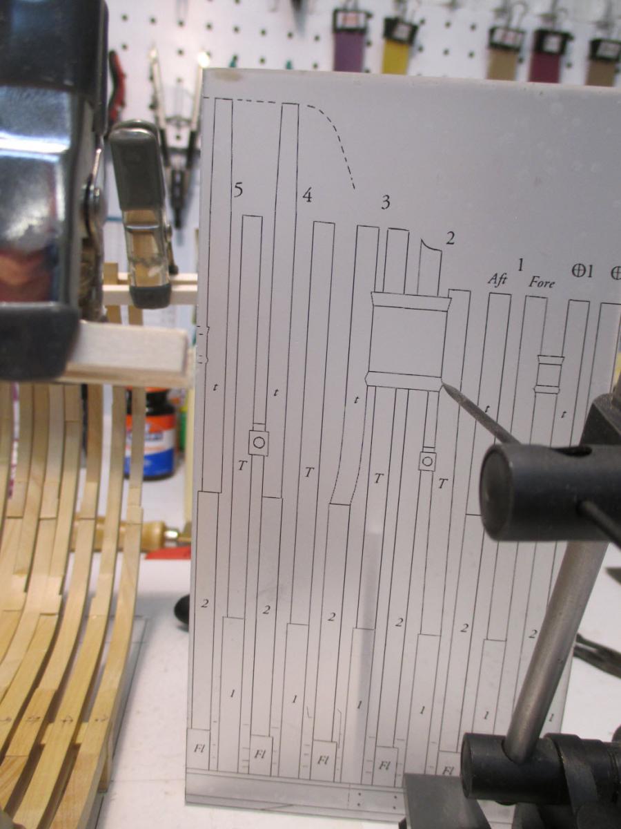
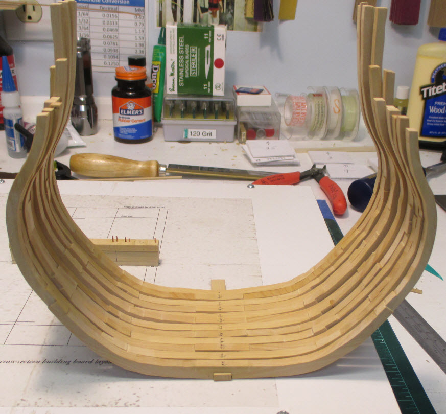
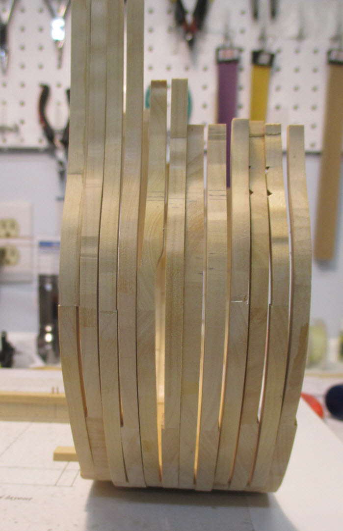
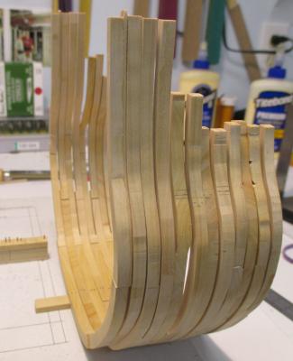
Hi Greg, yep if you have to refer to those directions for each frame you would be in a world of hurt. My hope is that when people read them they will understand the simplicity of the process (despite the number of words needed to describe it) and then they will only have to refer to it if they run into a snag. As you know I write software test plans for a living and so I spend many happy hours documenting processes with hundreds if not thousands of steps. The process contained in the PDF was written while drinking a cup of coffee As promised here are some photos of my progress so far. The first photo is of the surface gauge I use to take points off the Disposition of Frames which I mounted on a plexiglass backing. This plexi backing keeps everything in proper relation height wise. After a while I realized that it would be easier if I replaced the hardened steel pin with a sharp pencil which I have now done. This next photo is of all the frames sitting on top of a scrap of wood the same width as the keel. The frames are all bunched up against one another so they don't fall over. Some of them are a very tight but others have a bit of wiggle room in them consequentially some of the tops of the frames look a bit out of kilter. These next 2 shots show a side view of the frames. An observant reader will notice that the frames are not stood up in the proper order. You can see where I have started to create the notches for the scupper opening as well as the gun port sills. You can be sure I'll have them all in the correct order when I glue them into place. The last photo is a different angle and shows how well everything fits together. You'll notice marks on each frame directly above the keel. These are little arrows pointing towards the bow. They are there to keep me from gluing a frame into place backwards. I learn from my mistakes. Next up is drilling holes for the treenails. That will keep me busy for a little while.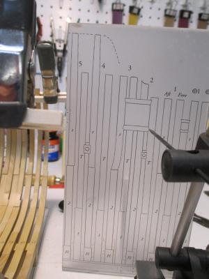


-
Echo by jml1083 - 1:48 - Cross-Section
jml1083 replied to jml1083's topic in - Build logs for subjects built 1751 - 1800
It has been a long while since I posted so it's time for an update. I have finished all 12 frames and this time I'm happy with the way they came out. I'll post some photos of them later when I get back down in the shop and take them. I spent a lot of time trying to come up with a process that would allow me to make accurate frames in the shortest time possible while keeping mistakes to a minimum. At some point after I retire I'd like to tackle a fully framed model but to do that I need a better way to make frames than my first attempt at the ECHO. Attached to this post is a PDF file that explains in, what some might call excruciating, detail my method. What I found is that when I tried to make one frame at a time I wasted a lot of time doing set ups on the mill that I had done for the previous frame. The way around this is to do all like operations at the same time. I marked up every template page before cutting and gluing any of them to stock. When all the templates were glued to stock I headed to the scroll saw where I cut all the pieces at once. I used small plastic bags with a label to identify what the bag held. With all the pieces cut I went to the Byrnes disk sander where I sanded the mating surfaces of each piece (this is explained in the PDF). With this critical step done I went back to the scroll saw and got rid of a lot of the stock that would otherwise have to be milled. This is done AFTER the sanding step so that when I sanded the mating surfaces I'd have as much of a line to sand to as possible. Next up is the mill. Here I organized the pieces to optimize each milling step. This is how I went about that. Arrange all pieces along the left side of the mill according to the thickness of the wood. Except for Frame 3 which has some complex geometery this means floors would be milled first, then pieces that get progressively thinner as you get higher up on the hull. When you hold a floor in your hand and look at it you realize 3 milling operations are needed on it. One to mill the left area where a chock will go, the center recess where the floor will sit on the keel and the right side of the floor where the other chock will go. To save having to do repeated set ups I milled cut out for the left chock first. I then moved the piece in the mill vise and milled the center recess for the keel. I then removed the floor from the mill vise and set it on the right side of the mill. Next I milled the next floor but this time I milled the recess for the keel first since the cutter is already in position to do this. Then I moved the XY table to cut the area for the left chock. Then the piece is removed from the mill and put on next to the first floor that is on the bench to the right of the mill. The next floor had the left chock recess milled, then the center then removed and put to the right of the mill. This continues until all the floors have the keel recess and left chock area milled. Next comes futtocks that have both a left and right chock area that needs to be milled. I did all the left areas and when that was done I took the piece out of the mill vise and put it with the floors. After the futtocks with a left and right chock are milled you will have 2 sets of top timbers, one set for the starboard side and one set for the port side. Mill all the futtocks with a left chock area. You'll notice as you work though the pieces to be milled you are optimizing each setup. When you have milled the last of the top timbers with a left chock the mill vise is set for thin pieces. Move to the items you have been lining up on the right side of the mill. Starting with the top timbers work your way through the items ending up with the floors that have had the left chock area and keel recess milled. With all the milling out of the way I used tape to attach specific pieces of framing to a paper template. In my head I think of them as foundation pieces because they are the starting point for the frame. Once all the foundation pieces have been taped to the template I join the pieces that attach to them. These are butt joins and very weak. By doing all the edge gluing first you give the first joint time to cure while you are doing the others. I usually allow a couple of hours to really let the glue cure. With all the frames assembled I mark out each chock that is needed by sliding the chock stock under the window in the template and using a very sharp 4H pencil use the outline formed by the futtocks to trace the outline of the chock. Each chock is labeled as to the frame and location. With all the chocks drawn on stock I use the scroll saw to cut them all out. After cutting them all out I use the 5" disk sander to gradually sand to the lines and test fitting them until they are perfect. One I have the right fit I glue the chock into place and move on to the next chock on that frame. It's just that easy If you have read this far you are a trooper. As promised, here is the Process for making frames with chocks.PDF. I found that once I figured out the process I could move very quickly. I had iTunes queued to my favorite playlist and got into a groove. Good luck and have fun. -
Echo by dvm27 - Cross Section
jml1083 replied to dvm27's topic in - Build logs for subjects built 1751 - 1800
Beautiful work Greg and a belated Happy Birthday! -
Hi Mike, It was great meeting you last night at the Ship Model Society of New Jersey meeting. Your work on the Mayflower is meticulous. Using boxwood in place of basswood where the wood will be seen really adds to the overall impression of it being a quality build. You have a real eye for detail. I look forward to seeing you at future meetings and watching your Mayflower evolve.
-
Hi Maury, I'll be watching your Cheerful log closely. I just bought the Cheerful plans and when I finish the projects I'm in the middle of I'll get started on it.
-
Hi Jay, Fabulous work as always! I can't begin to count the number of things I've learned from your log. Thanks for such detailed posts.
- 732 replies
-
- 3
-

-
- constitution
- model shipways
- (and 1 more)
-
Echo by Maury S - FINISHED - Cross-Section
jml1083 replied to Maury S's topic in - Build logs for subjects built 1751 - 1800
Very impressive work Maury! I refer to your build log often. -
Echo by jml1083 - 1:48 - Cross-Section
jml1083 replied to jml1083's topic in - Build logs for subjects built 1751 - 1800
Thanks Greg! I'll pass your advice on to the gang. -
Echo by jml1083 - 1:48 - Cross-Section
jml1083 replied to jml1083's topic in - Build logs for subjects built 1751 - 1800
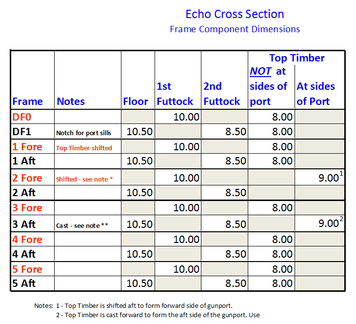
Tomorrow the Ship Model Society of NJ will have their monthly Echo Cross Section group build meeting. With the holidays and repeated snow storms, which means more time outdoors and less time in the shop, progress has been slow on all fronts. One of the things people seem to be struggling with is what dimension wood is used for each frame component. To simplify matters for everyone I've created this matrix. Greg or David can chime in if anything is incorrect. Notice that the column for 3rd futtocks is hidden. This is because although there is a dimension given (8.25") on all the frame drawings none of the components are listed as being a 3rd Futtock. Several members have told me they will run short on 8.25" wood but I don't see how that is possible since none is used, correct? I'll check back in the morning before the meeting and update the matrix if need be and then print out copies for everyone to take back to their shops. Thanks for any insights.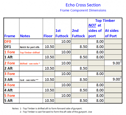
-
WOW Toni, this is very, very impressive!
-
Echo by jml1083 - 1:48 - Cross-Section
jml1083 replied to jml1083's topic in - Build logs for subjects built 1751 - 1800
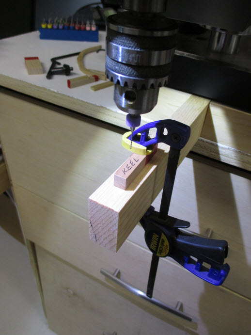
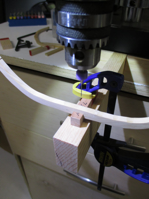
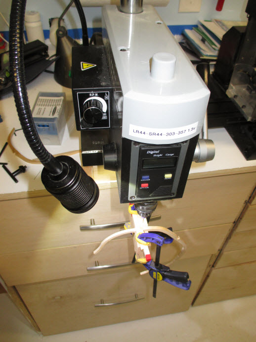
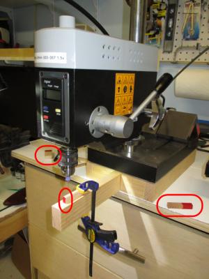
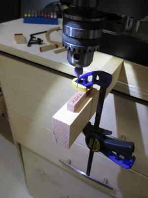
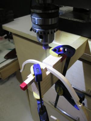
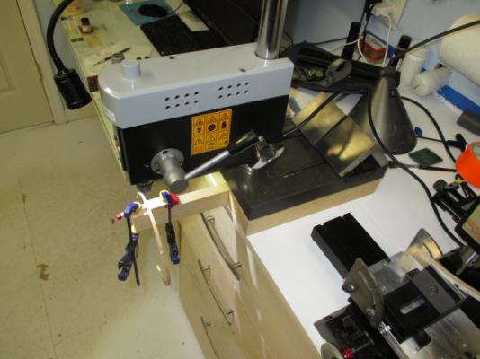
Jig for drilling treenail holes At the last SMS-NJ Echo Cross Section workshop the topic of treenails came up. Specifically, how to drill the holes without breaking the drill bits. I use solid carbide drill bits from Drill Bits Unlimited. Carbide bits are very sharp but they are also extremely brittle and the slightest sideways pressure will snap them. I always use a drill press with these bits. A number of people asked how I manage to drill out frames in a drill press without something getting in the way. My answer is that I built a little jig that my drill press sits on that has an arm sticking out beyond the edge of the workbench and that's what holds my frames when I am drilling. This first photo is of the jig itself. The back section is the exact same size as the footprint of my MicroMark drill press. The next photo shows my drill press sitting on the jig. With the MircoMark drill press I can rotate the head 360 degrees and in this case it is rotated 180 degrees. For safety sake I use two heavy steel alignment squares as counterweights on the drill press platform. The things circled in red are bits of wood that are shaped in such a way that they make alignment easier. In my shop I always paint little things like this red so at the end of the day they don't get swept into the trash. In this photo I have a piece clamped to the arm. This piece is a half round piece of dowel. It's used so that curved pieces can sit on it and touch nothing else. In the next photo I have a piece of wood that is the exact width of the keel. I clamp this to the arm when I am drilling the holes through cross chocks and 1st futtocks. Here is a floor sitting on the keel sized piece ready for drilling. The next photo shows how I drill through the futtocks and chocks. I brace the back with a block of wood, position the piece to be drilled, and then slide another small piece of wood up against the piece to be drilled. With everything clamped in place the assembly is rock steady and I don't need to worry that it will rock while being drilled and snap the drill bit. I find one of the easiest things to do that adds to accuracy is having good lighting. This next photo shows my light setup. I use small but very bright LED lights that attach to my tools using strong rare earth magnets. They have a goose neck so I can reposition the light as needed. Here is the link to the light on Lee Valley's website. The last photo shows another view of a frame ready to be drilled. You can see how the arm extends beyond the base of the drill press and how the frame is positioned on the arm and is held in alignment by 2 pieces of wood clamped to the arm. You can also see how well lit the field is and you can also see my heavy counterweights. It is important to make sure you have adequate weight on the back of the drill press to make sure when you pull the handle down you don't pull the entire drill press into your lap. I have two frames complete (Deadflat 0 and 1) and I hope to get two more done this weekend. Time will tell. In the meantime I hope this explanation of how I drill holes for treenails will be helpful.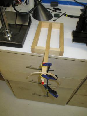


-
Echo by jml1083 - 1:48 - Cross-Section
jml1083 replied to jml1083's topic in - Build logs for subjects built 1751 - 1800
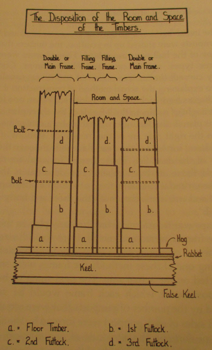
Thanks for the Likes and comments. I think I'm off to a good start. While doing research on another project I ran across something that clarified the terminology of the frames for me. The following graphic is from Peter Goodwin's The Construction and Fitting of the English Man of War 1650 -1850. When looking at the frame layout for dead flat 0 I couldn't remember if the timbers that abut the chock are first or second futtocks. This matters of course because it determines the thickness of the wood. Sorry for the parallax, the graphic is a photo I took of the drawing, not a scan. I hesitate to scan an exact copy of someone's work, the photo has enough distortion as to be unusable as a drawing but still illustrates the point I wanted to make. Maybe Greg or David, as published authors, can weigh in on this. With frames that are joined with a chock on top of the rising wood the pieces of wood joined by the chock are FIRST futtocks. On top of first futtocks are THIRD futtocks. On top of the third futtock is the TOPTIMBER. Where there is a floor timber across the rising wood the pieces of wood that connect to the floor are SECOND futtocks. On top of second futtock would be a FORTH futtock, if the ship was large enough, OR in the case of the Echo, the TOPTIMBER. Hopefully this will be helpful for others who are just starting out on their Echo. As this is a group build for the Ship Model Society of NJ and only 2 people have started to raise frames I know there are 6 to 8 others who will reach this point in the near future.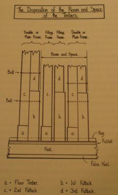
-
Echo by jml1083 - 1:48 - Cross-Section
jml1083 replied to jml1083's topic in - Build logs for subjects built 1751 - 1800
My keel is complete. For my first pass I used black tissue paper which looked really great but I over sanded it and the keel ended up with a very nice taper to it. Too bad that wasn't the look I was going for. The problem was the glue was harder than the wood and so sanding to get rid of the glue squeeze out took a real toll on the wood. For the he second pass I went back to using artist charcoal rubbed on the mating surfaces. This worked out well so I went with it. The 7/8" bolt holes were drilled using a drill press with a #76 drill bit. I used copper beading wire that I roughed up with a green scratch pad to get down to clean copper. With the copper clean I dipped the end of the wire into CA glue and quickly inserted it into the hole. I used good side cutters to cut the wire off nearly flush with the surface. Once the glue was dry I carefully filed the wire almost flush. I used a stabilized liver of sulfur gel to blacken the ends of the bolts. I used the gel full strength and applied an almost microscopic drop onto the bold head using a hypodermic needle. Once it was blacked to my satisfaction I very carefully removed the liver of sulfur residue with a small amount of water on the end of a 30/0 paint brush. All in all I'm happy with the way the bolts came out. Liver of Sulfur gel cost about $10 for a 2oz. bottle but it has a very long shelf life and a little bit goes a long way. The rabbet was cut using a 3mm dockyard V gouge. It is very hard to control such a small tool when cutting a straight line so I make the handle larger by sliding a long piece of copper tubing over the handle and then crimping it in place. Voila, a long handled micro gouge! With the rabbet cut pretty close to final size I used several different jeweler's files to get it just right. Greg suggested I leave a tiny bit of meat on the keel for when I start framing so I can get a perfect fit between the keel, frames and garboard strake. With the false keel and keel assembled I very carefully marked out where the mounting bolts were going to go and I drilled all the way through the false keel and keel. I'm going to use 6-32 bolts and nuts to mount the keel assembly to the building board and later to a display board. The nuts for the bolts were too big to be covered by the rising wood so I filed them down to they are just a bit wider than the bolts. I also filed them down height wise so that they grab a little less than 3 threads. After carefully measuring how long the bolts needed to be I test fit the keel to the building board. Once I was satisfied that all was in good order I used 5 minute epoxy to attach the now rounded nuts to the top of the keel. Here is a picture of the keel with the nuts attached. Next I used my mill to cut the recesses needed in the rising wood to hide the nuts. These recesses were cut a bit oversize to allow me a little wiggle room when gluing the rising wood to the keel which was the next step. Here is what the keel assembly looks like on the building board. The building board is nothing more than a piece of 5/8" / 15.8mm white shelf material. I printed the cross section on self-adhesive mylar stencil film from Treeline. Mylar is dimensionally stable and also fairly sturdy which is why I used it for the build board. At about $1 per sheet I won't be using it for frames. This is where I'm at today. With a four day weekend ahead I hope to make progress on the frames.