jml1083
-
Posts
195 -
Joined
-
Last visited
Content Type
Profiles
Forums
Gallery
Events
Everything posted by jml1083
-

Echo by jml1083 - cross-section
jml1083 replied to jml1083's topic in - Build logs for subjects built 1751 - 1800
Hi Hamilton, Like you I thought the Echo cross section would be a great way to get into scratch building and POF at the same time. I know several people that attended the last session in the fall and they all said it was very worthwhile. I am a member of the Ship Model Society of NJ and at our last meeting one of the guys brought in his Echo cross section so I could see what the workshop covers. I was very impressed, nothing is stylized, the frames are build just as they were on the original. Over the weekend I gave Greg my order for their Echo cross section kit. It is small enough so that even in my little shop I can work on it and the Bluenose at the same time. Living just outside NYC Baltimore is only about a 3.5 hour drive. If I remember correctly you live in the Vancouver area so Baltimore would be a pretty long haul. Maybe they will have the next session out west somewhere. I'll be posting photos of my cross section as I go. -
Hi Hamilton, Your Glad Tidings is coming along very well. I remember your work was always very detailed and you work FAST! Glad to see you posting here. I'll be following your build.
-
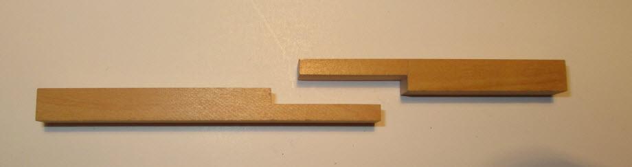
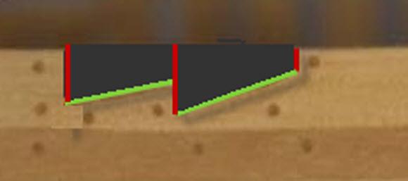
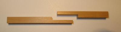
Hi Erik Here is one possible way. The first thing I would cut are the red lines which seem to be vertical. I would cut them on my table saw. The angle of the green line can be found by placing a large shim under one end so that the green line becomes horizontal. Hot glue the shim in place so that it doesn’t move but is easily removed once you are done. Once you have found the horizontal raise the table saw blade so it cuts to the deepest part of the joint. Make repeated passes over the table saw blade moving the piece slightly to the side until the dark gray area is removed. Do the same thing with the adjacent dark gray area on the same piece. Once all of the dark gray area has been removed I would use files and sanding sticks to make sure the bottom of all cuts are flat and square to the sides of the wood. Then I would lay this finished piece on its mating piece and trace a very fine line following the outline of what was the red and green lines. This will give you an exact template of what needs to be removed. Then just remove the stock in the same way. I would use an auxiliary fence to support the wood as you are running it over the blade. Needless to say I'd keep my fingers out of the way. I am sure there are other ways to do this as well. I hope this helps.
-
Echo by jml1083 - cross-section
jml1083 replied to jml1083's topic in - Build logs for subjects built 1751 - 1800
Thanks Mario, I got the idea for the higher backing when I saw the size of the frames in your log I figured it would give me a little more stability and I could draw a centerline on it. The frames look very fragile and I thought maybe a temporary piece running across the tops of the frames would make them a little more sturdy and at the same time I could mark the centerline on that cross piece and align it with the centerline on the backer. Just thinking ahead which I'm not sure is a good idea when I don't know what I'm doing in the first place. I will bring my camera to the workshop and take some photos. Initially my intention was to take the workshop just so I would know what goes into this type of build but the more I read about it and see it in practice (again your log is a very helpful) the more I want to build the full cross section. Enjoy the day. -
Echo by davec - FINISHED - cross-section
jml1083 replied to davec's topic in - Build logs for subjects built 1751 - 1800
Very nice work Dave. Looking forward to meeting you in Baltimore. Regards, -
Mario, Your work is magnificent! Thanks for posting such detailed photos and comments about how your perform each step. I will be following your progress closely. Regards,
-
Echo by jml1083 - cross-section
jml1083 replied to jml1083's topic in - Build logs for subjects built 1751 - 1800
Thanks everybody, I am really looking forward to this workshop. Having only done plank on bulkhead kits previously this workshop really raise the bar for me. The final photos before the workshop are of the framing jig. framinggig1 framinggig2 It seems like a very long time since I posted anything on my Bluenose so I'm going to get to work on the main cabin in the hopes I will have something post-worthy soon.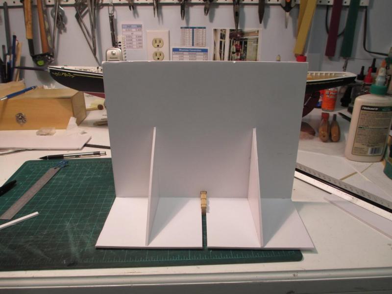

-
Echo by jml1083 - cross-section
jml1083 replied to jml1083's topic in - Build logs for subjects built 1751 - 1800
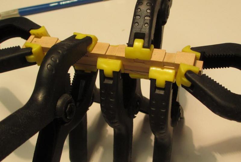
Toni, thanks for the tips on other helpful items to bring. Since I'm driving down I don't have to worry about the TSA and having sharp things in my bag. Jamie, thanks. I looked at this workshop last fall but couldn't swing it work wise. It wasn't looking too good for this session either but about a month ago things opened up at work and I was able to book one of the last seats in this session. Well, I'm done with the keel and it's on to the framing jig. The macro lens on the camera really shows every fiber, luckily it looks better in person. Lots of clamps on such a tiny piece. 3 hold the 1.5" spacer, 2 hold the rising wood centered on the keep and 2 to hold the rising wood down on the keel. finishedkeel1 Finished keel from the side. The blackening keep flaking off the wire so what I ended up doing was putting a tiny drop of CA glue (used a needle) on the end of the wire which left a very slight bump to simulate the head of the bolt. Also using a needle I put a tiny drop of flat black paint on top of the CA glue. finishedkeel4 End view. finishedkeel5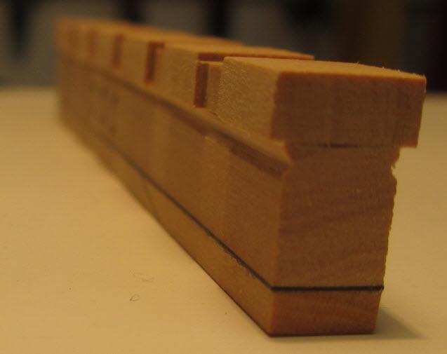
-
Echo by jml1083 - cross-section
jml1083 replied to jml1083's topic in - Build logs for subjects built 1751 - 1800
Hi Bob, thanks! I'm looking forward to meeting everyone and raising that first frame. I cut the rabbet using a 3mm micro V-gouge. rabbet1 rabbet2 Next step is to glue it all together.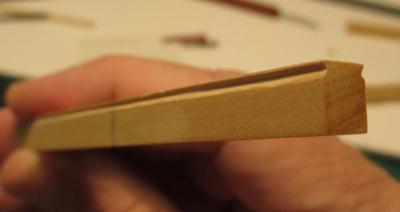
-
Hi Michael, there is a good reason for all the dories, it took that many before I found 2 that I felt good enough to be on top of the stack and visible to one and all. I actually started getting into it after awhile. The one displayed off the starboard side was an afterthought when I found I had 3 that passed inspection. Jay, you're too late! Just this past weekend I was looking at the rigging plan and my eye kept wandering back to the ship and it occurred to me that I'm going to have a difficult time drilling all the holes in the deck around those stacks which are not only nailed to the deck, they are epoxied as well. Live and learn. You say I'm being watched like it's a bad thing to have folks who do much better work than I keeping an eye on me It's one of the big benefits to MSW !!
-
Echo by Maury S - FINISHED - Cross-Section
jml1083 replied to Maury S's topic in - Build logs for subjects built 1751 - 1800
Maury, Thanks for posting the photos, they are a big help. I like your two custom vices, very ingenious. -
Echo by oneslim - cross-section
jml1083 replied to oneslim's topic in - Build logs for subjects built 1751 - 1800
Looking good Bob! What did you use to simulate the 6 bolts? I live up at the other end of the state (Bloomingdale) and like you feel fortunate to live not too far away. This should be a great workshop. I'll see you on the 8th. -
Homemade tools collection
jml1083 replied to greg-kam's topic in Modeling tools and Workshop Equipment
Gregory, Like everyone else I admire what you have built, have a real talent for it. With such quality work going into building your tools I am sure your Marie Jeanne will be beautiful. -
Hi Dave, I bought the same set and had them sharpened by Woodcraft. They are razor sharp. The price was right also. I had read mixed reviews on them but I am happy with mine.
-
Only ship in US Navy to bury its own namesake
jml1083 replied to jml1083's topic in Nautical/Naval History
Linda, This link should take you to the part of the forum where any questions you have about posing should be answered. Info on Posting. -
Hi Ken, Your AVS looks great! I have a question on your hull planking. Are you using rare earth magnets to hold your planks in place while the glue dries, and if so, what is on the inside that they are attracted to? I salvage magnets out of computer hard drives and find all sorts of uses for them. The reason I ask is the silver disks on your planks look like they might be magnets.
-
Hi Bob, Thanks for the tips on painting the scroll work and the nameboards, they came out really well.
-
Echo by jml1083 - cross-section
jml1083 replied to jml1083's topic in - Build logs for subjects built 1751 - 1800
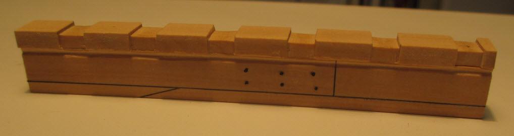
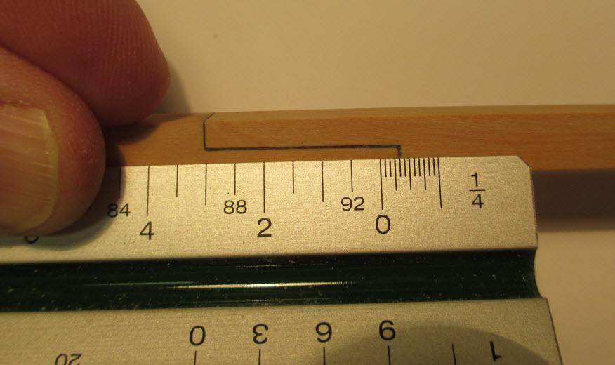
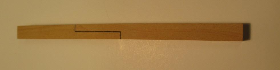
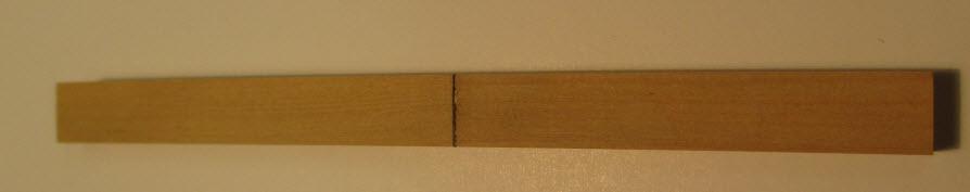
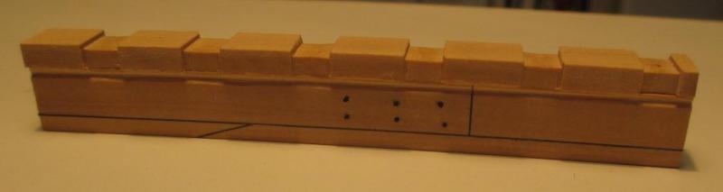
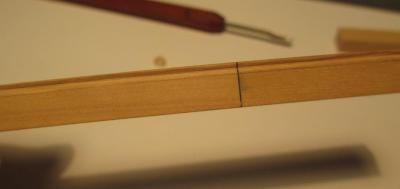
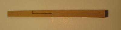
Scarf Joint Today I tackled the scarf joint. Like the rising wood my table saw came in very handy. To druxey's point you can certainly do all this by hand but for jobs like this power tools make the job a lot easier and in my opinion, more accurate. The boxwood provided for this exercise is milled to some pretty tight tolerances, for example I used a digital caliper to measure the two keel pieces that I used so that I would know how deep to make the cuts. One piece was .2550" and the other was .2535". I divided those dimensions in half and first cut to almost the center of one then adjusted the blade ever so slightly to cut to the center of the second. Cutting to such close tolerances is certainly doable by hand but not by someone like me, without the ability to make the tiniest adjustments I'd be sunk. I've been a wood carver for years and am used to eyeballing things, it if looks good, it is good. When I got into building ships I had to get used to measuring things. It took me awhile and a lot of wasted wood before I broke down and bought a mini-table saw (Micro Mark) but it has allowed me to do better work so I do understand Sarge's point. To start I held the two pieces, one on top of the other then slid them so the overlap was exactly 3' 4" on my architect's ruler. As carefully as I could I then drew a line on each piece using the end of the other piece as a guide. I then got to work on the saw and cut to the center of each piece based on the measurements I took earlier minus a couple thousandths. The saw leaves tiny ridges and by leaving a minute amount of wood I was able to sand them away so that when I ran my nail across the joint it didn't catch. I was happy. Here are those 2 perfect pieces: scarf1 Next I cut little pieces of thin black paper and glued them to the butt ends of the joints and even though it would never be seen, I also glued it to one of the interior faces of the joint. When I glued it all together I found to my horror that my perfect joint wasn't anymore, it was off by the thickness of the paper and glue. RATS! I made a mental note that when you measure things in thousandths of an inch the thickness of the paper really DOES matter. Lesson learned. After a little sanding I ended up with this joint: scarf3 This is all that will be visible once I glue the rising wood and false keel in place: scarf2 The spec calls for 3' 4" and that's what was delivered! scarf4 I really do appreciate the support and the photos from other logs otherwise there is no telling what would have been produced but I'm sure it would not have turned out so well, THANKS ! Next up is the rabbet.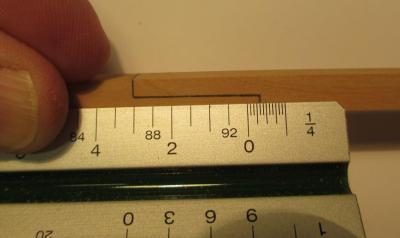

-
Hi Bob, Nice to see you are rebuilding your log. I've been following it for close to 2 years. Jim
-
Echo by Rustyj - 1:48 - cross-section
jml1083 replied to Rustyj's topic in - Build logs for subjects built 1751 - 1800
I'm with everyone else in thanking you for reposting Rusty. I'm one of those that learn my watching someone do something or seeing photos of the steps taken to reach an end. Having your log back up will be a very big help as I move forward with my Echo. I appreciate you taking the time to find the photos and upload them again. Jim -
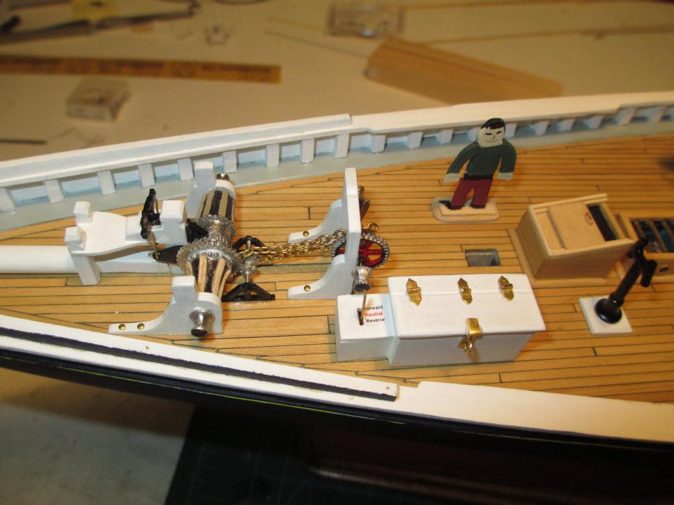
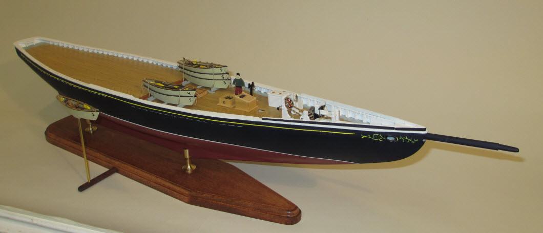
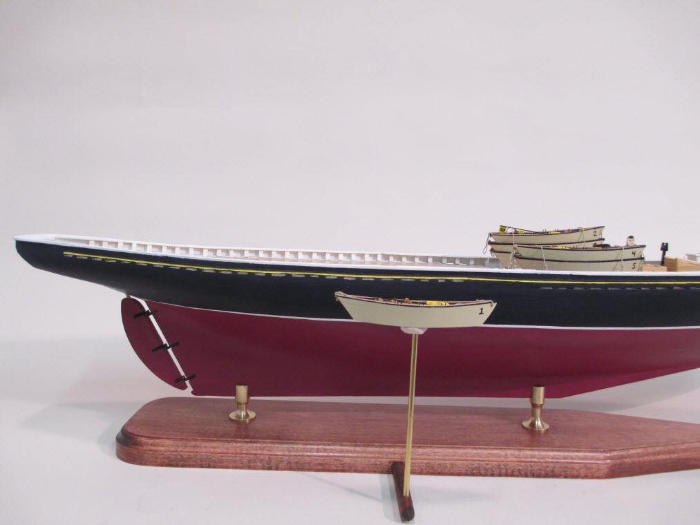
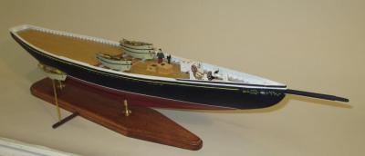
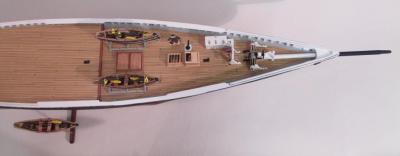
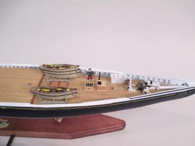
Jay, I composed my log using MS-Word. I insert the pictures into the document and then put a label under the photo so when it's time to upload I know which photo to use. I find the new software MSW is using is actually easier for adding photos. Here is how I do it: In Word I press <CTRL> A and then <CTRL> C to copy everything to the clipboard. In the MSW editor I press <CTRL> V to paste everything. You can't paste photos this way but the editor will show a little box where the photo goes and on the next line the name of the photo. To add the photos inline I then go to the area below the editor. One of two things happens and I haven't figured out yet why sometimes "A" happens and other times "B" but it is always one or the other so I'll explain both. Option "A" has a very obvious Add Photo option below the editor. Click on it and you'll be in a windows box where you can select one or all of the photos you want to upload. Once you've made your choice(s) you'll be back at the editor screen. Option "B" has the option for adding photos hidden. Below the editor window, towards the right side of the screen you will see a button for "Other Reply OPtions" or something to that effect. Click this button and the editor will refresh and now the button in Option "A" is visible. After you have done either A or B as appropriate you will see all of your photos listed one above the other just below the editor window. Scroll to the point in your post where you want to add a photo, click your mouse button to mark the spot and then click the option below the photo to "Add to Post". That's it! Hope this helps. Recent Bluenose work: Recently I've done some work on the foredeck of my Bluenose. The project has reached the point where the ship really needs somebody keeping watch on things. Meet Jacques, my scale deck hand. That's him standing next to the skylight. He stands a scale 5'10" and he can be found all over the ship. I find him especially useful when trying to visualize how something would look in real life. At those times he stands tall and I can usually get things sorted out pretty quickly. 20130128-a This shot of the foredeck shows everything I've done since my last post. The skylight and companionway are both made of boxwood from Hobby Mill. The bars on the skylight are 3/64" brass rod. You can't see it in this photo but the inside of the skylight is lined with blue foil and if you look straight down you see gold textured foil - this is done instead of painting everything inside black, it adds a little interest. The interior companionway sides are painted black and at the bottom you will see the same gold foil. I didn't want to have the sliding top all the way closed, nor did I want it all the way open. A normal person would say then leave it half open/closed depending on your point of view. I wasn't sure I liked that either so the sliding top does just that and you can open it or close it as weather conditions permit. Not sure what that will be once this is under glass but I will (probably) glue it at that point. There is a lot going on with the hoisting engine and assorted equipment. I was bored one night so I sat with a triangle jeweler's file and went to work on the large gear. I liked that so much I did the same thing on the smaller gears, the ones that are connected with chain. After filing all the teeth I rolled it on a piece of thick paper with a little pressure so that it left impressions where the teeth were. I measured 1" and that gave me the chain size I needed. I forgot what that is and the paper is lost but I found that in my box of odds and ends I had a chain that was almost the exact size I needed. Jacques put up a fuss that it wasn't EXACT but that's life. When I was in the Navy we used to say "good enough for government work" and so that is what the chain is. This next shot is taken from the port side and gives a better view of the engine housing and the associated hoisting equipment. The label on the hoisting engine box was created in MS-Word using 5pt font. This was done on a whim and I wasn't sure I would use it until I cut it and put it into place, it looked so good that I kept it. The 3 positions are: Forward, Neutral and Reverse. The label is for the benefit of new hands least they kill someone by throwing the hoist into the wrong direction. The hinges and hasp on the engine housing were cut from a sheet of .005" brass. 20130128-e The next photo is taken from the perspective of another fishing boat off the starboard side. The base is rock maple with a mahogany stain. Into the side of the base I drilled a hole for a dowel and into the dowel I drilled a hole for a brass rod. On the end of the brass rod is one of the dories, fully outfitted as if was being hauled back aboard after a (successful) trawl. The dory is displayed at the waterline. This photo also shows the installed rudder. I used 3/16" pintels and gudgeons from Bluejacket Ship Crafters to mount it. 20130128-b The next photo is a seagull's eye view of the foredeck with the dory along side. 20130128-c This final shot is just a different view of work done so far. 20130128-d I've just started work on the fife rail, the boom sheet buffer and the jumbo jib boom traveler block. Jim


-
Hi Dave, Thanks for posting links to the photos of your build. I had been following it and looking to it as a reference as I work on my Bluenose. Keep up the great work! Jim
-
Hi Jay, Good to see you're back with your Conny. I'll be following your progress. Jim
-
Here is an unusual piece of Naval history. I am a plank owner on the USS Cook DE-1083 (later FF-1083). The Cook was named for LCdr Wilmer Paul Cook, an A4E pilot from Attack Squadron 155 off the USS Coral Sea (CVA 43). He was shot down over North Vietnam on 22 December 1967. He was listed as Killed In Action / Body Not Recovered (KIA/BNR). He remained in that status until June 21, 1988 when the Vietnamese government returned his remains. His family requested that he be buried at sea and on November 27, 1989 his ashes were scattered at sea off the coast of San Diego, CA from the ship named in his honor. It is believed this is the only case where a service member's remains were buried at sea from a ship named after him.

-
Echo by jml1083 - cross-section
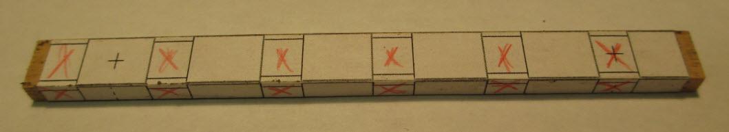
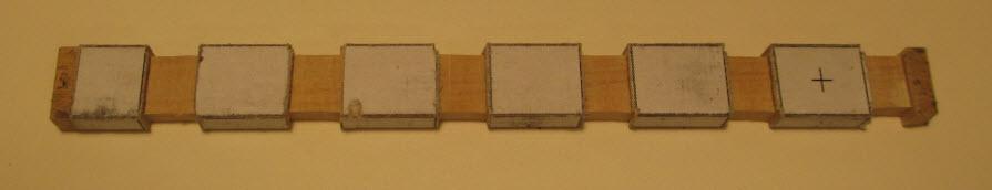
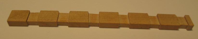
jml1083 replied to jml1083's topic in - Build logs for subjects built 1751 - 1800
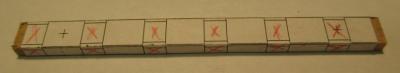
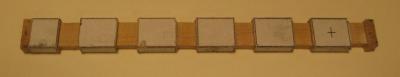
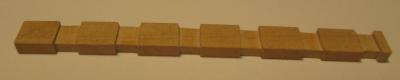
Rising Wood Hi guys, Thanks for checking in. I was able to get a little work done today so here goes! I started work on the rising wood by making a couple copies of the illustration that I downloaded from Admiralty Models website. I checked to make sure the sizing was accurate by using the 3" standard on the sheet. Then I cut out the top view and side view cutting exactly on the lines. I rubber cemented the top onto one of the pieces of boxwood supplied. Then I rubber cemented the side piece. When I tried to cement the other side I realized that it would be upside down as what works on one side will be backward on the other. At this point I had a couple of options: I could put a piece of carbon paper with the carbon side up under the sheet and then trace the lines which would give me a mirror image on the other side of the paper. Even with a sharp pencil this would result in a thicker line than I felt comfortable with. Accurately marking out the lines is critical and a fat line leaves lots of wiggle room. I opened the PDF again on my computer and selected Print but before actually printing it I checked the "print options" and found that the printer had a "mirror image" option. I selected that and printed a perfectly sized template for the other side. I ended up with is a scantling with the top and both sides covered with paper with an outline of what I needed, here is what it looked like: The red "X" denotes a piece that needs to be removed. I set my table saw to approximately 1/32" and cut a piece of scrap and adjusted the blade height until the depth was exactly 1/32". I ran the piece over the blade multiple times until everything in a section was removed, then I moved on to the next. I then flipped the wood up on one end and did the same thing to remove the wood from each side. After removing everything this was what I was left with. Having used rubber cement to glue the paper to the rising wood made it easy to remove what was left. I used a small file to remove the slight imperfections from the bottoms of the cuts left from the saw kerf. This is the end result Tomorrow I plan on working on the scarf joint.