jml1083
-
Posts
195 -
Joined
-
Last visited
Content Type
Profiles
Forums
Gallery
Events
Everything posted by jml1083
-

Echo by jml1083 - cross-section
jml1083 replied to jml1083's topic in - Build logs for subjects built 1751 - 1800
Hi druxey and Greg, Thanks for the tips. I had actually started with 150 grit on a very old sanding block from X-Acto. The block is only about 4" long and I kept knocking one end or the other into frames - if I kept it up it would only be a matter of time before I broke something. Also, using 150 was pretty slow going and I began calculating in my head how old I'd be when I finally got finished. I'll put both of your tips to work tomorrow night when I get home from work. -
Hi Ben, Looking good! You're on your way. Here is how I went about the chocks: I glued my frames up right on the paper template, this way I was sure nothing got knocked out of whack. Where the chocks are I cut an oversized hole in the template BEFORE I edge glued the frames. I edge glued the parts of the frames that touch and waited for the glue to dry. I then CAREFULLY placed the template with the hole for the chock over the piece of wood the chock would be cut from. Using a very sharp lead I traced the outline right from the frame pieces themselves. I then sanded almost to those lines on my Byrnes sander. Once I was close i made very small adjustments with the sander until the chock fit tightly into the space allocated for it. There was always extra wood on what will be the inner most surface of the chock and that's what I used to guide the chock into the sander. It took a couple tries until I got good at it but once i did the pieces almost snapped together and more than one I had trouble removing a chock so I could add glue. I treenailed all of my chocks using boxwood treenails. I started with 1/32" x 1/32" boxwood and pulled them through a Byrnes drawplate. Some people don't like making them but I found it relaxing. Good luck, you're off to a good start.
-
Echo by jml1083 - cross-section
jml1083 replied to jml1083's topic in - Build logs for subjects built 1751 - 1800
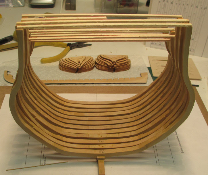
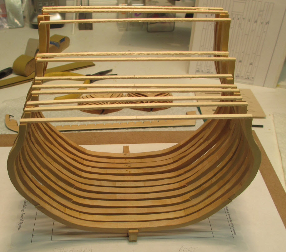
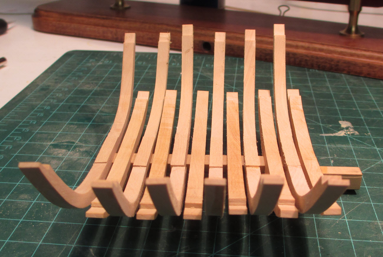
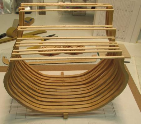
This week I finally raised the last of the frames! Broke one in the process through unintentional rough handling. Next steps are to install blocks between the frames to stiffen things up a bit then I'll start fairing the hull. Fun times with sandpaper ahead. all_raised_frames_1 Looking through the frames you can see the start of my next project, A group build of Chuck Passaro's English Pinnace. A number of the members of the Ship Model Society of NJ are doing this as a group project. all_raised_frames_2 Greg, having the center line drawn on each (temporary) support goes a long way to keeping things lined up but even with that there will be a lot of sawdust generated.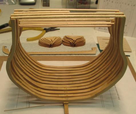
-
Echo by jml1083 - cross-section
jml1083 replied to jml1083's topic in - Build logs for subjects built 1751 - 1800
Thanks druxey. I WISH I had gone away but in my case work is what's keeping me out of the shipyard. -
Hi Mike, I recently got the 5400 with the "A" package. I added a lot of extras like the tilt angle table, rotary table, right angle attachment with tailstock and the sensitive drill attachment. All in it was about $1950 with shipping from CA to NJ. When you are looking at the cost make sure you factor in any goodies you'll want as they can add a lot to the price but they also add all sort of extra functionality. When I first got it I took baby steps but quickly got into more complicated (and precise) setups. For my use CNC was above and beyond what I could justify. Get the book on table top machining with your mill; what you can do with the mill is limited only by your imagination. For example, using Chuck's jig you can make some incredibly small but perfectly formed blocks and crank them out by the hundred. Oh yeah, I LOVE IT!
-
Echo by jml1083 - cross-section
jml1083 replied to jml1083's topic in - Build logs for subjects built 1751 - 1800
Slow progress but progress nonetheless. All frames have been treenailed using .0032" boxwood treenails. What a pleasure using Jim Byrnes's drawplate. Each frame as a piece of basswood glued to the top. The centerline is drawn on this piece and that is used as a guide when I position the frames. All frames have been sanded and one coat of sanding sealer applied to all the surfaces that will be impossible to get to once frames are raised. Speaking of raised frames, here are deadflat0 and deadflat1. The frames are attached to the keel using .0035" boxwood treenails and yellow wood glue. 2_frames_a.jpg 2_frames_b.jpg As they say in the cartoons, "that's all folks".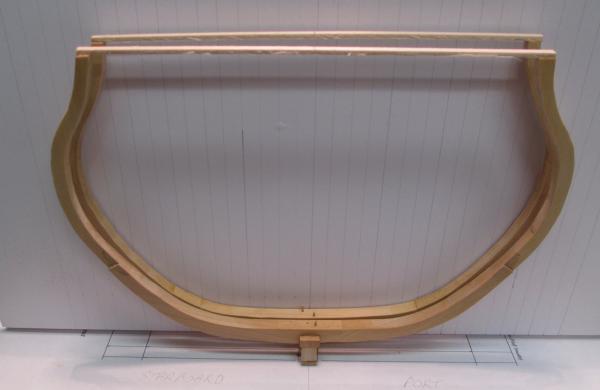
-
Hi Dave, Your Bluenose is looking very good. When it comes to drilling the holes for the screws I used finer thread sheet rock screws than the ones that came with the pedestals. I got mine from Bluejacket and they fit the hull just right. I drilled the holes in the base first and then put the pedestals and screws in place. I then placed the model into the slots and put a little downward pressure to mark where the holes had to be drilled. As others have suggested, I drilled small holes as well. I also squirted CA glue into the holes and let it dry. This made the wood of the keel stiffer and gave the screws a better bite. I made the mistake of making my case out of 1/4" glass and it weighs a ton. I had it in a show recently and when I got home I noticed that a barrel had come loose during transit and when I tried to get the cover off I found I couldn't get my arms around it and still be able to lift it high enough to remove it. It is literally a 2 man job. Next time I will use 1/8" glass all around and maybe a bit heavier on the top to protect it from anything falling on top of it and breaking the glass. Having 1/4" glass on the side is overkill. I really like the idea of displaying the block.
-
Echo by jml1083 - cross-section
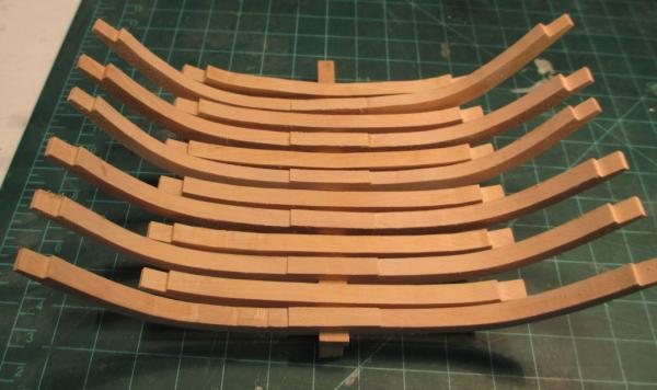
jml1083 replied to jml1083's topic in - Build logs for subjects built 1751 - 1800
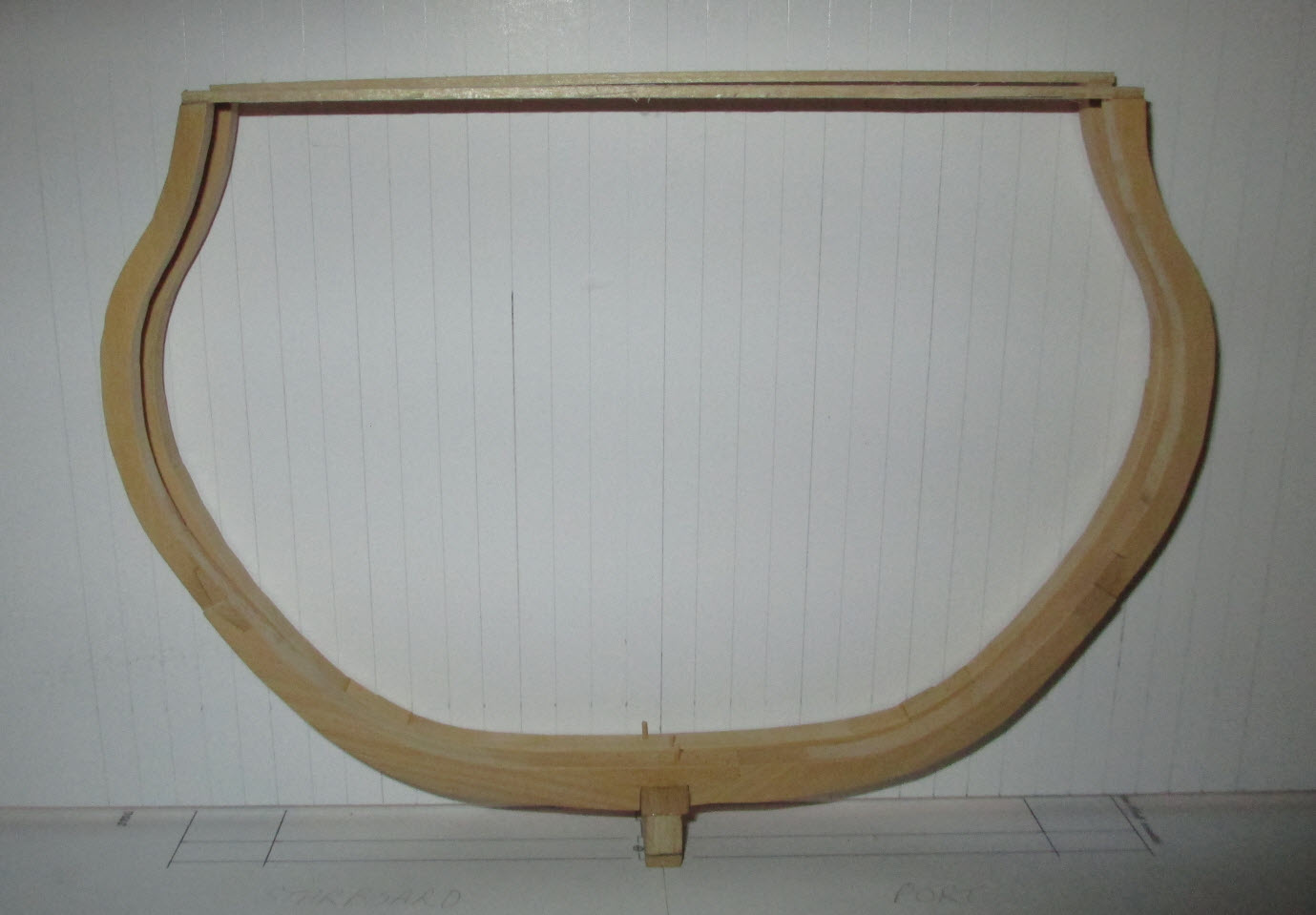
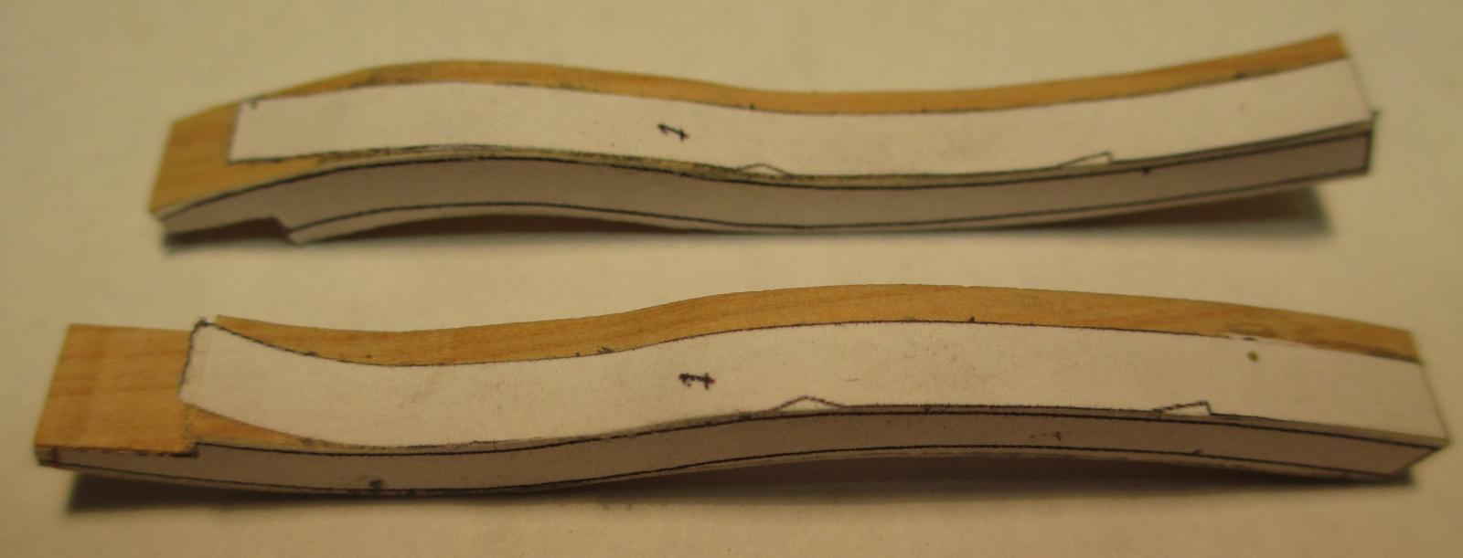
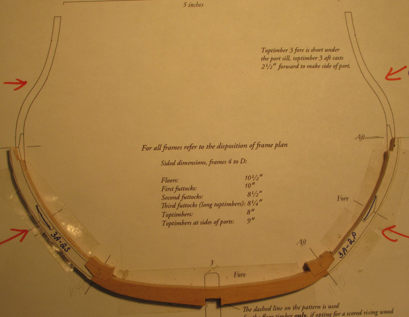
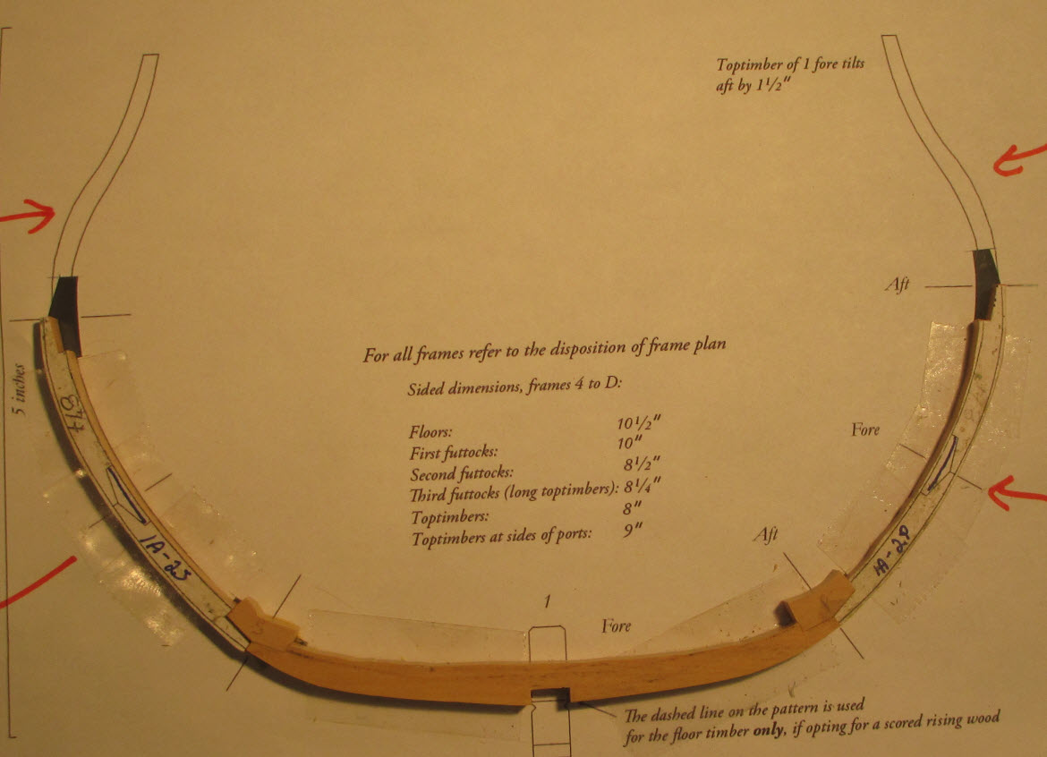
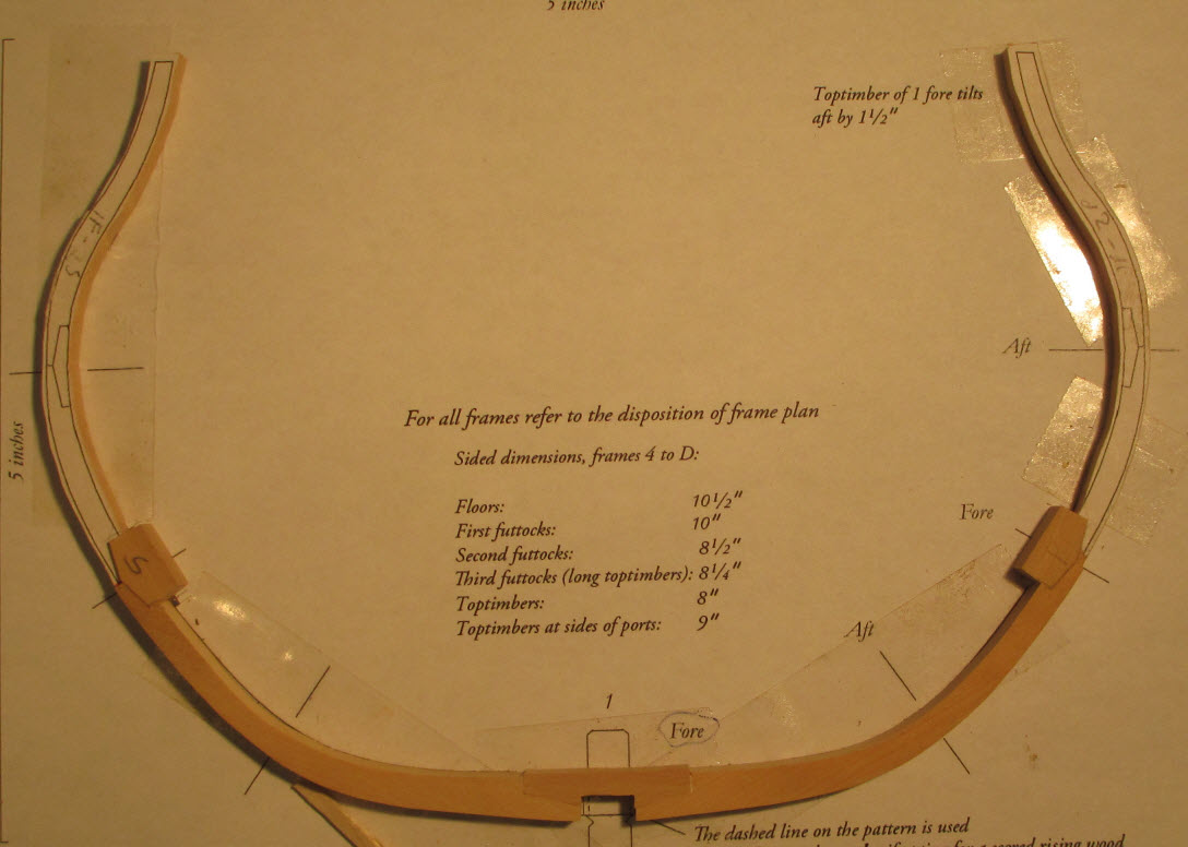
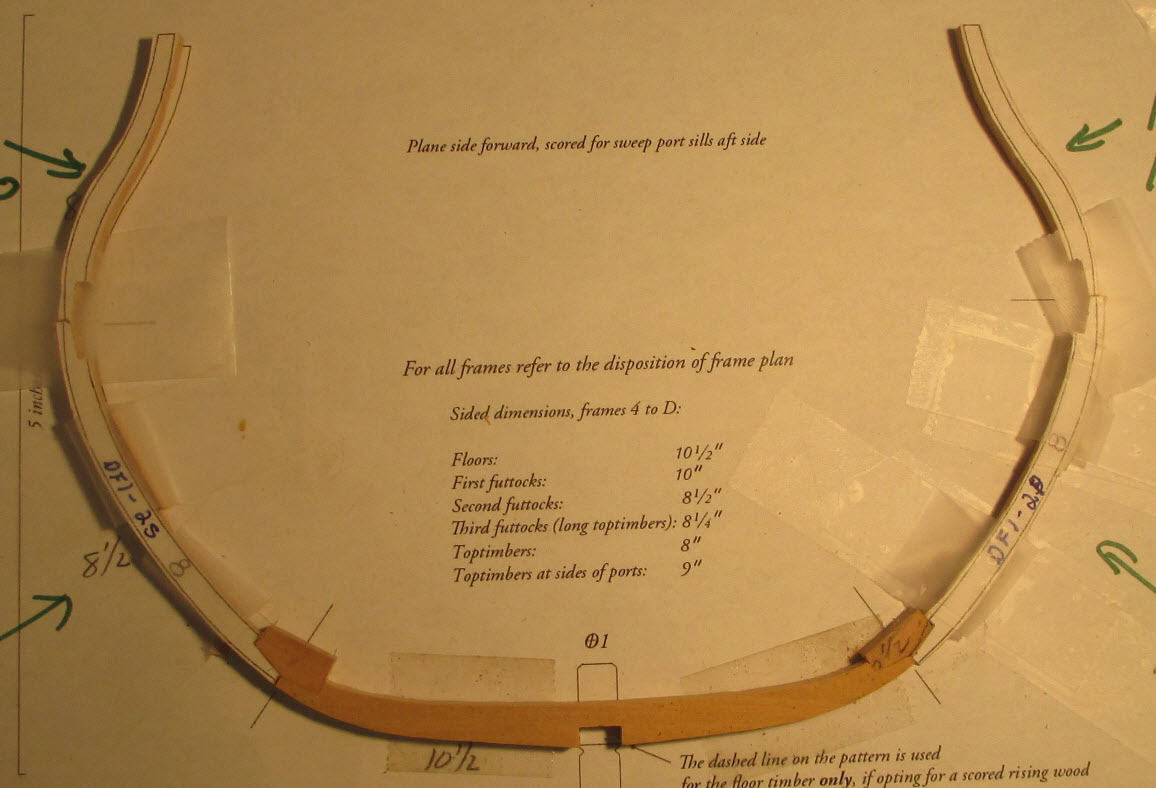
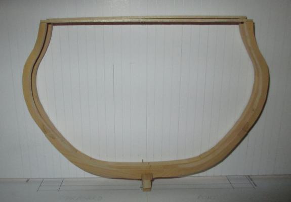
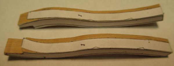
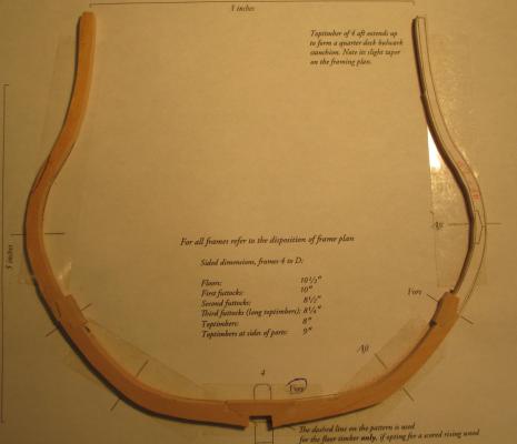
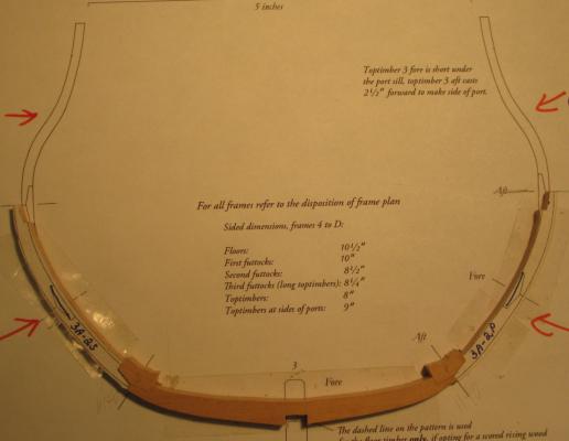
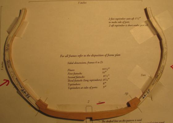
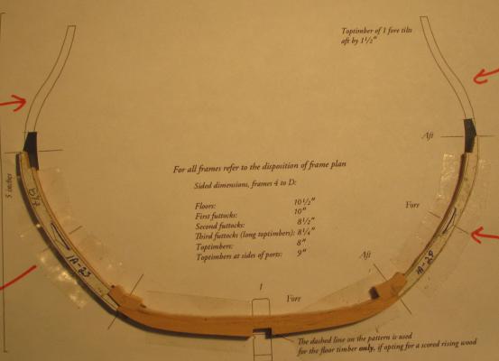
This weekend I finished the last of the frames. 3-Aft was the hardest with the most significant cast. cast frames.jpg Here is what they look like positioned on the keel. Some need more sanding than others before they can be raised and faired. I also have a lot of holes to drill for the treenails which I made on Saturday using boxwood. all frames. jpg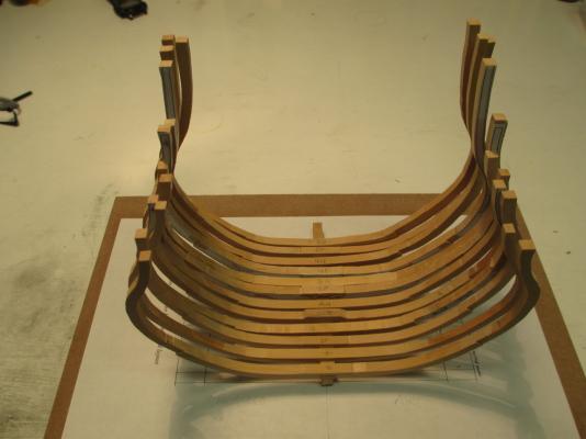
-
Echo by oneslim - cross-section
jml1083 replied to oneslim's topic in - Build logs for subjects built 1751 - 1800
Bob, druxey and Maury, thanks for the info. I'm using rubber cement so naptha is what I'm after. Back in my cabinet making days we used huge amounts of contact cement and used hexane as a release agent. Found out years later that can cause nasty neurological problems.Live (and hopefully) learn. -
Echo by Maury S - FINISHED - Cross-Section
jml1083 replied to Maury S's topic in - Build logs for subjects built 1751 - 1800
Beautiful workmanship Maury. -
Echo by oneslim - cross-section
jml1083 replied to oneslim's topic in - Build logs for subjects built 1751 - 1800
Hi Bob, thanks for the tip about the tape residue; haven't had much of a problem with it but one piece that was held for a considerable period of time did have a tack to it when I finally removed it from the paper template. In a similar vein, do you happen to know what solvent should be used to thin Elmer's contact cement? I bought a new bottle when I got home from the workshop and despite my best efforts to quickly close the bottle after each use the glue it starting to get thick. Good morning druxey. I have a long weekend ahead so I plan on spending a good deal of time down in the shipyard and cast frames are very high on my agenda. I'll keep my wits about me as I layout these members. I hope to have photos by the end of the weekend. -
Echo by oneslim - cross-section
jml1083 replied to oneslim's topic in - Build logs for subjects built 1751 - 1800
Eureka Bob! Thanks for the photo of the cast toptimber. I can't tell you how many attempts I made at this and how many times I tossed the result. Too bad it is early in the day as I would love to run home right now and give it another try. A picture truly is worth 10,000 words. -
Echo by jml1083 - cross-section
jml1083 replied to jml1083's topic in - Build logs for subjects built 1751 - 1800
Mark, Druxey, Bob & Greg, I found that missing DF0 and it was hidden for good reason. I recut the first futtocks for it and the chock last night and then assembled the three pieces. The joints are virtually invisible so I'm happy. I have to figure out how much will be covered by planking (and which parts) so that I can determine which fame components, although not perfect, are good enough since they won't be seen. I don't want to fall into the trap of constantly rebuilding each piece otherwise I'll never get to end-of-job on this. Initially it was not my intention to go any farther than raising the 12 frames because I was approaching this as strictly a learning experience. As I get more into it, I am learning to naturally look ahead which is a critical skill if I want to take my ship building to a higher plateau. Continueing this build through planking and fitting out will continue that learning for me and has the added benefit of producing a nice looking model in the process (I've been following Maury's very impressive progress). I hope to get a few more frames completed by the end of this coming weekend (more likely if the NE USA gets rain on Saturday) and then I'll have some more photos. -
Hi Dave B, When you go to the hotel website make sure you type NRG in the group code box to get the discount. I booked my room about a week ago on their website and had no problem getting the single room rate.
-
Echo by oneslim - cross-section
jml1083 replied to oneslim's topic in - Build logs for subjects built 1751 - 1800
Beautiful work Bob, it is really coming along! -
Echo by jml1083 - cross-section
jml1083 replied to jml1083's topic in - Build logs for subjects built 1751 - 1800
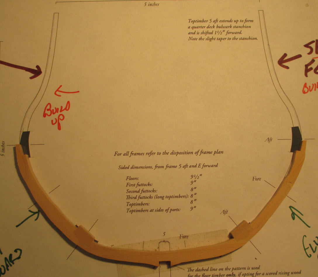
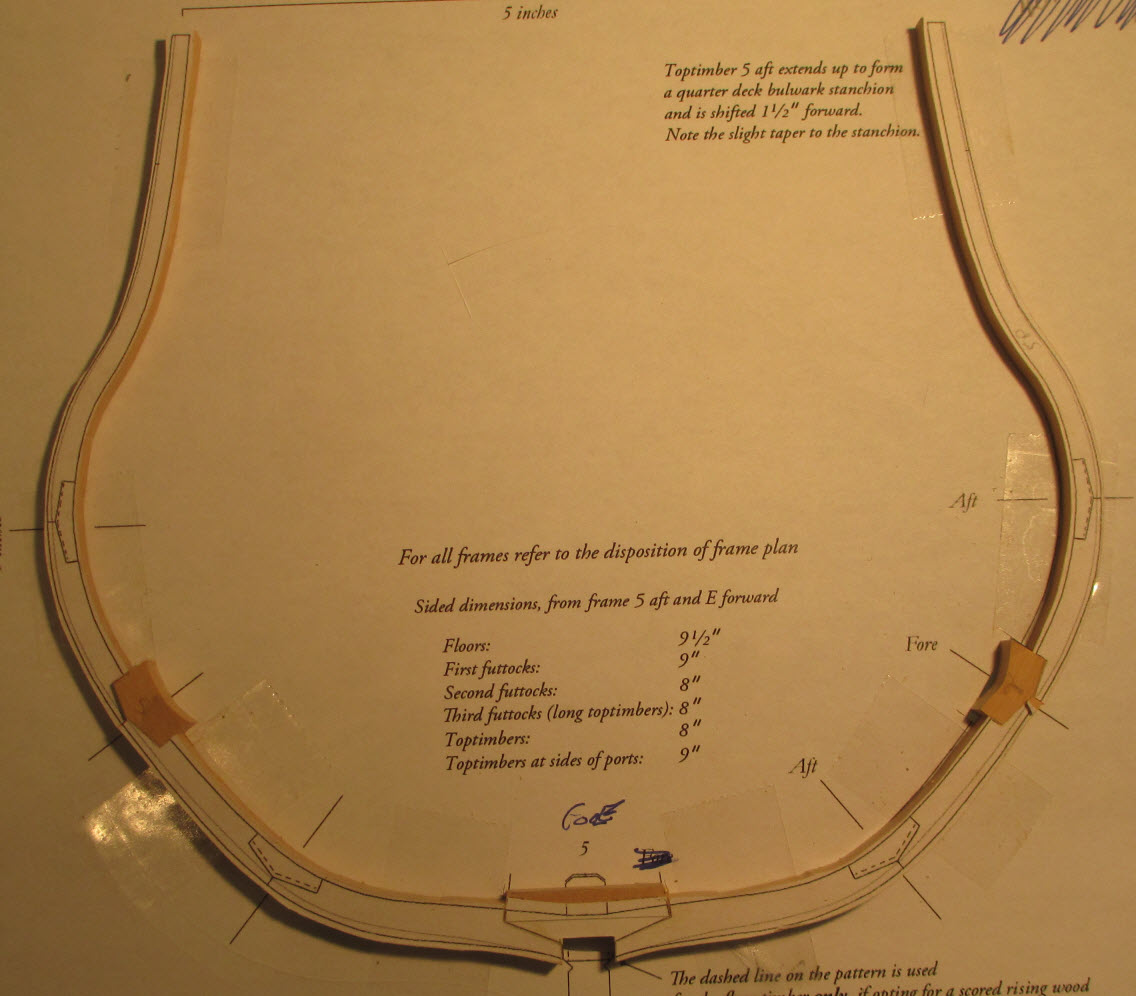
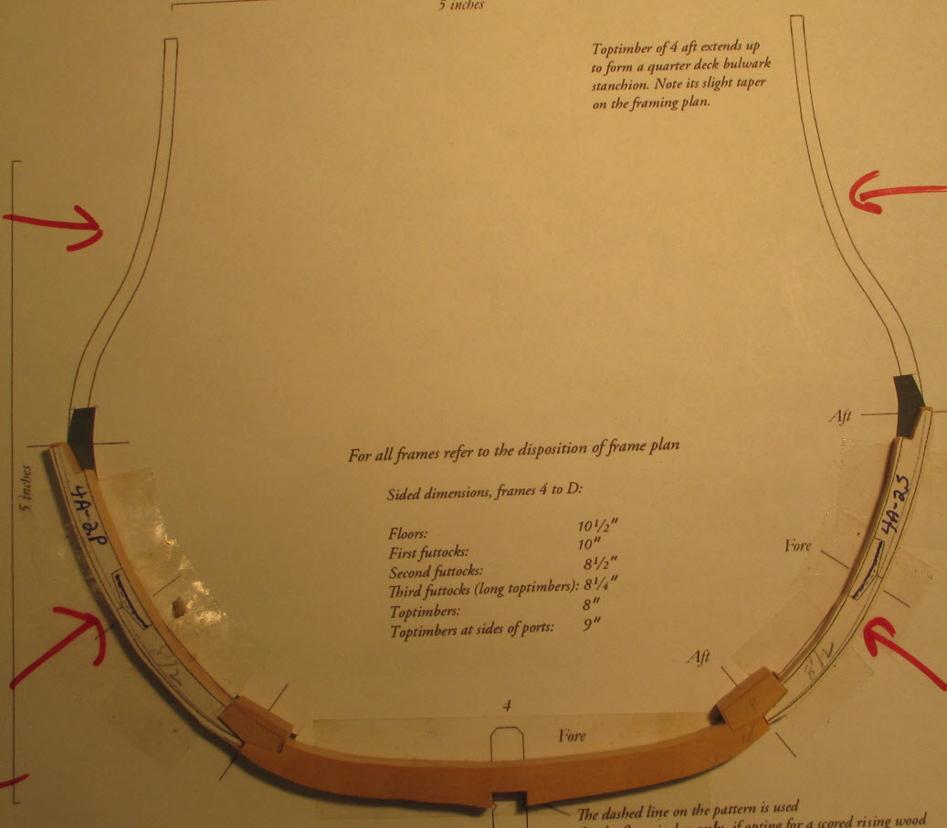
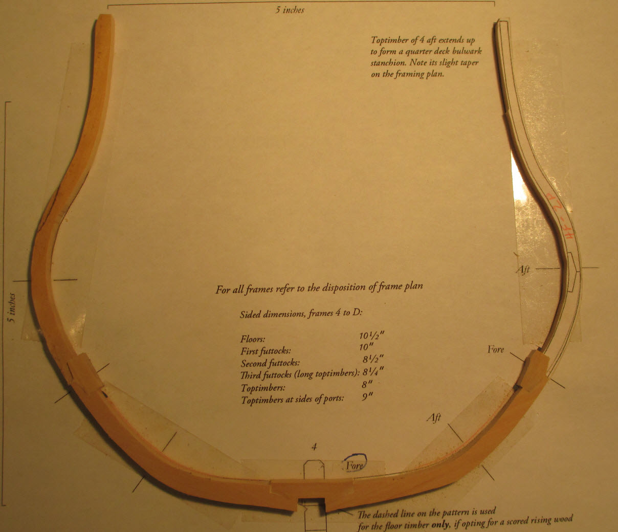
If time truly flies when you are having fun, I must be having a ball because I have no idea where the last 2 weeks went. The following photos show my progress to date. Starting forward and working my way aft we have: deadflat 1 - I have to add chocks to this. All joints are glued and tape keeps things flagged as fragile until I can add the chocks. It looks as though the top of the starboard side is out of alignment, that is the gap under the piece as well as a dollop of parallax. 1 forward - complete except to sand down the chocks. I left most proud because it made them easier for me to handle. They will all pay a visit to the oscillating sander before long. 1 aft - top timbers still needed. 2 aft - complete. 3 aft - top timbers needed. 4 forward - complete 4 aft - top timbers needed. 5 forward - complete 5 aft - top timbers needed. You may have noticed that deadflat 0 is missing. I noticed that too. I suspect that I pulled it out of the line up when I noticed some imperfection. Since this is my first effort at this sort of thing as I learn my work gets gradually better. A piece that early on was shown with great pride to friends and neighbors and anyone I met on the street doesn't pass muster a week later. I think that is called progress. During the workshop Greg told me (several times) to leave a little meat on the pieces when I sand so that I have something to work with when it comes to fairing the hull. Back when I was a cabinet maker I'd be presented with a piece of wood with a line drawn on it. I'd ask the person giving it to me if he wanted me to leave the line, divide the line or erase the line with the cut. Leaving more than a whisper of wood outside the line is a habit I'm having trouble breaking. Maybe when it comes time to fair this I'll learn. Still learning. Still having fun learning!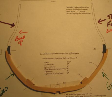
-
Hi Sarah, Looking good! Unfortunately poor wood quality is more and more common. I really liked your idea for holding the rubber bands together using little clamps. I learn something new every day and that's why I stop by MSW every day (actually multiple times per day)
-
Beautiful work Dave! I'll be following your progress.
- 43 replies
-
- 1
-

-
- bluenose
- model shipways
- (and 2 more)
-
Hi Ken, Your AVS is coming along very nicely. I did my chainplates the way you did yours. After forming them I filled in the valley between the two pieces of wire with silver solder that I then filed smooth. I'd like to post a build log for my AVS but like MSW I also have had a fatal hard drive crash. I back everything up (or so I thought) but when I did a restore to a new drive I found that the folder that had all my AVS stuff in it did not have that all important little checkmark to signify I wanted it backed up. Jim
-
Echo by oneslim - cross-section
jml1083 replied to oneslim's topic in - Build logs for subjects built 1751 - 1800
Hi Bob, Came back to revisit your log, good thing I did. Somehow I missed your great idea about using double sided tape to hold pieces to the templates. I'll have to give that a try. The rubber cemet works well but does leave a residue that has to be dealt with. Thanks for the tip! -
Echo by jml1083 - cross-section
jml1083 replied to jml1083's topic in - Build logs for subjects built 1751 - 1800
Hi Druxey, with age comes wisdom, at least I hope so, you don't get much in the bargain. Some of the wisdom I've gotten over time is learning that I have limits and sooner or later accepting them. I use power tools to augment frailties that cropped up over time. When I carve, which isn't often anymore, I still use my hand chisels and lignum vitae mallet. Years ago I had an opportunity to try a pneumatic carver and hated it because I couldn't feel the cut of the wood like I could with hand chisels. Sometimes you have to compromise or give up and since I don't like giving up things I enjoy, I adapt. Power tools are one of those adaptations for me. All things being equal I'd much rather be able to build my ships without power tools, if nothing else for the extra bragging rights. I saw David (Antscherl) work with his chisels and it was wonderful to watch. For me, watching a fine craftsman with his tools is one of life's joys. Greg, Ben and Rusty, yep it IS coming along which is more of a surprise me than probably anyone else. This is a really enjoyable build partly because before I went to Greg & David's workshop I didn't think I could scratch build anything more complex than firewood. My biggest challenge is understanding the drawings. Prior to this I had completed the Armed Virginia Sloop using a Bob Hunt practicum and on my own I built Midwest's Muscongus Bay lobster smack. Going from those to the drawings that we build the Echo from is quiet a leap. To me being difficult does not mean not fun, to tell the truth I think 90% of people who build ships would walk away from the hobby if they woke up one day and everything was suddenly easy. It's the problem solving, I think, that draws a lot of us to the hobby. That's it from here. There's a cast 3rd futtock shifted long top timber floor with my name on it so I better get back to work. Only kidding Greg, even I know that a cast and shifted 3rd futtock top timber floor can't also be long -
Echo by jml1083 - cross-section
jml1083 replied to jml1083's topic in - Build logs for subjects built 1751 - 1800
Thanks Greg. Once the tool issues were resolved I was able to make some real progress. I'm waiting on wood for the masts and spars on my Bluenose so for the time being all time spent in the shipyard is dedicated to the Echo. I'm having a lot of fun with it. David would say that I have fully crossed over to the dark side. I tried a number of times using chisels but more times than not either the fit was bad or the piece chipped with the last cut I made. I'm pretty quickly getting the hang of the mill and it allows me to do things that my shaky hands and arthritic fingers won't. The Byrnes disk sander is icing on the cake. I can consistently and accurately take off minute amounts of wood until a chock fits perfectly. -
Echo by jml1083 - cross-section
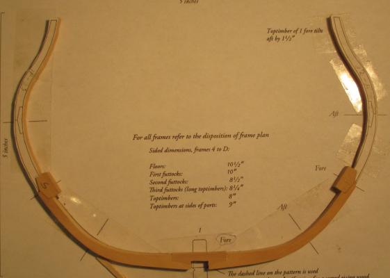
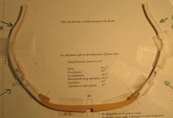
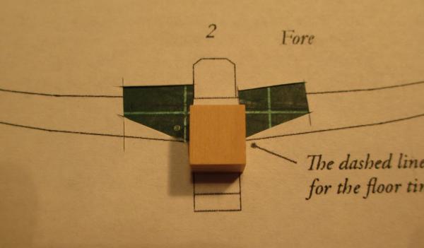
jml1083 replied to jml1083's topic in - Build logs for subjects built 1751 - 1800
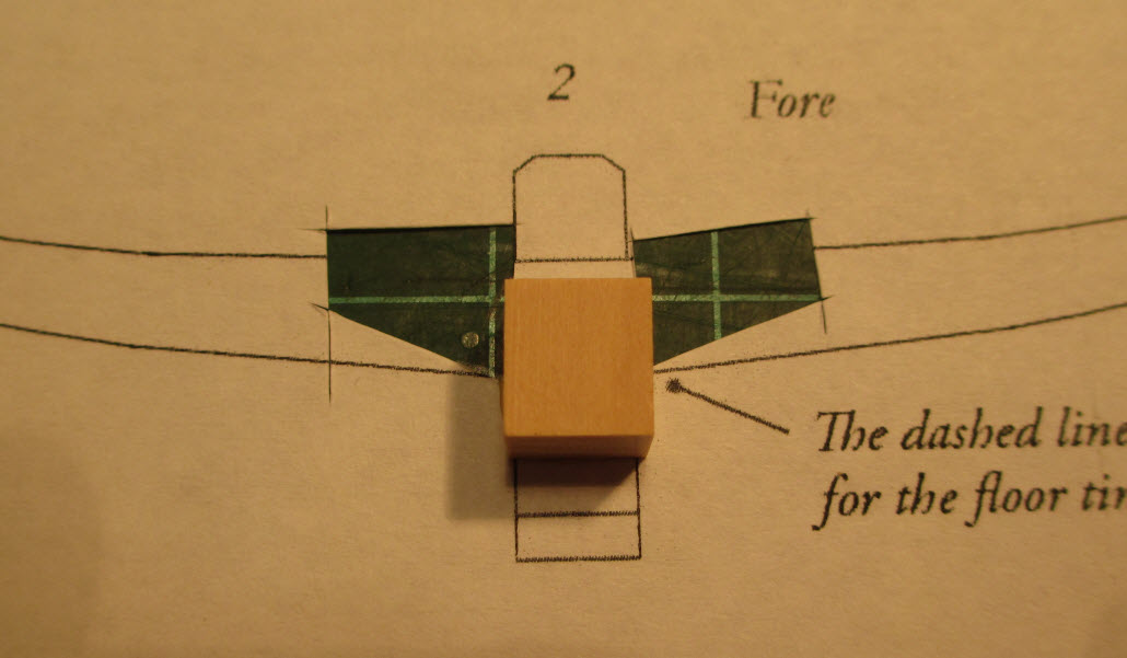
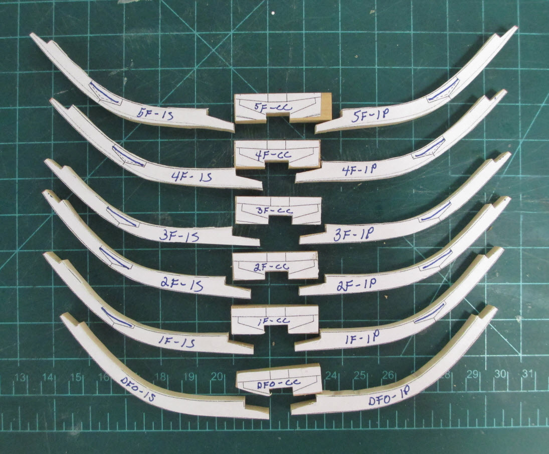
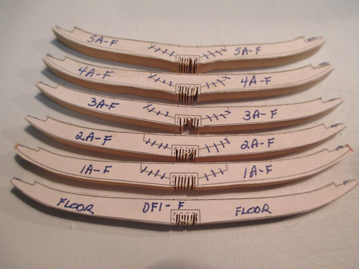
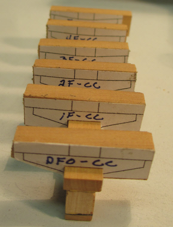
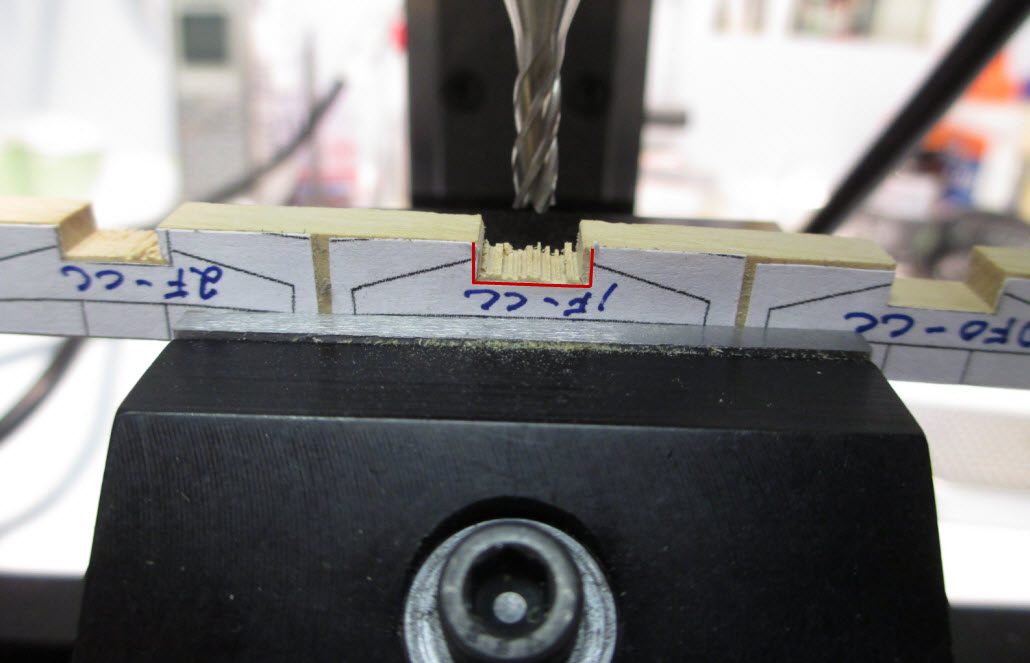
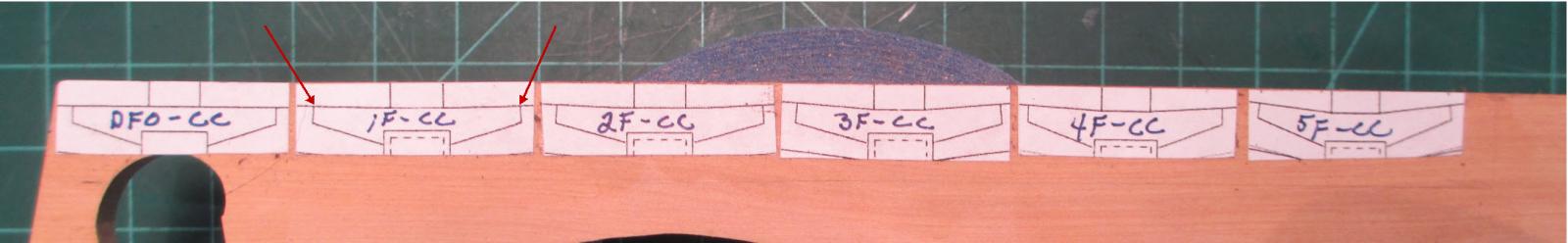
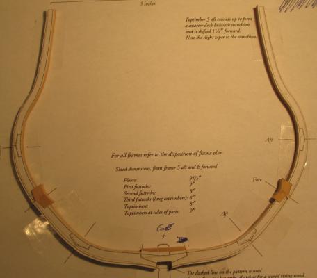
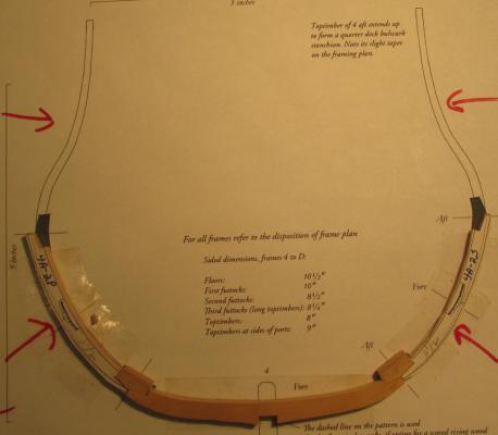
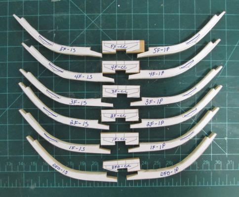
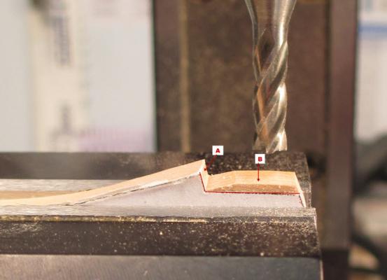
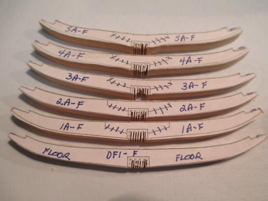
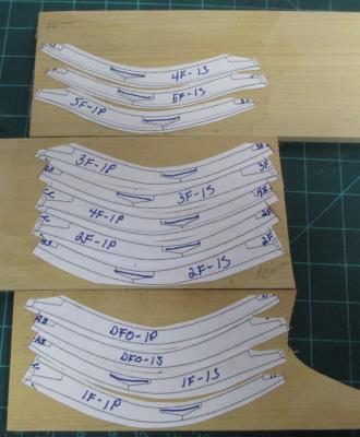
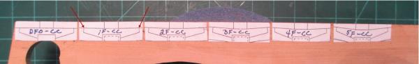
This past weekend I worked on the floor timbers as well as the cross chocks and first futtocks. I laid out the cross chocks in such a way that I could get the most work done with a minimum of set up changes, primarily on the mill. The following photo shows how I laid out the cross chocks to be cut. Once I rubber cemented the templates to the billet I made one long cut along the bottom and when I got to 5F-CC I cut this piece off. Now I had a narrow strip of wood with the 6 cross chocks in it. The next step was to cut up into the rabbet in the center of each chock. I did this on the scroll saw and made a number of cuts into each rabbet so what I ended up with was a number of very thin fingers sticking up – the look was that of a very tiny feather board. You will also notice 2 red arrows pointing to chock 1F-CC, I’ll explain those with the next photo. 04-16-13a In this next photo (04-16-13b) I’m milling the rabbets. I kept all of the chocks connected for this step as it’s easier to position it in the vice. To make my cuts more precise before I put the strip in the vice I used a #11 X-Acto blade to cut the paper template exactly on the lines that define the rabbet. You can see that here where I marked the cut lines in red. By cutting away the paper template I eliminated the fuzz that often appears when mill through the paper to get to the final line. With the template out of the way I was able to mill the rabbet with very tight tolerances. In the first photo I had 2 red arrows. These point to the top shoulder of each chock. When I put the long strip in the vice for milling I used these two points to accurately set up a level line for milling for each individual chock. With the work now square in all directions (I used a dial indicator to make sure) I milled the rabbets. You can see at the right side of this photo a completed rabbet, the middle is in the process of being milled and the one on the left is next. 04-16-13b After milling all of the rabbets I test fit them to the keel to make sure the depth was correct and also that the center of the chock fell exactly over the centerline of the keel. You’ll notice that I left a lot of meat at the top of the chock and also the sides and that I didn’t cut the angled parts yet. I did that later. 04-16-13c The next task was to cut the first futtocks. Using the labeling system I talked about earlier I marked up all the futtock templates, cut them from the frame diagrams and rubber cemented them to the billets. Layout was done to conserve wood and also minimize the cutting needed. In a number of cases I was able to place the templates close enough together where a single cut served as the bottom cut on one piece as well as the top cut on the one below it. 04-16-13d Here are the floor timbers. They were cut out using the same process as I used for the first futtocks. You can see that I again cut tiny slots where the rabbet will be milled. 04-16-13e I milled the scarph joints in two steps because the two faces do not meet at a 90° angle. Using my X-Acto knife I again cut right on the line for shoulder and face of the scarph joint as indicated on the template. Removing the paper from the area to be milled really made the machining process must easier. The first cut was to face “A”. When I put the piece in the vice I used the very sharp line where the paper was cut as a guide to locate the piece in the vice. The red line in the photo was positioned so that it was parallel to the top surface of the vice. After milling face “A” I repositioned the piece in the vice to mill surface “B”. In this photo you can see how the sharp line left were the paper was cut makes it very easy to position the piece in the vice. 04-16-13f First futtocks cut, sanded and scarphs milled. The rabbets are milled in the cross chocks. 04-16-13g Next I cut pieces of wood to simulate the keel and rubber cemented them to the frame drawing. The cutout you see was so that when I glued the cross chocks to the futtocks with wood glue, the glue would not stick to the template. After the glue has set I rubber cemented each of the futtocks to the frame template. I made very fine adjustments to the surfaces where the futtocks meet the keel to ensure the surfaces mated perfectly. 04-16-13h Somehow I did not get photos of the chocks glued to the futtocks. With the substitute keel in place and the futtocks butted up against it and glued to the template I fitted the cross chocks. First I sanded the sides to within a whisker of the vertical lines on the sides. I left more meat on the angled sections then I test fit the chock. I kept making very minor adjustments to the sides until the chock sides would fit into the gap. Next I sanded the angled sides, again making very minor reductions until the chock just fit. Once the chock was correct in all respects (except for the excess wood I left on top) I removed the keel substitute and glued the cross chock in place. I removed the substitute keel so the carpenter’s glue would not accidently glue the substitute keel to the chock or futtocks. After allowing the wood glue to dry I peeled the paper template from the assembled futtock. I took each completed floor timber or futtock and on the top of the rabbet wrote the frame number and an arrow pointing forward. With this marking made I removed the paper templates that were used to fabricate all the individual pieces. The next two photos show the final result. Nothing is glued to the keel in these photos and very minor shimming is needed on some of the pieces, this will be done when I permanently attach everything to the keel. You’ll notice that I left a bit of wood on the tops of the cross chocks when I sanded. This will allow me to make fine adjustments to how the piece sits on the keel, if I need the entire thing to sit a little lower I can remove a very thin slice of wood from the bottom of the rabbet. Once those adjustments are made the tops will be sanded so the tops of each piece are the correct height. 04-16-13i In this next photo some of the pieces look grossly out of shape but that is due to the photography and the pieces needing to be shimmed. 04-16-13j At this point I’m getting ready to make a lot of treenails and once that is done I’ll drill the necessary holes. After that I’ll start on the second futtocks for the floor timbers.


-
Congrates on all fronts Ben. I just got the Byrnes disk sander and it is amazing. Jim & Donna put their hearts and souls into their machines. You'll love it.
-
Jim Byrnes Model Machines
jml1083 replied to Mahuna's topic in Modeling tools and Workshop Equipment
Another very satisfied Model Machines customer checking in. Like many people, I work hard for my money and try to not spend it frivolously. When I first started building and was looking for tools I kept hearing about Jim Byrnes and Model Machines but when I looked at the prices I thought they were out of my price range so I bought cheaper. Big mistake. Over time I got to see and use some of Jim’s machines and realized that price differential was nothing compared to what you got for the extra money. I had purchased a drawplate someplace else and right away I found that as the diameters got smaller the accuracy got worse and worse until it got to the point where some of the smallest holes actually had a larger diameter than some of the “bigger” holes. Even still I figured I could make it work. At some point someone let me try Jim’s drawplate. WOW, what a difference. Yes, it’s just a piece of metal but it is a very precisely engineered piece of metal. I decided that it was worth it to upgrade. As noted elsewhere on MSW, Jim’s drawplate even comes with directions and care instructions. It is a simple concept beautifully executed. I did not discard my old drawplate, it sits on my bench and I use it as a paperweight and in that function it works perfectly. It is a constant reminder that even relatively simple things can be done extremely poorly or conversely as in the case of a Byrnes’s machine, extremely well. My next Byrnes purchase was the disk sander. As with the drawplate I got to use it before I purchased it. Being slightly older now and a bit wiser about smaller tools I thought twice about buying something cheaper and did not hesitate to buy the Byrnes sander. It has seen some heavy use since it arrived last week and I could not be happier. The accuracy you can get using one of Jim’s sanders can’t be duplicated on other, somewhat cheaper machines. Customer service as noted by others is on a par with their machines, the best in the business.