
Supplies of the Ship Modeler's Handbook are running out. Get your copy NOW before they are gone! Click on photo to order.
×

dgbot
-
Posts
3,993 -
Joined
-
Last visited
Reputation Activity
-

 dgbot reacted to Maury S in Echo by Maury S - FINISHED - Cross-Section
I'm re-painting the cannons per Greg's suggestion. Here's how it looks in the case. It's a "Football Display case" from Hobby Lobby. A piece of birds eye maple veneer held in place with Contact Cement (no warping this time). Just the right size. The officer in the foreground is cut from Chuck's Cheerful plans and glued to a piece if 1/4" wood...shaped a bit. No way am I going to try to carve one yet. It's a good prop to show the scale.
Maury
-
dgbot reacted to dvm27 in Echo by Maury S - FINISHED - Cross-Section
Cannon and carriages look very nice, Maury. I now use matte black automotive primer, several lightly sprayed coats, to blacken many of my brass items. It has the advantage of filling in small defects and blending mated parts into one. It also imparts a slight texture to the surface, which is reminiscent of iron.
-
dgbot reacted to JesseLee in Syren by JesseLee - FINISHED - Model Shipways - scale: 1:64
When I finally decided to tear off the cheeks & head rails I wasn't sure what I could re-do them with since I don't have a lot of milled wood to work with. I do have some lime wood & beech given to me by Dennis all the way from New Zealand. The problem with that was the upper head rail needs such a wide piece that none of these strips would work. I wanted to have all the cheeks & rails made out of the same kind of wood to keep the staining consistent so I had to find another option. I was going to look into getting a piece of poplar from Lowes like Piet told me about but I still haven't been able to get there yet (since being disabled from chronic lyme I can't drive anymore). So I rummaged through all the scrap I've got & found some blocks that were large enough for the upper rail. Don't know what kind of wood it is. It is hard but not real hard. The sawdust from it was yellowish. Anyway with nothing much but some small hand tools & a small hobby saw I painstakingly milled it down & cut & carved out the cheeks & head rails. This wood did so much better than the original basswood did but not as good as a harder wood would. I did have to harden it up some with watered down PVA when I cut the scroll lines. Much happier with these than the first ones.
Used some aluminum tubing for the hawse holes. Still working on the deck side of them.
Jesse
-
dgbot reacted to ollagynot in H.M.S. Triton (Cross Section) by ollagynot - FINISHED - 1:48
Thanks you for all the likes and comments so far! Finally got around to completing the lower deck today, ready to move on to making the lower deck spirketting and gun deck clamps. I decided to attempt to take some nicer photos (more in focus), most of the photos posted before where taken with a cell phone.
Thanks,
Tony
-
dgbot reacted to EdT in Young America 1853 by EdT - FINISHED - extreme clipper
Young America - extreme clipper 1853
Part 139 – Bilge Pumps 3
The twin pump flywheels were arguably the most beautiful feature on the entire deck with their graceful, s-shaped spokes. The wheels, almost finished and ready for mounting are shown in the first picture.
As can be seen from the underlying drawing in this picture, the wheels are 4’6” in diameter. The momentum created when rotating these large heavy wheels greatly assisted in the manual pumping effort. Pumping could be done with one or two men on each side. The curved spokes were more than decorative. Their purpose was to yield to the shrinking stresses created when the castings cooled – avoiding fractures.
I have been puzzling about how to make these for quite a while, considering the complexity of the spokes and the importance of symmetry in the final pieces. They were made in two phases. The first, described in this posting, used machines – including the most important (and most used) of those shown at the top of the above picture. Because all of my drawings show real world dimensions, scale equivalents had to be constantly calculated for machining adjustments. The drawings were tailored and dimensioned to support the machining process requirements. The second phase was done by hand and will be covered in Part 140.
The next picture shows a 1” diameter brass bar chucked in the lathe in the first machining step.
In this picture the piece has been centered, faced off square, center-drilled, drilled for the shaft and turned to the final diameter of 54” (3/4” at 1:72). The wheel is 4” thick overall with a 4” x 4” rim. In the picture the recessed spoke area is being cut out at a depth of 1” (.014” at 1:72) – from the inside of the rim to the axle hub, to allow for the final 2” thickness of the spokes. In the next picture, the wheel disk is being parted off.
The remaining machine work on the piece was done on the mill. For this work the rotating table had to be very precisely centered on the spindle so all the cuts would be concentric with the original turning. This centering is shown in progress in the next picture with the aid of the dial indicator.
I used a 3/8” milling bit holder chucked in the four-jawed self-centering chuck for this. The dial indicator is chucked in a spindle collet so it can be rotated. The small size of the Sherline mill sometimes requires ingenuity in coming up with dial indicator mounts. The bit holder is precisely concentric and worked well for this. After alignment, both x and y axes on the mill were locked to prevent accidental movement. The wheel disk was then placed in the chuck as shown below.
The face recessed in the lathe is downward. The surface of the disk is set precisely flush with the ends of the jaws.
The first machining steps have been completed in the next picture.
I designed the wheel to have an inside radius of 8” on each arc of the spokes and a spoke width of 2”. This required a special end mill. The one shown is .110” diameter (7.92”) - close enough. All the milling was then done by adjusting the y-table calibration wheels – after loosening the stop. After facing off the 1” recess, five holes through the spoke area were made at 72 degrees apart and flush with the inside of the rim as shown above.
Next, the cutter was moved in by 10” (.139”) and holes were bored on the same radius as the outer holes – flush with the axle hub. These holes are shown below after one more final machining step.
In this last step, the bit was returned to the outer position over one of the outer holes. It was then lowered and the table rotated 42 degrees to remove material between spokes at the rim. In the picture this work has been done and the chuck – with the piece unmoved – has been removed from the machine. So far, so good. The remaining hand work on the wheel will be described in the next part.
Ed
-
dgbot reacted to EdT in Young America 1853 by EdT - FINISHED - extreme clipper
Thanks again everyone.
Frank the soldering table is not an inexpensive tool and not an absolute must, but very useful and I think reasonably priced for the quality.
Bob, here is the link to the product page on the Contenti website:
https://contenti.com/soldering-n-joining/soldering-tools/soldering-boards/rotary-soldering-table
Ed
-
dgbot reacted to EdT in Young America 1853 by EdT - FINISHED - extreme clipper
Young America - extreme clipper 1853
Part 138 – Bilge Pumps 2
The next task on the pumps was to make the crankshaft/connecting rod assembly shown in the last picture in the last posting. This included the central supporting bearing pillar shown in that picture. That part was made first - as a tapered pier with vertical gusset supports in an X pattern. This provided an opportunity to use one of my new Christmas toys shown in the next few pictures.
In the first picture one of the side gusset plates is being silver soldered to the main central plate.
The parts are firmly held in place by the two articulating clamps that are mounted on either side of a rotating ceramic base. The clamp arms each have a pair of ball joints that can be tightened to hold the clamps very securely in any position. The clamp rods are tungsten, so there is no problem with heat. Also the stout handles do not heat up, so pieces can be unclamped immediately without risk of burns and the clamp springs are protected from overheating. For someone like me, with my shaky hands, this tool is a godsend – and just in time for the plethora of metalwork coming up. The torch is just a miniature propane torch. Oxy flame temperatures are unnecessary for most of this work. The next picture shows the pier subassembly held down on its baseplate for the next soldering step.
Because these assemblies will be blackened, I used Phosphorus-Copper prefluxed solder paste, which seems to blacken easier. It has a melting point of 1325 degrees F – about the same as medium (65%) silver solder.
In the next picture one of the connecting rods is being shaped after drilling of the bearing hole in a small piece of brass plate.
The connecting rods were then fitted with undersize “pistons” at their bottom ends. These fit very loosely in the pump cylinders to allow easy rotation. I did not attempt an authentic fit with these.
There are three pillow block bearings (sometimes called rhodings) that hold the crankshaft – one in the center and one mounted on each fore and aft fife rail. These were made by slicing off individual bearings from the soldered strip shown ready for the torch in the next picture.
The bearings are provided by the hole in the brass tube.
The crankshaft was formed from a length of .032” (2.5”) brass rod. The connecting rods and center pillar bearing had to be fitted to this before bending. In the next picture the crankshaft assembly is being test fitted to ensure unobstructed rotation.
The side bearings are clamped to the fife rails for this. I was very glad at this point that I did not opt for closer fitting pistons. In the last two pictures the crank assembly has been blackened and permanently installed.
The central pillar and the two side bearings were cemented in place with thin CA. So far so good. Now it was time to make the two delicately shaped flywheels that I hope will be the eye-attracting features of the pumps.
Ed
-
dgbot reacted to ggrieco in Heroine 1838 by ggrieco - FINISHED - Scale 1:24 - Western River Steamboat as she appeared before hitting a snag in the Red River
Thanks Tom,
One is going to be displayed at the Oklahoma History Center, next to the remains of the original Heroine, the other will go to the newly opened museum at Fort Towson. Fort Towson was the original destination of Heroine and only a few miles from where she wrecked. They also have a collection of some of the artifacts from the wreck.
-
dgbot reacted to ggrieco in Heroine 1838 by ggrieco - FINISHED - Scale 1:24 - Western River Steamboat as she appeared before hitting a snag in the Red River
The deck is finally planked on the first model and I've started on the second. Another shipment of boxwood arrived and I hope I bought enough to finish this time.
I did a little more work on the cam frames and started on the spokes for the flywheel.
Soldering the spreaders for the cam frames.
Completed cam frames. The cams were 24" X 24", the distance between the cam frames is 24 1/2"
Finally, one deck complete.
Flywheel spokes fresh from the mill. The channels for the spokes in the flanges were of different depths on the port and starboard sides requiring them to be cut slightly different.
The outer face was beveled slightly from 5 inches at the flange to 4 inches at the rim. The mill could only cut one side so the bevel was added later.
Test fitting the spokes. The mill cuts the interfaces so cleanly that there is almost no hand fitting necessary. This will save a lot of time on the 96 paddlewheel spokes when I get to them.
-
dgbot reacted to Mirabell61 in Majellan by Omega1234 - FINISHED - 1/200 - Luxury 37 m Motor Yacht - Miniature
Lovely fitting out Patrick,
the "boats garage" with the maintenance area and workbench look great .. (your imagination works splendid !)
Nils
-
dgbot reacted to Omega1234 in Majellan by Omega1234 - FINISHED - 1/200 - Luxury 37 m Motor Yacht - Miniature
Hi folks!
Thanks for all of your comments and Likes!
I've managed to do a bit more work on the lower deck's accommodation as well as detailing some of the engine bay's myriad of assorted cupboards, drawers and a work bench. To be honest, I really have no idea what the interior of the engine bay really looks like because no photos of the real ship's interior are available. So....I'm using my imagination and whatever information I can glean from photos of similar sized luxury motor yacht's engine bays on the internet.
Oh well, at least I'm trying to make it look convincing!
Cheers and all the best.
Patrick
-
dgbot reacted to flyer in HMS Pickle by flyer - FINISHED - Caldercraft - Scale 1:64 - my interpretation
Hi Jason
'less is more' is one of my favourite quotes as well. (If you look at the top of my head it might even be genetically built in.)
However sometimes it gets complicated in model ship building. It is not always clear to me if omissions in the kit or plans are because of kit costs, keeping plans simple by omitting self-evident details or because it really wasn't there.
One example was the belfry I added on Pickle. I assume any vessel of Pickles size would have a ships bell. But where? And would the addition of a bell be in line with the overall level of detail? The same question arises for the binnacle.
Another question are horses on bowsprit and jib boom. I'm quite sure that the jib boom should have at least a single horse. But does the bowsprit need one? You could work standing on the bobstay as one able seaman demonstrates. But if I rig a double horse above the bowsprit (as on my Pegasus) I could also add a netting to stow the jib sail. Or would this be too much for such a small vessel? After my experience with the bees I tend to a simple solution with just a single horse below the jib boom.
able seaman Kilmister checking the need for a bowsprit horse (today without hat because of the wind)
Cheers
peter
-
dgbot reacted to Cabbie in HMB Endeavour 1768 by Cabbie - Artesania Latina - 1:60 - Kit Fiddle
Good evening all, Time for a little update.
Nothing new, just more planking.
-
dgbot reacted to RGL in SMS Emden by RGL - FINISHED - Revell - 1/350 - PLASTIC
Hof, I do use an etch bender, and I only recently read about using white glue on railings, so that's something I'm going to have to practice first, but if it makes a good gap filler I'm keen to try it out. I only use CA due to its instant bond and strength and it's the only way to bond the etch together. The varyag's deck fit perfectly, but the Emden......not so good! I want to use individual stanchions again so that can preclude it. If I was doing 1/200 it would be easier than the smaller scale.
-
dgbot reacted to RGL in SMS Emden by RGL - FINISHED - Revell - 1/350 - PLASTIC
Problem solved. The planks line up and it will still be fairly invisible when I finish as most of the stiff is covered and i can have the last little bit of housing off centre to allow the gangway to run true. Working on an even surface should allow things to speed up considerably.
The Eduard etch is just that, the doors and hatches are etched into the brass. I shall paint them first then add after market German hatches and doors over the top. I find that if I do it this way the details come out better with a pin wash.
The hammock boxes are going to have to be re done. The vajello paint keeps coming off and taking the brass with it even after it has been varnished down. You can see the white stripes on the red bits. Maybe I needed to get thier primer but I'm just not going to start playing that game. No biggie as I intend on using a red brown (there is no red black available in an enamel).
-
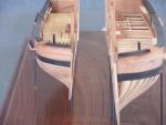
dgbot reacted to pete48 in Haven 12 1/2' by pete48 - 1" = 1' Scale - Joel White version
Here is an update on the 12 1/2 one-off, I figured out what needed to happen to make the frames work out. Starting with the 12 1/2 plans ( Herreshoff ) measuring from the waterline to the base line , I would have to lower the transom 7/16". so the slope is 7/16" to zero over 16, so this means I would have to remove all the frames, I pondered this since discovering the problem, Today, I decided to remove the frames, this proved to be difficult and I went thru a lot of blades. I will say this Titebond 3 is some really strong stuff, and does not come apart without taking the majority of the wood with it. I then decided that I would cut the remaining frames off at the blocks, fortunately, I was able to save the frames ( I taped them together and put them away ) I then used a framing hammer and a 1" chisel to remove the blocks, I will re-purpose the Baseboard for the Garden Eel. I can't believe that took all day. Here are the results
-
dgbot reacted to pete48 in Haven 12 1/2' by pete48 - 1" = 1' Scale - Joel White version
Hi, Cap'n'Bob, I did use The Titebond 3 on another build as the only sealant, and it worked out really well, However, I will be using West System to attach the Keel and coat the outside of the Hull.
Best Regards,
Pete
-
dgbot reacted to pete48 in Haven 12 1/2' by pete48 - 1" = 1' Scale - Joel White version
Here is an update on No. 2 the ribs are bent the Stem, Transom and Knee are made. The Keel is bent and ready to be laid. I think this keel will finish better than on No. 1 Here is where she is at
-
dgbot reacted to pete48 in Haven 12 1/2' by pete48 - 1" = 1' Scale - Joel White version
Today, I started by cutting the ribs in the bow section down to the sheer line. ( station 7 forward ) I then Brushed on Titebond 3 to the bow section and aft section behind station 19. This will seal up these 2 areas, Next I worked on the Centerboard box, first by laying it out from the plans and then getting it to the proper width, in this case it took 1/8" plus 3/32" bass wood, I then decided to finish it off with Teak ( thank you Michael ) I then dry fit it into position, I decided to make a new station 7 bulkhead and applied Teak and dry fit it as well.( I will add Teak to the station 19 bulkhead as well) Next will be to Install the floor framing and add the rear deck beams. Here are the results
-
dgbot reacted to pete48 in Haven 12 1/2' by pete48 - 1" = 1' Scale - Joel White version
Today, I decided that I would make her a Sailing version, I started by laying out the Keel. First I took the lines drawing and transferred the Keel to 1/ 16" basswood, cut out the parts needed and glued up the Keel. I then faired outside of the Keel. I now had an empty shell, I then raided my Tackle box grabbed a few bags of sinkers and cut the lead to fit in the shell, To seal it all up, I used Titebond 3 wood glue. ( Water proof ) and Like I said to John, I will make a centerboard in the down position out of 1/8" steel, and that should give me the weight needed. Here are the results
-
dgbot reacted to pete48 in Haven 12 1/2' by pete48 - 1" = 1' Scale - Joel White version
Hello, John, Originally, that is what I thought, My problem is the Ballast, ( not having enough ) I encountered the same problem on the 1st Buzzards Bay 14, and ended up filling the bilge with the weight needed, On this one, I am going to make the center board out of 1/8" steel in the down position, I think that this plus the Keel will give me the ballast needed, without cluttering up the Bilge
Best Regards,
Pete
-
dgbot reacted to pete48 in Haven 12 1/2' by pete48 - 1" = 1' Scale - Joel White version
Thank You, Patrick, I am building her in the same manner as the Full size boat, I am still not sure how the Keel is going to work out, I think once I've got it figured out, I will determine whether to Sail her or not. I am leaning toward Sailing her. ( Pond style no radio )
Best Regards,
Pete
-
dgbot reacted to pete48 in Haven 12 1/2' by pete48 - 1" = 1' Scale - Joel White version
Today, I started by Bending in the final rib at the stern knee, ( port and starboard ) Next, I installed the deck clamps, and trimmed the ribs down, they will still need to be sanded. I then turned my attention to the bow section deck clamps ( forward of station 7 ) these sit below the sheer line, so that they pick up the load of the deck beams, wich were cut and installed,after the Breast hook was installed. The bow section is roughed in along with the Cockpit bulkheads. ( wich have not been glued in ) Now it's decision time, If I make her a Sailing version, I will make a steel centerboard wich will be fixed in the down position. If I make her Static, then I will make the Centerboard as per plan. That being said, over the past few days( while waiting for paint to dry/wood soaking ) I re worked the molds and started bending the ribs over the molds. Next will be to finish the floor framing, and finish the bulkheads. Here are the Results
-
dgbot reacted to GLakie in Sovereign of The Seas by SawdustDave - FINISHED
Wow that turned out excellent Dave! You did a beautiful job!
-
dgbot reacted to SawdustDave in Sovereign of The Seas by SawdustDave - FINISHED
And here's the result of the re-pouring of the mold last night.
The new mold was absolutely flawless.... which gave me a really fine reproduction part.
On to the paint booth.