


mbp521
-
Posts
1,003 -
Joined
-
Last visited
Content Type
Profiles
Forums
Gallery
Events
Everything posted by mbp521
-

Barncave Shipyard by mbp521 - Scale 1:1
mbp521 replied to mbp521's topic in Non-ship/categorised builds
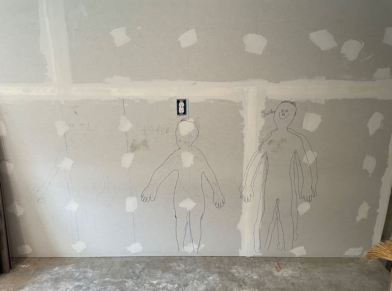
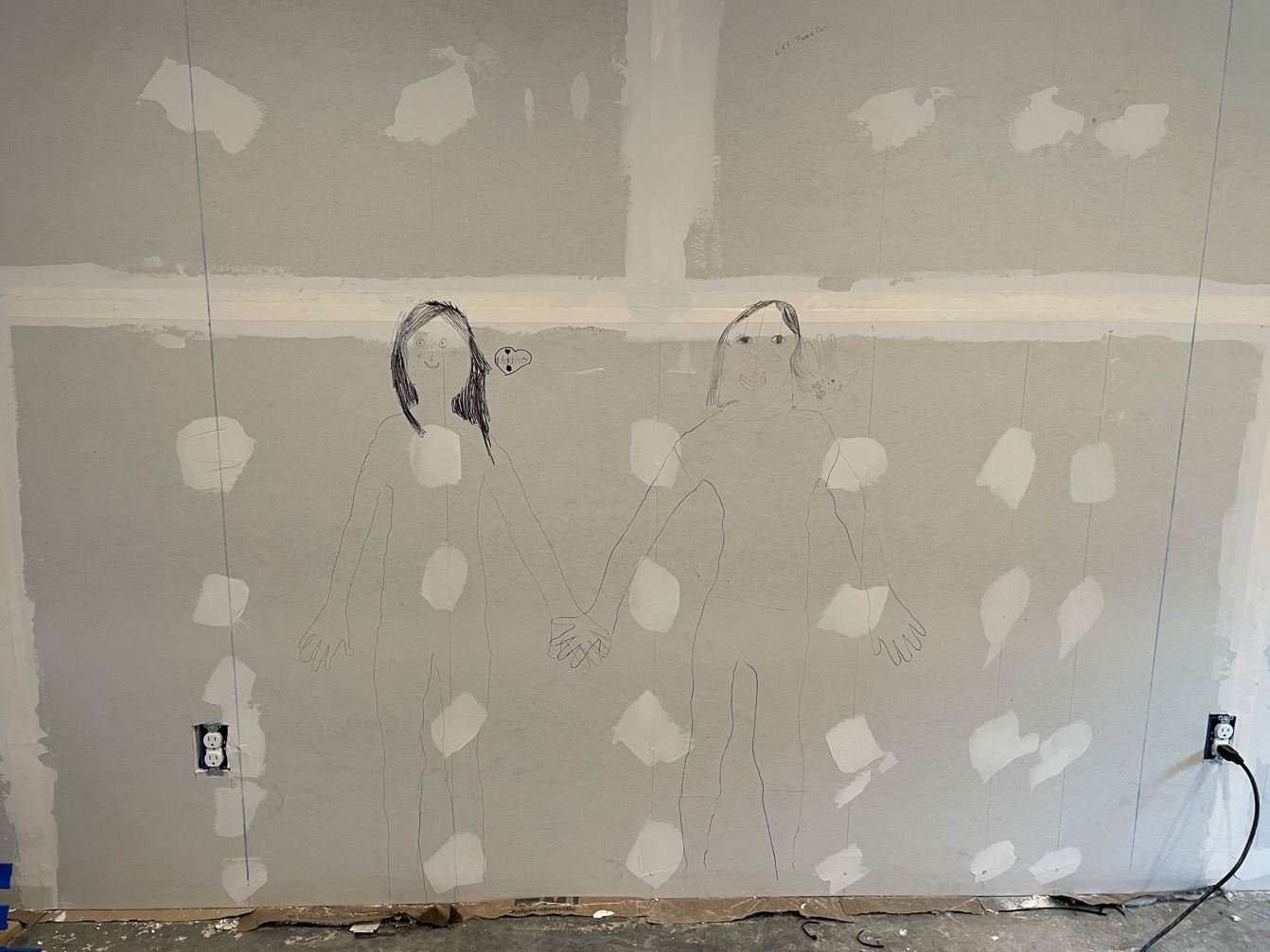
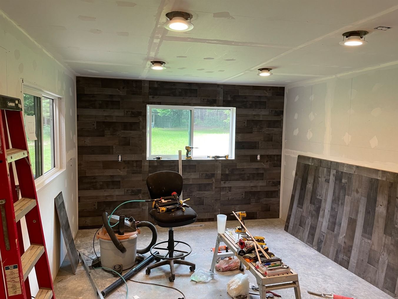
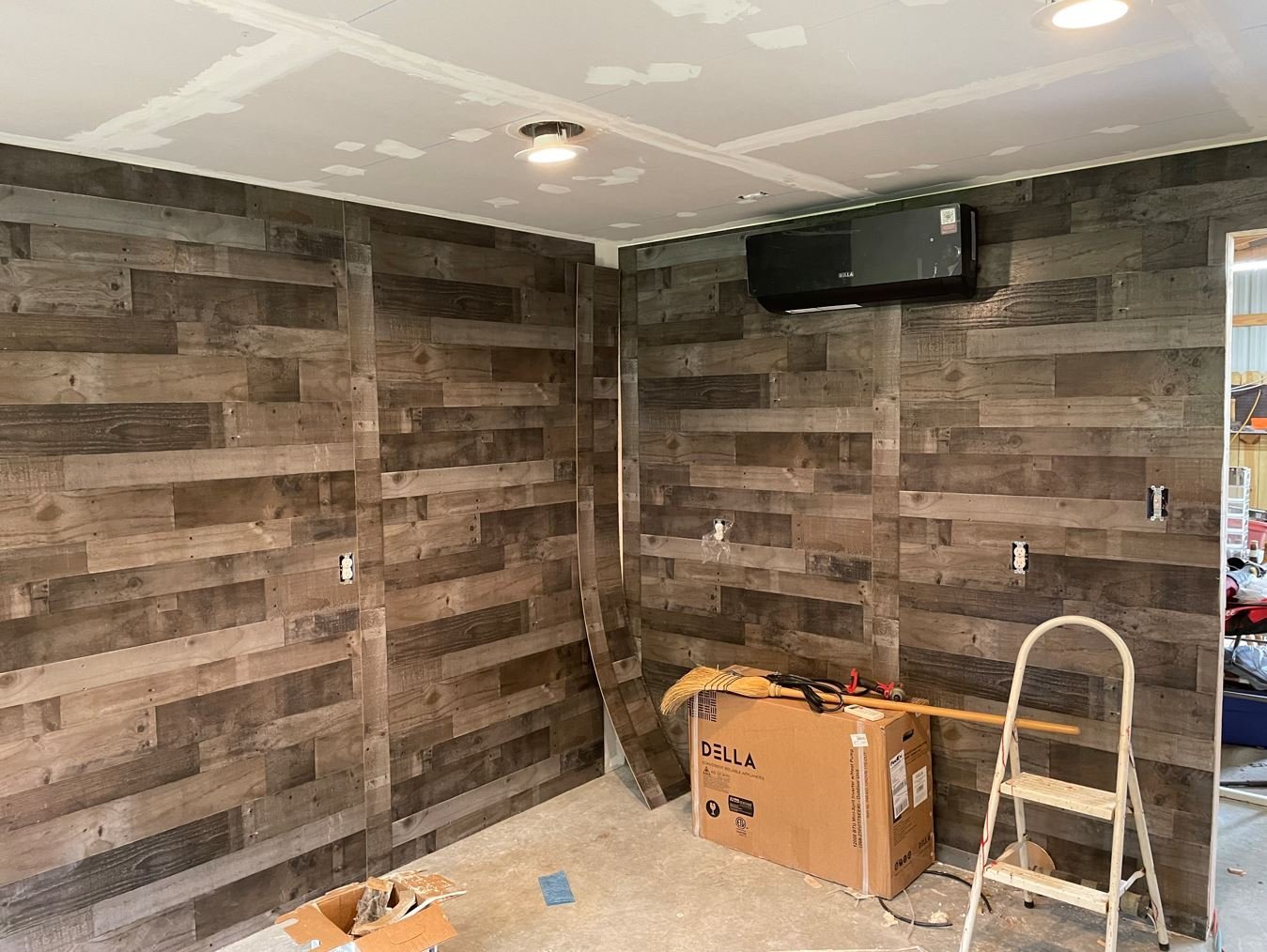
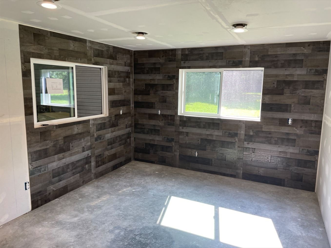
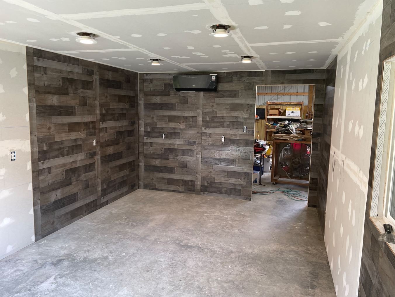
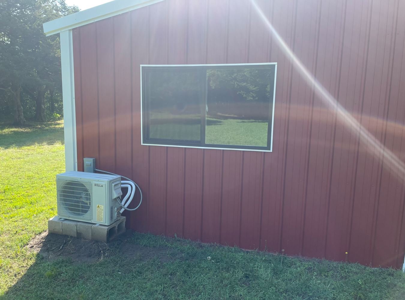
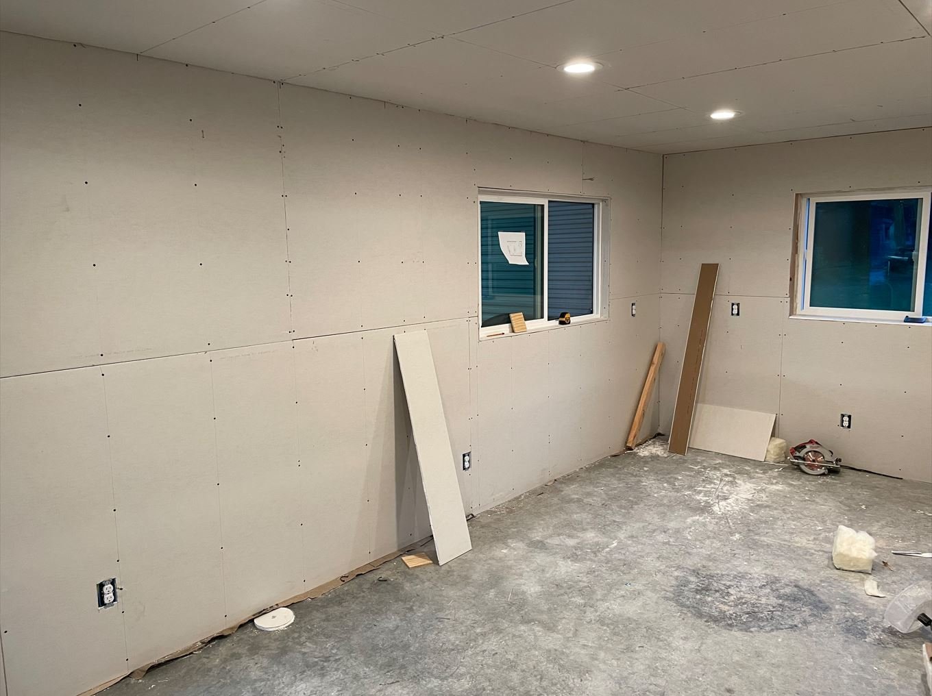
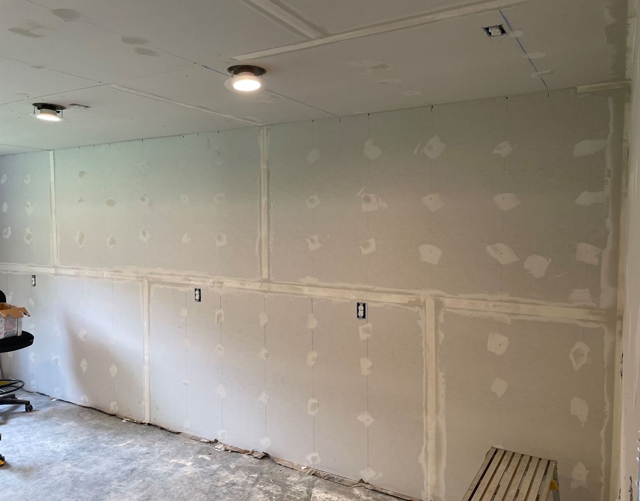
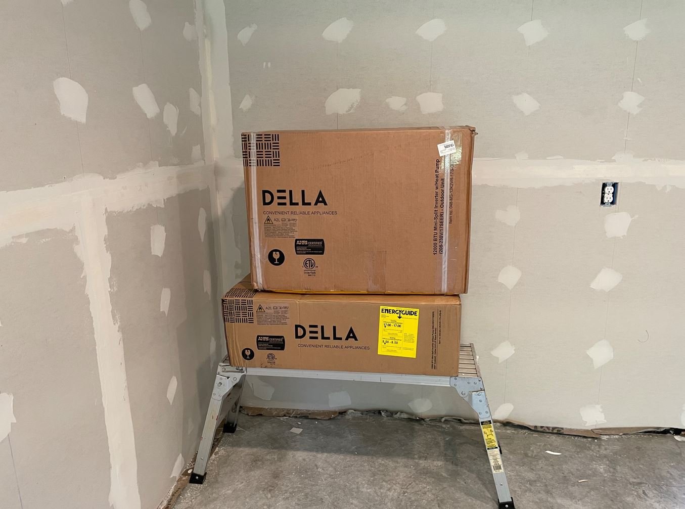
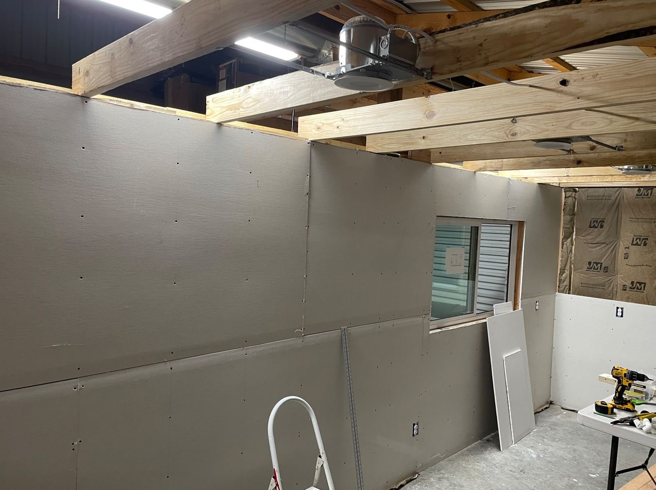
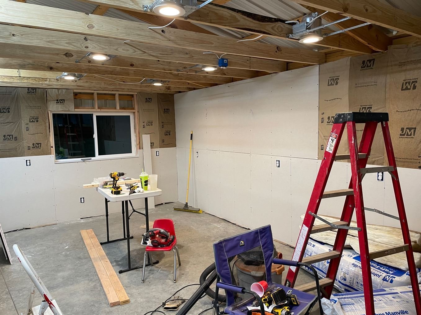
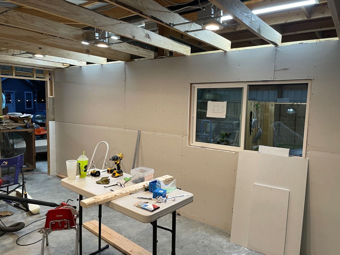
Moving right along, Day 14: The kids and grandkids came over and my son's once again graciously volunteered to help install the mini-split (it's amazing how easily they can be bribed with food). As our kids were growing up, we did what a lot of parents did and kept track of their growth by measuring them on the wall and marking it down. I do the same with the grands, they each have a column in the barn that we keep record of them on. Well just before we started working we decided to update each kids height since they were all there. It was while we were doing this that my kiddos reminded me of something that we did when they were young. I was remodeling our house years ago and we traced each of our kids outlines on one of the walls of the house. The wall was eventually paneled over, but if anyone were to remove the paneling, they would see our kiddos silhouettes behind it. I though why not continue the tradition and trace the grands. So we did. I think my kids had just as much fun reminiscing of their time doing this as I had watching them trace their kids. The granddaughters: The grandsons: After that it was time to move on with the mini-split installation. Initially I was going to use wood flooring for the walls, until I found that the only color that I really liked was way too thick and even more expensive. So I did some searching on the internet and found wood paneling that was close enough to the scheme that I was looking for and a lot cheaper. So I went with the paneling instead. The first wall up was the one with the indoor half of the mini-split. I didn't want to cut in the paneling around it so I threw it up first and we installed the indoor unit. Now the outdoor unit installed. Day 15: With day 14 spent installing the mini-split and again my hired help gone, it was back to working on my own. The taping and mudding was completed (we had to leave part of the wall and ceiling open to run the copper and control wires for the mini-split) and I was able to get all of the paneling up. Once again I miscalculated. One sheet short. Oh well, there are plenty of other things that can be done in the meantime until I can get back into town to pick up an additional sheet. Day 16: With all the paneling in place, It was time to clean up this mess. I was tired of tripping over boxes, ladders and other assorted items that were in the way. So the floors were swept and vacuumed and the walls were wiped down. Looks like the floors are going to need to be cleaned up a bit more before the flooring goes in though. I may have to invest in a cheap mop, not sure it will be of much use once I get done with it. My plan is to put up beadboard behind the built ins, that is the reason for the gaps in the paneling. The remaining paneling will be installed between the workbench and the upper cabinets. Some time today, my ceiling tiles should be delivered, and I will work on getting those installed. I also need to start working on the door so I can close this room off and make good use of the AC, the days are starting to get a tad bit warm. For now, this is as much progress as I have been able to make. Thanks again for stopping by. -Brian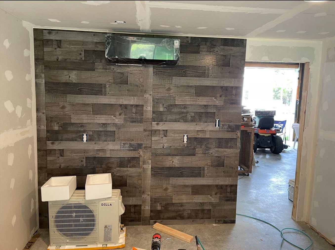
- 70 replies
-
- 13
-

-
Barncave Shipyard by mbp521 - Scale 1:1
mbp521 replied to mbp521's topic in Non-ship/categorised builds
Roger, since we live in the country and this room is out in our barn, I wanted to make sure that I could keep out as much of the creepy-crawly critters as I could. The wood sheathing has some gaps in it, so they can get in through there, but the taping and mudding should help seal some of it off. I also spray foamed some of the bigger gaps and caulked under the toe boards as an extra precaution to help protect the exterior walls. It may be a little extreme, but I wanted to do it right. -Brian- 70 replies
-
- 11
-
-
Barncave Shipyard by mbp521 - Scale 1:1
mbp521 replied to mbp521's topic in Non-ship/categorised builds
Hey Bob, a mini-split is basically a scaled down version of a home heat pump unit. There is an outdoor condenser with the cooling/heating unit inside the room. The two units are connected by copper tubing and control wires. This particular unit is a 1 ton designed to climate control about 550sq ft. More than enough to keep my little 240sq ft comfortable. It is also a lot more energy efficient than a standard window unit. Nice part about it is it has a feature where I can control it from my cell phone so I can warm it up or cool it down before leaving the house. 😁 Gotta love that modern technology. -Brian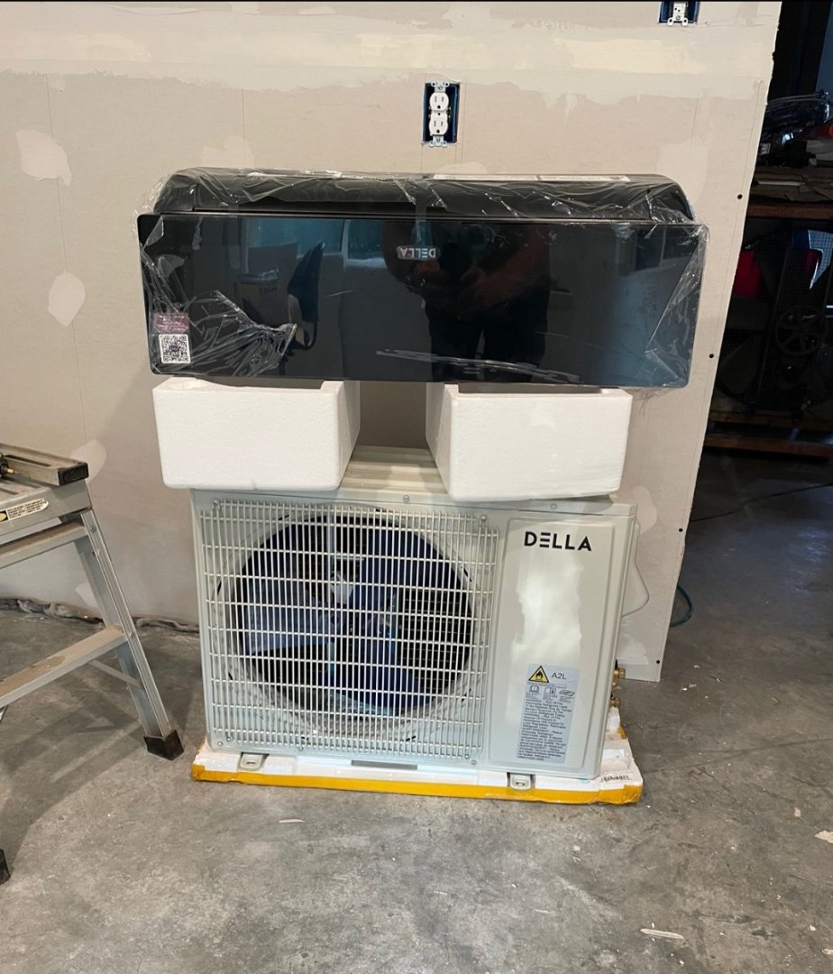
- 70 replies
-
- 12
-
-

-
Barncave Shipyard by mbp521 - Scale 1:1
mbp521 replied to mbp521's topic in Non-ship/categorised builds
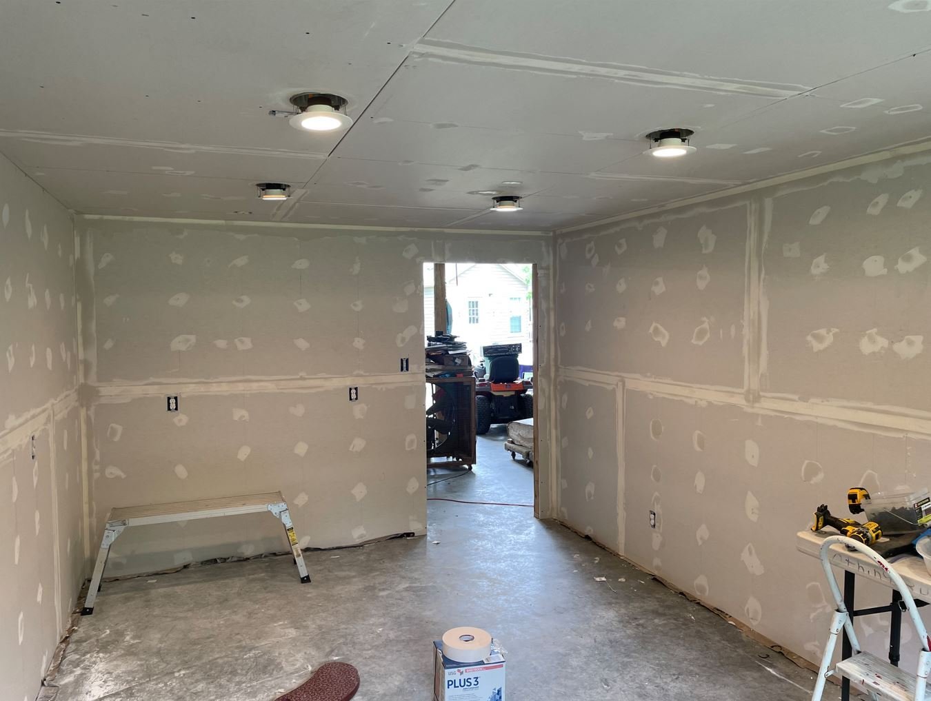
Time for another update. Day 11: With the extremely appreciative help from my boys we were able to get all of the ceiling drywall put up. It took the better part of the day, but it is done. I was even able to talk them into putting up the ceiling insulation as well. I guess I raised them right. Day 12: Back to working solo. Today was taping and bedding. Another slow process. I tried as best as possible to minimize the amount of seams in the drywall, but there was still al lot to contend with. I have a few more seams on the ceiling to finish up with, the overhead work sure takes it's toll on the shoulders and neck. Day 13: As I was typing this, the delivery truck showed up with my mini-split unit. Just in time, the days are really starting to warm up. Looking forward to this nice long weekend coming up to finish the taping and getting the AC installed. I might even be able to start detailing the walls. Thanks for stopping by. -Brian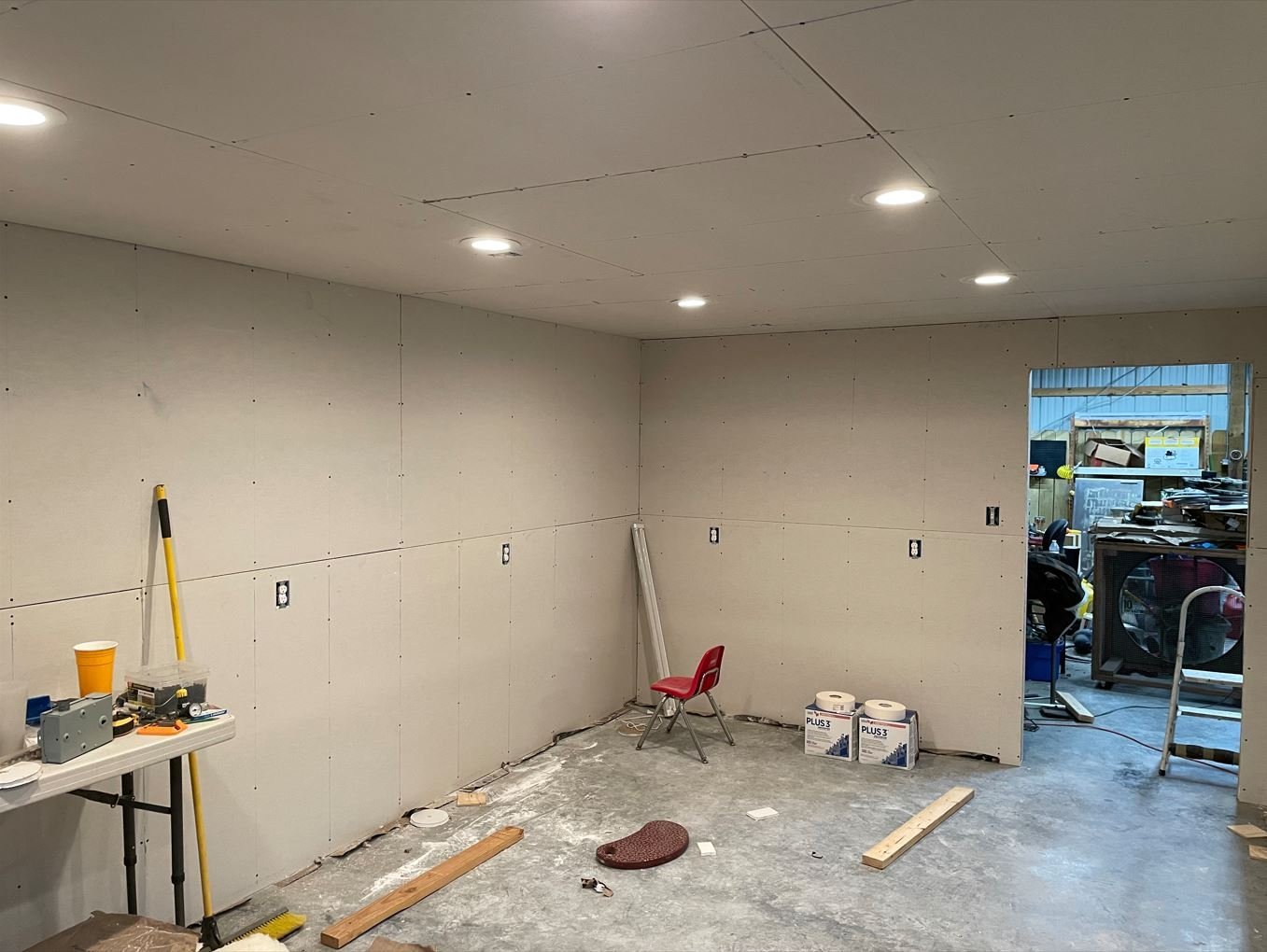
- 70 replies
-
- 15
-
-
USS Cairo by Zetec - FINISHED - 1/50 scale
mbp521 replied to Zetec's topic in - Build logs for subjects built 1851 - 1900
Very nice work John! I wish that I had done my hatches this way instead of planking then cutting them out. I ran into several issues where there was no support under them when they were cut out and had to "beef up" the openings from underneath to get the hatches to sit right. -Brian -
Barncave Shipyard by mbp521 - Scale 1:1
mbp521 replied to mbp521's topic in Non-ship/categorised builds
Thank you Brad for the useful information. I definitely try to avoid the sparky as much as possible! At the moment I don't have any good pictures of my reloading setup, and to be honest, with all the construction I have going on I am ashamed as to how much disarray everything is in. So much so that I really don't know if I could take a decent picture of it right now. However, it can be seen in my first post of this log in the fifth picture. It is the brown bench that has the blue tarp on the front of it. The bench is currently mobile and is where I do most of my reloading, but it will become a permanent fixture once the shipyard is complete. Basically meaning that I will be taking the wheels off of it . I also plan to remove the tarp and build doors on it (because why not, it's not like it's already heavy enough). The bench itself is 7.5' long 36" high and 24" deep, made from 2x4's & 3/4"plwood, with a Formica top and it is a beast. I bought it from a guy here locally off Marketplace for $50. It took three of us to load it in my truck, but I just couldn't pass it up. I currently use a Hornady AP setup, that I absolutely love, for my everyday plinking rounds (.45 acp, 9mm, .556, 300 AAC). Before I was using a Dillon 650 setup, but I was constantly having issues with it (I bough it used) so I swapped to the Hornady a few years ago and I have been going with it ever since. For my precision rounds (6.5 CM, 7mm mag & .308) I use an old Lyman Turret press that I have setup to function as a single stage and just rotate the head to whatever caliber I am reloading at the time. All of my precision rounds are primed and loaded by hand and the powder measured with an RCBS Charge Master dispenser. I do have a plywood cabinet that I store all my powder and primers in. It may make it to the new room and it may not. I am still hashing out those details as I go. Since the humidity doesn't get that bad here in North Texas I do believe that my mini-split will do the job needed to keep everything in good shape, but I will keep a close eye on it just in case. Especially since I will also have several of my previous wooden builds in the room along with the reloading supplies. Stay tuned, hopefully I can get some of my mess cleaned up enough to where I can take a picture of my setup and get it posted. -Brian -
Barncave Shipyard by mbp521 - Scale 1:1
mbp521 replied to mbp521's topic in Non-ship/categorised builds
Thank you Keith. I do plan on taping and bedding myself, that's the easy part, it's the floating and feathering all the seams that is a pain. Fortunately I plan on covering the walls with wood planks so I won't have to deal with all the sanding and dust floating creates. No messy texturing either. -Brian -
Barncave Shipyard by mbp521 - Scale 1:1
mbp521 replied to mbp521's topic in Non-ship/categorised builds
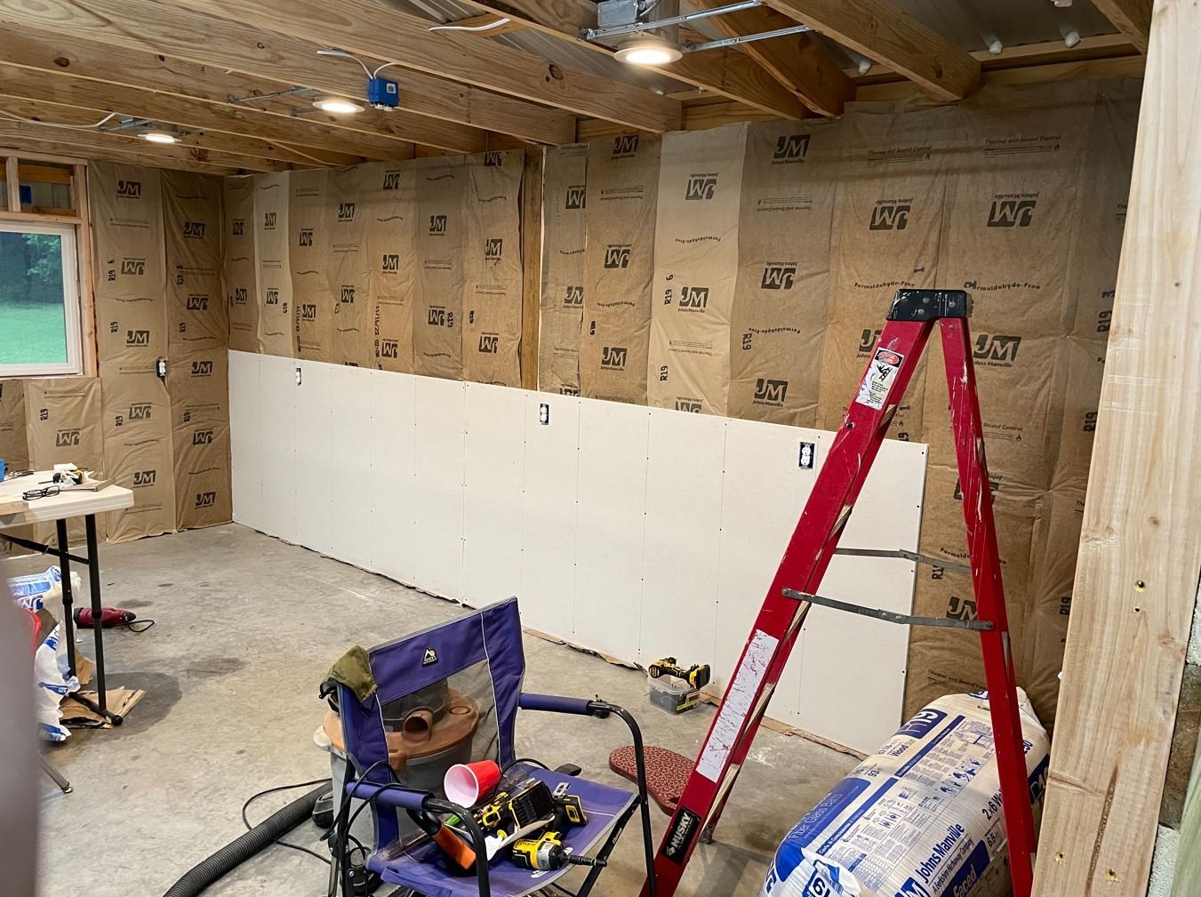
Back with more. Day seven: I finally finished up with the itchy stuff. At least for the walls. Long sleeves, long pants, goggles and a mask was still not able to keep those tiny fibers of glass from making me itch. Maybe it was just a mental thing, but I'm glad to be done with that part. Day 8 -10: Time for the drywall. This is a slow process when you are hanging each sheet by yourself. Took me a few days to get this done. Thankfully my sons are coming over this weekend to help with the ceiling drywall. Once we get the ceiling completed, it will really start looking like a room. I am hoping that I can con, swindle, bribe, or guilt my boys into putting the insulation on top of the ceiling so I can avoid the itch monster again. Also, my mini-split unit should be arriving some time next week. Once I get that installed It should make for a more comfortable working environment. Well that is all for now. I'll post more after this weekends progress. Time to go and get some of this mess cleaned up. -Brian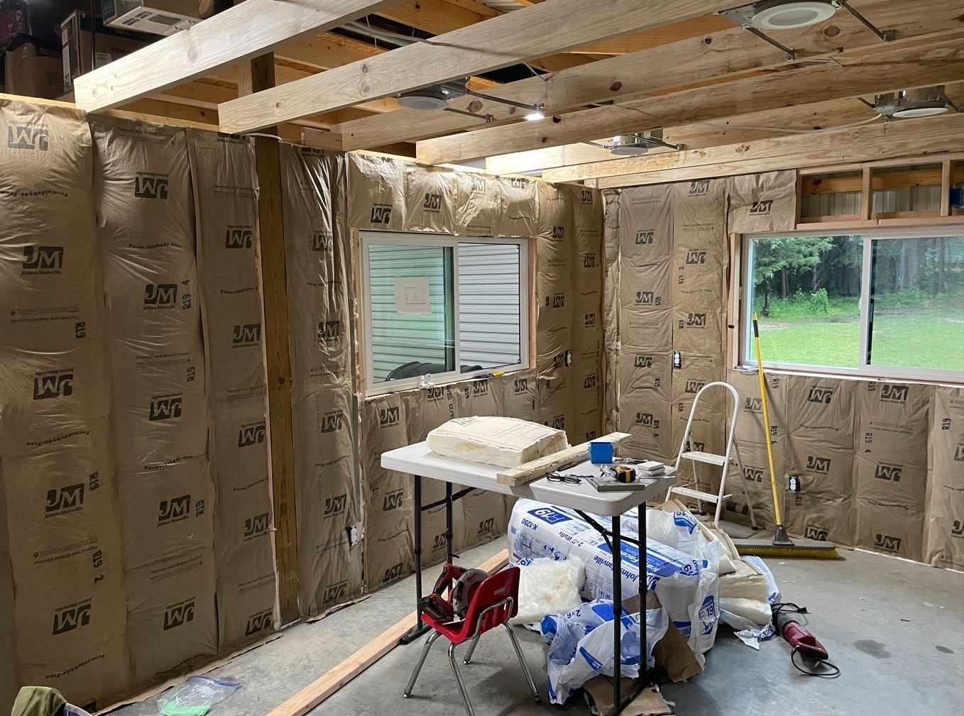
- 70 replies
-
- 16
-
-
Barncave Shipyard by mbp521 - Scale 1:1
mbp521 replied to mbp521's topic in Non-ship/categorised builds
Thank you Keith for the reminder. One thing I did incorporate into the design was wood floors. So much easier to find dropped parts. I have a feeling that once I move out of my current spot in the house, that the hundreds of tiny pieces that I offered up to the carpet Gods will miraculously turn up. As for the "where did I put that "xxxxxx" craft knife" desk, science has yet to develop a remedy for this, so even with the new room, I am doomed to forever be on the search for that elusive knife. -Brian -
You might have a bad day if you happen to pop your head out of that hatch when they were firing the Parrot. 😁 -Brian
-
Barncave Shipyard by mbp521 - Scale 1:1
mbp521 replied to mbp521's topic in Non-ship/categorised builds
Thank you Yves! I do have several kits stored away that I might be able to find room for. If I come up short on space, that’s always a good excuse to add on. 😁 -Brian- 70 replies
-
- 11
-
-

-
Barncave Shipyard by mbp521 - Scale 1:1
mbp521 replied to mbp521's topic in Non-ship/categorised builds
That is a strong possibility. She has already been out there a few times measuring for curtains. Thank goodness I have another two stalls on the other side of the barn.😁 I did forget to mention that Mark. I have a 3/4 ton mini split on order for it with a 12000 btu heater. Should be more than enough to keep me (the Admiral) climate controlled. It can get a tad bit warm in the summers and quite chilly in the winter. The mini split should take care of it and I am going all out on insulation too. -Brian -
Barncave Shipyard by mbp521 - Scale 1:1
mbp521 replied to mbp521's topic in Non-ship/categorised builds
One of the things my grandfather taught me was to never pay anyone for something you can do yourself. Words I have lived by all my life. Wait until you see what I have planned for the door. - Brian -
Barncave Shipyard by mbp521 - Scale 1:1
mbp521 replied to mbp521's topic in Non-ship/categorised builds
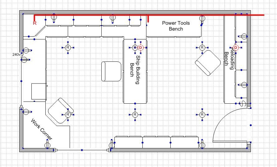
Oh most definitely Keith. I will have plenty of lighting. The can lights are just for the room itself. If you notice that on the ceiling joists there are blue boxes mounted there. These are for some 4' hanging LED light bars that I currently use in my "temporary" shipyard. Plus I will also be using the LED articulating magnifying lights that are on my bench now as well as LED light strips mounted under the shelves and upper cabinets that I will be installing. With all of the lights that I have planned, I may need sunscreen and sunglasses when I turn them all on. -Brian- 70 replies
-
- 12
-
-
-
Hi John, I do apologize for not getting back with you on the cannons, I have not been keeping up with my email like I should and missed the notification. Hopefully you were able to sort them out. The kits I used for the ships boats were the Model Shipways 5 3/16" lifeboat kits (found here: https://modelexpo-online.com/5-316-135mm-Plank-on-frame-Lifeboat-Kit_p_849.html ) I did have to lengthen the keel about an inch to get them to the right scale, but for the most part this was an easy task and they worked out fairly well. I am always happy to help out and will try to keep a closer eye on comments in my Cairo build log, but in the future if you have any questions along the way, you can also send me a private message, I might see that a little easier and respond a lot faster since MSW sends a separate email with a new topic. -Brian
-
Hey everyone, I have put the Caroline N on a temporary hiatus while I work on another project. I have finally started work on my new shipyard. I wanted to get most of this completed while the temperatures here in Texas are somewhat manageable. I have started a Shore Leave build log on it if you wanted to pop over and follow along as I progress. You can check it out here. Hopefully it won't take me too long to get the shipyard done and I'll be back to work on the Caroline N in my new digs. -Brian
-
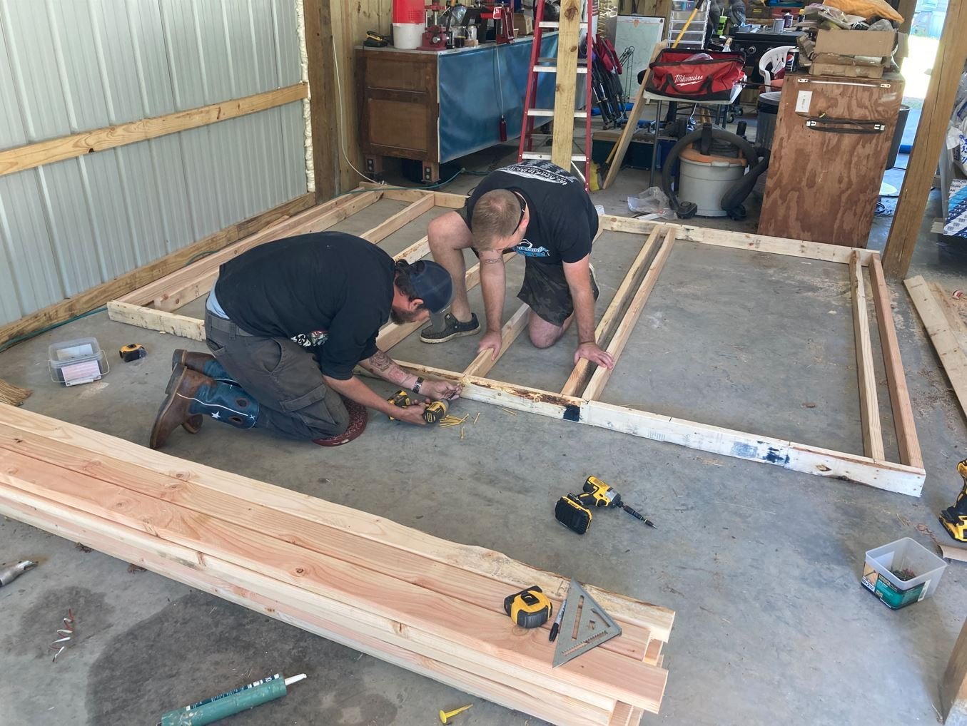
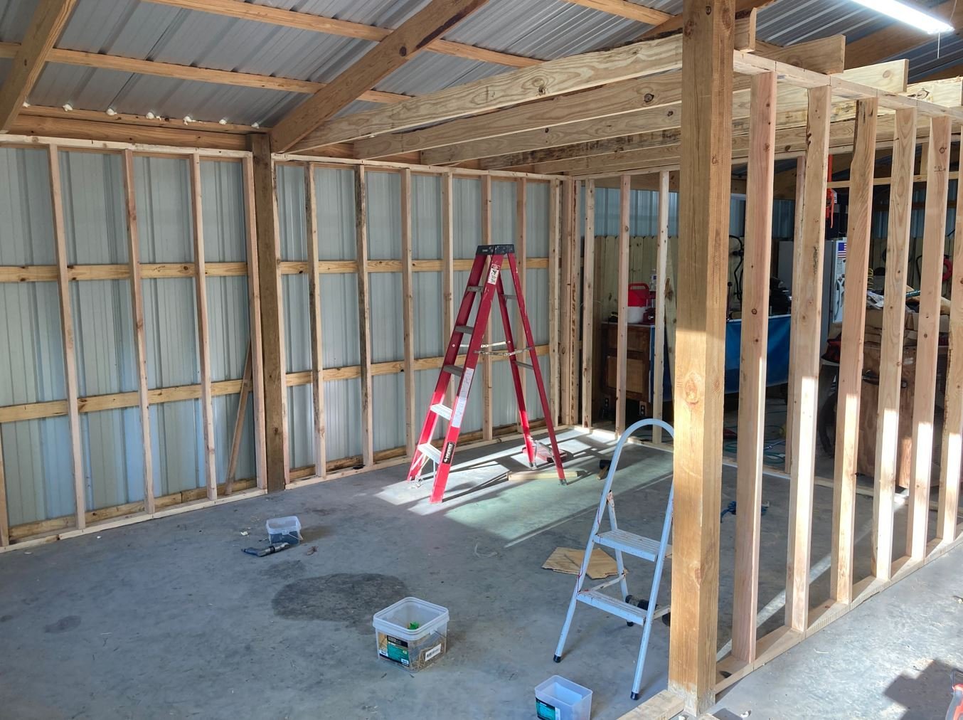
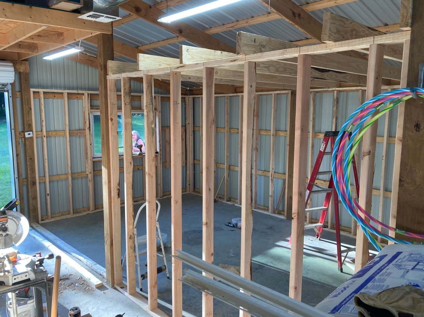
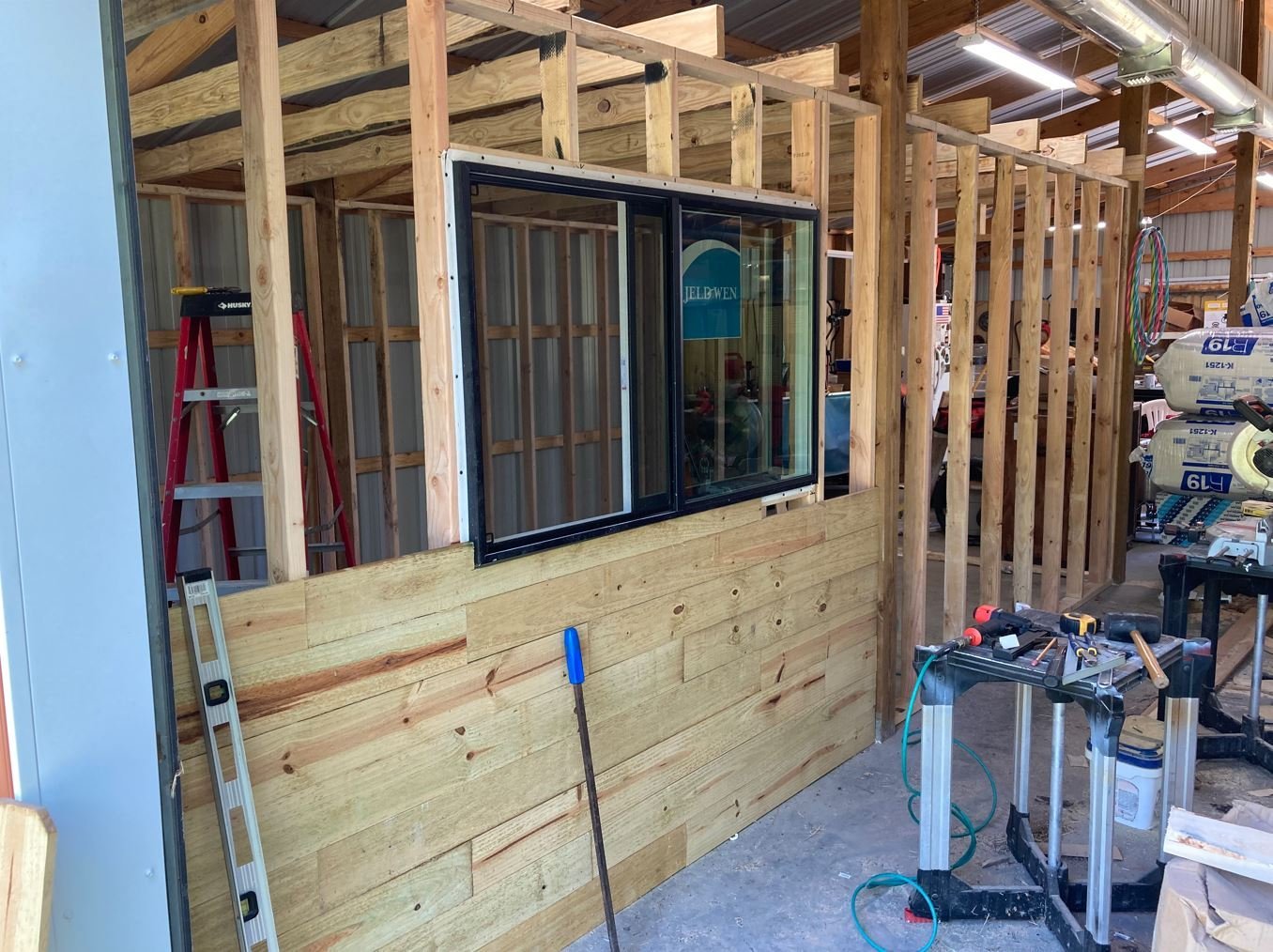
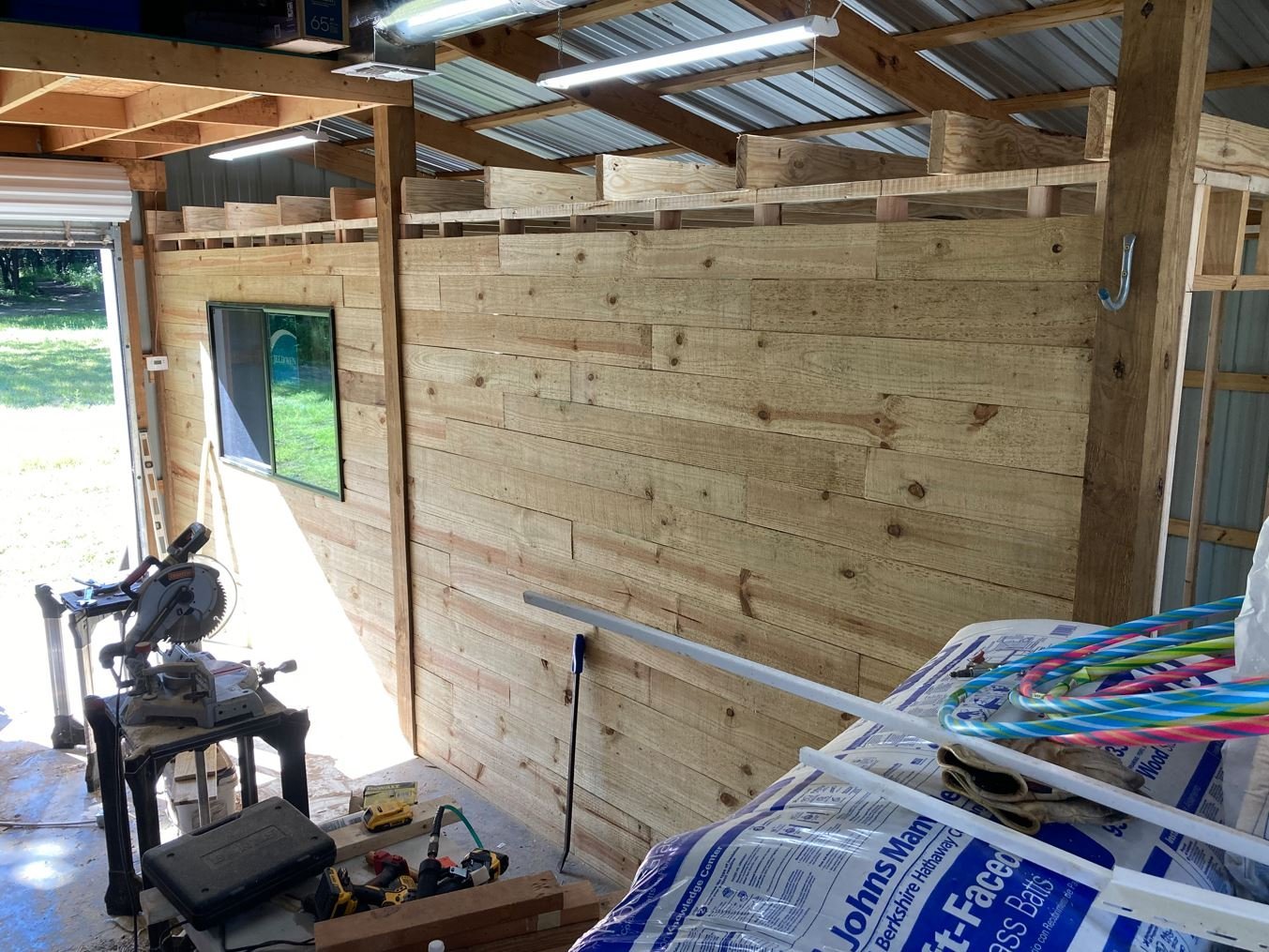
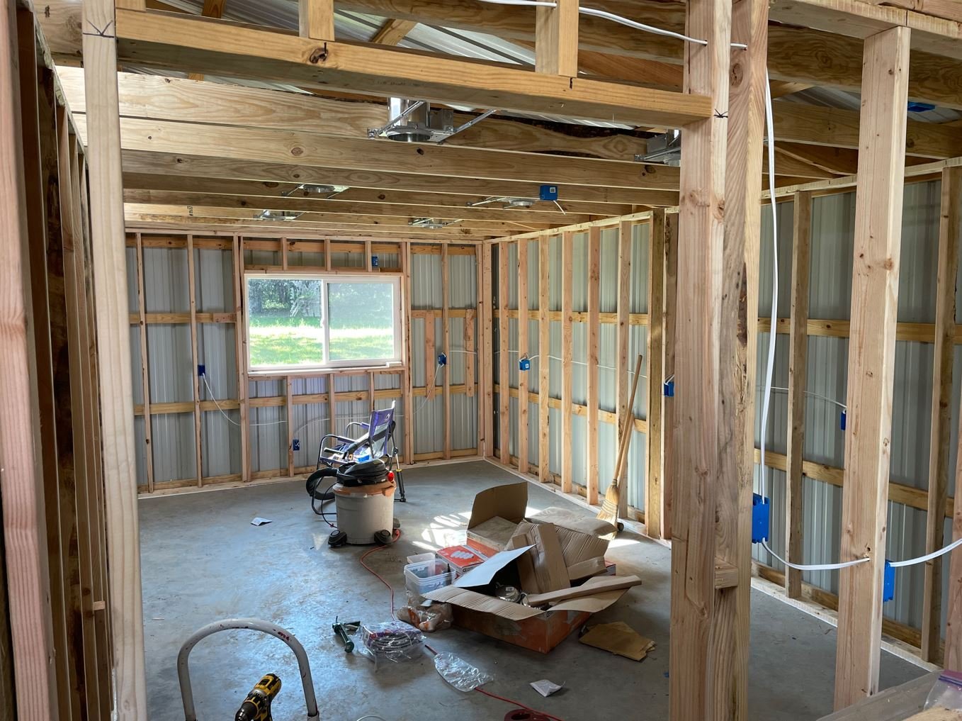
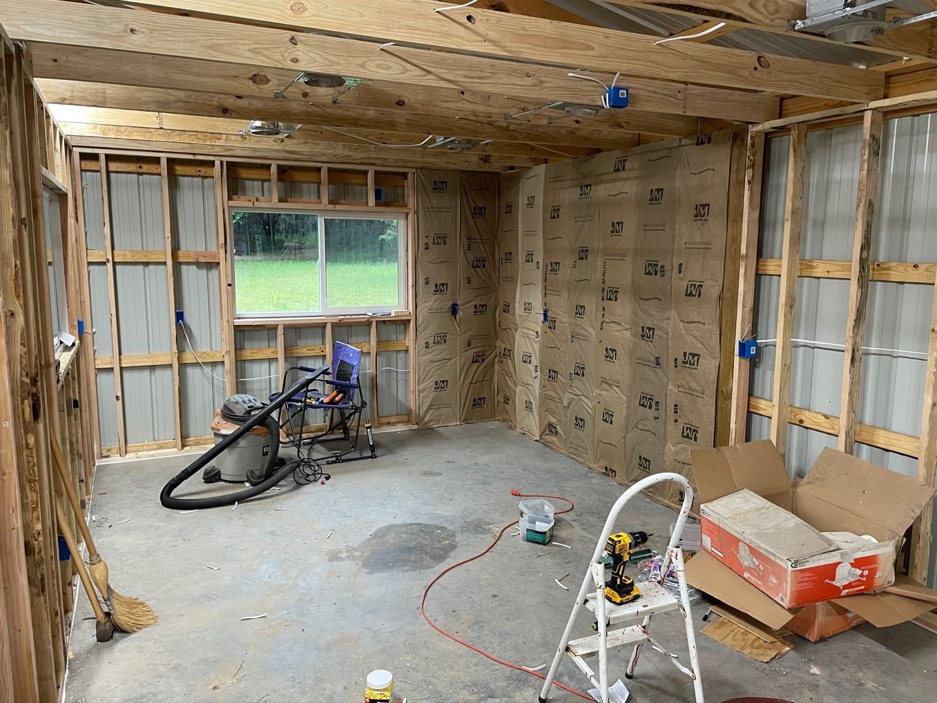
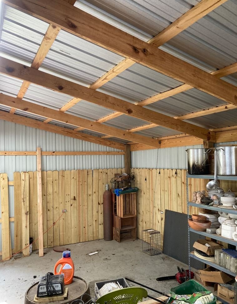
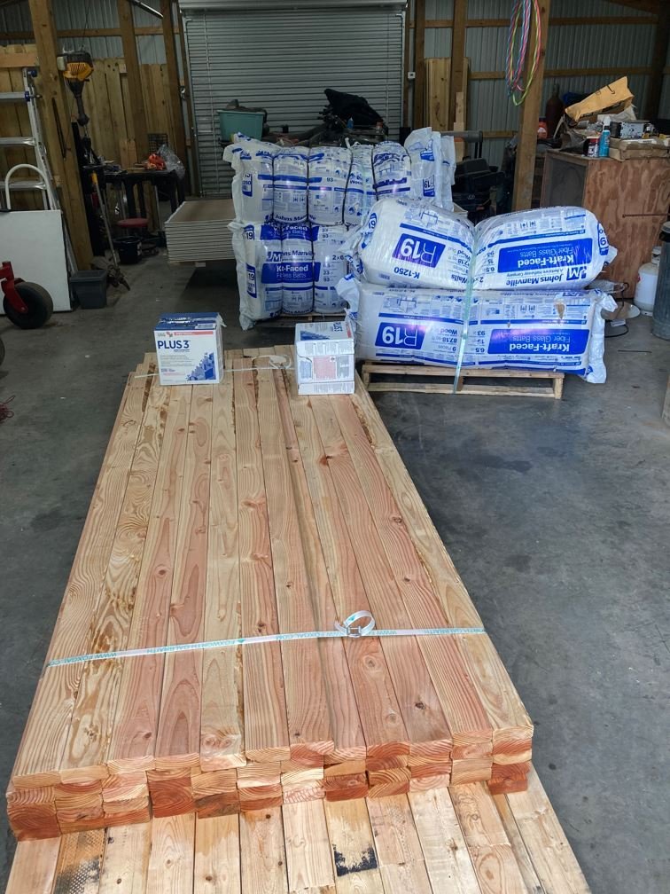
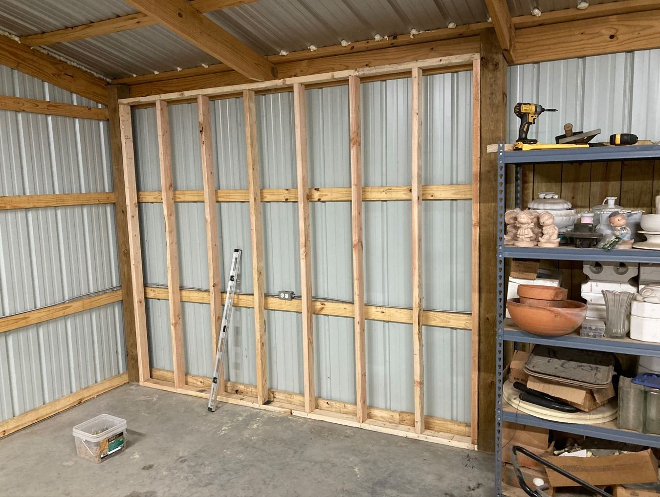
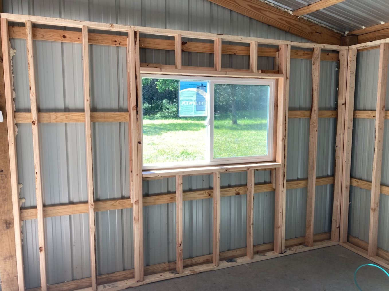
I wanted to share a project that I have been anxious to get started on for a few years now. When we built our house back in 2019, the Admiral was gracious enough to let me use one of the spare bedrooms as a shipyard in a temporary basis. Well, temporary has turned into a four year homestead. Back when I had first planned an out of the way place to move into, my initial thought was to purchase an unfinished out building and then finish it out the way I wanted. Well, not sure if you have priced any of these new out buildings, but they are ridiculously high, at least around here they are. A nice 20'x12' unfinished wood framed storage shed will set you back about $10K to 15K. Way to rich for my blood. I even looked at used ones, which are cheaper, until I pay someone to move it for me. So I decided to utilize a 12'x20' back corner of our barn. This was agreed upon with the Admiral and so plans were finalized and materials were priced and budgeted. Unfortunately, right after the pricing was done, we had a freak storm roll through and dumped 8" of rain on us in 5 hours. This caused the creek that runs through our property to flood and wash all the leaves, branches and other debris up against the fences and rip them all out of the ground. Well, the shipyard funding had to be used to replace about 400' of fencing, posts and toprails. Then Covid hit and lumber prices skyrockets and again the shipyard was put on hold. Well since that time I have finished up an a couple of builds and found myself complacent in my temporary(permanent) home. But now with lumber prices finally back down to a somewhat manageable cost and being inspired by other land based projects, one in particular @Cathead Outdoor kitchen build has got me chomping at the bit to get off my backside and get this done. So I have put my Caroline N project on a temporary hold while I spend time out in the barn, before the Texas heat kicks in, realizing my plans for permanent shipyard. So without further ado, here we go. This is the planned corner of the barn where the shipyard will be. Plans that I drew up back during the initial planning stage. Day 1, the materials have arrived. Of course it rained the day before delivery, making things nice and muddy for the delivery driver. The forklift managed to dig some nice ruts in the ground, but the driver was able to get everything unloaded. Now I have a side project of filling in and smoothing out all the ruts and re-growing the grass. But anyway, the materials made it so time to get started. Day 2: Moving all the junk that has accumulated in the corner out and putting up the first wall. As you can see in the below picture, I was so anxious to get started I didn't take the time to get everything out of the way yet. Day three: I bribed my sons and son in law with beer and food to come give me a hand getting the walls up. Cheap labor but very helpful. Still on day three, more of the wall frames going up. Day four: With my labor team exhausted, it was up to me to trudge on. Now that I had the framing done, I was able to work on the outside walls of the shipyard. I figured what better way to wall in a shipyard than with shiplap. Day five. Electrical work. Didn't have a lot of time this afternoon to do much, but was able to get most of the electrical wiring and boxes done and the recessed lighting installed. Day six: Now to the real fun, fiberglass insulation. Even this picture makes me itch. So I gear up in an old flight suit, a throwback from my Air Force days of which I can't believe I can still fit in, and start hanging insulation. That is as far as I have gotten for this week. More to come as I progress. -Brian
- 70 replies
-
- 23
-
-
-
Glad to see you back at it John. Everything is looking good. Those battens are certainly tedious work, Are you planning to do any interior details on the pilot house? -Brian
- 158 replies
-
- 1
-
-
- chaperon
- Model Shipways
- (and 1 more)
-
Still loving the updates Tim. Beautiful work as always. Glad to see that some of my research matches up with your groups on the launches. -Brian
-
Too funny Keith! Without getting too political here, I would, but I'm too honest. 😁 -Brian
-
Timber-framed outdoor kitchen - Cathead - 1:1 scale
mbp521 replied to Cathead's topic in Non-ship/categorised builds
Coming along nicely Eric. Seeing this reminds me that I really need to get started building my shipyard in the barn. I have put it off for way too long. Maybe following your kitchen progress will inspire me to get moving on it. -Brian -
Thank you Keith. Not sure what is up with Mother Nature this year, but she is definitely on the warpath. Our damage was insignificant compared to what the South and Midwest has been dealing with, as well as the wintry stuff you guys up north have been getting. I don’t think it will be as much of an issue on the bottom, as it will be with the sides. Since these will be more visible I want to focus more attention on the plates there. At first I had thought about that too, but there were a couple of the bulkheads that I didn’t quite measure correctly and they came up a little short to get the hull contour right. I guess I could build them up a bit and go with the card stock. I’ll give it some thought before diving headlong into the filler. -Brian
-
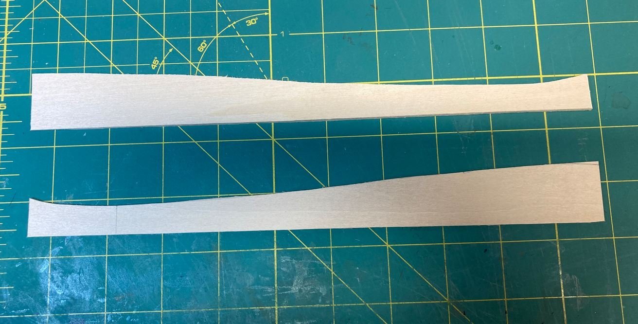
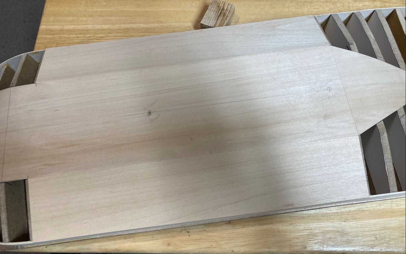
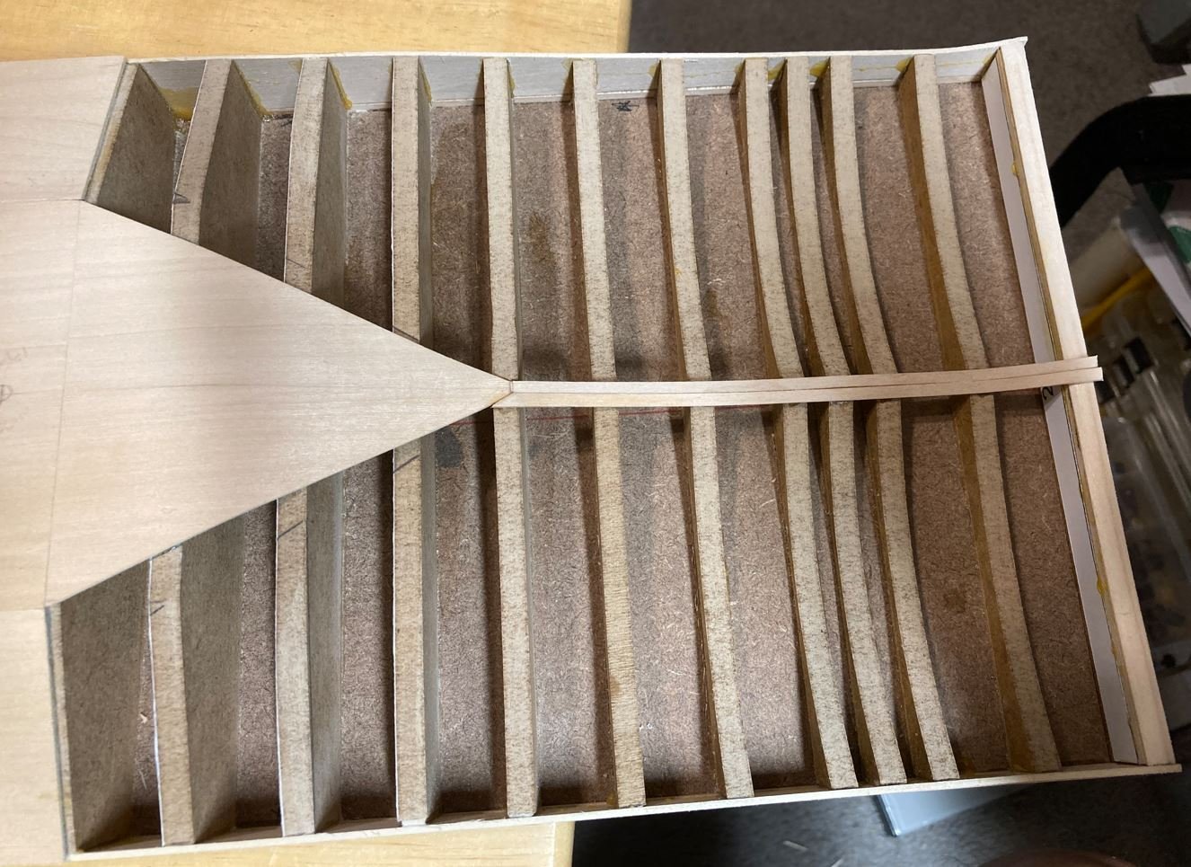
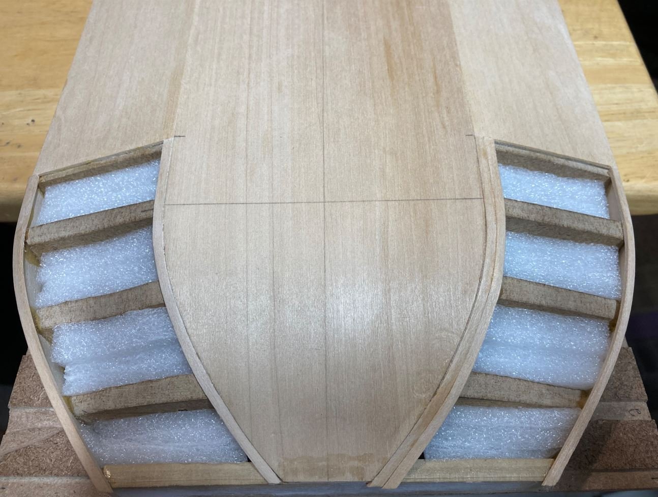
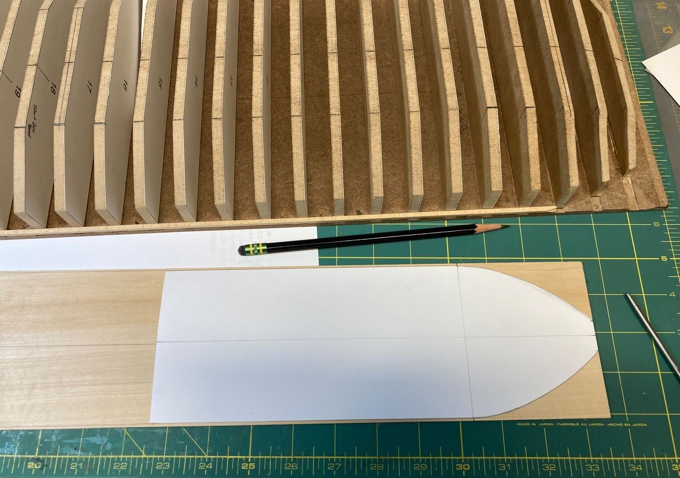
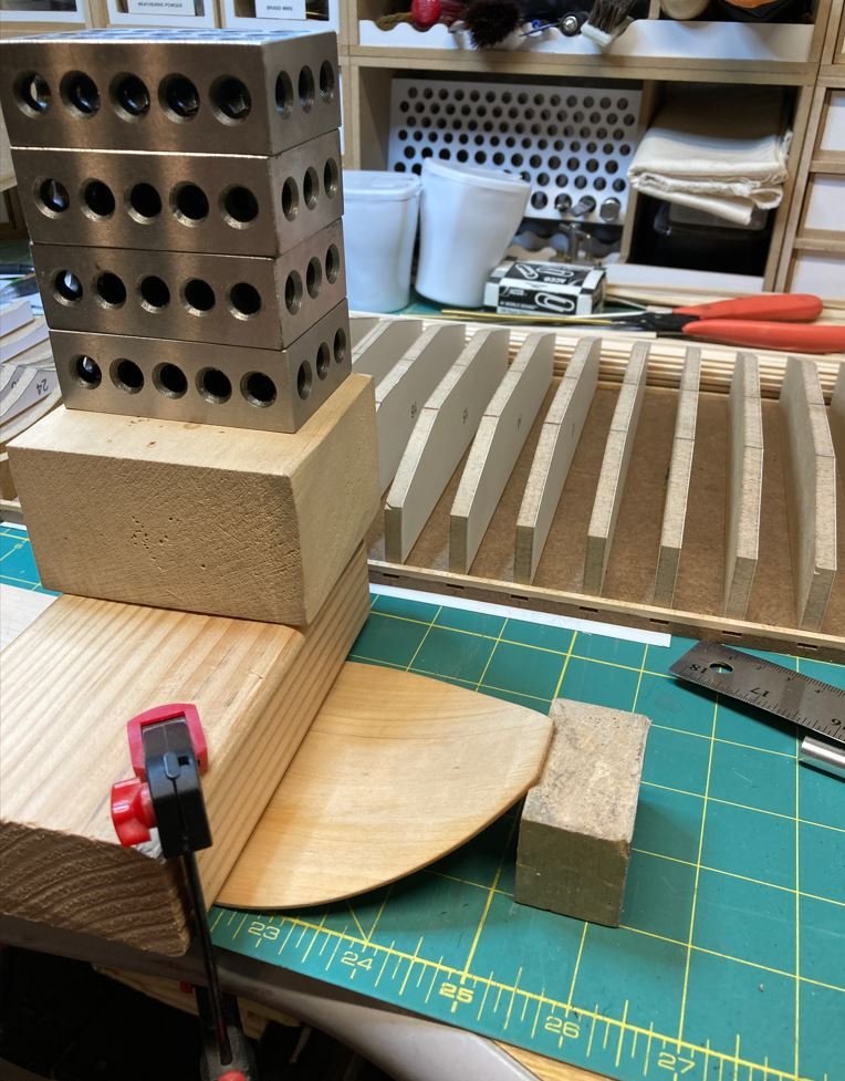
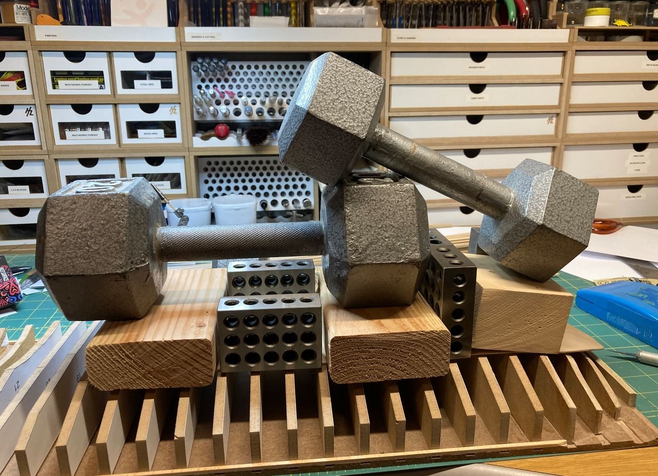
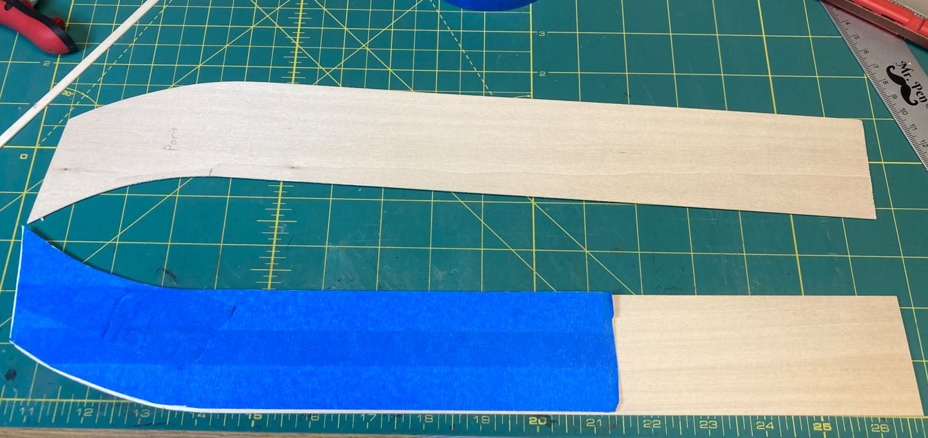
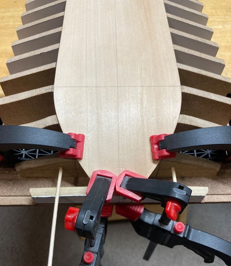
Hello again everyone, It has been a while since I have been able to get any work done, March was a very busy month. It started off with attending a cousin's wedding in South Louisiana, followed by a couple of rounds of severe storms that knocked down several trees on the property. Unfortunately these trees fell across our fencing used to contain our farm animals, so along with having to play lumberjack, we were also having to play cowboys and round up the herd. So fence repairs took some time to get done, but we managed to get them all repaired and the herd is now once again happy and contained. The fence work was also completed just in time for the Admiral and I to jet off on a two week vacation. Crossed another bucket list item off the list and finally visited Pearl Harbor (and some of the other parts of Hawaii). Once we got back from the trip, it was time to get back to the bench and get some work done. Well, I made a little progress the last week of March before Covid decided to rear it's ugly head and invade our house. First the Admiral came down with it and then me. So I have spent the last week and a half trying to kick this nasty bug, and I finally feel good enough to sit down and post an update. So with all that being said. here is what I was able to get done. I started working on getting the hull plated. I decided that I would go ahead and skin the hull with 1/16" basswood for now. I'm still not 100% sure of how I am going to simulate the steel plates, but I figured that I would go ahead and get the basic shape of the hull done and work on that once it was completed. The first section covered was the center keel area, since this was the easiest shape to make. I started with a cardstock cutout of the area then transcribed it to the basswood sheet. Next I soaked the forward end of the plank and shaped it to get the gentle curve of the bow. Then it was on to gluing the sheet to the hull. I wanted to make sure that I got a good bond so I used a little weight to help hold it down. Finally the front end of the sheet was glued, clamped and left to dry. While the first sheet was drying, I used the same method to cut out the side sheets. Once the first sheet was dry, I moved on to the port & starboard sides of the bow. I was struggling to get the compound curve of the sheet to lay right, so I decided to trim off the forward curve and take a different approach to it. Here are the side sheets in place. I was still struggling with how to cover the bow and stern areas. At first I was going to try planking them both with 1/16" x 3/16" basswood strips, but it just wasn't working the way I wanted it to. So I started rethinking things and decided that I am going to cheat a bit and use body filler to get the general shape. On the bow side it is not so bad, just a few foam blocks to fill in most of the void and some basswood strips on the sides to get the correct height and I should be good to go. The stern area is going to be a bit more difficult since there are numerous compounding curves to contend with. I will throw in a few filler blocks to take up some of the bigger areas, but I think this method will also work to get the general shape as well. This was as far as I got before getting sick. I'm on the mend now and hopefully within the next few days I should be able to get more done and have better progress. For now, thank you all for stopping by. -Brian
-
Tim, Thanks for posting more photos of the build. This truly makes me miss working on my Cairo. I am envious of the details you guys have put into this model. If these pictures are from three years ago, I can only imagine the progress that has been made since. Looking forward to the next installment. Keep them coming. -Brian

