


Overworked724
-
Posts
1,218 -
Joined
-
Last visited
Content Type
Profiles
Forums
Gallery
Events
Posts posted by Overworked724
-
-
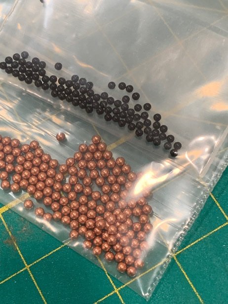
P&G’s are tucked in for later…even have a sneaky and easy way to mount them without (knock wood) causing too much damage to the copper once applied.
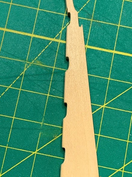
Last thing I wanted to do was prep the false keel. Since the mounting screws go up through the keelson, making the false keel in one piece is possible but tricky. Decided to break it up into sections.
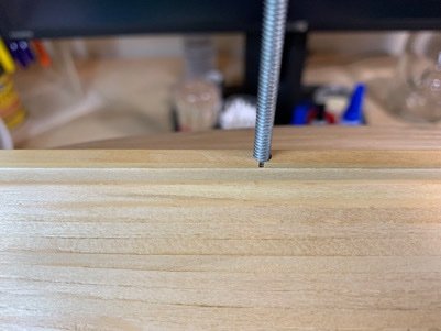
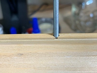
The gaps at the mounting screws will be cleanly hidden by the pedestal mounts. Again…just didn’t want to overthink this one.
Moving on….
-
-
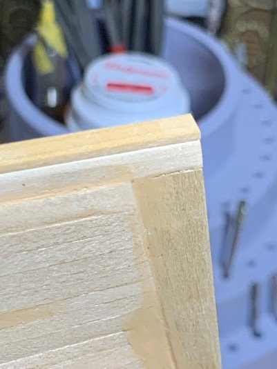
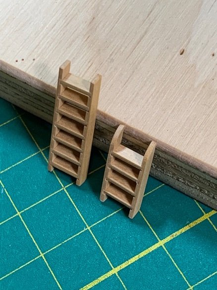
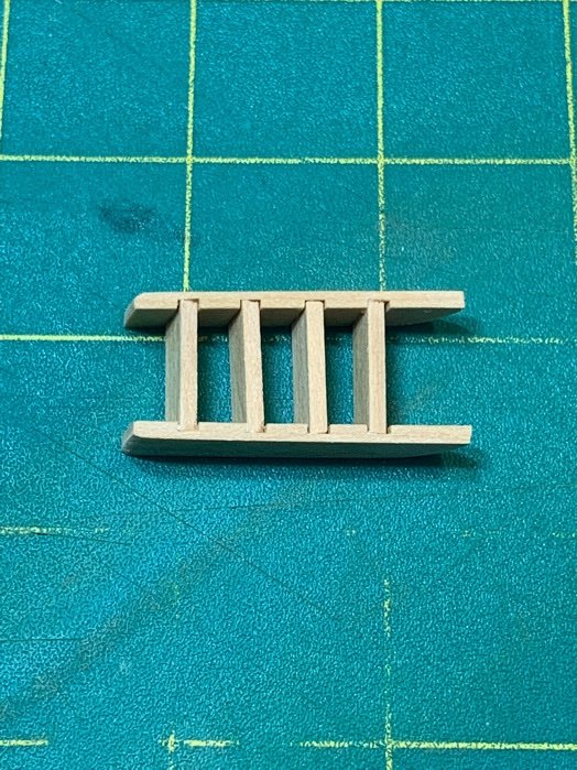
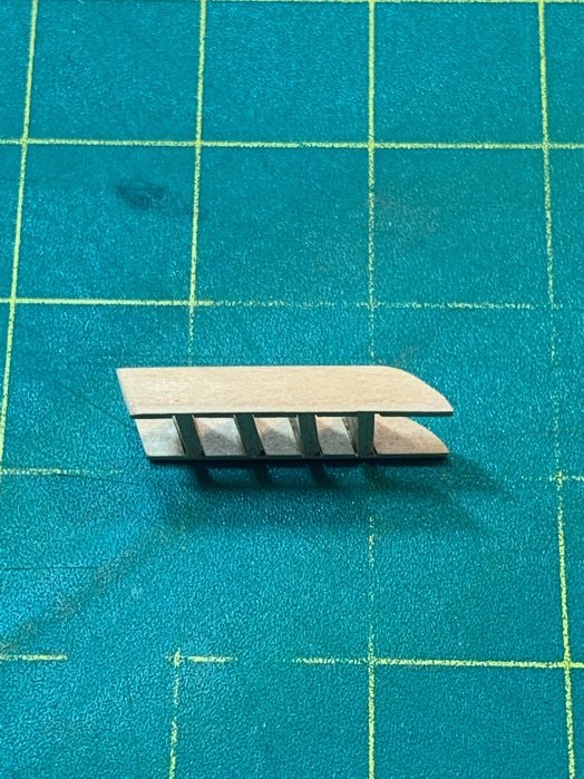
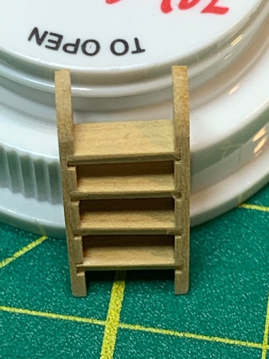
Finished up the other ladder. Yes, some folks mentioned the ladders are a bit ‘thick’. What the hell. 😁 It’s better than my first ladder I made for the Sultana.
Also pre trimmed and test fit the gudgeons. I made the decision to trim the gudgeons not to extend beyond the stern piece. Yes, it’s a deviation but not a big one. A lot of brigs (US brigs included) in this era did not wrap the gudgeons out beyond the stern piece.
It also saved me from trying to bend around the ‘fat’ planking which I did not sand level with the stern piece. So…lesson learned.
The fit looks good…and if I mount them as accurately after coppering, the rudder will both functional and removable. 👍🏽
Moving on….

-
Please tell me you haven’t given up on your Syren! 🙏🏻 Merry Christmas and happy flying!!!!
-
I plan to do individual tiles. Most builds approach the coppering this way.
-
Silk thread servings look awesome. Does the serving unwrap when you cut it? Is there any additional prep for served lines you do like coating in dilute glue, wax, etc. ?
-
2 hours ago, JJUSNRET said:
GREAT help to those of us who are doing this the first time. techniques used here will absolutely help in building any model. I am building CW Morgan and jus purchased Syren and I will absolutely use what I leaned here. THANK YOU!!!
@JJUSNRET JJ, you made my day! 😁 Really appreciate the kind accolade. And I assume you are Navy by your username. I was regular USAF (NCO), from a huge Navy family. I still know more military than civilians.
🇺🇸 Thank you for your service to our beloved country!!
-
-
-
Took a lesson from my own advice and decided to do a little side project. Ladders. Last time I made one I really didn’t have any idea what I was doing. This time, I’m operating with a few more brain cells of experience. 😁
-
I live on my Byrne’s saw. 🌲😎
-
Hi Ken!
I know there are a lot of builds out there…some are rough, others are like works from pros. Don’t compare yourself. It’s your ship, and and deviating from the plans is fun! A couple options: 1) Go without rivets at all (who is really going to check?) 2) Paint the hull white below the waterline instead of coppering.
For the foil not sticking, a lot of folks recommended sanding sealer or primer. It cleans up the wood surface and gives the foil something to stick to.
When your build gets you stressed, do a side project to reset your head and allow your creative juices to give you ideas.
It’s a marathon!! (A really long one!)
Best
Pat
- Ryland Craze and VTHokiEE
-
 2
2
-
Hi @niwotwill Will,
If you go to post #123 in my log, your questions are directly addressed! 👍🏽
Hope that helps!
(0.4mm thickness) (1/8” cherry wood sections as sandwich bread 😁 ). Please note the correction. I'm sure this would work with sheets that are 1/16", but did a quick remeasure and find that sandwich sections (cherry wood) was closer to 1/8'. Either way...very easy to cut. One thing to keep in mind is to line up the grain of the wood with the direction of the cut for the strips...cuts much easier I think.
-
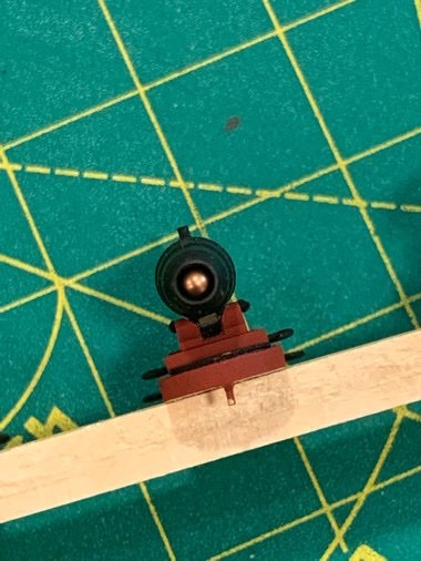
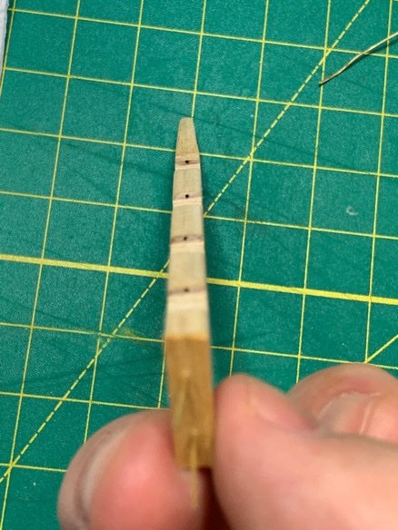
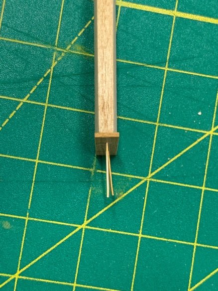
Still futzing with the rudder. Prepared all the pintles. Dry fit with nails. Used a manicure shaping tool to press in the wood in the rudder cavity to ensure a smooth fit with gudgeons. Looking fairly decent. Will use the rudder as it is to mark the gudgeons placement and get those prepared.
Not sure how everyone else does it…but I really don’t trust myself in this part. But I am determined to ensure I can remove the rudder.
I could have embedded the pins in the pintles. But I wanted some 'room' to play if things got finicky and the fit too tight/restrictive. I can always replace the thinner wire with a 20G copper section which would fit perfectly in the pintle.
Moving on…
-
3 hours ago, CPDDET said:
Beautiful as always.
In truth…I’m posting my little successes on the easy stuff as I build up my courage to attack the copper plating.
I’m chicken. 😖
-
-
Those kit dead eyes look great!
-
2 hours ago, niwotwill said:
Very nice Patrick. If I take mine off will you make me some? HA HA HA
Regards
Will
Not so fast!! The jury is still out on whether these are going to look good mounted…much less work as I hope!
Fingers crossed!!
-
11 minutes ago, CPDDET said:
Thank YOU, for sharing your techniques. You're a huge help / mentor to us newbies.
LOL! Dave, even on your bad days, I think your work far outshines mine! But I’m glad you can find some new ideas in my build log!!

- CPDDET and Ryland Craze
-
1
-
 1
1
-
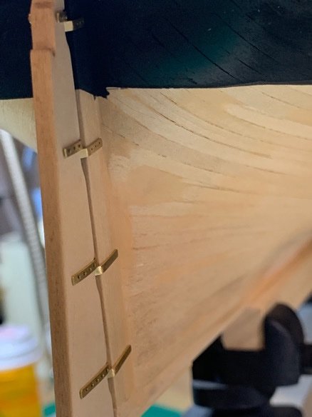
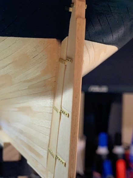
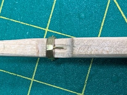
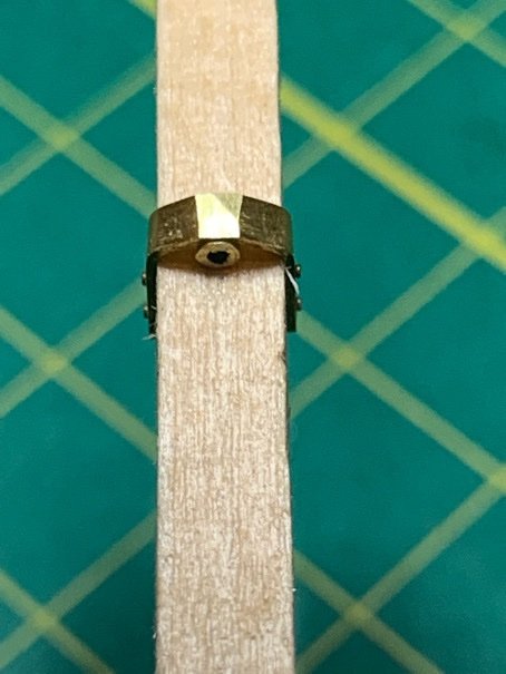
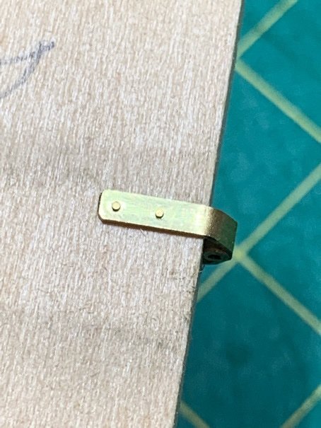
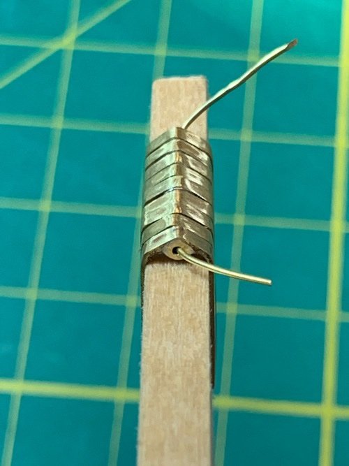
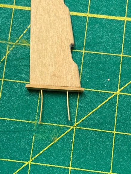
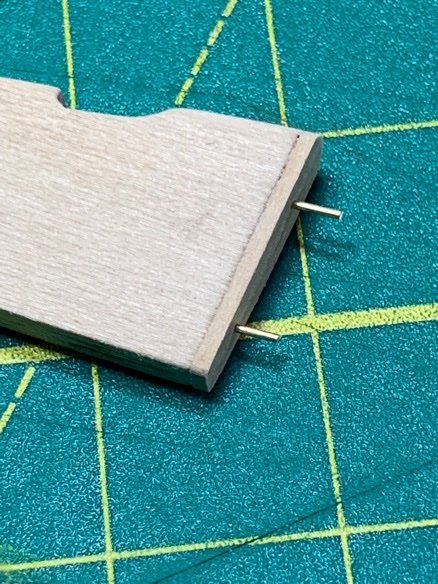
It occurred to me when trying the P&Gs on scrap basswood piece (same width as sternpost) that the width of the brass strap needs to be considered when the pintle and corresponding gudgeons are aligned (i.e. opposite direction of each other). So I decided to sand off a bit of the brass at the ‘peak’ where the hollow brass tubing sits.
Also tried the small brass nails to lock it in place…and that sucker does not move!!
Moving on…
-
Dear @CPDDET Dave,
Thanks again for the kind words. You and the other shipmates kudos always keeps wind in my sails!
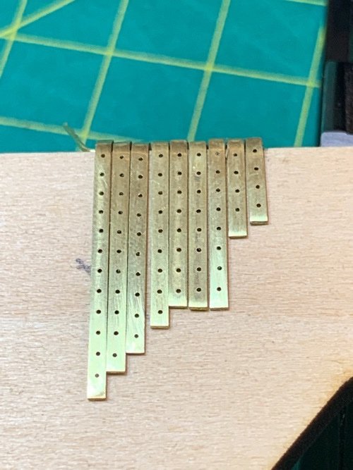
Ok. My technique for nail holes in my P&Gs is as follows. It might sound stupid…but it works! A mini drill press equipped with an x-y table are sort of mandatory for this to work.
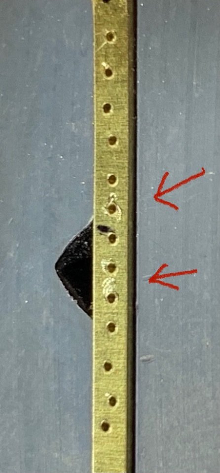
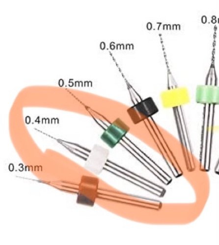
My initial trials with a #78 drill bit(s) met with disaster. I broke two before I went to the high precision PCB bits (0.4mm) and broke two of those little buggers. 🤬
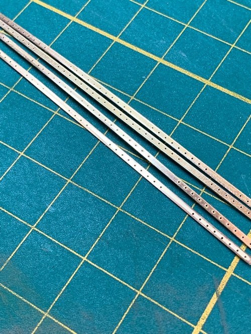
The pics below shows one of my strip attempts. You can see where the drill bit was drifting (red arrows) as it scored the brass. The bits invariably snapped. I was beginning to doubt my choice of 0.3mm brass nails! Those bloody things are tiny.
AND BEFORE ANYONE ASKS…YES, I HEATED UP THE BRASS!! I don’t believe it was annealed, as it was pretty soft. But the nail pattern looks like a drunk Irishman heading home on Saturday morning (said the drunk Irishman typing in a ship log).
Hard to believe that was done with an x-y table. That’s how much the tiny bits drift before they gain purchase. 😣
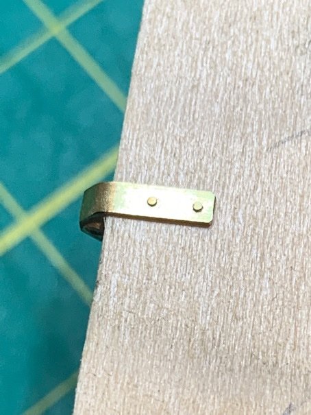
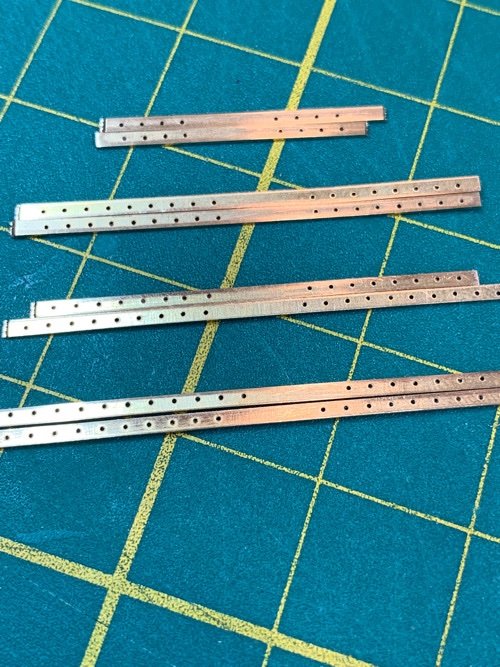
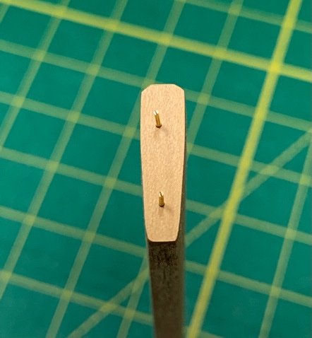
I figured giving the drill bit a cup or starter point would work. Using a hammer and awl just deformed the brass strip. So I opted for using an engraving cutter. It worked beautifully. I just pressed it lightly into the strip of brass and it made a prefect little divot.
Dremel 105 Engraving Cutter, 1/8" Shank , Gray https://www.amazon.com/dp/B00008Z9ZT/ref=cm_sw_r_cp_api_glt_fabc_AT62H13H1PW0ZN5DRMA5

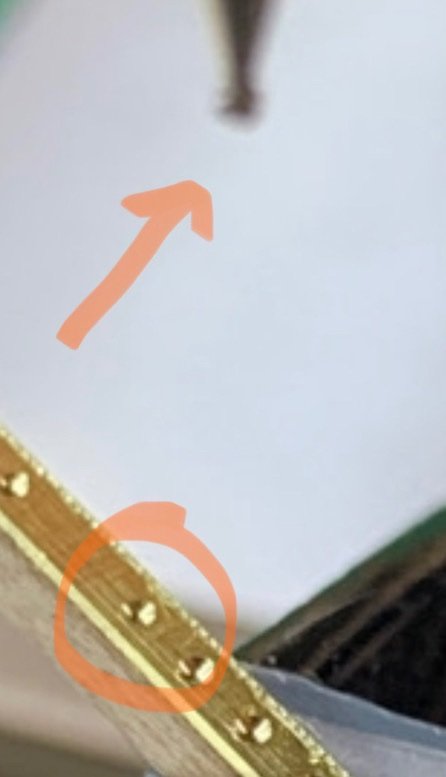
After that, I just repeated the drill pattern using a tungsten high precision drill bit 0.4mm. Both the drill bits and Dremel engraving cutter are really cheap (yes…Amazon).
The results speak for themselves.
So…that’s my workaround. After I adopted this method, I cranked through the drilling portion in 45 min using one drill bit. No trouble.

-
43 minutes ago, CPDDET said:
Beautiful work, Pat!
I would be very greatfull for a photo or link to the "round head drill bit" you refered to. Keeping wire size bits from straying has been an issue for me. Sounds like you have a good solution.
I snapped about 4 drill bits before I arrived at this solution and it worked like a charm. I’ll add a separate post with more info, Dave. -
The one area which invariably ends up making or breaking the exterior view of a ship model is the Pintles and Gudgeons. These are really tricky for me, as few folks really break down the making, and installing of these things.
So…been noodling and researching for a while…and experimenting quite a bit. For my Sultana, I ended up using paper because I couldn’t work with metal. This time I wanted to really give it the ol’ college try to get a good result using brass.
So…here is where I’m at so far. Long post coming:
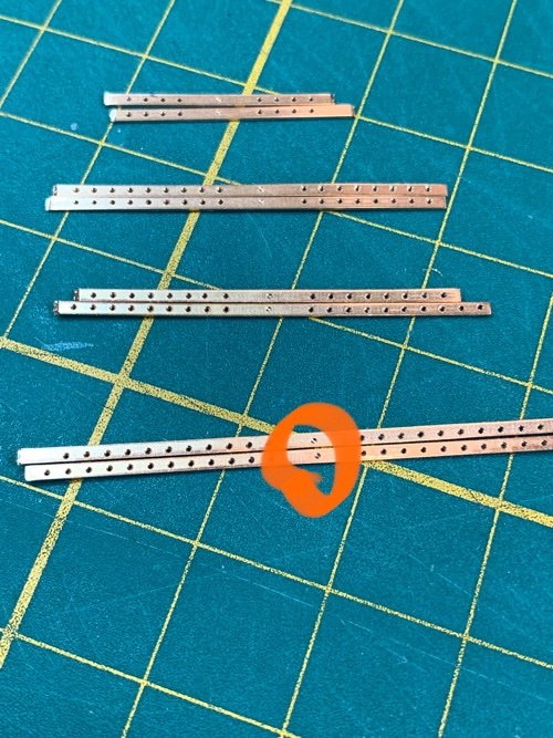
1. Recut my P&G’s thinner to more closely match the plans. I used my original brass sheet/cherry wood sandwich.
2. Separated one wooden side from all strips.
3. After cleaning off the spray glue from the exposed metal side with acetone (nail polish remover), I used a round head drill bit (wood carving Dremel bit) to score in a ‘divot’. This keeps the tiny drill bit from floating when I drilled the actual nail holes. Nothing worse than uneven nail holes!
4. Then I drilled the actual holes.

5. Then I separated the other half of the wood from the brass piece, cleaned it up, and cut it up into rough sections.
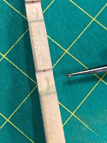
The interior sides have the larger nail score mark and a center mark I put in to ensure my bending was consistent at the center.
6. I decided for a triangular bend rather than a rounded one. It ensured I had centered the brass rod in each P&G. I used a wire bender…no jig. I eyeballed it…because I simply could not figure out how to make a good bending jig!!!!
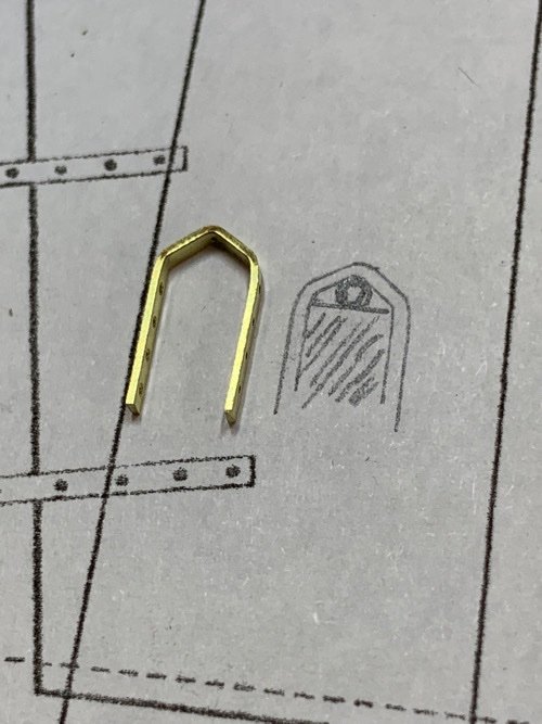
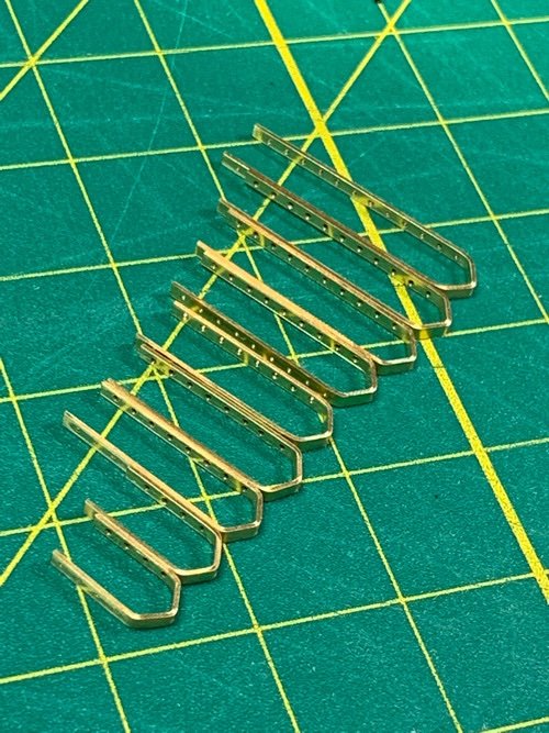
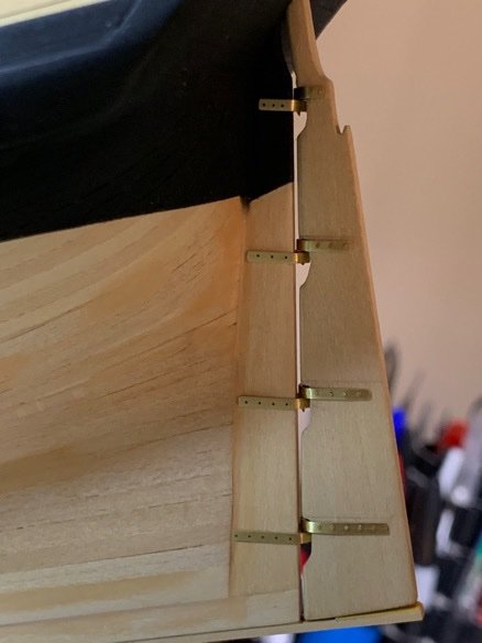
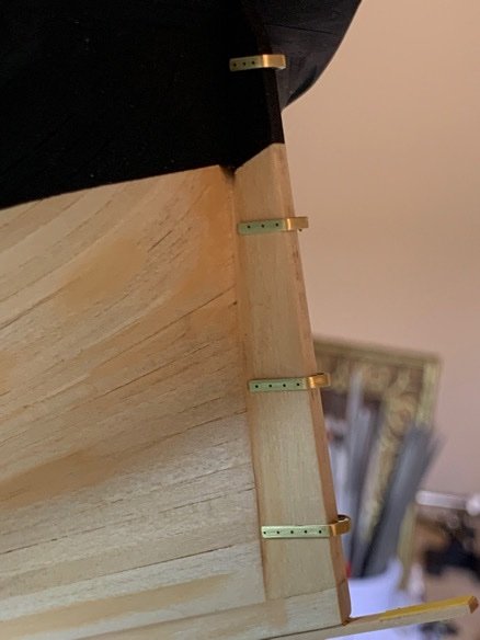
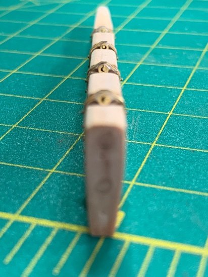
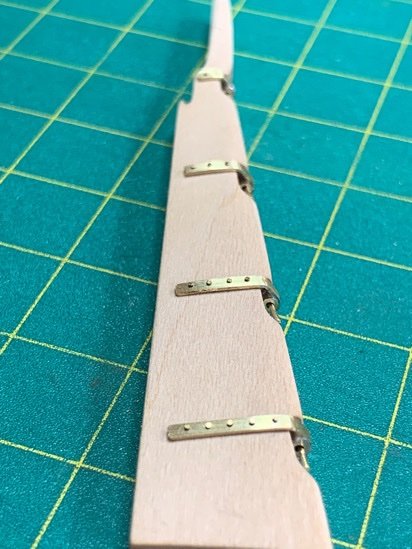
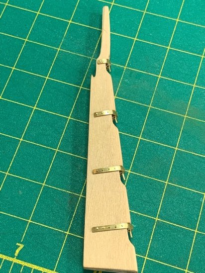
7. Soldered in the brass tubing, cut, and polished up the P&Gs. I made a bunch of various sizes. I can trim and adjust as needed during fitting.
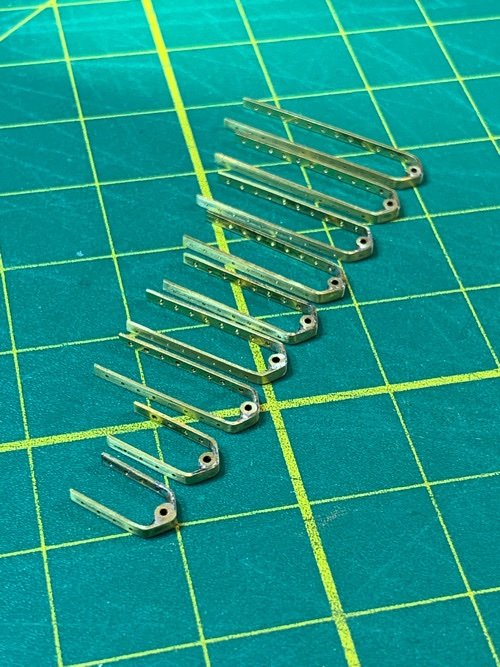
Placed them on a fake stern piece to ensure the general fit and alignment. I was pretty happy with the center alignment and width. Fit was nice and clean…no gaps.
Still have a long way to go, but these are the first metal P&Gs I ever made…and I’m pretty happy with them so far.
Moving on.
- Gahm, Ryland Craze, GrandpaPhil and 2 others
-
4
-
 1
1
-
1 hour ago, abelson said:
Excellent, detailed roof! You have a lot of patience - a ship builders virtue.
Thanks, Abe! Your build continues to inspire me as well. 👍🏽
US Brig Syren 1803 by Overworked724 – Model Shipways – Scale 1:64
in - Kit build logs for subjects built from 1801 - 1850
Posted · Edited by Overworked724
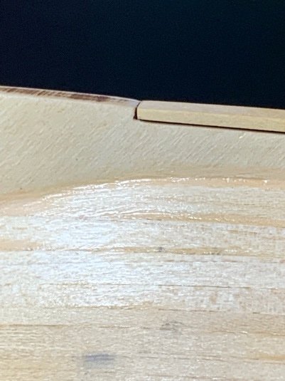
Holy crap…those close ups really magnify the wood filler! I have to start my coppering. 😳