


EdatWycliffe
-
Posts
119 -
Joined
-
Last visited
Reputation Activity
-

 EdatWycliffe got a reaction from abelson in US Brig Syren by EdatWycliffe - Model Shipways - 1:64 - 18 gun brig
Chapter 4 Stern Framing:
I'm about three weeks late posting this entry. Started the upper hull framing and couldn't stop. (More on the next post re hull planking.)
As you will see from the five photos, below. I had my hands full getting the stern framing to be half way acceptable. The sin of not perfectly squaring the bulwarks and center former revisited me with a vengeance. The formers were off kilter in three planes! I took a very deep breath and remembered that its just wood that can be built up and carved down. As you can see from the different color stern frames (some white and some brown from the laser burn), I practically rebuilt three frames to get them all aligned. I've got to noodle around with the ports a bit to get them symmetrical, but that will come later.
Meanwhile, I reading ahead in many of your build logs and in Chuck's original practicum to avoid as many pitfalls as I can. Much appreciate Dirk's and Larry's advice along the way. (Dirk, I secured some Danish oil and Humbrol matte black as you suggest. Thanks.
Ed
-
 EdatWycliffe got a reaction from Jack12477 in US Brig Syren by Hipexec - FINISHED - Model Shipways - 1:64 - building as USS Argus
Looking very good, Rich. I’ve temporarily halted my Syren build while I research the best way to furl sails. (The research is as much fun as the actual build.) I think I figured out the staysails and I’m now working on the square sales. Ed
-
 EdatWycliffe got a reaction from HIPEXEC in US Brig Syren by Hipexec - FINISHED - Model Shipways - 1:64 - building as USS Argus
Looking very good, Rich. I’ve temporarily halted my Syren build while I research the best way to furl sails. (The research is as much fun as the actual build.) I think I figured out the staysails and I’m now working on the square sales. Ed
-
 EdatWycliffe got a reaction from jablackwell in US Brig Syren by Hipexec - FINISHED - Model Shipways - 1:64 - building as USS Argus
Very nice the deadeyes look perfectly even. What procedure did you use? I usually hang the top deadeye evenly first. Ed
-
EdatWycliffe got a reaction from HIPEXEC in US Brig Syren by Hipexec - FINISHED - Model Shipways - 1:64 - building as USS Argus
Very nice the deadeyes look perfectly even. What procedure did you use? I usually hang the top deadeye evenly first. Ed
-
EdatWycliffe got a reaction from HIPEXEC in US Brig Syren by Hipexec - FINISHED - Model Shipways - 1:64 - building as USS Argus
Thanks, Rich. I’ll try it.
-
 EdatWycliffe got a reaction from GrandpaPhil in Fair American by EdatWycliffe - FINISHED - Model Shipways - Kit-bashed per LSS Practicum
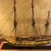
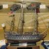
Fair American has launched two years and two months after the keel was laid. Some pictures of completed the ship are attached. Most important, thanks to all of you who helped me through this first ship after the Phantom starter kit, especially Bob (Rafine) and Ken (KenW). In a couple of weeks, I'll start Syren with new wood to be ordered from Timberyard Crown (Jason is great to work with) and rope and blocks from Chuck at Syren. Thanks, much, everyone!
-
EdatWycliffe got a reaction from GrandpaPhil in Fair American by EdatWycliffe - FINISHED - Model Shipways - Kit-bashed per LSS Practicum
Finally some Fair American buildlog photos. Overall, the work is progressing. The spritsail yardarm, gaff, spanker boom, lower yard arms and lower yard arms have all been hoisted and pinned. (I also rigged the main topmast staysail downhaul and halyard, the main topgallant staysail downhaul and halyard and the Burton tackles.) I'm using the rigging order described in the Syren instructions.
The gaff, boom and spritsail are fully rigged. I also added boom guys since I thought that made sense to help guide the boom to the port and starboard. The slings and lifts have been added to the lower yardarms. Braces, clues, sheets and tacks for the lower yard arms will wait until the topsail and topgallant yard arms are mounted and rigged. The main topsail has its yard parrels installed, as well as the tye, halyard, halyard runner and halyard tackle. (I'm very grateful for help from KenW and Rafine). (I tried to conform to Petersson and Lees as much as I could, but given the limited belaying points and belaying plan in the FA kit, I added a pinch of imagination.)
The topgallant yard arm needs to be installed before I can rig the main topsail lifts (per Lees). The photos:
Boom, Gaff and Guys
Sprit sail
lower yard arms and spritsail overview
main top with parrels not yet rigged
main top with Burton tackles waiting to be belayed
spritsail rigging
yard arm overview with main topsail pinned
main topsail halyard runner (port) and tackle (starboard)
fore topsail yard arm with Burton tackles belayed to main top
fore lower yard arm and spritsail yard arm
view down from onto the main and fore tops
As far a workmanship and skill sets--that too is a work in progress (from a D when I started to a C+/B- today. I made a lot of errors. Some are visible; some not, but I've learned from them all. Still great fun and wonderful learning experience. (I look forward to Syren as my next build.)
Ed (EdatWycliffe)
-
EdatWycliffe got a reaction from HIPEXEC in US Brig Syren by Hipexec - FINISHED - Model Shipways - 1:64 - building as USS Argus
Thanks Nice work, Rich, and Inspirational. I’m taking July off from the build to do research with respect to proper furling and rigging. I enjoy that part of the hobby almost as much as the build. Ed
-
EdatWycliffe got a reaction from HIPEXEC in US Brig Syren by Hipexec - FINISHED - Model Shipways - 1:64 - building as USS Argus
Good morning, Rich. I just logged on to your Brig Syren (Argus) log for the first time. I am also building Syren and just finished the main and fore masts. [Before I go further, I wish you a complete recovery from the injuries you suffered. Time heals most all.] I’ll be traveling in July, but will use the month to figure out how to bend furled sails to the model. I’ve never done that and, of course, the Syren instruction manual doesn’t cover the subject. There’s a lot of literature on the preparation of the sails, but not much on bending them to the yards. I do have Landlubber Mike’s excellent treatise, so my first task will be to learn which blocks on the yards and other spars are used for clews, leaches, bunts, and sheets. When I return, I’ll bring my build log up to snuff. In the meantime, I look forward to following your excellent build. Ed
-
 EdatWycliffe got a reaction from tasmanian in Furled sails
Thanks, Kenny. I’ll look at the video this evening. Bending sails is a challenge and I’m happy to have the help. Ed
-
 EdatWycliffe got a reaction from druxey in Furled sails
Thanks much druxey. Appreciate the suggestion. I‘ll order the book. Ed
-
 EdatWycliffe got a reaction from thibaultron in Furled sails
Dan, I’m building Syren and about ready to step masts. I want to furl sails and have read extensively about making the sail and furling it. But I can’t find any source to tell me how to rig the sails. Certainly the clew lines, leach lines, etc. are rigged differently from rigging without sales. Simply put, where can I learn how to rig a furled sail? Thanks EdatWycliffe
-
 EdatWycliffe got a reaction from mtaylor in Furled sails
Dan, I’m building Syren and about ready to step masts. I want to furl sails and have read extensively about making the sail and furling it. But I can’t find any source to tell me how to rig the sails. Certainly the clew lines, leach lines, etc. are rigged differently from rigging without sales. Simply put, where can I learn how to rig a furled sail? Thanks EdatWycliffe
-
 EdatWycliffe got a reaction from KenW in US Brig Syren by EdatWycliffe - Model Shipways - 1:64 - 18 gun brig
Chapter 4 Stern Framing:
I'm about three weeks late posting this entry. Started the upper hull framing and couldn't stop. (More on the next post re hull planking.)
As you will see from the five photos, below. I had my hands full getting the stern framing to be half way acceptable. The sin of not perfectly squaring the bulwarks and center former revisited me with a vengeance. The formers were off kilter in three planes! I took a very deep breath and remembered that its just wood that can be built up and carved down. As you can see from the different color stern frames (some white and some brown from the laser burn), I practically rebuilt three frames to get them all aligned. I've got to noodle around with the ports a bit to get them symmetrical, but that will come later.
Meanwhile, I reading ahead in many of your build logs and in Chuck's original practicum to avoid as many pitfalls as I can. Much appreciate Dirk's and Larry's advice along the way. (Dirk, I secured some Danish oil and Humbrol matte black as you suggest. Thanks.
Ed
-
 EdatWycliffe got a reaction from Ryland Craze in US Brig Syren by EdatWycliffe - Model Shipways - 1:64 - 18 gun brig
Chapter 4 Stern Framing:
I'm about three weeks late posting this entry. Started the upper hull framing and couldn't stop. (More on the next post re hull planking.)
As you will see from the five photos, below. I had my hands full getting the stern framing to be half way acceptable. The sin of not perfectly squaring the bulwarks and center former revisited me with a vengeance. The formers were off kilter in three planes! I took a very deep breath and remembered that its just wood that can be built up and carved down. As you can see from the different color stern frames (some white and some brown from the laser burn), I practically rebuilt three frames to get them all aligned. I've got to noodle around with the ports a bit to get them symmetrical, but that will come later.
Meanwhile, I reading ahead in many of your build logs and in Chuck's original practicum to avoid as many pitfalls as I can. Much appreciate Dirk's and Larry's advice along the way. (Dirk, I secured some Danish oil and Humbrol matte black as you suggest. Thanks.
Ed
-
 EdatWycliffe got a reaction from augie in US Brig Syren by EdatWycliffe - Model Shipways - 1:64 - 18 gun brig
Thomas, thanks much for the cannonade information. I'm still a long way from assembling them, but I like to plan ahead. I'll definitely follow up with Cornwall Model Boats. I've just finished the gun ports, sweep ports and stern framing and will post an update early next week. (Flying to New York City this weekend to see the grandkids.) The stern framing was difficult and I had to sand down the frames in some places and build them up in others. Keeping the frames correctly aligned in three planes was a real bear! I think thinks turned out OK, but the proof of the pudding will be in the eating. Thanks again.
And thanks to all who are following this log. It adds a very enjoyable dimension to the build. Ed
-
 EdatWycliffe got a reaction from Gahm in US Brig Syren by EdatWycliffe - Model Shipways - 1:64 - 18 gun brig
Gun and sweep ports:
Wow, what a job! It seems an eternity of measuring, fairing, cutting, gluing and sanding the gun and sweep ports. But, they are finally done, together with the sheave frames (two each, port and starboard). The eight pics, below, memorialize the effort.
#1. I pinned a batten on the starboard side of the hull to get a good run for the gun port sills. I guess fairing was OK up to now because the run was smooth with no dips or twists and was pretty close to the laser guide marks on the bulwarks.
#2. The sills were cut and glued on the starboard side. Seems like this should have been a simple step, but I cut the sills too short too often and then recut them a bit longer and sanded them to a comfortable length so they didn't push the bulwarks our of square. I then sanded the sills inboard and outboard.
#3. I added the sills to the port side then sanded the them inboard and outboard. I kept in mind Chuck's warning to maintain a smooth curve and fair the work as you go. I then measured, cut and glued the lintels, port and starboard, measuring 15/32"up from the top of each sill. Because the sills had a decent run, the lintels came out OK. The lintels were then sanded inboard and outboard, watching that the bulwark extensions at the cap rail didn't get too thin, and trying to maintain the contours of the bulwark extensions along the length of the lintels.
#4. Then things got a bit dicier. I clamped the port template that Chuck was kind enough to send and saw that the bulkheads were nearly spot on. However the starboard template indicated that the bulwarks were out of square. (For all of the effort I put into squaring the bulkheads to the bulkhead former, I could have done better. I think that the error occurred at the filler-block stage. I measured the thickness of the fillers between each bulkhead on the port and starboard side of the bulkhead, keeping those measurements constant. Instead, I should have measured the distance between each bulkhead, port and starboard, from a consistent place, for example from the tip of the stern at the center of the bulkhead former. I must have made a measurement error in one of the first filler blocks on the starboard side and simply repeated that error as I completed the filler blocks on that side. With this error, the vertical gun-port frames on the starboard side would be way off measurement.
However, I took great solace in Chuck's repeated message that adjustments to the vertical frames were easily made. So, onward and upward. . .
#5. I marked the vertical frames on the port-side sills (the accurate side) where the template indicated they should be placed. The vertical pieces were measured, cut and glued, making sure that the vertical frames were 15/32" apart, top and bottom. This is where the adjustment comes in. I ignored the starboard template. Instead, I pinned a long piece of dental floss (it doesn't stretch) to the center of the tip of the stem. (You can just see the floss at the bow.) I then used the floss to measure the distance from the pin to each port-side vertical frame. I then swung the floss to the starboard side and marked the same place where the port-side vertical frame was placed. Hopefully, the port and starboard gun-port frames will now be exactly opposite one another.
#6. The template (with the sills and lintels cut away) was re-clamped to the port side (the accurate side). The placement of the vertical sweep port frames was marked on the sills and the horizontal sweep port frames were added, port and starboard, 1/8" above the sills. The horizontal frames were then sanded inboard and outboard. I paid close attention to keeping the contour of the bulwark extensions along the entire length of the horizontal sweep-port frames.
#7. I measured, cut and glued the vertical sweep-port frames on the port side where marked. (I used a small piece of 1/8" x 1/8" strip as a tool to make sure that the sweep ports were square.) The vertical frames for the sweep ports were then added to the starboard side using the same dental-floss measuring method to make sure that the sweep ports will be opposite one another, port and starboard. More sanding until the sweep port frames blended into the gun port framing. I then made framing for the four sheaves ( a la Dubz)--one each above bulkheads D and 4, port and starboard. (The sheave frames are just visible in pic #8.)
#8. More sanding and fairing. The framing now feels smooth to the touch and looks good to the eye. I sure hope that it is up to snuff when planking begins.
On to the stern frame. . .
-
 EdatWycliffe got a reaction from _SalD_ in US Brig Syren by EdatWycliffe - Model Shipways - 1:64 - 18 gun brig
Gun and sweep ports:
Wow, what a job! It seems an eternity of measuring, fairing, cutting, gluing and sanding the gun and sweep ports. But, they are finally done, together with the sheave frames (two each, port and starboard). The eight pics, below, memorialize the effort.
#1. I pinned a batten on the starboard side of the hull to get a good run for the gun port sills. I guess fairing was OK up to now because the run was smooth with no dips or twists and was pretty close to the laser guide marks on the bulwarks.
#2. The sills were cut and glued on the starboard side. Seems like this should have been a simple step, but I cut the sills too short too often and then recut them a bit longer and sanded them to a comfortable length so they didn't push the bulwarks our of square. I then sanded the sills inboard and outboard.
#3. I added the sills to the port side then sanded the them inboard and outboard. I kept in mind Chuck's warning to maintain a smooth curve and fair the work as you go. I then measured, cut and glued the lintels, port and starboard, measuring 15/32"up from the top of each sill. Because the sills had a decent run, the lintels came out OK. The lintels were then sanded inboard and outboard, watching that the bulwark extensions at the cap rail didn't get too thin, and trying to maintain the contours of the bulwark extensions along the length of the lintels.
#4. Then things got a bit dicier. I clamped the port template that Chuck was kind enough to send and saw that the bulkheads were nearly spot on. However the starboard template indicated that the bulwarks were out of square. (For all of the effort I put into squaring the bulkheads to the bulkhead former, I could have done better. I think that the error occurred at the filler-block stage. I measured the thickness of the fillers between each bulkhead on the port and starboard side of the bulkhead, keeping those measurements constant. Instead, I should have measured the distance between each bulkhead, port and starboard, from a consistent place, for example from the tip of the stern at the center of the bulkhead former. I must have made a measurement error in one of the first filler blocks on the starboard side and simply repeated that error as I completed the filler blocks on that side. With this error, the vertical gun-port frames on the starboard side would be way off measurement.
However, I took great solace in Chuck's repeated message that adjustments to the vertical frames were easily made. So, onward and upward. . .
#5. I marked the vertical frames on the port-side sills (the accurate side) where the template indicated they should be placed. The vertical pieces were measured, cut and glued, making sure that the vertical frames were 15/32" apart, top and bottom. This is where the adjustment comes in. I ignored the starboard template. Instead, I pinned a long piece of dental floss (it doesn't stretch) to the center of the tip of the stem. (You can just see the floss at the bow.) I then used the floss to measure the distance from the pin to each port-side vertical frame. I then swung the floss to the starboard side and marked the same place where the port-side vertical frame was placed. Hopefully, the port and starboard gun-port frames will now be exactly opposite one another.
#6. The template (with the sills and lintels cut away) was re-clamped to the port side (the accurate side). The placement of the vertical sweep port frames was marked on the sills and the horizontal sweep port frames were added, port and starboard, 1/8" above the sills. The horizontal frames were then sanded inboard and outboard. I paid close attention to keeping the contour of the bulwark extensions along the entire length of the horizontal sweep-port frames.
#7. I measured, cut and glued the vertical sweep-port frames on the port side where marked. (I used a small piece of 1/8" x 1/8" strip as a tool to make sure that the sweep ports were square.) The vertical frames for the sweep ports were then added to the starboard side using the same dental-floss measuring method to make sure that the sweep ports will be opposite one another, port and starboard. More sanding until the sweep port frames blended into the gun port framing. I then made framing for the four sheaves ( a la Dubz)--one each above bulkheads D and 4, port and starboard. (The sheave frames are just visible in pic #8.)
#8. More sanding and fairing. The framing now feels smooth to the touch and looks good to the eye. I sure hope that it is up to snuff when planking begins.
On to the stern frame. . .
-
EdatWycliffe got a reaction from augie in US Brig Syren by EdatWycliffe - Model Shipways - 1:64 - 18 gun brig
Gun and sweep ports:
Wow, what a job! It seems an eternity of measuring, fairing, cutting, gluing and sanding the gun and sweep ports. But, they are finally done, together with the sheave frames (two each, port and starboard). The eight pics, below, memorialize the effort.
#1. I pinned a batten on the starboard side of the hull to get a good run for the gun port sills. I guess fairing was OK up to now because the run was smooth with no dips or twists and was pretty close to the laser guide marks on the bulwarks.
#2. The sills were cut and glued on the starboard side. Seems like this should have been a simple step, but I cut the sills too short too often and then recut them a bit longer and sanded them to a comfortable length so they didn't push the bulwarks our of square. I then sanded the sills inboard and outboard.
#3. I added the sills to the port side then sanded the them inboard and outboard. I kept in mind Chuck's warning to maintain a smooth curve and fair the work as you go. I then measured, cut and glued the lintels, port and starboard, measuring 15/32"up from the top of each sill. Because the sills had a decent run, the lintels came out OK. The lintels were then sanded inboard and outboard, watching that the bulwark extensions at the cap rail didn't get too thin, and trying to maintain the contours of the bulwark extensions along the length of the lintels.
#4. Then things got a bit dicier. I clamped the port template that Chuck was kind enough to send and saw that the bulkheads were nearly spot on. However the starboard template indicated that the bulwarks were out of square. (For all of the effort I put into squaring the bulkheads to the bulkhead former, I could have done better. I think that the error occurred at the filler-block stage. I measured the thickness of the fillers between each bulkhead on the port and starboard side of the bulkhead, keeping those measurements constant. Instead, I should have measured the distance between each bulkhead, port and starboard, from a consistent place, for example from the tip of the stern at the center of the bulkhead former. I must have made a measurement error in one of the first filler blocks on the starboard side and simply repeated that error as I completed the filler blocks on that side. With this error, the vertical gun-port frames on the starboard side would be way off measurement.
However, I took great solace in Chuck's repeated message that adjustments to the vertical frames were easily made. So, onward and upward. . .
#5. I marked the vertical frames on the port-side sills (the accurate side) where the template indicated they should be placed. The vertical pieces were measured, cut and glued, making sure that the vertical frames were 15/32" apart, top and bottom. This is where the adjustment comes in. I ignored the starboard template. Instead, I pinned a long piece of dental floss (it doesn't stretch) to the center of the tip of the stem. (You can just see the floss at the bow.) I then used the floss to measure the distance from the pin to each port-side vertical frame. I then swung the floss to the starboard side and marked the same place where the port-side vertical frame was placed. Hopefully, the port and starboard gun-port frames will now be exactly opposite one another.
#6. The template (with the sills and lintels cut away) was re-clamped to the port side (the accurate side). The placement of the vertical sweep port frames was marked on the sills and the horizontal sweep port frames were added, port and starboard, 1/8" above the sills. The horizontal frames were then sanded inboard and outboard. I paid close attention to keeping the contour of the bulwark extensions along the entire length of the horizontal sweep-port frames.
#7. I measured, cut and glued the vertical sweep-port frames on the port side where marked. (I used a small piece of 1/8" x 1/8" strip as a tool to make sure that the sweep ports were square.) The vertical frames for the sweep ports were then added to the starboard side using the same dental-floss measuring method to make sure that the sweep ports will be opposite one another, port and starboard. More sanding until the sweep port frames blended into the gun port framing. I then made framing for the four sheaves ( a la Dubz)--one each above bulkheads D and 4, port and starboard. (The sheave frames are just visible in pic #8.)
#8. More sanding and fairing. The framing now feels smooth to the touch and looks good to the eye. I sure hope that it is up to snuff when planking begins.
On to the stern frame. . .
-
 EdatWycliffe got a reaction from GuntherMT in US Brig Syren by EdatWycliffe - Model Shipways - 1:64 - 18 gun brig
Gun and sweep ports:
Wow, what a job! It seems an eternity of measuring, fairing, cutting, gluing and sanding the gun and sweep ports. But, they are finally done, together with the sheave frames (two each, port and starboard). The eight pics, below, memorialize the effort.
#1. I pinned a batten on the starboard side of the hull to get a good run for the gun port sills. I guess fairing was OK up to now because the run was smooth with no dips or twists and was pretty close to the laser guide marks on the bulwarks.
#2. The sills were cut and glued on the starboard side. Seems like this should have been a simple step, but I cut the sills too short too often and then recut them a bit longer and sanded them to a comfortable length so they didn't push the bulwarks our of square. I then sanded the sills inboard and outboard.
#3. I added the sills to the port side then sanded the them inboard and outboard. I kept in mind Chuck's warning to maintain a smooth curve and fair the work as you go. I then measured, cut and glued the lintels, port and starboard, measuring 15/32"up from the top of each sill. Because the sills had a decent run, the lintels came out OK. The lintels were then sanded inboard and outboard, watching that the bulwark extensions at the cap rail didn't get too thin, and trying to maintain the contours of the bulwark extensions along the length of the lintels.
#4. Then things got a bit dicier. I clamped the port template that Chuck was kind enough to send and saw that the bulkheads were nearly spot on. However the starboard template indicated that the bulwarks were out of square. (For all of the effort I put into squaring the bulkheads to the bulkhead former, I could have done better. I think that the error occurred at the filler-block stage. I measured the thickness of the fillers between each bulkhead on the port and starboard side of the bulkhead, keeping those measurements constant. Instead, I should have measured the distance between each bulkhead, port and starboard, from a consistent place, for example from the tip of the stern at the center of the bulkhead former. I must have made a measurement error in one of the first filler blocks on the starboard side and simply repeated that error as I completed the filler blocks on that side. With this error, the vertical gun-port frames on the starboard side would be way off measurement.
However, I took great solace in Chuck's repeated message that adjustments to the vertical frames were easily made. So, onward and upward. . .
#5. I marked the vertical frames on the port-side sills (the accurate side) where the template indicated they should be placed. The vertical pieces were measured, cut and glued, making sure that the vertical frames were 15/32" apart, top and bottom. This is where the adjustment comes in. I ignored the starboard template. Instead, I pinned a long piece of dental floss (it doesn't stretch) to the center of the tip of the stem. (You can just see the floss at the bow.) I then used the floss to measure the distance from the pin to each port-side vertical frame. I then swung the floss to the starboard side and marked the same place where the port-side vertical frame was placed. Hopefully, the port and starboard gun-port frames will now be exactly opposite one another.
#6. The template (with the sills and lintels cut away) was re-clamped to the port side (the accurate side). The placement of the vertical sweep port frames was marked on the sills and the horizontal sweep port frames were added, port and starboard, 1/8" above the sills. The horizontal frames were then sanded inboard and outboard. I paid close attention to keeping the contour of the bulwark extensions along the entire length of the horizontal sweep-port frames.
#7. I measured, cut and glued the vertical sweep-port frames on the port side where marked. (I used a small piece of 1/8" x 1/8" strip as a tool to make sure that the sweep ports were square.) The vertical frames for the sweep ports were then added to the starboard side using the same dental-floss measuring method to make sure that the sweep ports will be opposite one another, port and starboard. More sanding until the sweep port frames blended into the gun port framing. I then made framing for the four sheaves ( a la Dubz)--one each above bulkheads D and 4, port and starboard. (The sheave frames are just visible in pic #8.)
#8. More sanding and fairing. The framing now feels smooth to the touch and looks good to the eye. I sure hope that it is up to snuff when planking begins.
On to the stern frame. . .
-
 EdatWycliffe got a reaction from Dubz in US Brig Syren by EdatWycliffe - Model Shipways - 1:64 - 18 gun brig
Gun and sweep ports:
Wow, what a job! It seems an eternity of measuring, fairing, cutting, gluing and sanding the gun and sweep ports. But, they are finally done, together with the sheave frames (two each, port and starboard). The eight pics, below, memorialize the effort.
#1. I pinned a batten on the starboard side of the hull to get a good run for the gun port sills. I guess fairing was OK up to now because the run was smooth with no dips or twists and was pretty close to the laser guide marks on the bulwarks.
#2. The sills were cut and glued on the starboard side. Seems like this should have been a simple step, but I cut the sills too short too often and then recut them a bit longer and sanded them to a comfortable length so they didn't push the bulwarks our of square. I then sanded the sills inboard and outboard.
#3. I added the sills to the port side then sanded the them inboard and outboard. I kept in mind Chuck's warning to maintain a smooth curve and fair the work as you go. I then measured, cut and glued the lintels, port and starboard, measuring 15/32"up from the top of each sill. Because the sills had a decent run, the lintels came out OK. The lintels were then sanded inboard and outboard, watching that the bulwark extensions at the cap rail didn't get too thin, and trying to maintain the contours of the bulwark extensions along the length of the lintels.
#4. Then things got a bit dicier. I clamped the port template that Chuck was kind enough to send and saw that the bulkheads were nearly spot on. However the starboard template indicated that the bulwarks were out of square. (For all of the effort I put into squaring the bulkheads to the bulkhead former, I could have done better. I think that the error occurred at the filler-block stage. I measured the thickness of the fillers between each bulkhead on the port and starboard side of the bulkhead, keeping those measurements constant. Instead, I should have measured the distance between each bulkhead, port and starboard, from a consistent place, for example from the tip of the stern at the center of the bulkhead former. I must have made a measurement error in one of the first filler blocks on the starboard side and simply repeated that error as I completed the filler blocks on that side. With this error, the vertical gun-port frames on the starboard side would be way off measurement.
However, I took great solace in Chuck's repeated message that adjustments to the vertical frames were easily made. So, onward and upward. . .
#5. I marked the vertical frames on the port-side sills (the accurate side) where the template indicated they should be placed. The vertical pieces were measured, cut and glued, making sure that the vertical frames were 15/32" apart, top and bottom. This is where the adjustment comes in. I ignored the starboard template. Instead, I pinned a long piece of dental floss (it doesn't stretch) to the center of the tip of the stem. (You can just see the floss at the bow.) I then used the floss to measure the distance from the pin to each port-side vertical frame. I then swung the floss to the starboard side and marked the same place where the port-side vertical frame was placed. Hopefully, the port and starboard gun-port frames will now be exactly opposite one another.
#6. The template (with the sills and lintels cut away) was re-clamped to the port side (the accurate side). The placement of the vertical sweep port frames was marked on the sills and the horizontal sweep port frames were added, port and starboard, 1/8" above the sills. The horizontal frames were then sanded inboard and outboard. I paid close attention to keeping the contour of the bulwark extensions along the entire length of the horizontal sweep-port frames.
#7. I measured, cut and glued the vertical sweep-port frames on the port side where marked. (I used a small piece of 1/8" x 1/8" strip as a tool to make sure that the sweep ports were square.) The vertical frames for the sweep ports were then added to the starboard side using the same dental-floss measuring method to make sure that the sweep ports will be opposite one another, port and starboard. More sanding until the sweep port frames blended into the gun port framing. I then made framing for the four sheaves ( a la Dubz)--one each above bulkheads D and 4, port and starboard. (The sheave frames are just visible in pic #8.)
#8. More sanding and fairing. The framing now feels smooth to the touch and looks good to the eye. I sure hope that it is up to snuff when planking begins.
On to the stern frame. . .
-
 EdatWycliffe got a reaction from ScottRC in US Brig Syren by EdatWycliffe - Model Shipways - 1:64 - 18 gun brig
Doing some initial planning for this build. Reading through the entire instruction book to get a feel for the overall model and checking out the build of some pros like Dubz, Augie and Thomas. Should be able to start the actual build in a few weeks. Just finished MS kit Fair American (Kitbashed per Lauk Street Shipyard practicum). Fair American was my first plank-on-bulkhead build after completing the solid hull MS Phantom starter kit.
For Syren I ordered lumber from Crown Timberyard--holly for the deck and waterway and boxwood for deck furniture and hull planks above the copper. I must say that Jason at Crown Timberyard was extremely helpful In selecting woods and helping to determine what lumber I needed to build parts from scratch. I highly recommend the company. I'll order rope and Gratings from Chuck Passaro at Syren.
I'm very excited for this build!
-
EdatWycliffe got a reaction from ScottRC in US Brig Syren by EdatWycliffe - Model Shipways - 1:64 - 18 gun brig
Gun and sweep ports:
Wow, what a job! It seems an eternity of measuring, fairing, cutting, gluing and sanding the gun and sweep ports. But, they are finally done, together with the sheave frames (two each, port and starboard). The eight pics, below, memorialize the effort.
#1. I pinned a batten on the starboard side of the hull to get a good run for the gun port sills. I guess fairing was OK up to now because the run was smooth with no dips or twists and was pretty close to the laser guide marks on the bulwarks.
#2. The sills were cut and glued on the starboard side. Seems like this should have been a simple step, but I cut the sills too short too often and then recut them a bit longer and sanded them to a comfortable length so they didn't push the bulwarks our of square. I then sanded the sills inboard and outboard.
#3. I added the sills to the port side then sanded the them inboard and outboard. I kept in mind Chuck's warning to maintain a smooth curve and fair the work as you go. I then measured, cut and glued the lintels, port and starboard, measuring 15/32"up from the top of each sill. Because the sills had a decent run, the lintels came out OK. The lintels were then sanded inboard and outboard, watching that the bulwark extensions at the cap rail didn't get too thin, and trying to maintain the contours of the bulwark extensions along the length of the lintels.
#4. Then things got a bit dicier. I clamped the port template that Chuck was kind enough to send and saw that the bulkheads were nearly spot on. However the starboard template indicated that the bulwarks were out of square. (For all of the effort I put into squaring the bulkheads to the bulkhead former, I could have done better. I think that the error occurred at the filler-block stage. I measured the thickness of the fillers between each bulkhead on the port and starboard side of the bulkhead, keeping those measurements constant. Instead, I should have measured the distance between each bulkhead, port and starboard, from a consistent place, for example from the tip of the stern at the center of the bulkhead former. I must have made a measurement error in one of the first filler blocks on the starboard side and simply repeated that error as I completed the filler blocks on that side. With this error, the vertical gun-port frames on the starboard side would be way off measurement.
However, I took great solace in Chuck's repeated message that adjustments to the vertical frames were easily made. So, onward and upward. . .
#5. I marked the vertical frames on the port-side sills (the accurate side) where the template indicated they should be placed. The vertical pieces were measured, cut and glued, making sure that the vertical frames were 15/32" apart, top and bottom. This is where the adjustment comes in. I ignored the starboard template. Instead, I pinned a long piece of dental floss (it doesn't stretch) to the center of the tip of the stem. (You can just see the floss at the bow.) I then used the floss to measure the distance from the pin to each port-side vertical frame. I then swung the floss to the starboard side and marked the same place where the port-side vertical frame was placed. Hopefully, the port and starboard gun-port frames will now be exactly opposite one another.
#6. The template (with the sills and lintels cut away) was re-clamped to the port side (the accurate side). The placement of the vertical sweep port frames was marked on the sills and the horizontal sweep port frames were added, port and starboard, 1/8" above the sills. The horizontal frames were then sanded inboard and outboard. I paid close attention to keeping the contour of the bulwark extensions along the entire length of the horizontal sweep-port frames.
#7. I measured, cut and glued the vertical sweep-port frames on the port side where marked. (I used a small piece of 1/8" x 1/8" strip as a tool to make sure that the sweep ports were square.) The vertical frames for the sweep ports were then added to the starboard side using the same dental-floss measuring method to make sure that the sweep ports will be opposite one another, port and starboard. More sanding until the sweep port frames blended into the gun port framing. I then made framing for the four sheaves ( a la Dubz)--one each above bulkheads D and 4, port and starboard. (The sheave frames are just visible in pic #8.)
#8. More sanding and fairing. The framing now feels smooth to the touch and looks good to the eye. I sure hope that it is up to snuff when planking begins.
On to the stern frame. . .
-
EdatWycliffe got a reaction from ScottRC in US Brig Syren by EdatWycliffe - Model Shipways - 1:64 - 18 gun brig
Just completed Chapters 1 and 2 (bulkheads, fairing and lower deck) and began C.3 (gun port framing). Below are 11 thumbnails showing progress to date:
#1. I tried to temporarily add the false keel using Elmer's repositionable poster stick. It worked well for a few days, but fell off. The false keel is still unattached. Happy to have a suggestion for a temporary glue or tape. Maybe I should just protect the keel and stem with blue tape and add the false keep permanently after coppering the lower hull.
#2 and #3. Began placing the BHs in their slots on the BF. I used every trick I could find on others' build logs to keep the BHs perpendicular to the BF. That included, builder's squares, right angle fixtures, calipers and 2 1/2" pieces of right angle aluminum runners clamped to the BHs and the BF.
#4 and #5. To be sure that the BF didn't warp, I made the traditional jig from scrap lumber to hold the keel straight and tight while the filler blocks were added. The jig was less stable than I think it should have been, but I figured that I could get the same no-warp effect if the keel was secured in my Amati hull vise. It seem to have worked--no warp.
#6 and #7. The filler blocks are 1" x 2" balsa. I was really careful to measure the width of the filler blocks so that each BH is the same distance from the prior BH, both port and starboard, at a point as close to the BH extensions as I could measure. Similarly, I was careful not to make the fillers so wide that the fit between BHs was too tight and would throw the BHs out of alignment. I was particularly careful to be sure that BH 26 was perpendicular to the BF since the accuracy of all filler block measurements depended on that BH being perpendicular and seated properly in its slot.
#8. The filler blocks look OK. The BHs were faired a bit before adding the filler blocks. Some of this preliminary fairing, inboard and outboard, was done prior to gluing the BHs permanently and a bit more after gluing the BHs but before adding the filler blocks. With the filler blocks added, it was time to finish the outboard fairing, fair the inboard BHs a lot more and add the lower deck.
#9 and 10. I completed the outboard fairing and 80% of the inboard fairing and added the lower deck.
The fairing process took many hours and lots of testing with planks and battens to be sure that the runs were as smooth and graceful as I could get them. for much of the fairing I used a 3/4" x 7" nail file purchased in the beauty-care (yep, I swallowed my pride) section of the local supermarket. The File was a great combination of stiff and flexible so I could sand two or three BHs at a time and help keep the curve of the hull.
The lower deck was faux caulked using the artist's pencil method. I blackened both edges of each plank. I first applied Minwax pre-stain conditioner and then, a la Augie, a mix of Minwax Golden Oak (1/3) and Minwax Natural Oak (2/3) for the stain. I finished the deck with Wipe-On Poly. I like the look and will probably use that combination on the main deck.
#11. It is now time to start C.3. (Framing the Gun Ports). But, before I do, a tip of the hat and great thanks to Chuck. The MS templates that came with the kit were out of scale. I sent Chuck a plea for a copy of the prototype templates and within less than one day, they were sitting on my computer. Chuck raises integrity to a new level.
The test batten for the gun port sills ran nearly spot on at each of the middle "template" marks on the BH extensions. I made only a 1/16" adjustment at a couple of BHs. Next installment--the gunport framing.