Ian_Grant
-
Posts
2,156 -
Joined
-
Last visited
Content Type
Profiles
Forums
Gallery
Events
Everything posted by Ian_Grant
-
 Wow that's a lot of horses/mules hitched together! Very interesting history picture.......
 -
Higher LD sills mean the waterline can be higher which will only improve the appearance of this kit hull. Nice work. 👍
- 445 replies
-
- 2
-

-
- soleil royal
- Heller
- (and 1 more)
-
I started to read you post, and thought, "... in his friend's pool? ... Where is this guy living?....". I see you are in Florida ... my pool has two feet of ice and snow on the cover, HaHa.
- 79 replies
-
- 2
-
-

-
- Nordkap
- Billing Boats
- (and 2 more)
-
She's looking great Bill! Nice work ..... what are those two things at the bow that look oddly like Hotchkiss guns? 🤔
-
@Javelin- thank you so much for finding and flagging this GA plan on Facebook. It's gold! I will follow it for deck fittings as opposed to the 3d design files. Main change is to add the double fairleads at the bow and stern bulwarks, but there is lots more detail on "furniture" of the navigating bridge deck. Wish I could print it in large format on several sheets.
- 24 replies
-
- 1
-
-
- ferry
- Europic Ferry
- (and 1 more)
-
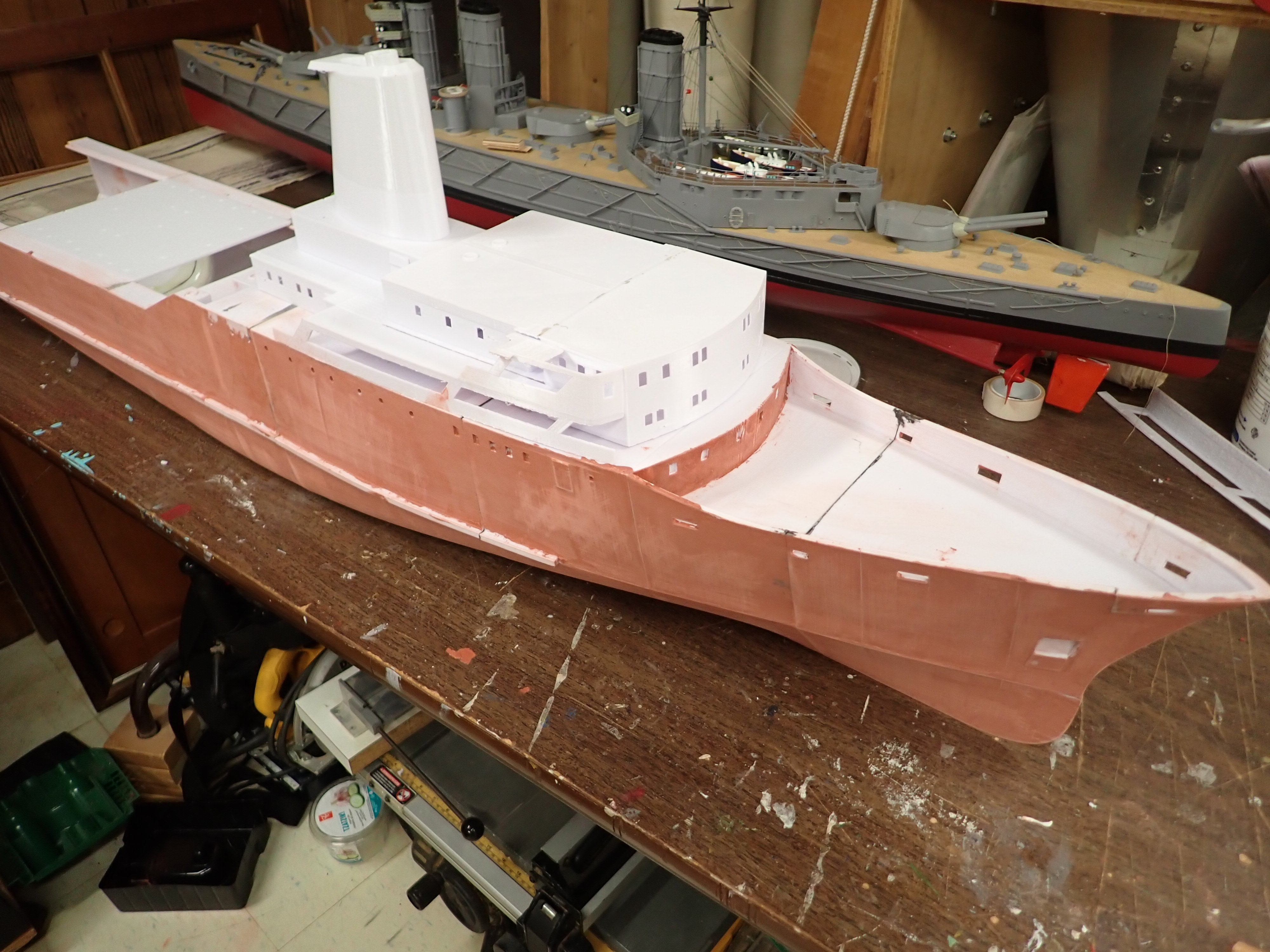
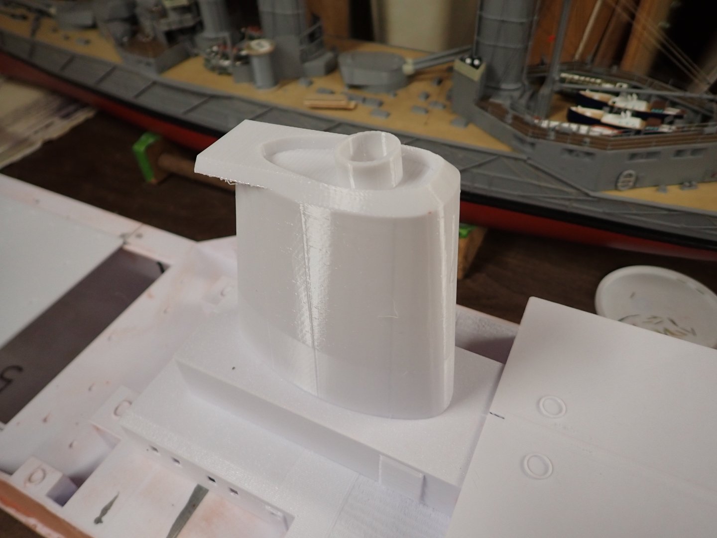
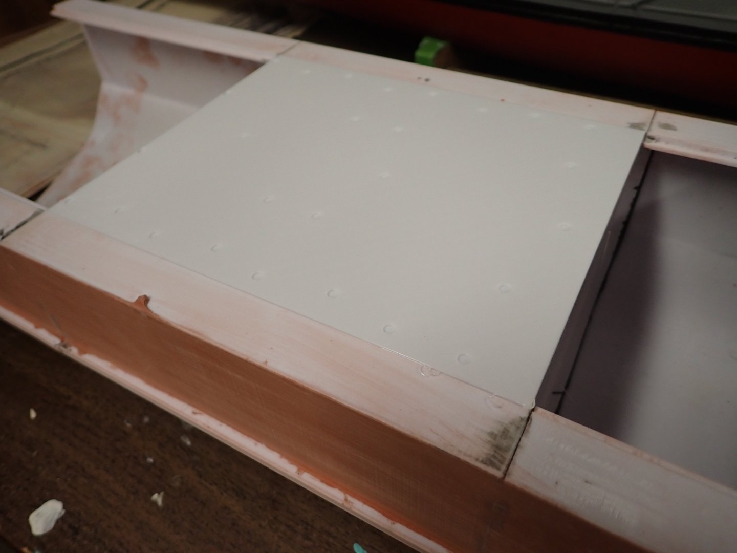
Still haven't attached stern because awaiting prop and rudder hardware. Thought I'd see what the bondo glazing putty is like to work with. Spreads easily, sands easily, reeks to high heaven! A mask and ventilation are musts! It's rather like mudding drywall - use sparingly or you'll end having to sand 2/3 of it back off. Got one quick undiluted coat on and sanded a bit. Next I will try brushing diluted with acetone which should be far faster. Also printed the funnel and a section of the upper vehicle deck. The first funnel print was too flimsy for my liking (it's mostly hollow) so I added some vertical interior ribs up the sides and re-printed. Much better! Also made the final "stack pipe" hollow through to the interior to provide some air venting on warm days. The funnel will be my handle by which to remove some of the superstructure for interior access or at least visibility. See below. Lastly, looking at the photos @Javelin sent me above, I see the 3d file designer has the bollards all wrong; will be printing proper ones when I get there. Will need to modify the bow's bulwark openings for them....would have been so much simpler to modify the 3d file before printing that hull section, had I known! LATER EDIT: Now having seen the GA drawing, thanks to Javelin (see below), I realize the 3d designer has the bollards correct; he just omitted the fairleads at the bulwark openings. Ian

- 24 replies
-
- 3
-
-
- ferry
- Europic Ferry
- (and 1 more)
-
Looks good , Bill! I have a question for you - what specific LEDs are you using for all this illumination? Asking because I have started a project for which I want illumination too. 😁
-
@Javelin; thanks a million! Great information! Now it's making sense to me too. I didn't realize there were THREE vehicle decks .... thought there were just the upper and "main" which I thought of as "lower". Makes me wonder how much room there was to run the prop shafts astern from the engine room. Hmmmm ... wonder if I can animate both stern doors? The stern print has a few inches of "main" vehicle deck inside, on which I could park a few vehicles too. But its lower edge is quite close to the waterline. 🤔
- 24 replies
-
- 3
-
-
- ferry
- Europic Ferry
- (and 1 more)
-
John; maybe I missed this, but what LEDs are you using? I took a look just today for my new build and am bamboozled by the multitudes of products on offer......
-
Thanks Brad! On both mastheads or just the foremast which is at the superstructure? Ian
- 24 replies
-
- 2
-
-
- ferry
- Europic Ferry
- (and 1 more)
-
Brad, I wondered about that. I'm not clear about the extent of the rear ramp; the design has large hinges molded in to attach the ramp with a metal rod but the hinges are at the level of the upper vehicle deck. Apparently the lower vehicle deck was accessed by a hydraulic ramp from the upper deck and as such most of the large opening in the hull stern piece is to be glued in; designer left it for access to install the rudder hardware....I might modify to have some more of the vehicle deck removable to maintain better access to this in future. I wish I had more info on the arrangement........how could they fill the lower vehicle deck when the ramp must come down to it when activated? How did they turn vehicles around on board to face the rear exit when landing? I read one source which mentioned the dock having ramps (plural) in place for vehicle access.....was there a door for the lower vehicle deck which the 3d designer didn't know about? (on the other hand another source claimed she had a forward door which she definitely could not else cars would be driving through the engine room and superstructure). Wish I had clearer info but there's not a lot that I can find. By the way Brad, perhaps you can advise on a couple of other topics. Her foremast has two small platforms on the forward edge which the 3d design leaves just as flat surfaces. I see in pictures in my first post that the upper one is a radar (would be neat if I could have it rotate up there but I can't see how.....ideas?) but what might the lower be? I can't make it out. Also - navigation lights. I need to order LEDs for interior illumination and for these. I think I see port/starboard lights near the bridge; would there be a white at the top of each mast? Something near the stern since all the superstructure is forward? Any info appreciated. Ian
- 24 replies
-
- 3
-
-
- ferry
- Europic Ferry
- (and 1 more)
-
HMS Victory by ECK - OcCre - 1/87
Ian_Grant replied to ECK's topic in - Kit build logs for subjects built from 1751 - 1800
That work would have taken me four or five days, how do you do it? -
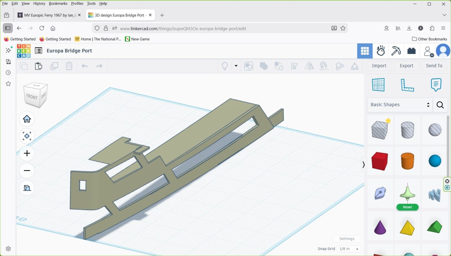
Update: Suddenly I have three empty spools and one nearly so......printed the two "bridge sides" and the funnel. I didn't like how the "sides" turned out so I will be printing in another orientation. They're a bit of a weird shape ... curved edges everywhere ... and I picked a less than optimal orientation apparently.
- 24 replies
-
- 3
-
-
- ferry
- Europic Ferry
- (and 1 more)
-
Hi Kevin, I see you found this......the seams lined up very well with the exception of 3-4 as mentioned above. The designer's instructions warn to be careful about gluing the hull together in a straight line rather than just pressing the seams together as hard as you can. You have to heed this and "tweak" them slightly to achieve a straight keel, which can leave an uneven though small gap. In any case it will all be covered in Bondo putty to cover printing rippling.
- 24 replies
-
- 2
-
-
- ferry
- Europic Ferry
- (and 1 more)
-
I bought four reels at the start. Two are empty, one mostly so, one still has quite a bit. I bought a fifth upon realizing more would be needed, especially as I've printed three versions now of the forward superstructure and two of the aft. Keep thinking of improvements. After the superstructure and funnel it will just be fittings, small potatoes. I ordered two brass rudders, two 4mm prop shafts and tubes, and 40mm counter-rotating 4-bladed brass props for her.
- 24 replies
-
- 2
-
-
- ferry
- Europic Ferry
- (and 1 more)
-
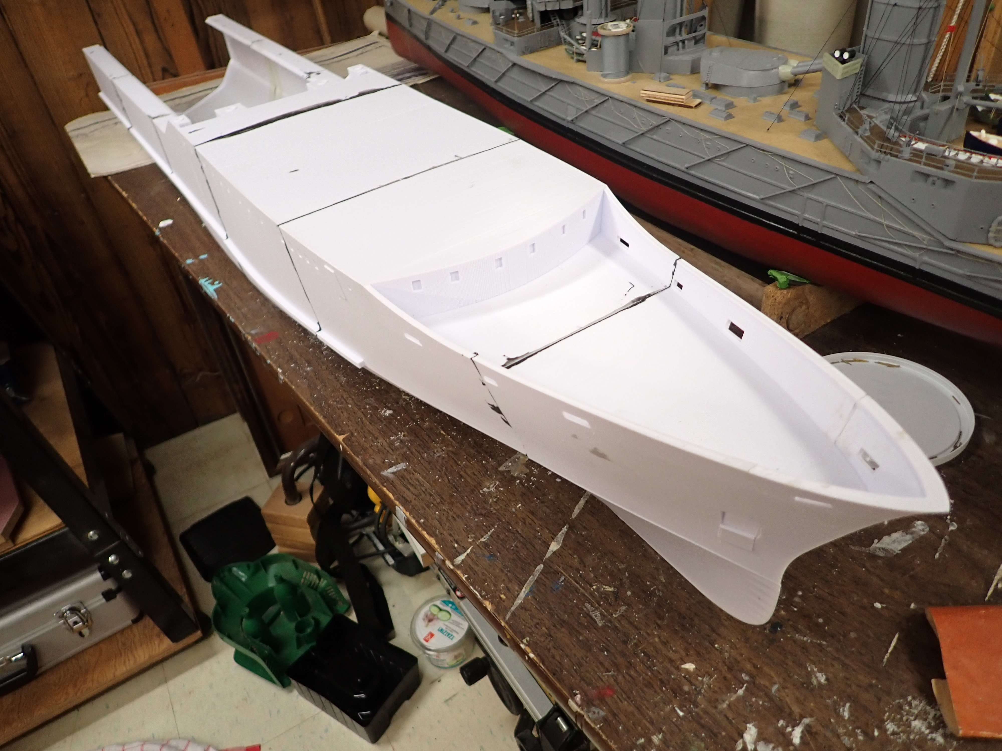
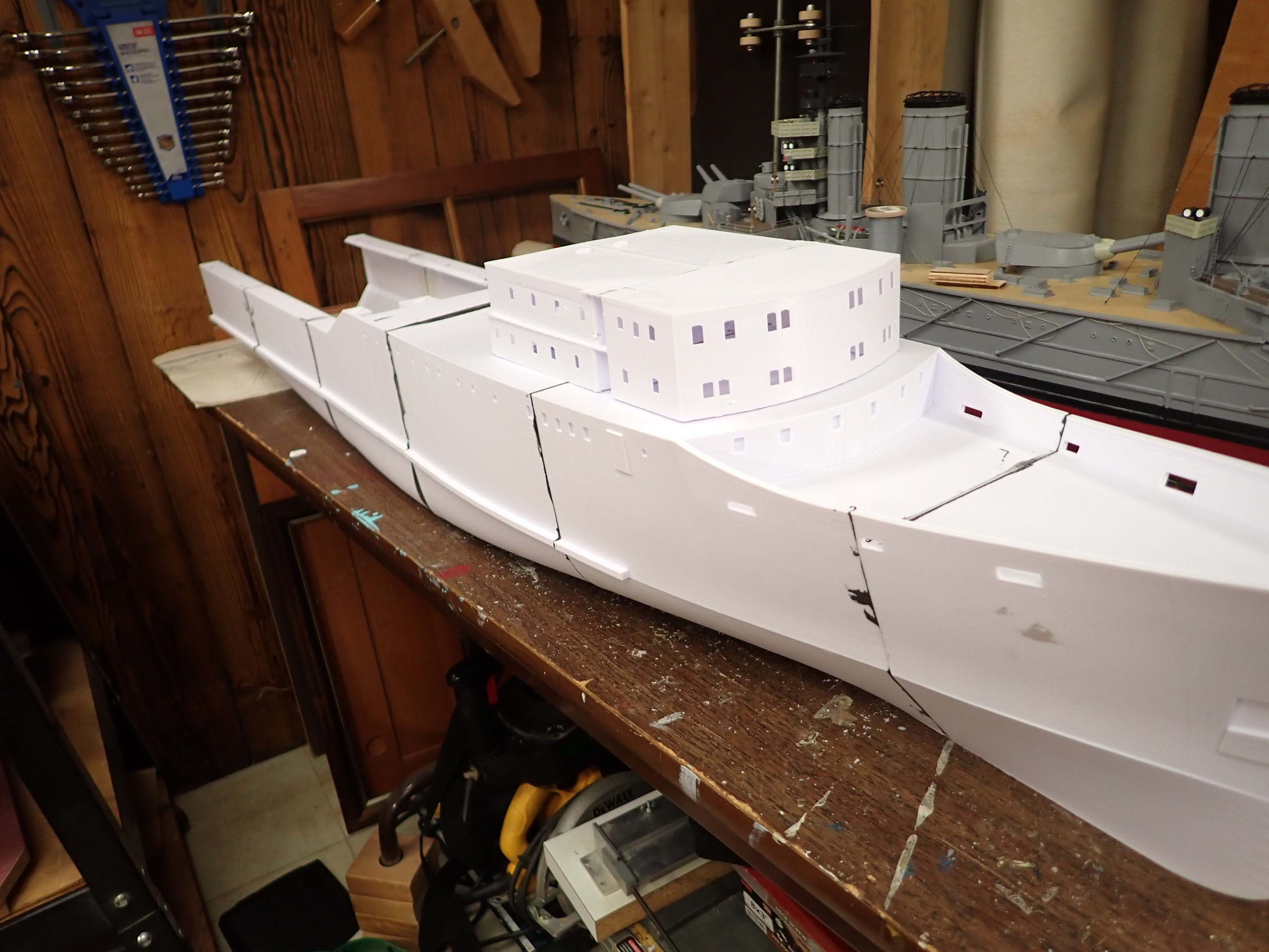
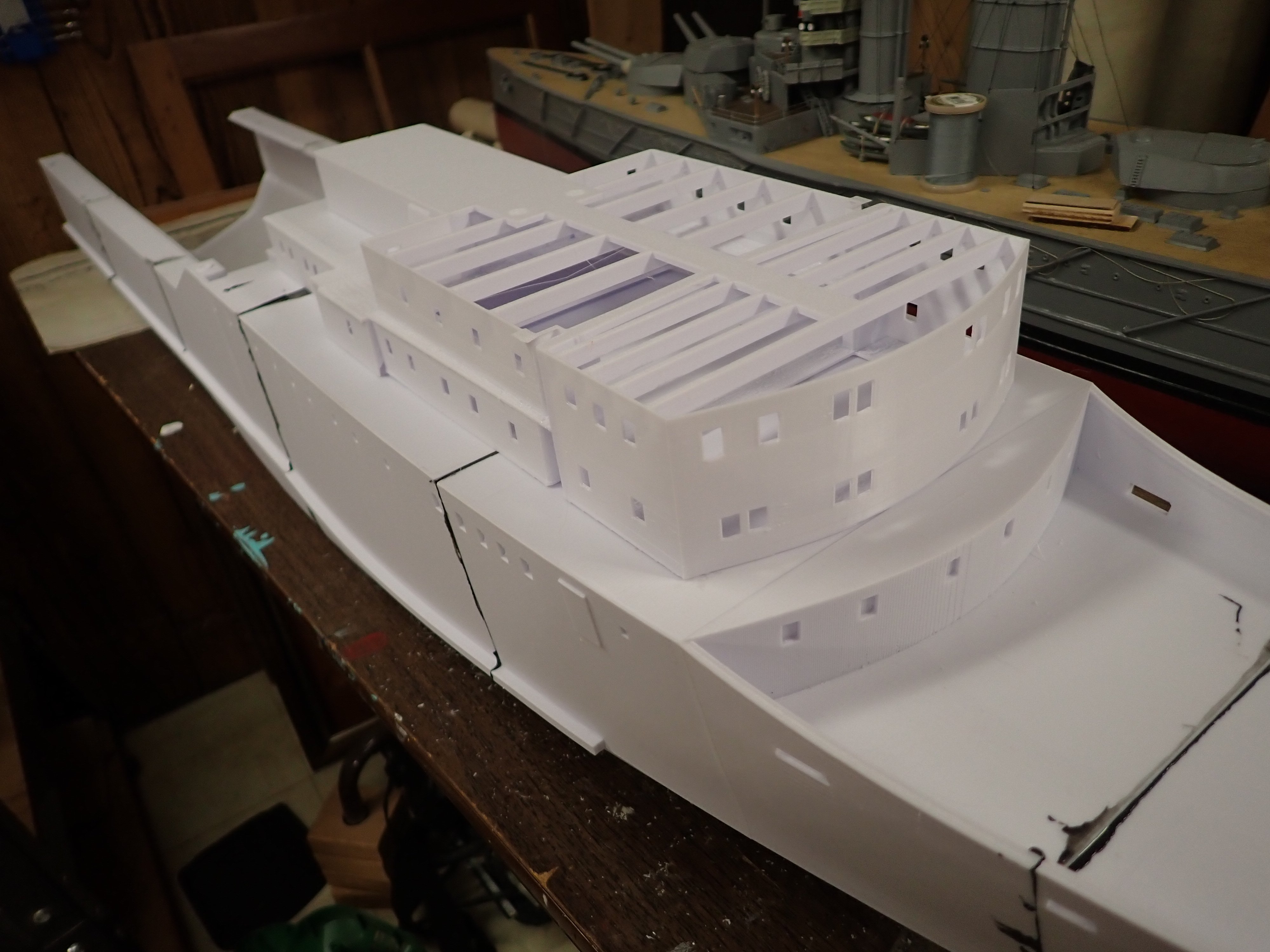
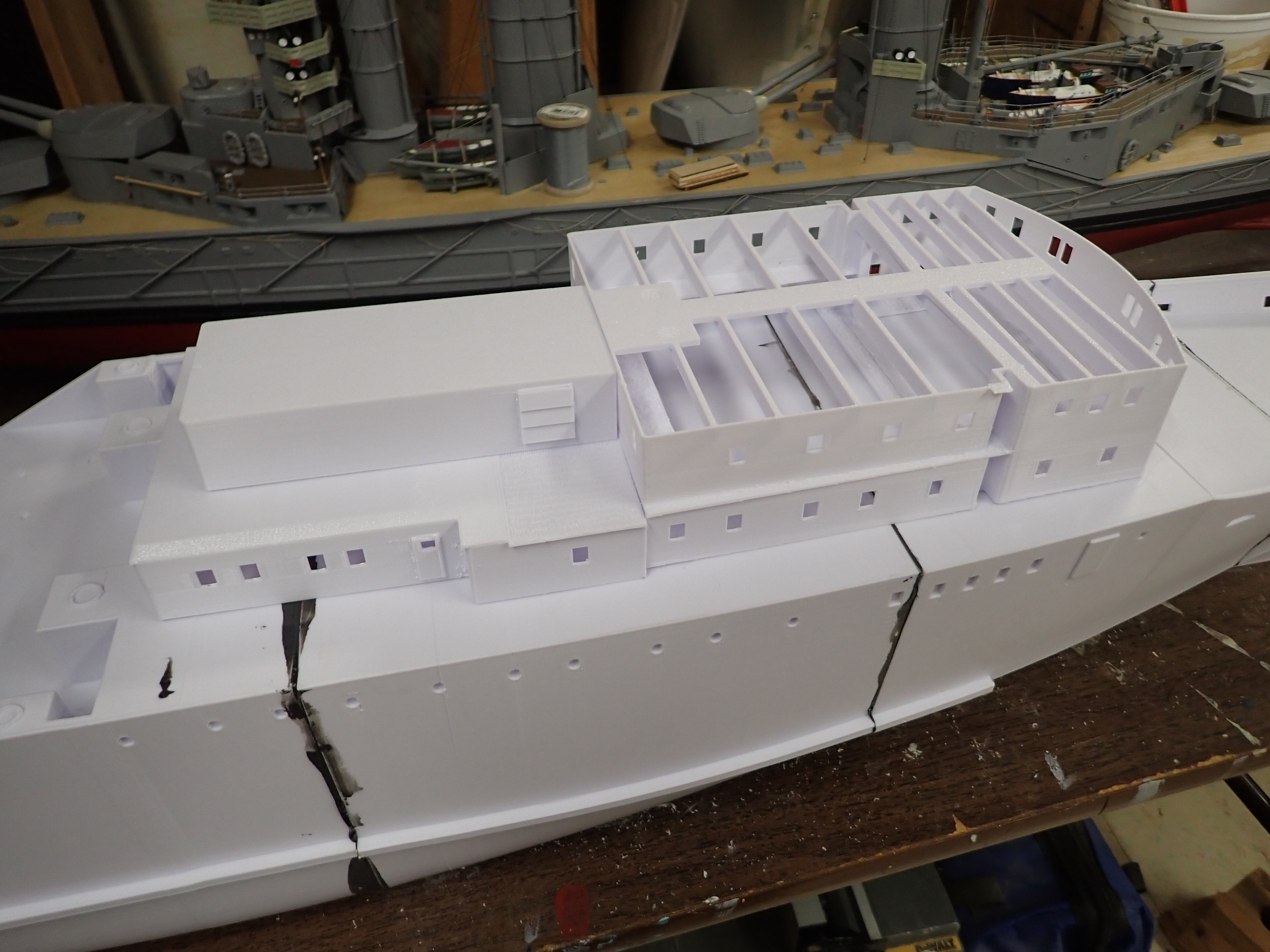
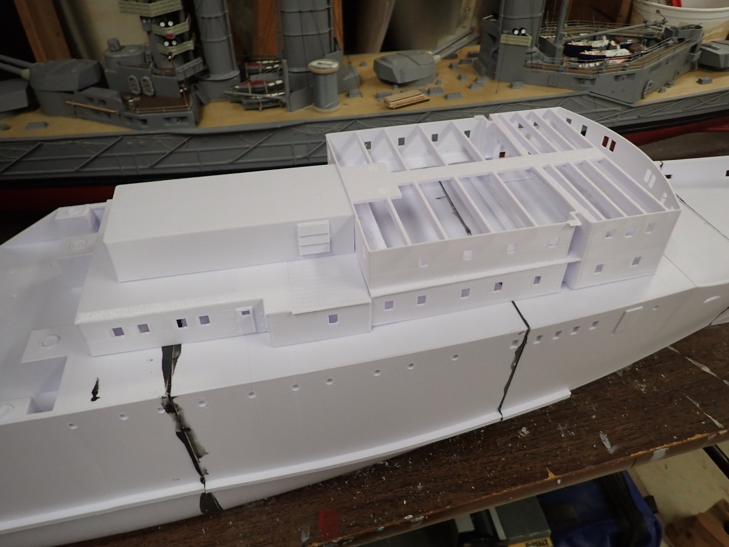
First six hull sections epoxied together, with so far five reinforced internally with fiberglass cloth seam tape and epoxy resin. Lesson learned: when printing large hollow pieces with some large flat surfaces, add some "beams" to hold the flat surface, well, flat. Hull section #3, the 22-hour print, warped as it cooled, making its flat top completely concave. This in turn pulled the corners in slightly as it cooled, warping the joint edges. It was a bit of a bi**h getting section #4 to join to it with proper alignment. I then printed the first two pieces of superstructure, as shown here: I mentioned before that I want to illuminate this model. I was worried about light leakage at the deck joint so decided to re-print it without the roof. While I was at it I joined the two files to print in one piece. I add ceiling "joists" to hold it all straight until glued to deck, planning to then put small strips along the inside deck joints and paint the insides until "light tight". Placing it on the hull I realized that I'd have a hard time getting my fingers in with the "joists" in the way, so the plan now is to glue to deck, cut off the joists, install LEDs/paint inside, then print the ceiling with added beams on the bottom to stiffen it. I printed the aft superstructure too, but I split the single section into an upper and lower section, again to facilitate LED installation and test. St Still pondering creating an access opening near the front. It might turn out be more of visual access than physical, too small for my hand but at least allowing me to see my hand and what it's doing when thrust forward inside the hull from the car deck access. This second print of the forward superstructure might not be the final version..... Looking ahead to railings, the files include railings to print in plastic but I might prefer to build in brass in which case I'll need to thicken the decks in the necessary areas to allow secure gluing of brass stanchions. Printed railings sound fragile, but maybe I'll be surprised. Another lesson; I dropped it on the basement floor and cracked up the top of the stem above the deck. Curses! But it was a simple matter to take a copy of the design file for hull section #1 and delete all of it except a portion of the bulwarks near the stem and print the resulting "patch", then cut away a bit more of the broken bulwarks to give clean edges and CA the patch in place. Ian


- 24 replies
-
- 9
-
-

-

-
- ferry
- Europic Ferry
- (and 1 more)
-
Excellent model - immaculate finish! She'll look impressive pond-side and on the water. Very well done! 👍👍👍 Three thumbs up!
- 79 replies
-
- 5
-
-
-
- Nordkap
- Billing Boats
- (and 2 more)
-
Very nice!!! 👍👍(Two thumbs up)
-
Love the draped raincoat and dangling radio mic in the wheelhouse! Great model. 👍
- 45 replies
-
- 3
-
-
-
- Fischkutter
- Laser Creation World
- (and 1 more)
-
HMS Victory by ECK - OcCre - 1/87
Ian_Grant replied to ECK's topic in - Kit build logs for subjects built from 1751 - 1800
You're moving at a fast clip! Nicely done. -
This is the Bondo Spot/Glazing Putty? I saw a prop maker (armour, star wars helmets, etc) on youtube using this as a first coat ONLY on large ridges and grooves, then thinning it with acetone and brushing on to fill smaller grooves and reduce sanding effort/time. I plan to try this on my 3D print hull. I remember seeing the type 26 file on cgtrader. There's also a very nice RC minesweeper model which tempted me "bigly" (a la Trump).............
- 60 replies
-
- 2
-
-
- Type 26
- City Class
- (and 2 more)
-
HMS Victory by ECK - OcCre - 1/87
Ian_Grant replied to ECK's topic in - Kit build logs for subjects built from 1751 - 1800
Very very nice! -
I do know that the 4-masted barque Admiral Karpfanger ex L'Avenir sent a radio message in Nov 1939 saying all was well as she approached Cape Horn, then was never heard from again, so the radios had good range.
-
Happy New Year, Bill!