Ian_Grant
-
Posts
2,100 -
Joined
-
Last visited
Content Type
Profiles
Forums
Gallery
Events
Everything posted by Ian_Grant
-
 It's common to buy small beads, maybe 15/0 ?? at your scale, with which to make parrals. It's easy to thread through them but slightly more difficult to make the little ribs between the beads.
- 178 replies
-
- 1
-

-
- Flying Cloud
- Mamoli
- (and 1 more)
-
Looks great! Did you have these decals custom-made?
-
Nice work. Those lower yard trusses are detailed - are they a kit part or did you fabricate them?
-
Glen, you keep raising the bar with each build!! This is truly amazing, and I really like the wavy flow of the bottle itself, too. Very, very well done!
- 156 replies
-
- 6
-
-

-
- Queen Annes Revenge
- bottle
- (and 1 more)
-
Looks ah-ma-zing John!
-
When I left home after university to start work in another town, I came back at Christmas to find that all my plastic model airplanes and ships had disappeared except my Revell 1/100 Cutty Sark and Constitution. Thankfully, they kept all my wood RC boats which I am now in the process of refurbishing/rebuilding, one by one. I tell myself I won't trash my kids' stuff but the basement is getting pretty crowded with furniture for future homes, etc. 🤔
-
HMS Victory by ECK - OcCre - 1/87
Ian_Grant replied to ECK's topic in - Kit build logs for subjects built from 1751 - 1800
Great job! And you're moving at breakneck speed too.....😏👍 🤙 -
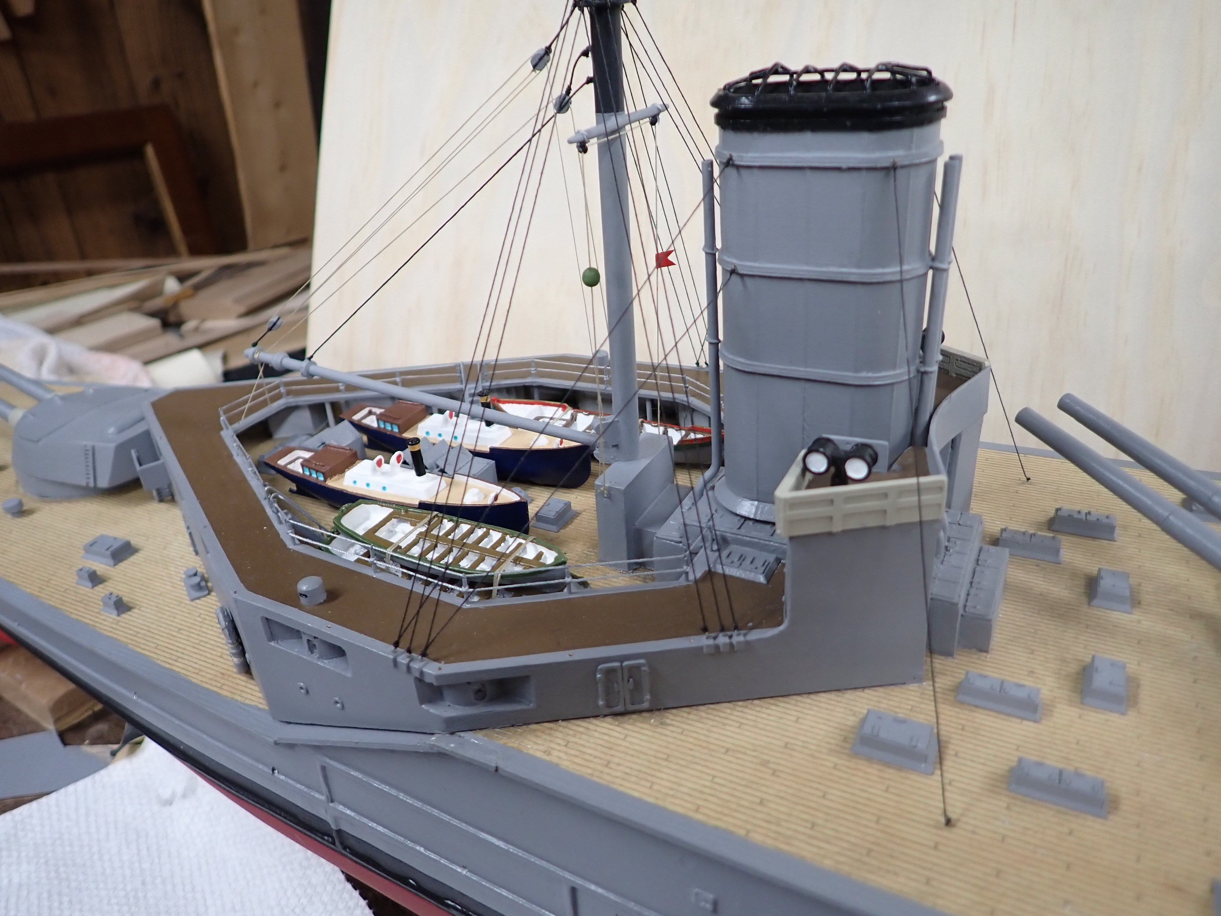
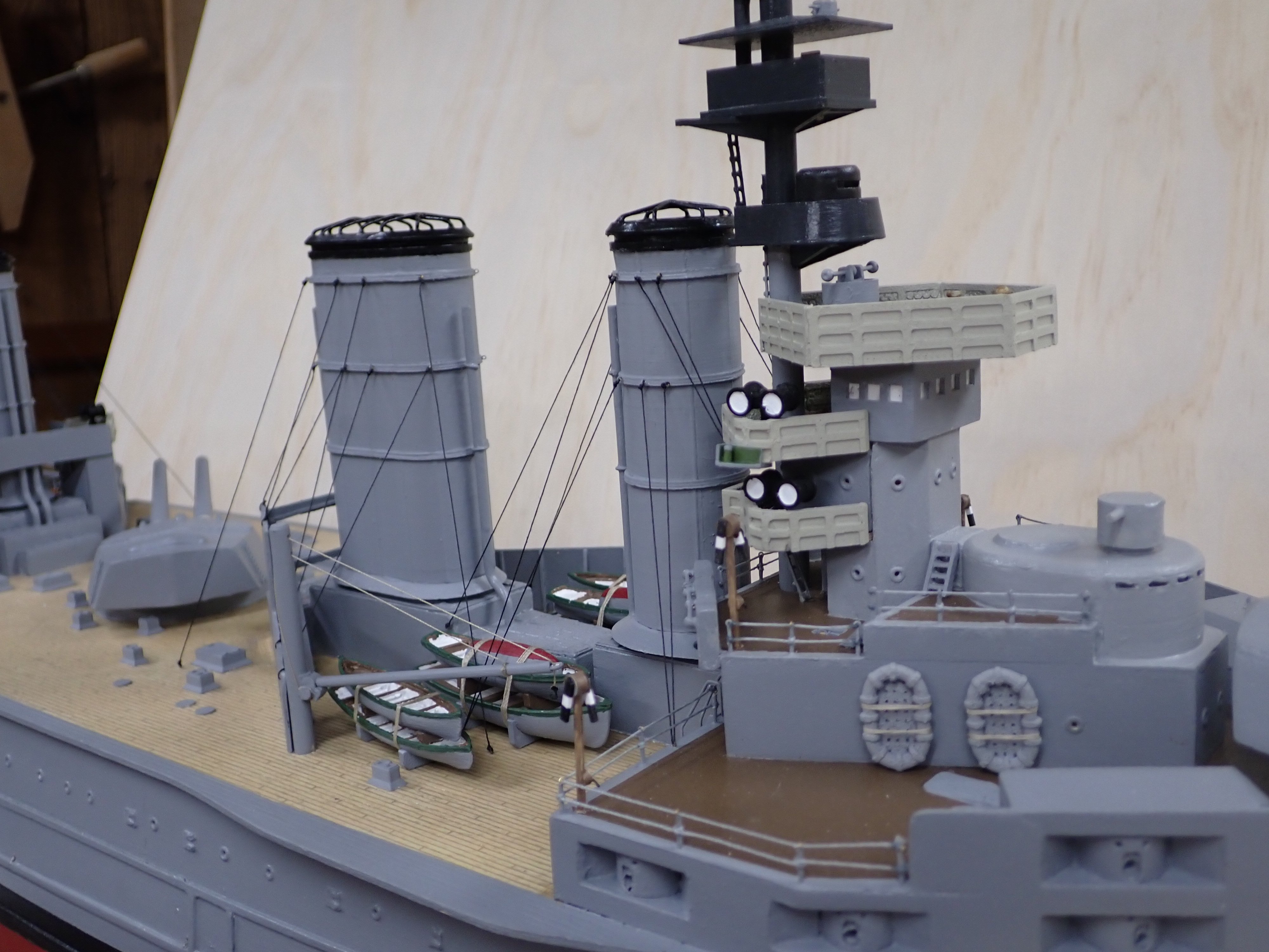
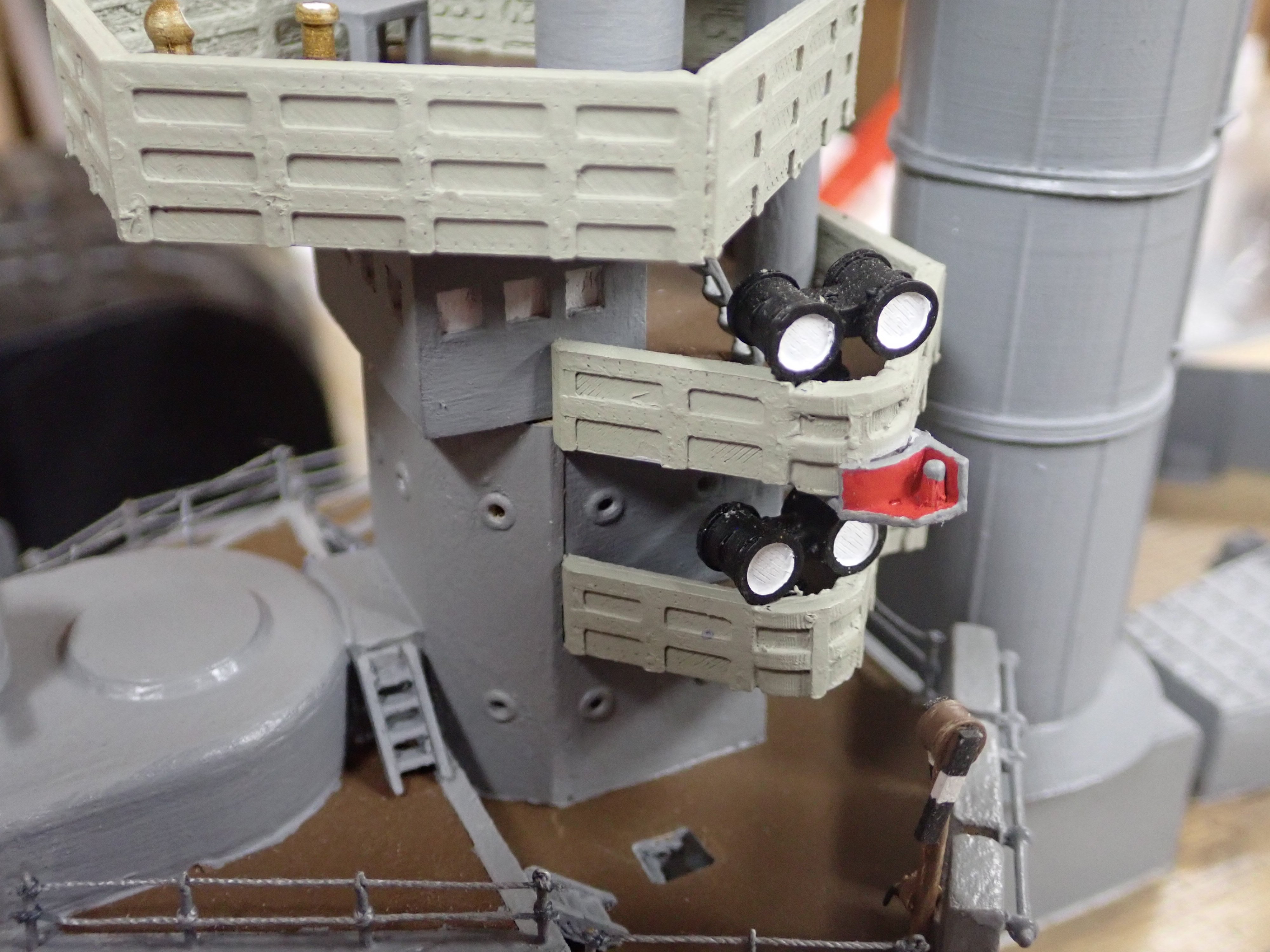
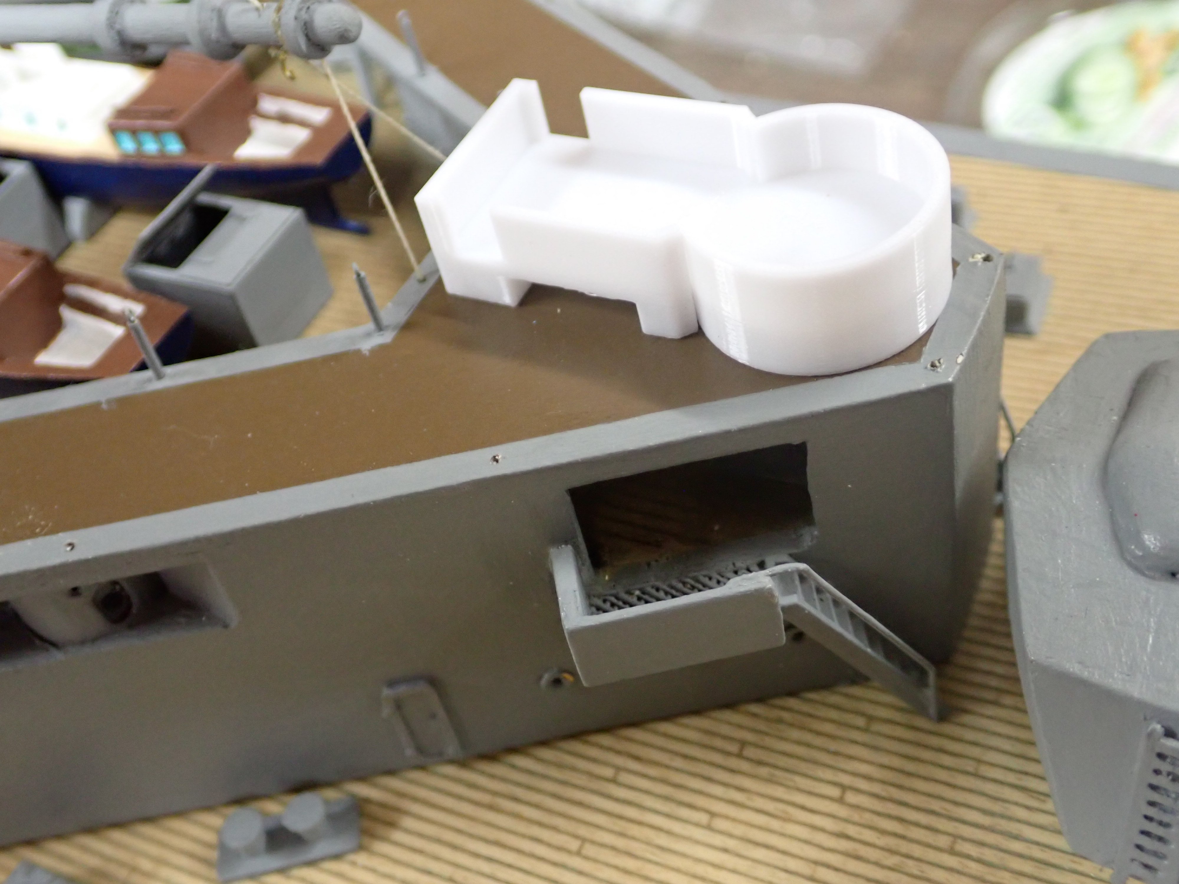
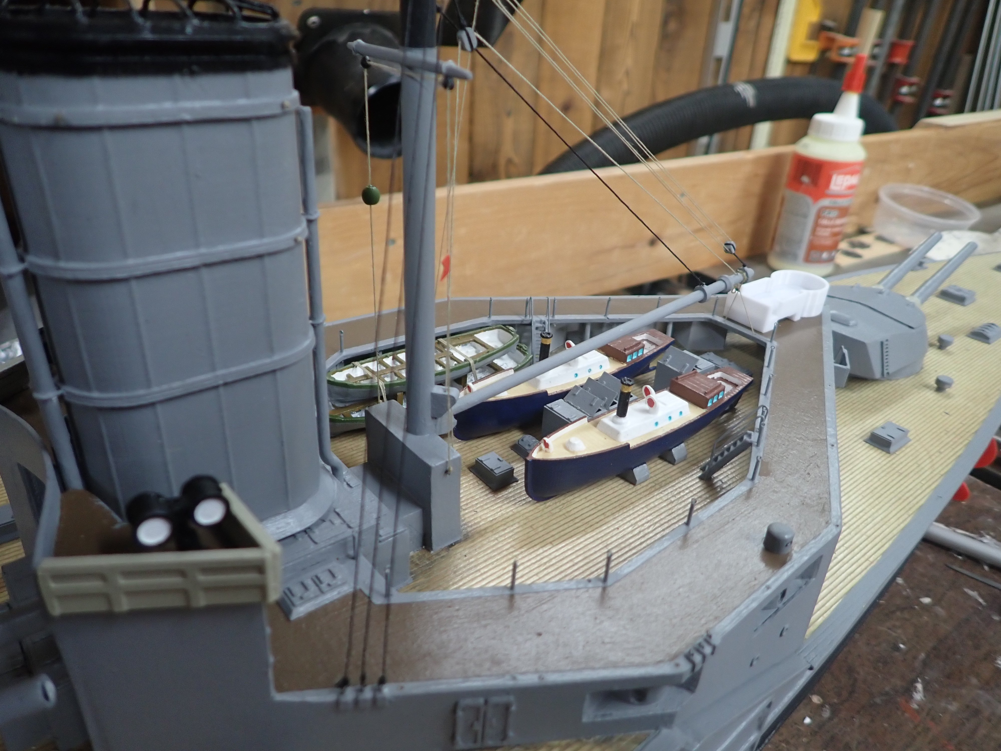
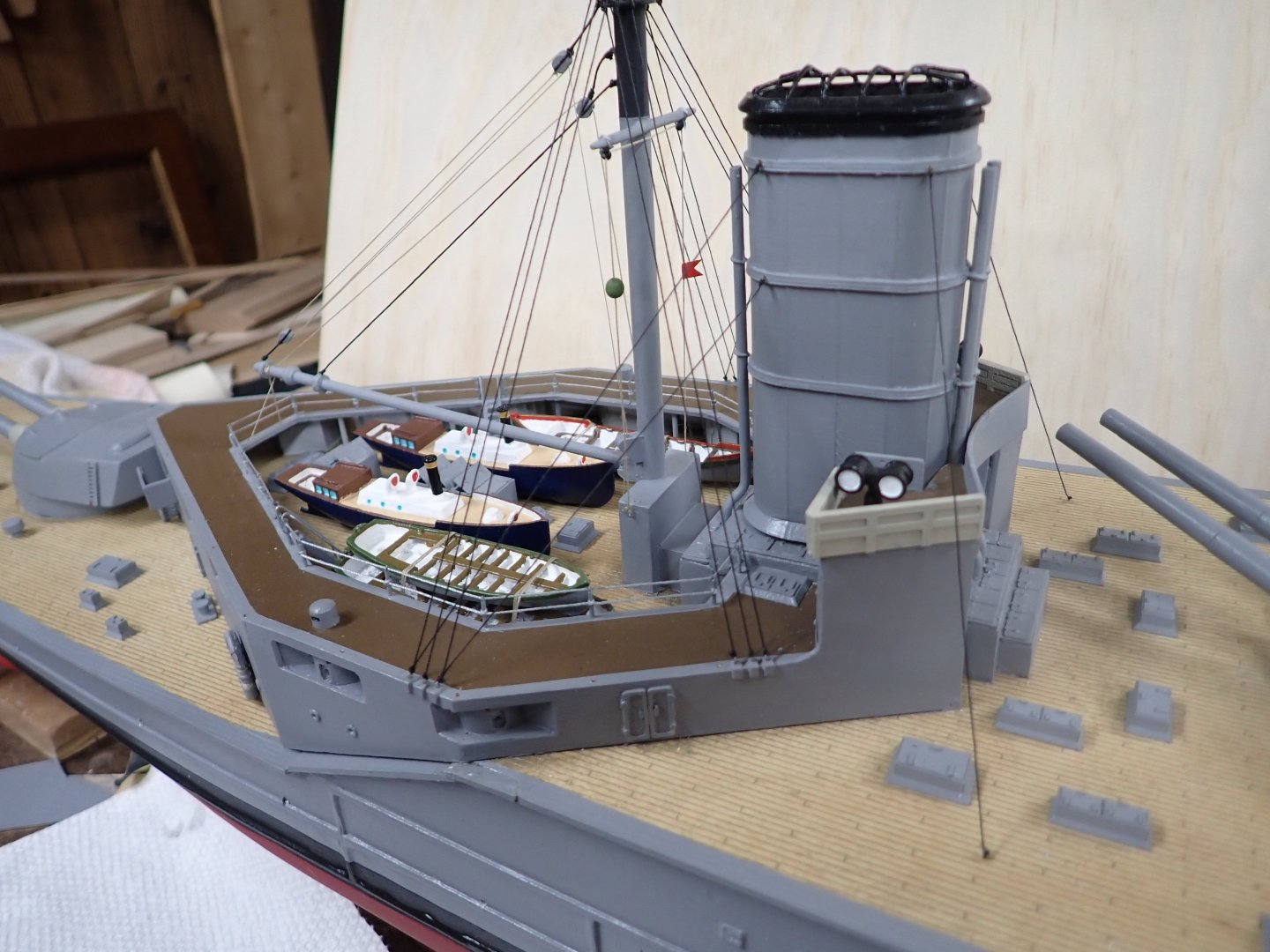
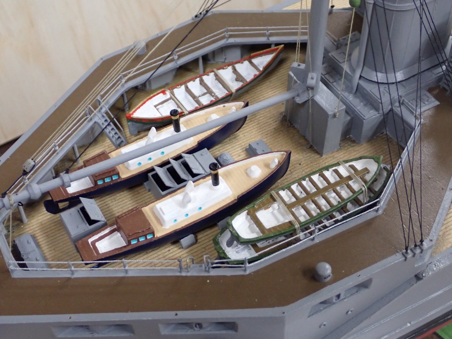
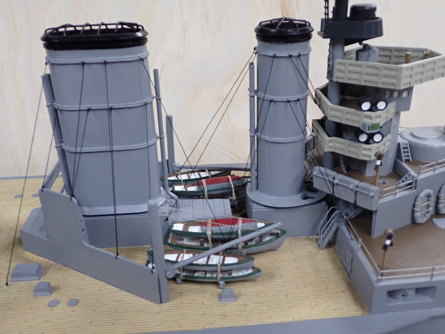
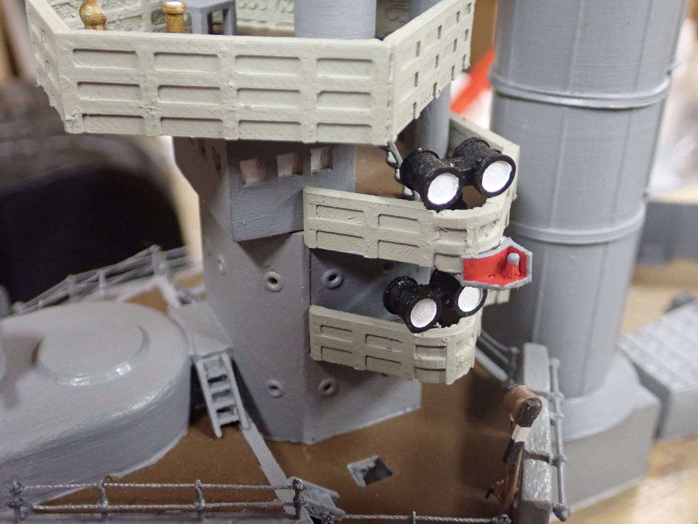
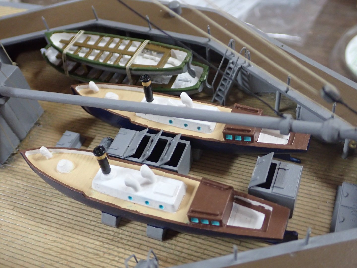
Thought I needed to post a "proof of life" message, so here we are. Worked on the rest of the ship's boats; ten of them in two stacks of three and two stacks of two. It took me days and days to find suitable printable hulls, break off the print supports under seats etc, and paint them. They printed with very nice floor boards etc but many of them were ripped up in the process of removing the supports. Fortunately you can't see inside the lower boats in the stacks. For the stacks of two, I needed a hull with two pointy ends for the upper boats; I used a "Titanic Lifeboat" file for the them because they printed cleanly. For the stacks of three, I inverted the 16ft dinghies on top because the tiny interior details were too delicate to clean up neatly. These dinghies are 1.1" long. Also added the admiral's barge (albeit as a whaler because that printed better) all painted up fancy. Don't know if they kept it fancy in wartime but anyway.............. Boats in the aft well deck. Still need to rig the outer railing on the shelter deck. Barge has red/gold trim. Rigging on the aft superstructure. Boats at the forward superstructure. Tiny dinghies are painted red on bottom. Fore and main funnel bracing wires complete on the starboard side; not started on port side. Boat cranes not fixed in position yet. You can just see a couple of the Carley rafts I drew and printed. By the way, why were bracing wires needed for funnels on these ships but not on later ships? Welding instead of riveting? View of forward superstructure. Next up? Let's see.....foremast stays and many signal halyards; radio "aerials"; two tiny sounding machines and booms for the fwd shelter deck; two hotchkiss guns aft; main deck railings (🤔); brailed torpedo net and booms. Also I need to investigate the app for programming the sound effects board. No rush now as the RC club sailing season has pretty much ended unless we get another warm Wednesday. I want to finish this and complete my "Preussen" model this winter.

- 235 replies
-
- 12
-
-
John, You're doing great work creating these wheel parts. Since they will all be painted bright orange anyway, if you know anyone with a laser cutter or 3d printer they could be done to perfection in seconds/minutes. May be heresy, I know, but it would give you more time to devote to the cabins etc. and complete the beautiful model earlier. 🤙
-
Yes, they were one of my favourite species during our Galapagos tour. We were walking on the designated path on an island where they breed and females were sitting on eggs on the ground everywhere, even sometimes in the middle of the path where we had to tiptoe around them. Plus they were busy doing their mating ritual which involves showing off their blue feet.
- 156 replies
-
- 4
-
-

-
- Queen Annes Revenge
- bottle
- (and 1 more)
-
...even as far away as the Galapagos...........

- 156 replies
-
- 7
-

-
- Queen Annes Revenge
- bottle
- (and 1 more)
-
Good first build; you're a braver man than me. I've never tried planking a hull. Just a note about the blocks in your mast picture: it looks like the two upper blocks are the wrong way round. By this I mean the single holes should be at the other end. Imagine that the rope passing through has to go around the disc-shaped sheave (a pulley) within the block; whichever direction the rope comes from it must enter the block at the furthest end in order to use the pulley. Enjoy your rigging! Ian
-
As I recall, flemish horses were present on any yard carrying a sail which had reef bands. A crew member had to be at the very very end of the yardarm to haul the end of the reef band taut and attach to a fixture at yardarm end. I believe this was called "passing the ear-ring". The regular footrope is too near the yard (in the sense of height to the yard from the rope) for this seaman to safely stand. The Flemish horse droops lower to provide this. I haven't looked to add to this response, but there are pictures of seamen even sitting astride the yardarm end to haul the band taught. That's what I recall anyway; I should consult Harland.
- 178 replies
-
- 2
-
-
- Flying Cloud
- Mamoli
- (and 1 more)
-
That's ok, we'll wait (sound of chair scraping). (sound of feet tapping). "Umm, are you back yet?" (sound of feet tapping).
-
Nice hull Bill! Also - I hereby induct you as an honorary electronics engineer! Your iron ring is on its way (well, not really since it's a Canadian thing!).
-
Hi Glen - another awesome build! Just got back from vacation and saw this thanks to your mention of me. 😏 Probably moot now, but when I read about your new idea of lit flames I thought of this build I had admired before:
- 156 replies
-
- 6
-
-
-
- Queen Annes Revenge
- bottle
- (and 1 more)
-
A little more progress. I've had Lion on the water at three club pond sails. Very relaxing and it's fun to chat to the same 5 or 6 other guys who show up at the park. This week there was a boy hovering around interested; gave him a shot at steering her around. Among other things in a constant flow of talk, he remarked, "You must be the youngest one here". HaHa. Says something about the hobby. I added the port and starboard navigation lights, at the level of the charthouse deck. Still need to make white ones for the foremast/mainmast. I started working on the mainmast stays, then realized they would get in the way of drilling holes and adding stanchions for the aft shelter deck railings (which I have been procastinating about for weeks!). I now have the stanchions for the inner railings made, glued in, and painted grey. I decided to add the boats in the aft well deck before the railing threads were in the way. I spent a l-o-n-g time painting these boats; even then in the end I decided to forego painting bootstripes and red u/w hull on the steam pinnaces since it seemed too much more taping etc for results not all that visible. Here we see the two steam pinnaces, and two stacked boats. The port side will contain the "admiral's launch" beside the pinnace. I can't find a suitable, cheap, 3D file so I'm going to use a whaler hull which printed nicely. I added trailboards at bow and stern and will paint up all fancy for the admiral's use. Don't know whether they slapped grey paint all over these boats in wartime or not. Also visible in the pic are the "green ball" and "red flag" of the helm indicator for ships following when in line ahead, and the inner rail stanchions. I added handrails to the two ladders, from 0.5mm brass rod. I printed a prototype for the Hotchkiss gun emplacements; she carried two on the aft end of the shelter deck according to Norman A. Ough's drawing. God knows how I will make tiny Hotchkiss guns.....TBD. Last, I finally glued on the forecastle breakwater which also has been sitting around painted and ready for weeks. I ordered and have received (just this week) a sound board with USB programming cable and speakers. It's a great little board which plugs directly into an RC Receiver channel (taking power from it too), specifically the channel which has a 3-position switch on the Transmitter (commonly used by pilots for full flaps/half flaps/flaps up). In this case you click it up say "n" times, then click it down once. "n" is the number of the sound track you want to play (board can store many), and clicking it down triggers the audio play. The board can store almost half an hour total of sound. I have WAV files for bosun's call, klaxon, and the old-time steam driven triple-note whistle. Club members suggest "God Save the King" (this is 1916!) and heavy gun fire to go with the rotating turrets. I'd also like to play a voice calling "battle stations" but I have not yet found it with a British accent, only American.🙄 Should be fun!! For example, other club members with model Corvettes have sonar pinging, sonar pinging with a return echo from a sub, gunfire, depth charges exploding, "action station" calls (no Brit accent but they're models of Canadian corvettes). We're starting our trip the day after tomorrow so it will be a while for the next update. Thanks for following!


- 235 replies
-
- 12
-
-
-
Good idea. I did the same thing for my Heller Victory.
-
Beautiful job so far! Is having two adjacent capstans historically accurate though?
-
Michael, obviously your idea of fun differs from mine. 😁 What was it Andersen said?......"The sprit topmast backstay was one of the places where the early 17th century rigger let himself go." Just kidding; I look forward to seeing it in the "flesh". Ian
-
I used a bead then wrapped thread around it. Still doesn't give the woven effect though.
- 341 replies
-
- 1
-
-
- Sophie
- Vanguard Models
- (and 1 more)
-
Simply gorgeous, Siggi !!!
-
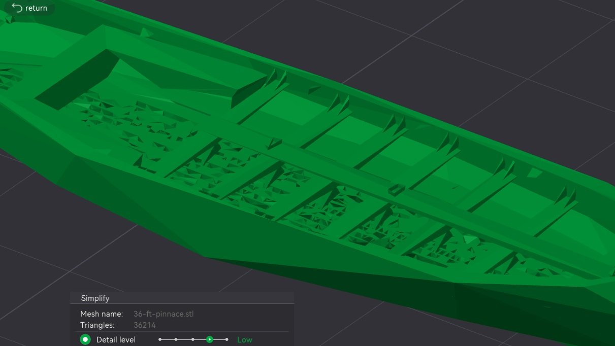
You can contact designers via Yeggi/Thingiverse. I noticed that the steam pinnace design, which prints with a perfect hull, was by one designer whereas the other boats were by a second designer. I had not noticed in my excited downloading. The second designer's intro notes that he is a "beginner" and warns not to expect perfect designs. Indeed, the images on Thingiverse show the same hull scalloping as I see in Bambu Studio. Far be it from me to chide him about this; he has done a great job on the interior and has far more 3D skill than I. So it's back to sprucing them up by myself, somehow. Thank you for the suggestion, Kevin! And indeed for this trip down 3D-file-world!
-
@Kevin-the-lubber, here is an update. Bambu Studio does indeed have a simplify function, but it appears to default to "Very High" detail level which is what the screen shot above depicts, believe it or not. When I lower the detail level not only does the hull exterior get even worse, but the interior details (floor gratings etc) start to disintegrate too. Here's a screen capture of "Low" detail level. Now that's an ugly hull!!