Ian_Grant
-
Posts
2,156 -
Joined
-
Last visited
Content Type
Profiles
Forums
Gallery
Events
Everything posted by Ian_Grant
-
 Hi Bill .... what I have seen done is to make the water surface from a sheet of lexan with the waterline profile cut out of it; make your wavelets on it and colour it; have clear sides on the stand so the viewer can see the ship u/w too. Some transparent blocks of lexan can be used to support the ship so the "sea" doesn't sag.
 -
Well done! But to me the biggest problem with these shroud jigs is the absence of all the served shroud pair centres stacked up the masthead. I suppose one could CA the shroud ends at the base of the masthead (at about the bolster) then "serve" part of the masthead to make it look more like the shrouds are properly constructed. Having said that, in the "Victory" kit the lower mastheads above the bolster are separate parts from the remainder of the masts. If memory serves, the shroud jig for this kit has a spot for the masthead to attach and then you really can wrap and serve the shroud pairs around the masthead, although Heller still shows the wrong way of seizing them together.
-
I've been really impressed with some of these card builds on the site; first Chris Coyle's airplanes and now ships such as yours (which looks great by the way). They're amazing when done well. I must try one someday.......
- 63 replies
-
- 4
-

-
- card
- Revenue Cutter
- (and 2 more)
-
Mon Dieu, monsieur! You are going to the nth degree in details Malcolm. Congratulations and if you keep this up your ship will be magnifique!
-
Man, I wouldn't want to have to (carefully) dust your outstanding model ... ☺️
-
I really like the look of your deck Malcolm. And your quarterdeck rail netting... I take it that's your new stuff, compared to the bulwark netting? Like the coat of arms too.
-
Steven, there's also "Albion Alloys" in the UK which similar to K&S makes brass/aluminium tube and rod down to micro sizes. Last time I needed some 1/32in DIA tubing I obtained it from Albion because K&S would only sell me in large paks, not onesies and twosies. Albion may be in your country too, being British.
- 110 replies
-
- 5
-
-
- Paddlewheeler
- Ballarat
- (and 3 more)
-
Hello from Perth, Ontario - On to Victory!
Ian_Grant replied to Malcolm Brown's topic in New member Introductions
Watch out for cyclists - it could be me. 😏 It is a nice road especially nearer the Narrows end. Remember when it was mostly unpaved from Stanleyville to the Narrows? I remember once coming across a couple whose car had slid into the very sandy ditch at the side. Hopeless - call a tow truck. Geez that was a long time ago.- 31 replies
-
- 2
-
-
- Victory 1:100
- Heller
- (and 1 more)
-
Not at all; I just remember the problems I encountered with the kit, and what I did to get around them. Photos trigger the nightmares again. 😉 By the way Malcolm, don't forget about the extra eyebolts at the mast feet for the truss pendants, like we talked about during your visit.
-
Hello from Perth, Ontario - On to Victory!
Ian_Grant replied to Malcolm Brown's topic in New member Introductions
The two bays .... five minutes by canoe from our place. Look forward to it!- 31 replies
-
- 1
-
-
- Victory 1:100
- Heller
- (and 1 more)
-
Hello from Perth, Ontario - On to Victory!
Ian_Grant replied to Malcolm Brown's topic in New member Introductions
Westport, we have a cottage on Pike Lake near Stanleyville and I often cycle a loop along #10 to Westport then back through Newboro to cross at Narrows Lock and hence back to Stanleyville. The three of us should get together this summer for Cheers, Ian- 31 replies
-
- 2
-
-
- Victory 1:100
- Heller
- (and 1 more)
-
Hello from Perth, Ontario - On to Victory!
Ian_Grant replied to Malcolm Brown's topic in New member Introductions
Mike, I can't believe this; first you help us get plans for "SS Klondike" from the Parks Canada office in the same Whitehorse building where you work, now you tell us you still have a cottage on Pike Lake. Our cottage is also on Pike near Stanleyville! We go in past the playground and cemetery and keep to the left at every intersection to reach our cottage which is just opposite the largest of the group of three islands, on which people used to camp. Our kids called it "Beaver Island" because there was an active beaver lodge on it when we bought the place, only to watch all the big old birch trees on the island be chewed down one by one. What a small world.- 31 replies
-
- 1
-
-
- Victory 1:100
- Heller
- (and 1 more)
-
Absolutely; they towed the boats into battle to reduce flying splinters on board, though they'd be towed astern (check that shot of my print "England Expects" that you included in one of your earlier posts). I've also read that they cast off the boats when battle gets engaged to get them off their tail, but maybe that's a myth. You know how there always seem to be ships' boats rescuing men in the foreground of so many period sea battle paintings? Maybe just artistic composition. You could always rework the sea if you moved the 2nd boat aft.
-
I'm sure it was always her dream to see this ship, Malcolm. HaHa. Welcome to MSW; I am your newest follower. Seeing the photo with the foremast head in place reminds me to recommend: By all means glue the mast heads on, but leave off the cleats on the side faces on fore and main (for the jeer block lashings) and any rigging blocks for now. Reason being is that it is far easier to loop (the served) shroud pairs around a suitably sized drill or dowel for seizing then slip them over the masthead and down, rather than trying to seize each in turn around the masthead. Once the shrouds are in place the mast cap and topmast (and the jeer block cleats) can be added.
-
Excellent! If I ever build her it will be for RC. Wondering if I could have two servos act as the engines, pulling the paddle wheel at 90 degree offsets .... 😜
-
Bill, At anchor with the sails set? Your story could be that the anchor is fouled on the bottom and they are trying to sail it out of the ground (like in the Hornblower story "The Happy Return").
- 1,508 replies
-
- 1
-
-
- Le Soleil Royal
- Heller
- (and 1 more)
-
Thank you all! Much appreciated. I very much enjoy the comments, suggestions, and bantering asides during this build. It will be nice to add the finishing touches to the model and finally reclaim my workshop from this long drawn out project. I have some new kitchen drawers to make. Cheers, Ian
- 536 replies
-
- 3
-
-
- Quadrireme
- radio
- (and 1 more)
-
Here is a short video of the galley in the RC boat club indoor pool session. You can see my hastily-thrown-together transport dolly at the corner of the pool. Embarrassingly, I forgot to put the main deck on at launch hence the return to "shore". No rudders installed as yet hence the pivoting to turn. After a pivot she seems to keep veering in that direction for a while when rowing "straight". Nothing the rudders won't cure. Also note the 6V square lantern battery sticking up a little out of the stern deck. It's too tall to fit under the rear hatch. Still haven't bought the fancy 5-cell NiMH which will fit into the hull. Was planning to put it aft which is quite empty, but the only thing it connects to is my arduino daughter board in the bow. Here I used lamp cord running through the bilge for the connection. I'm not sure what current the giant sweep servos draw when rowing but I plan to insert n ammeter to find out, and to measure the 6V at the battery and at the bow to see if there's a substantial voltage drop. Lamp cord is a pretty big wire. If the drop is substantial the NiMH battery would be best in the bow, if I can fit it in this already crowded location (two sweep servos, Arduino, RC Rcvr, 12V battery). Or use something even bigger than lamp cord. It does look a little odd with the clear sweep of the empty deck. Will be doing something about that shortly.
- 536 replies
-
- 18
-
-

-

-
- Quadrireme
- radio
- (and 1 more)
-
What an unbelievably clean build; no sign of dinged edges or glue marks or sanding marks or the slightest paint flaw! Truly amazing work!
-
No, you're not wrong. 😏 Fortunately she's pretty chill when it comes to home improvements. 👍
- 536 replies
-
- 6
-
-

-
- Quadrireme
- radio
- (and 1 more)
-
Yeah.....storage. I was looking at our laundry room sink recently because it's very slow to drain. I squatted down to remove the trap to clean it out only to find that some clown glued together the entire trap assembly. I'll need to cut the ABS and install a new one...which got me thinking I should replace the sink too since it's disgustingly discoloured...which got me thinking I should re-think the whole sink-countertop layout - which got me thinking I should add some wall cabinets for storage to free up the counter and some shelves - which got me thinking I could move my two 43" RC boats onto a now cleared shelf...which got me thinking I could store the galley where those two boats now sit beside each other (i.e. on a very wide shelf) with oars on and all. To take it to the RC club meeting at the indoor pool today, I attached a piece of plywood and some braces to my two wheeled hand dolly. With the ram removed, the two aluminum dowels at the bow plug into two holes in a wood block attached to the ply, and the keel rests between the two braces. Add a strap at the stern, at the top of the dolly, and it wheels easily around. 🙃🤙👍 Though at 24" wide across the oar tips one must be careful in doorways.
- 536 replies
-
- 5
-
-
-
- Quadrireme
- radio
- (and 1 more)
-
It's true. Back when I guesstimated the weight of hull/mechanisms/battery/electronics I was way over, so the bilge volume is needlessly high. Trials in our pool in September yielded a weight of 22-23 lbs to set it to waterline, which is about 50% lead-shot ballast. It's a real issue trying to get it up the basement stairs and through doorways with oars sticking out both sides, and its 53" LOA. I will need a dolly or a wagon to take it to water.
- 536 replies
-
- 5
-
-
-
- Quadrireme
- radio
- (and 1 more)
-
I'll have to read up on how to video with this camera. No manual was included; do they expect us to carry around 8.5"x11" printouts wherever we go? A pet peeve of mine.
- 536 replies
-
- 3
-
-
- Quadrireme
- radio
- (and 1 more)
-
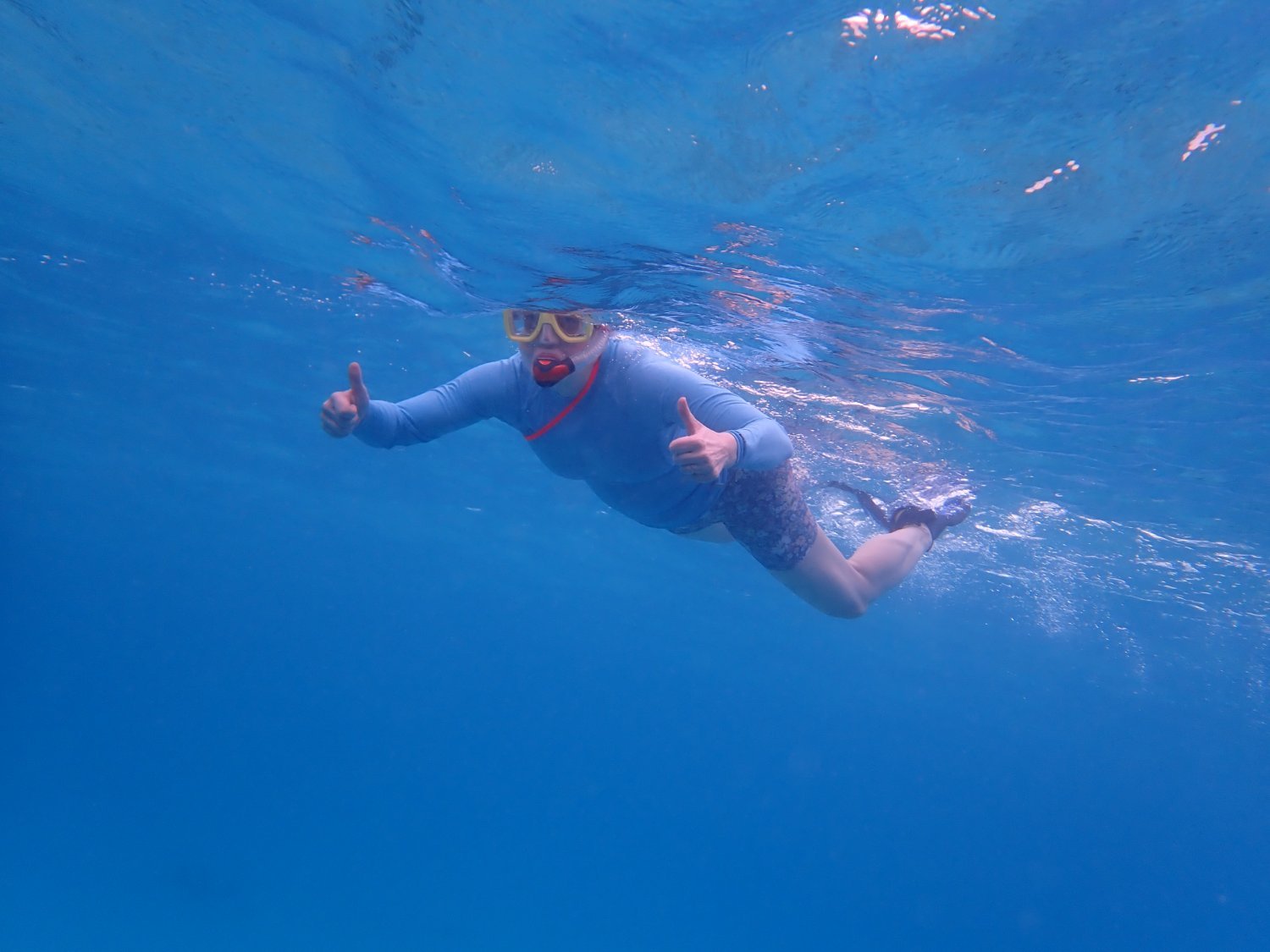
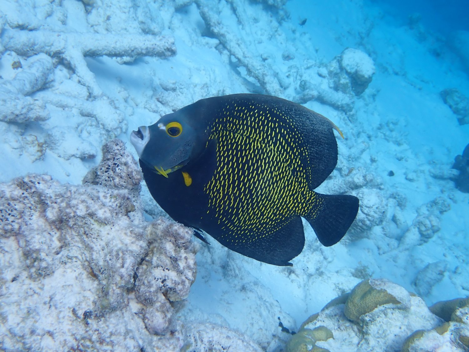
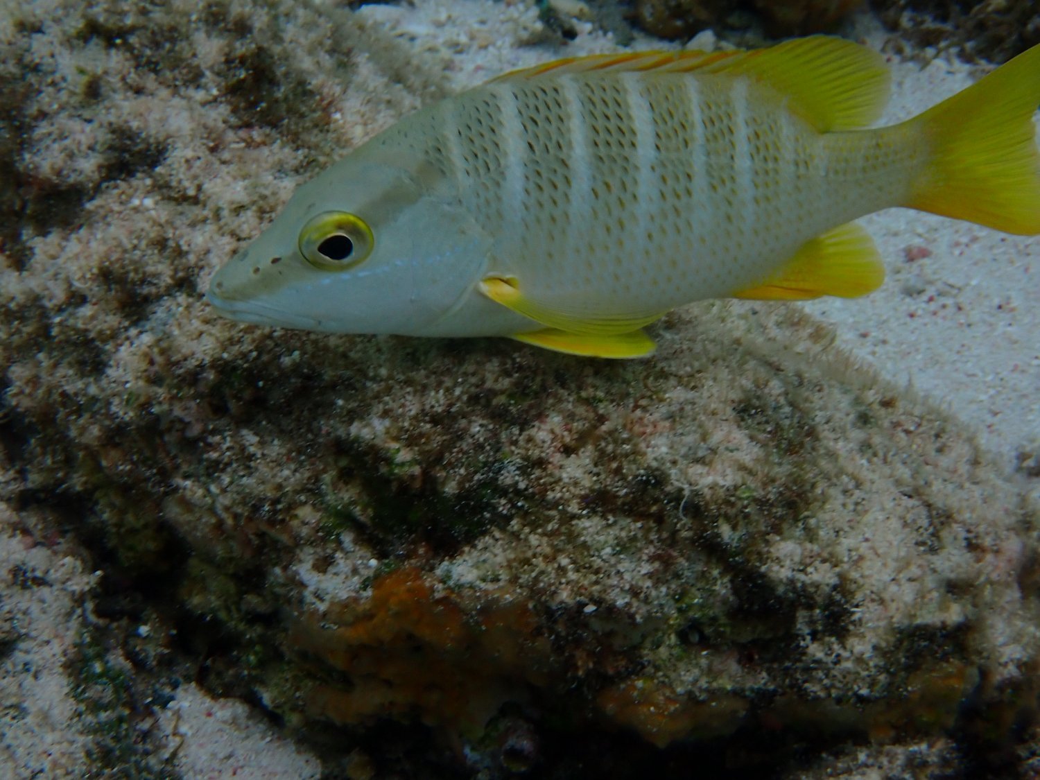
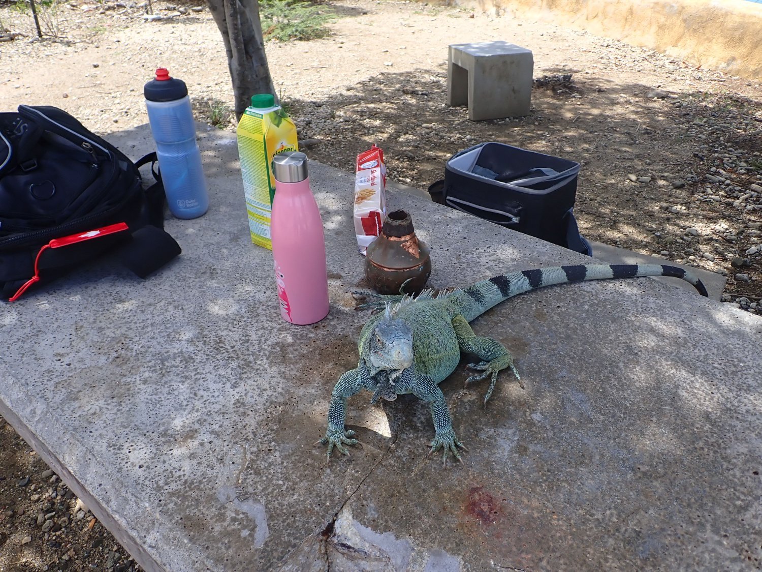
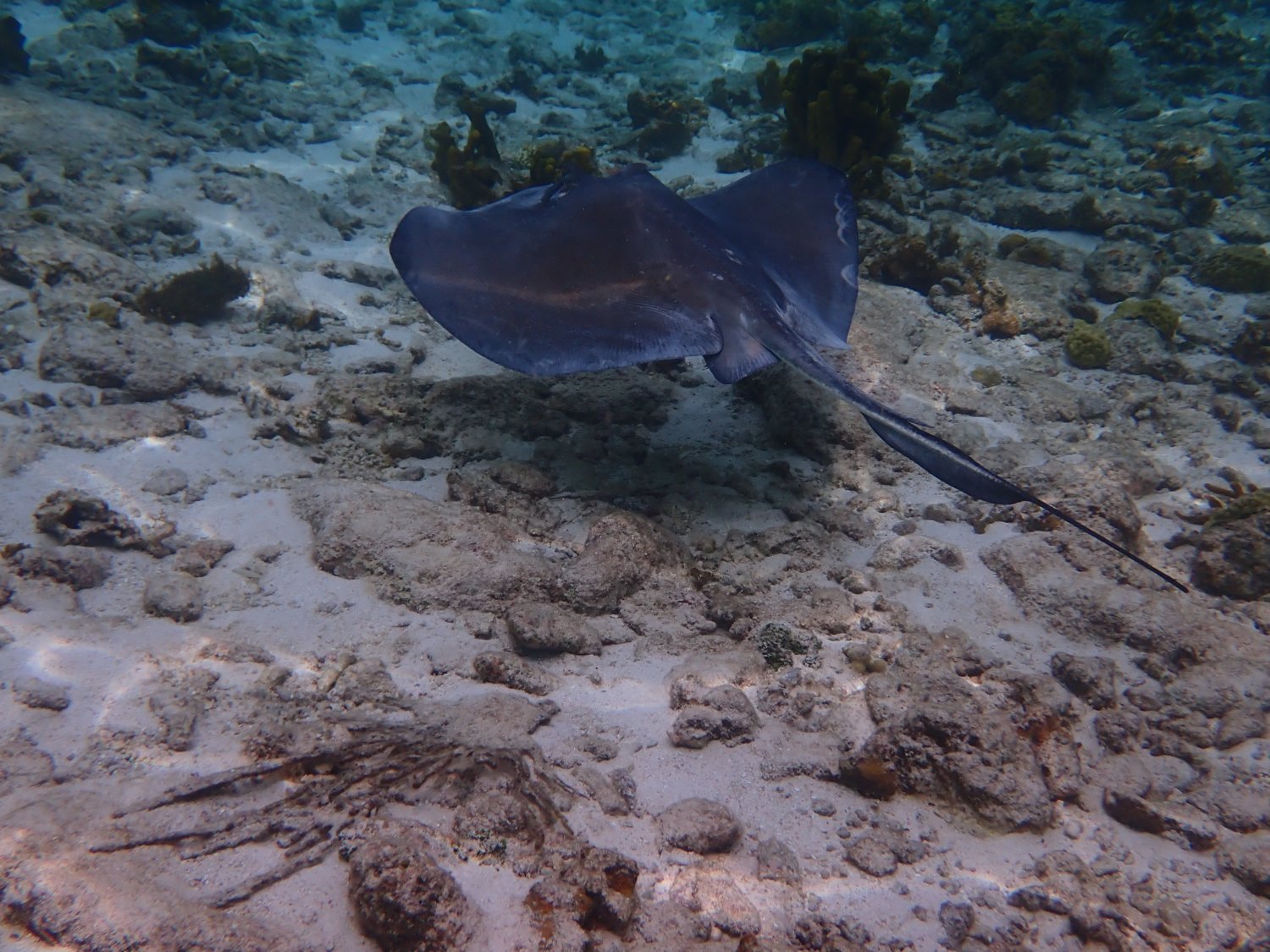
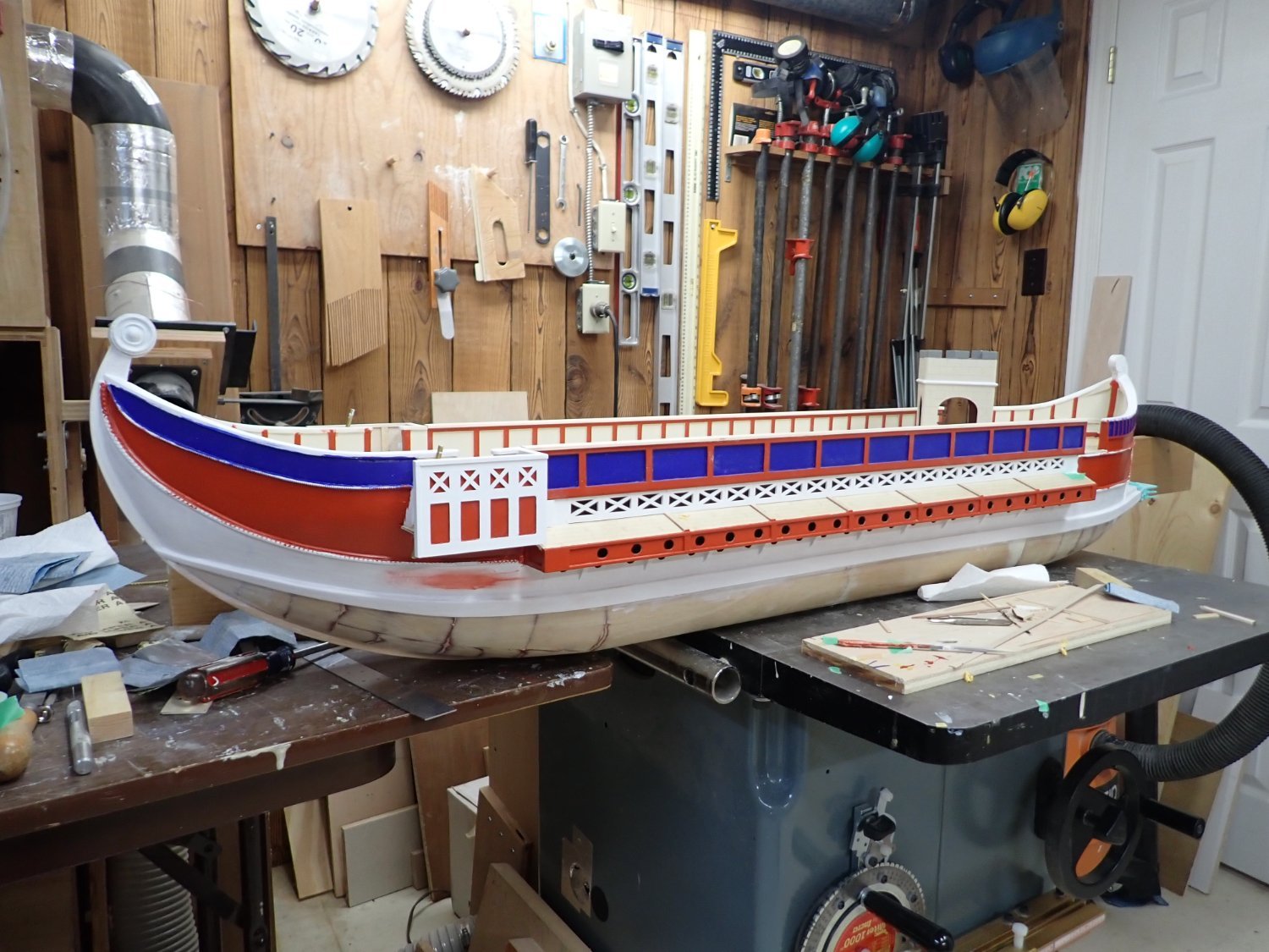
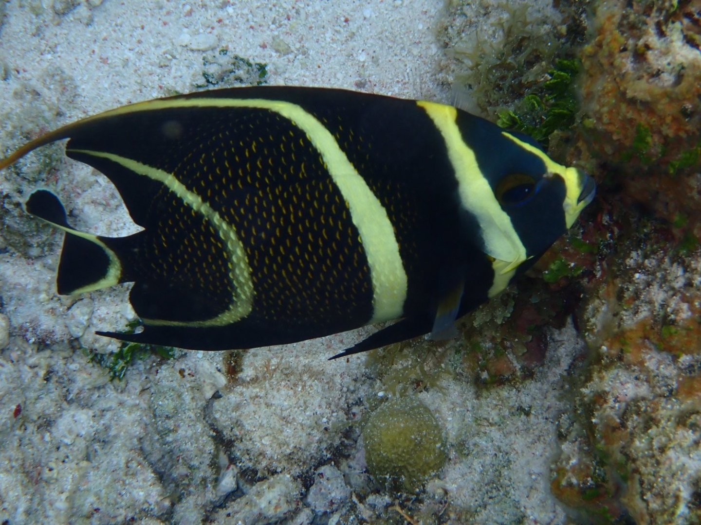
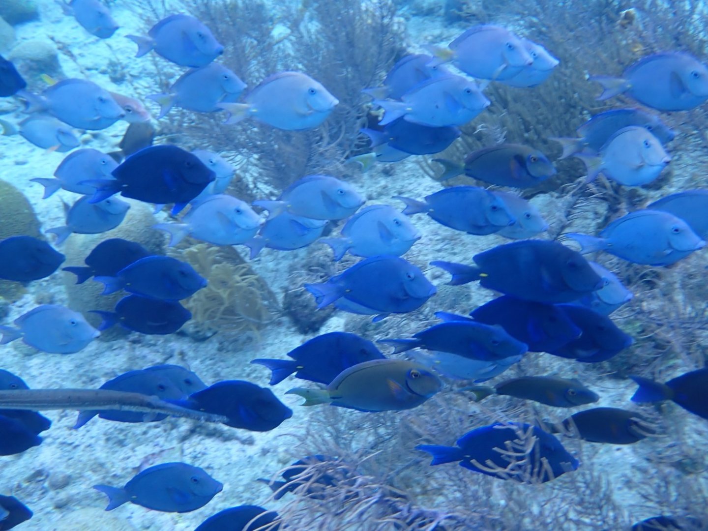
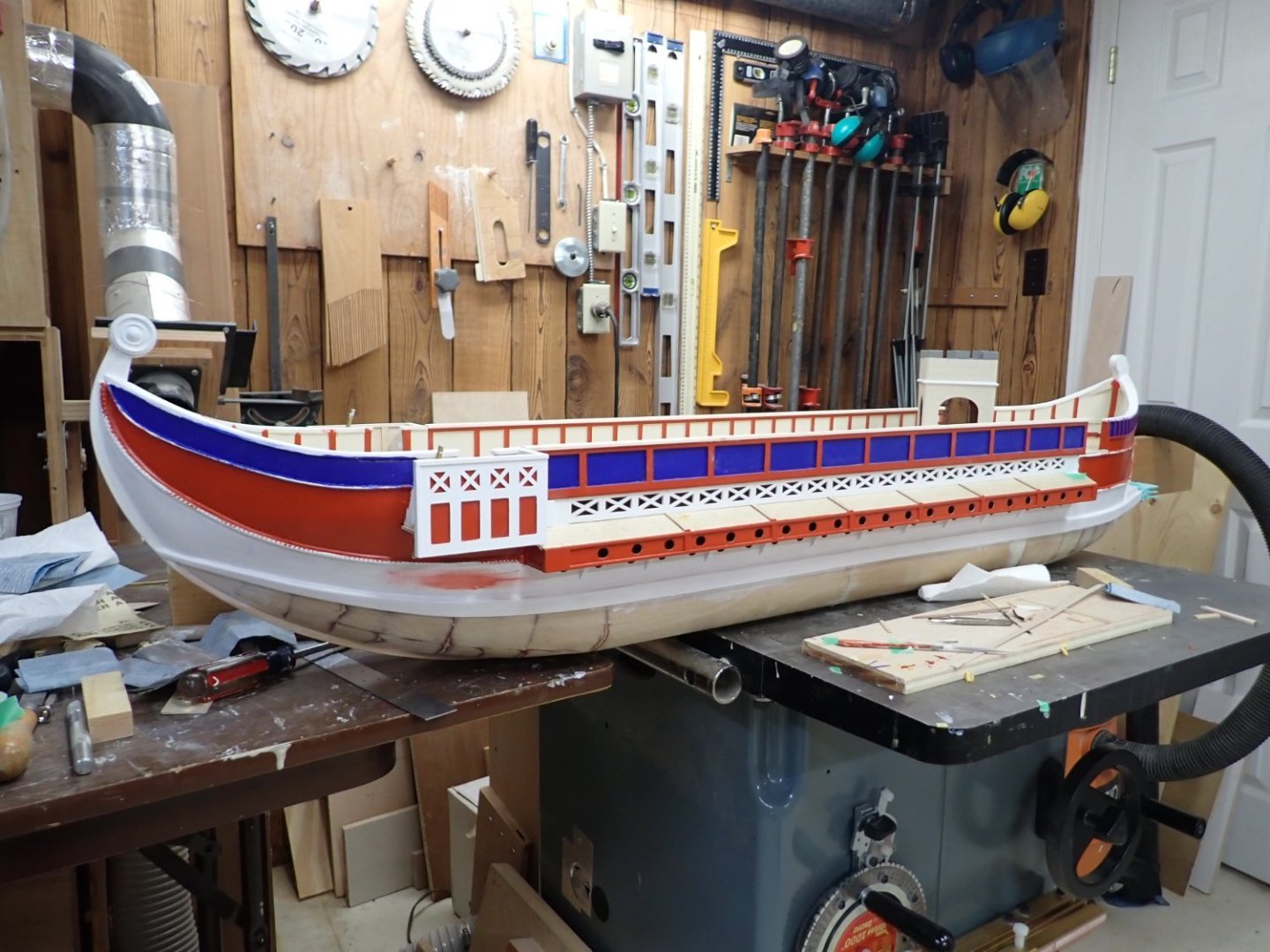
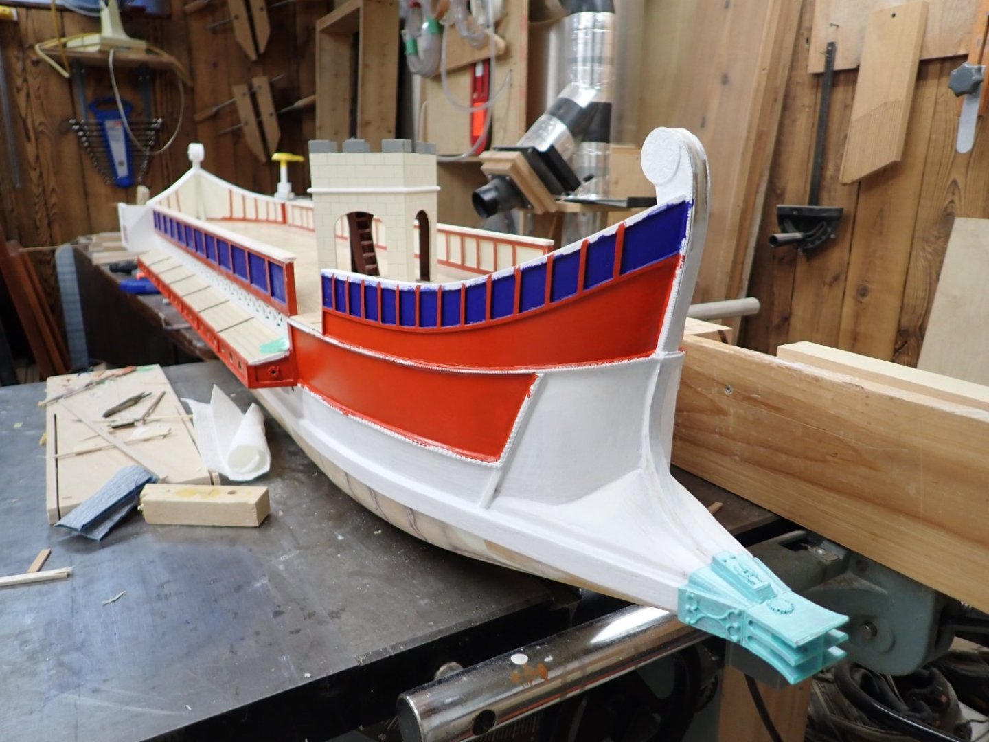
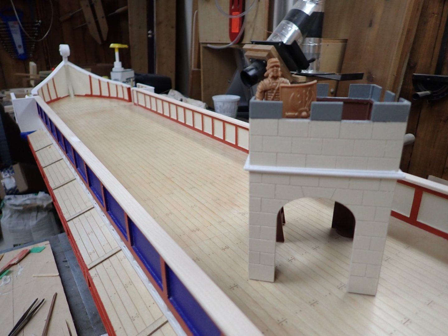
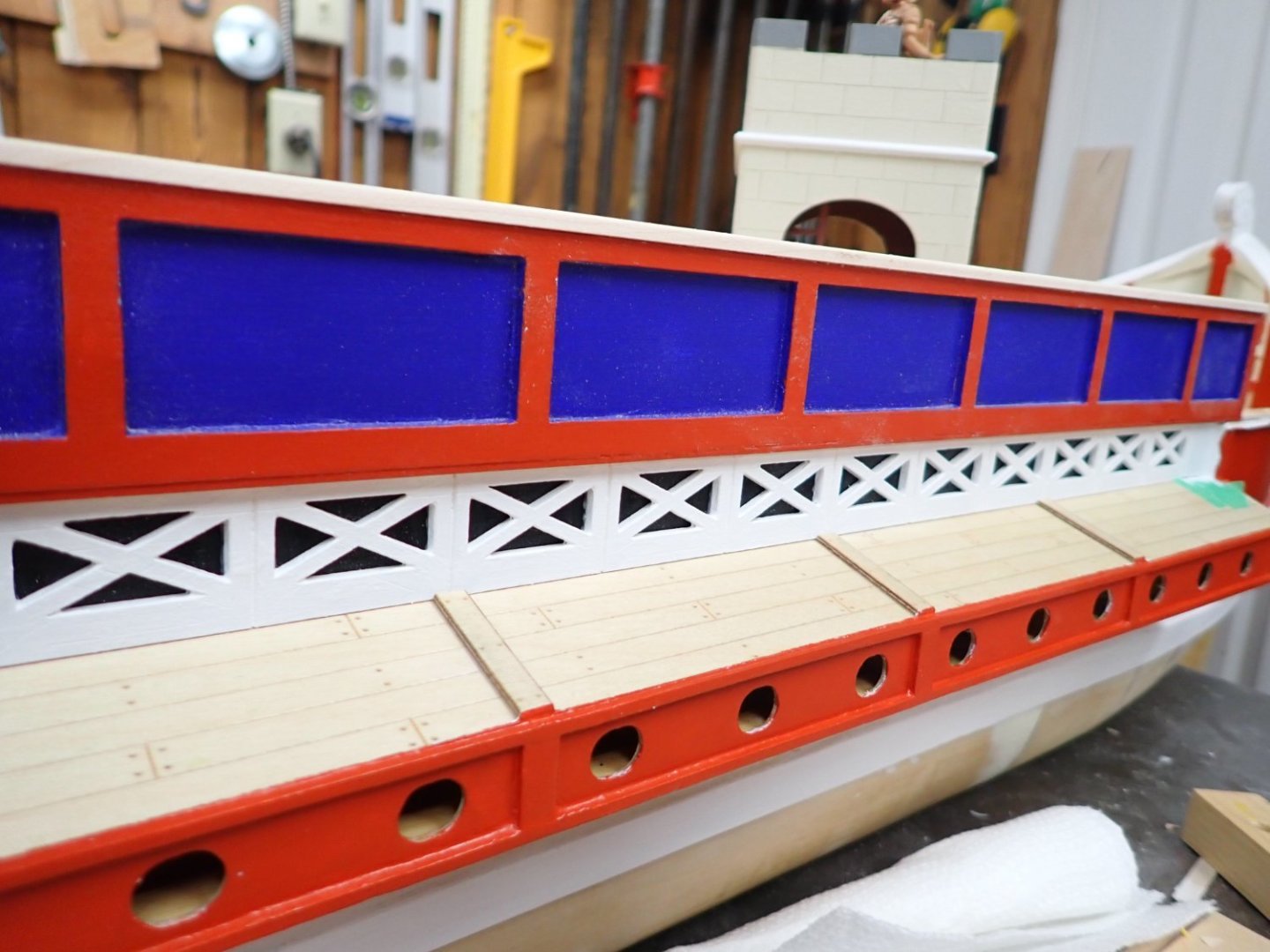
Great trip but back to reality. Bonaire is for scuba/snorkeling on its 1st class reef; there isn't a lot else to do there. There may be a night club in Kralendijk but we're too old and tired for that stuff. Lots of tasty seafood dinners. I'm very pleased with my underwater camera (Olympus TG-6) except that it doesn't have much zoom power. For example here are a few shots I took: Anyway, back to our regular programming. Wednesday afternoon I will be rowing the galley in a local pool which will be its debut to the RC boat club members. I've been slowly painting it but must stop now to let the paint cure. I haven't painted anything that will be in the water; after Wednesday I have another month to finish painting and to clearcoat it for protection before the last winter indoor pool session. I will spend tomorrow improving the oar mechanisms (according to findings of the September trial in our pool) then reinstalling to make all ready. Below the red and above the main wale will be "natural", the same colour as the inner bulwark panels to represent unpainted wood. Below w/l will be not-quite-black including the quadrilaterals at the bow. The black will extend up the stem and stern posts and also be on the cap rails. The decorative bits between the colours will be yellow. Some stem decorations will be gold. I still need to add the shield motifs in the outer bulwark panels. Still need to make rudders, scorpion artillery, fantail decorations, deck ventilation hatches, two fake access ladders to belowdecks, mast and yard, artemon and yard, aft flagstaff with eagle atop, and of course a crew. Oh and I still need to shorten the upper oars by 1/2" as discussed previously. Will try to make a video at the pool. Planning to take my bathing suit, just in case. 😐


- 536 replies
-
- 13
-
-
-
- Quadrireme
- radio
- (and 1 more)
-
Too-cool summer down there, too-warm winter up here. Outdoor skating and skiing haven't been memorable.