Ian_Grant
-
Posts
2,156 -
Joined
-
Last visited
Content Type
Profiles
Forums
Gallery
Events
Everything posted by Ian_Grant
-
 The makerspace was opened in collaboration with the US embassy; someone enterprising must have known someone there.
- 536 replies
-
- 3
-

-
- Quadrireme
- radio
- (and 1 more)
-
Thought I should expand on this. Their closet has sheet MDF, plywood, paper card, and lexan, all at very low prices. If you bring your own material, there is no charge for using either of the laser cutters. As I said there is a very low charge for plastic filament you consume in the 3D printers but no additional charges. The three printers are Makerbot Replicator+ marketed for educational institutions. They are really no muss, no fuss. There's no fiddling trying to get the base perfectly level; when your print is done you unplug the plastic baseplate (they are covered in masking tape to prevent the hot print from melting to them) and flex them to release your print. I've never seen them have a problem during printing. Ten year old kids are there using them sometimes, downloading dragons or whatever from Thingiverse. Lots of fun!
- 536 replies
-
- 4
-
-
- Quadrireme
- radio
- (and 1 more)
-
Geez Marc, you keep raising issues that I will have to deal with when I get to my stashed SR. 😬 You made an excellent job of it. Not sure if I could keep them round and evenly tapered working manually. Will see if/when I get there. Keep up the beautiful work. Merry Christmas!
- 2,699 replies
-
- 5
-
-

-
- heller
- soleil royal
- (and 9 more)
-
Bill, I know what you mean. I was hugely impressed when I went to a place that uses a blast of water to cut metal or whatever. I just wanted him to cut some porcelain tiles neatly for my fireplace but when I walked in it was slicing through 1" aluminum like it was butter.
-
Yes it's quite a deal; they're not out to make money on it even though there are tens of thousands of dollars worth of machines to maintain. They also can supply MDF sheets out of their closet in various thicknesses at ridiculously low prices, wholesale I suppose. Good question about the steering platform shape....the books I have show them square but possibly no one really knows for certain.
- 536 replies
-
- 2
-
-
- Quadrireme
- radio
- (and 1 more)
-
They just charge for the plastic you use, by weight according to what the maker software calculates will be needed. For example, the ram cost me $1.60, speaking of which I printed it again with some changes and also in four pieces so the decorative elements came out perfectly.
- 536 replies
-
- 3
-

-
-
- Quadrireme
- radio
- (and 1 more)
-
Thank you Michael! Yes it has encompassed a broad range of challenges, starting with me writing software. 😏 Looking forward to painting the crew. Thanks Pat! Not too much longer to wait, I hope.
- 536 replies
-
- 2
-
-
- Quadrireme
- radio
- (and 1 more)
-
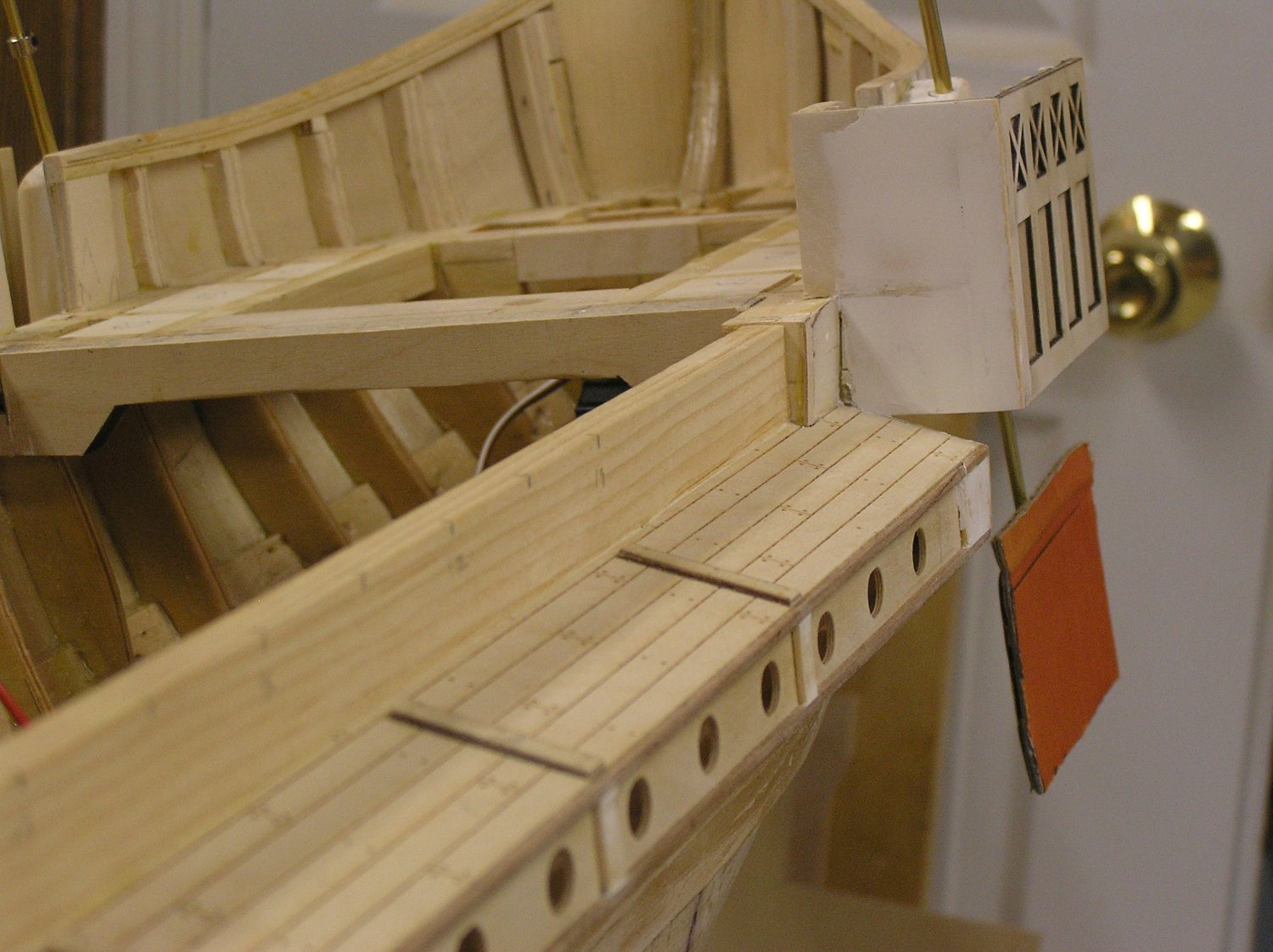
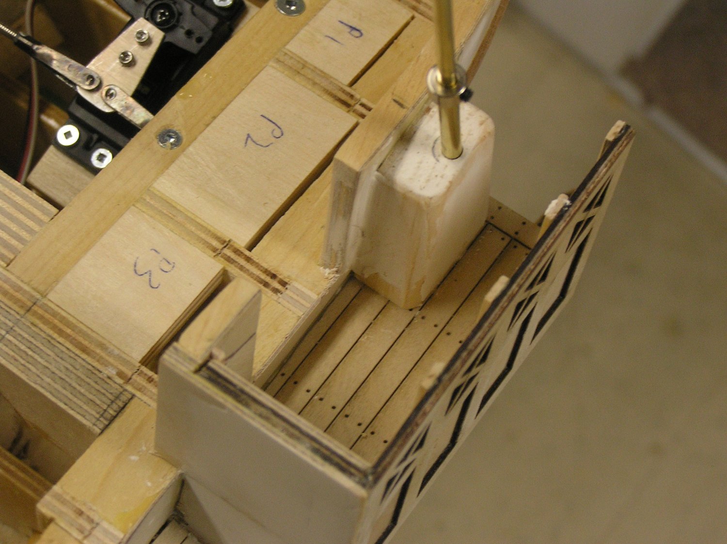
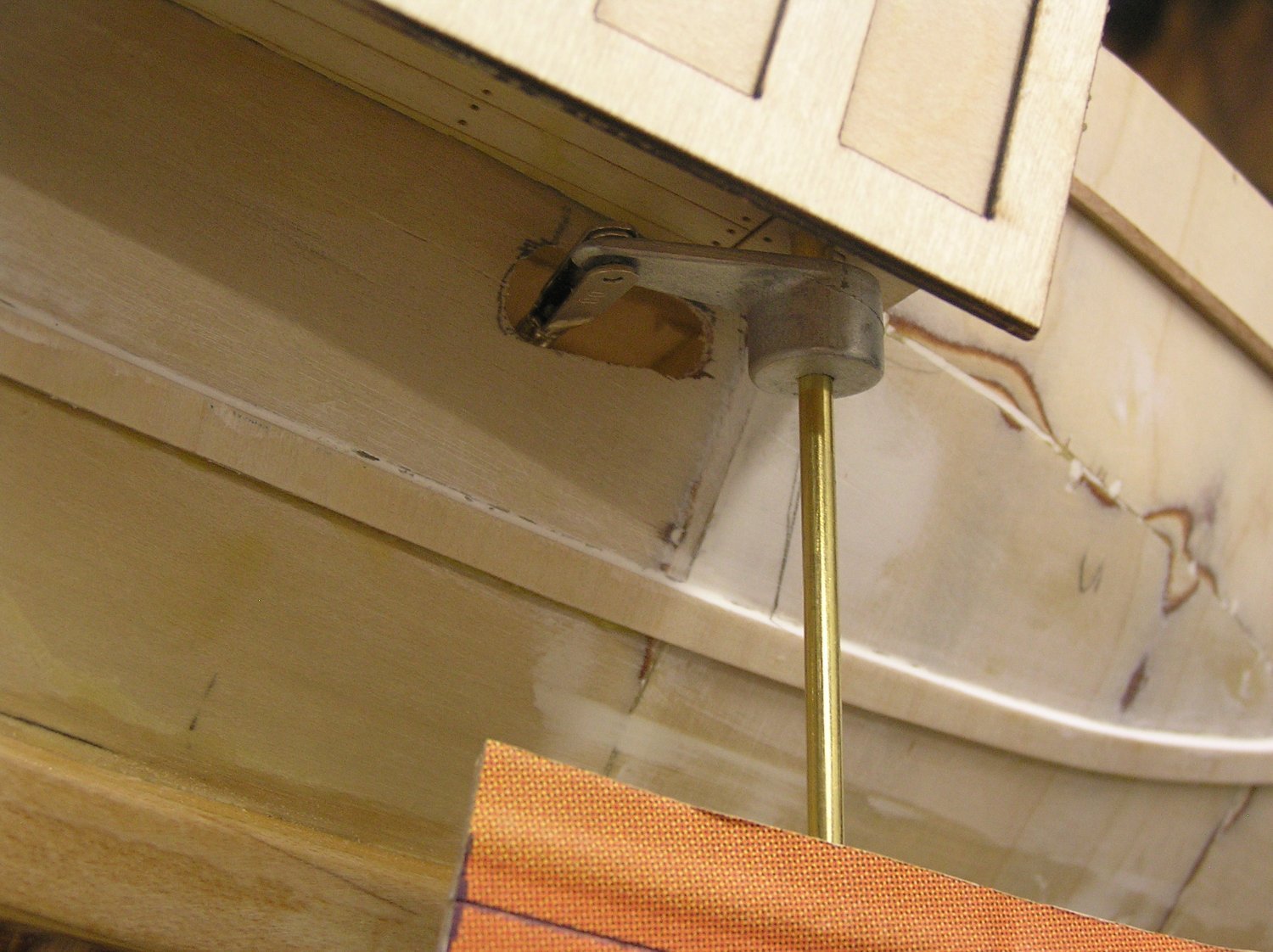
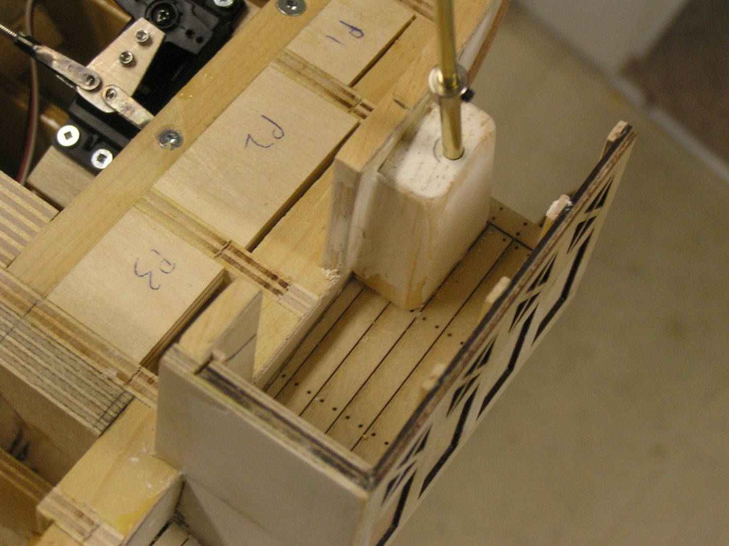
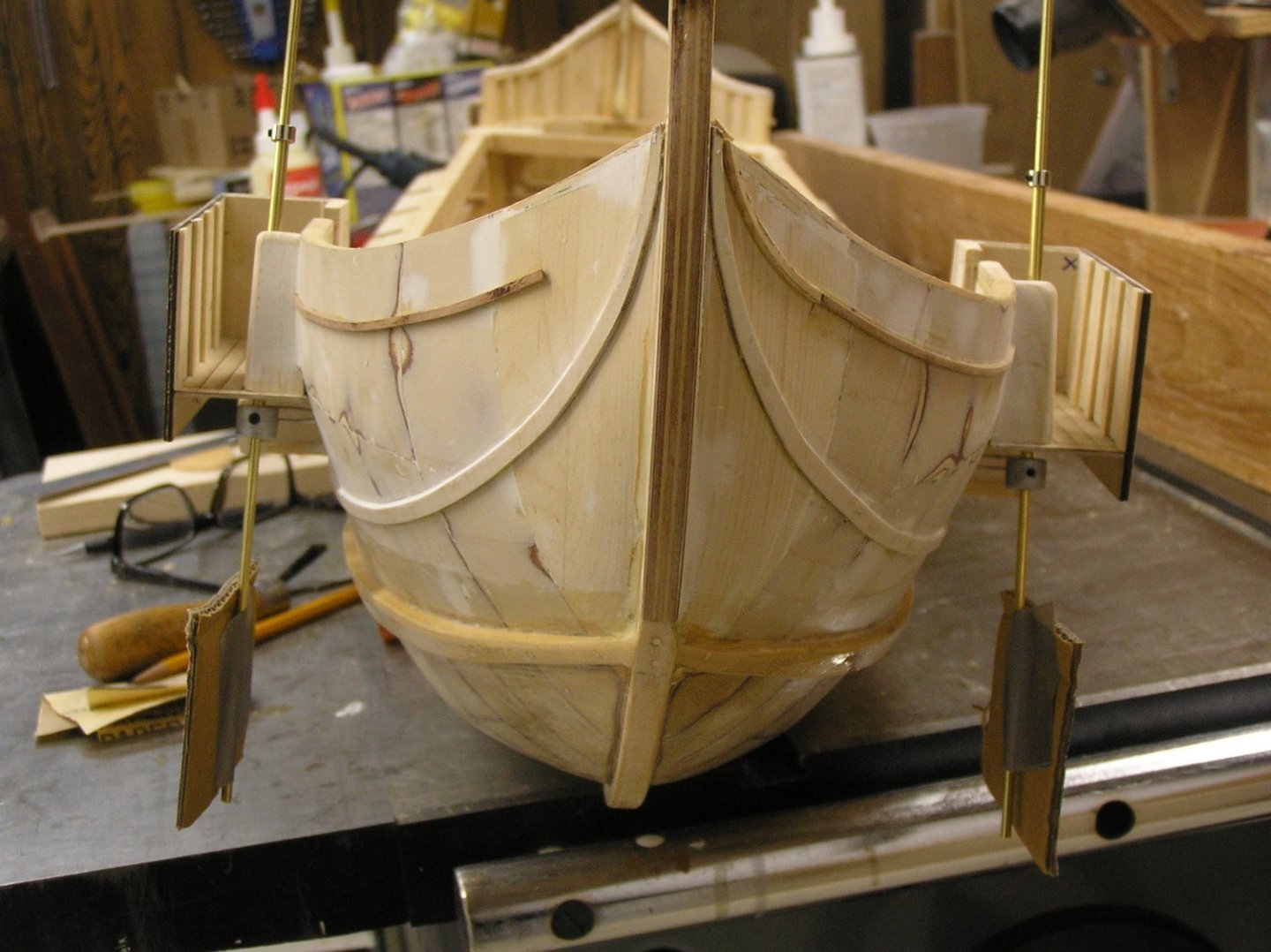
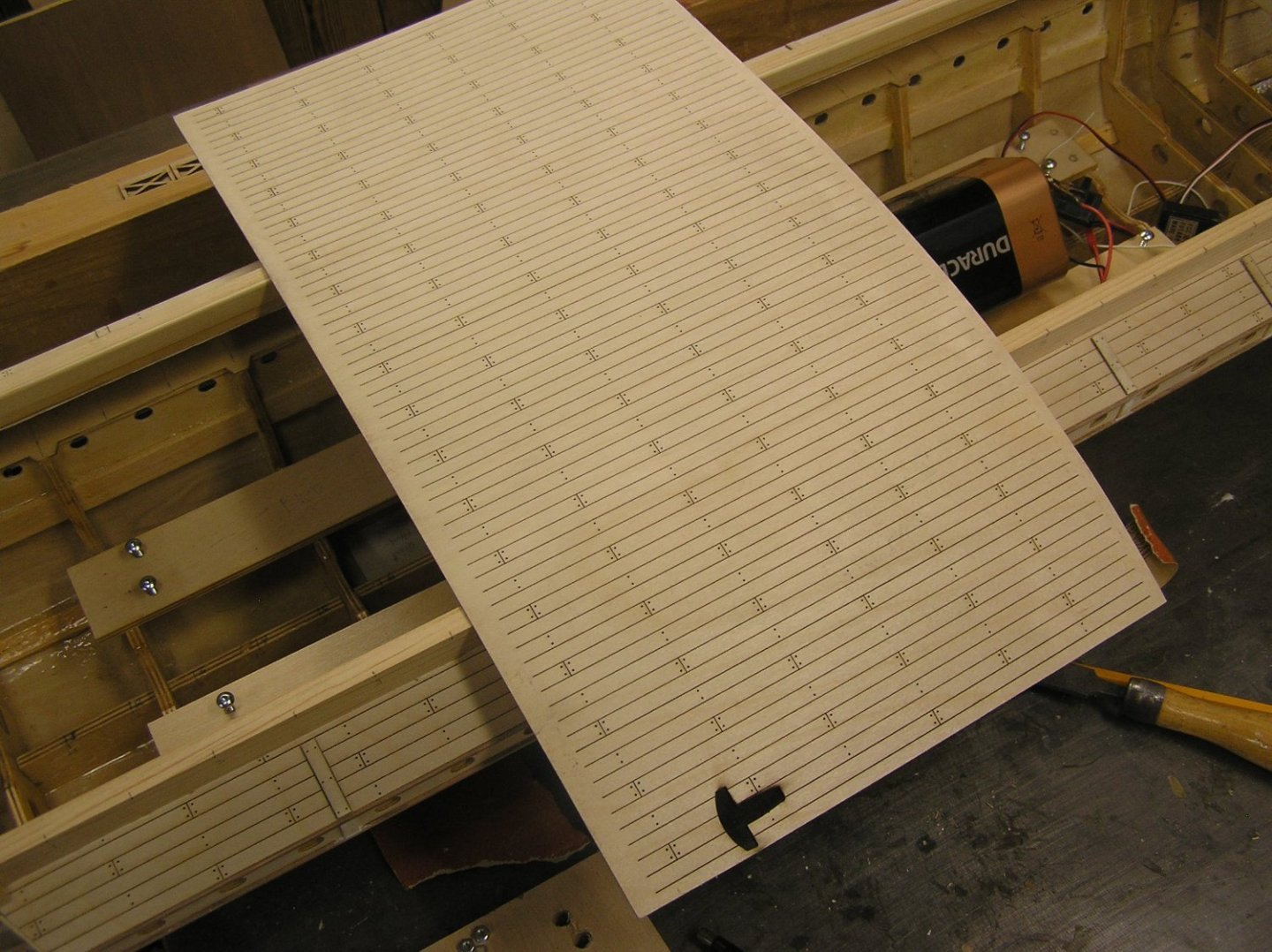
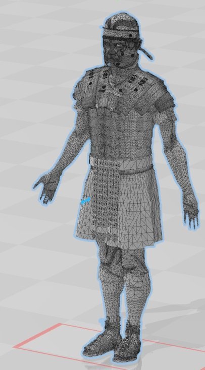
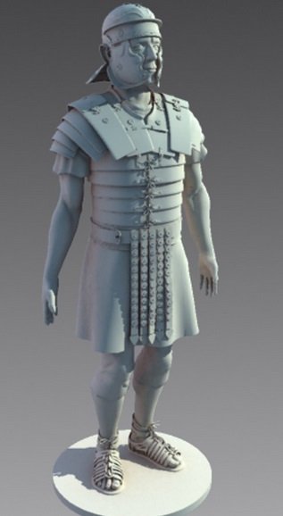
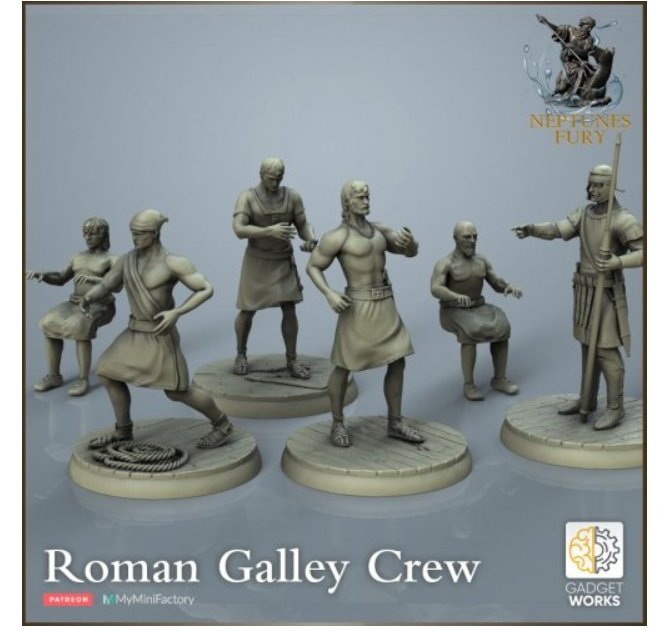
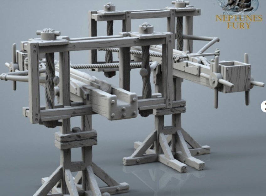
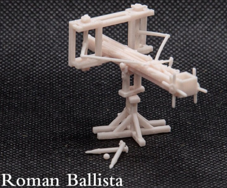
Quite a bit to talk about. I came to like the width of my steering platforms less and less; they stuck out like cauliflower ears whereas they should be about the same as the outrigger. Thinking about rudder installation, I realized I could make the steering platforms narrower if I let the rudder horns swivel through the hull skin when swivelling inwards (I had sized the platforms to let the horns traverse their full arc beneath them). Just means enlarging the slots in the hull through which the rudder linkages pass. So, I cut the platforms off the hull, reduced their width by 3/8", and re-mounted them. I formed two wood blocks shaped to fit against the hull at the back of the platforms, and drilled through them at an 18 degree angle for the brass rudder tubes. Formerly the steering platform front walls had two panels similar to the side walls, but the inner set was destroyed when I hacked off the 3/8" and rather than make new walls I just covered it with another layer of 1/16" ply yielding a blank wall as seen below. I'm now planning to put a relief lion's face on each of these walls. There are lots of free 3D lion face files available on the web. The new, narrower steering platform. The formed block holding the rudder tube 1/8" ID, angled at 18 degrees from vertical. Brass rudder tube and rudder shaft are yet to be trimmed to length. You can see the upper collar; the horns act as the lower collars. Horn beneath the platform; 1/8" DIA brass rod rudder shaft; linkage disappearing into the hull. I'm thinking of making 3D printed flanges to clean up the linkage holes. Here's a little video of the cardboard pretend rudders moving. They are 2" x 3" which pool testing showed would turn the hull. I'm planning to make the actual rudders by, altogether now, 3D-printing using transparent filament. I can then paint on scale rudder blades and the extra will be invisible when rowing near shore. Of course, the real rudders will include a tapering wide blade all the way up to the steering platforms, hiding the brass rod. Rudder servo is offset to one side to ease insertion of the NiMH battery pack through the aft access hatch. PB290334.MOV I will soon be adding the fore and aft portions of the deck. To that end, I laser etched deck planks on a wide piece of 1/16" ply as seen below. This will be split in half to do both ends. Note the hole: That was my mistake as I started the laser but still had a previous file loaded (OOPSIE). Fortunately two corners will be trimmed off to form each of the two decks. Now, more on 3D. I bought a 3D OBJ file for a Roman legionnaire who is "fully rigged", meaning one can pose him as desired before printing. I am allowed to make as many men as I like since I paid for the file (Cyber Monday Sale!!). I can scale him as I like; I could even make crew of varying heights. Here is a picture of what the model looks like. One can pose him right down to how the fingers are bent, apparently. Maybe even facial expressions (what can be seen behind his face protection). Here he is imported to 3D Builder. I'll need to import him into Blender to use the posing functions; I just wanted to see him. My brother emailed me about 3d "Roman Sailors" he found, which I also bought on Cyber Monday. Here is what they look like; not readily poseable (brother says he can do it manually, but ouch!), and I have no use for the rowers, but they only cost me four bucks and again I can print as many as I like, even if only to cut up to pose. What's more exciting for me is that while on the site, I noticed they also had ballista files!! I had made a start at drawing these in TinkerCAD but due to my lack of CAD skill I was forced to draw the later period metal type which is simpler. Have a look at what they offer; the older wood type with twisted sinew torsion springs and all! Resin printed, these should look amazing on deck. Picture of CAD ballistas; Picture of a resin-printed ballista; I will need to scale it to suit. Painting should bring out the details. Speaking of painting, I'll need to acquire some figure-painting skills to do my crew justice. Need to learn about washes especially. I installed the upper trim pieces at the stern (port side incomplete). I couldn't edge bend the wood right at the sternpost (I'm not into steaming) so I cut the last section from a small sheet. Not perfect but this trim will be covered by some previously-shown Etsy bling. Hopefully I will have the rudders at the next update. Snag is that the library is nearly out of transparent filament and I don't know if what they have is enough for me. They won't order new until they run out apparently. Till next time! Thanks for following, and Happy Modelling!


- 536 replies
-
- 14
-
-
-
- Quadrireme
- radio
- (and 1 more)
-
Glen, you'll be speaking Hawaiian and downing mai tai's by the end of this build. I love a good mai tai.
- 174 replies
-
- 5
-
-

-
- Waa Kaulua
- bottle
- (and 1 more)
-
We were there last year. The chickens hang around outdoor eating places, like the food wagon circles, hopping up on tables sometimes before people have even left. They are strolling along everywhere. They didn't bother me, in fact a hen with her chicks following is pretty cute, and some of them are beautifully coloured. But the roosters cock-a-doodling at 4:30am got old, especially one fellow living beside one of our rented places who started at 3:30am each morning.
- 174 replies
-
- 6
-
-
-
- Waa Kaulua
- bottle
- (and 1 more)
-
Hi Michael; I see you cut the quarterdeck off of the maindeck. Why is that please?
- 327 replies
-
- 1
-
-
- Sovereign of the Seas
- Airfix
- (and 1 more)
-
Well on the way to another heirloom work of art.👍🤙Hang loose!
- 174 replies
-
- 5
-
-
-
- Waa Kaulua
- bottle
- (and 1 more)
-
Michael, I bought this same kit at a church garage sale. Nothing had been done to it. All the parts seem to be present, but many of the tiny masts/spars are warped or broken, enough that I would need to make wood replacements. I pondered how to tie off real shrouds at the deadeyes, among other things. In the end I shelved it for now. I will be keenly interested to see what you do with this kit in creating your next masterpiece, to guide me in a possible future build. If my eyes hold up. ☺️
- 327 replies
-
- 4
-
-
- Sovereign of the Seas
- Airfix
- (and 1 more)
-
She goes well in water! Vital for a lifeboat ..... Congrats!
- 56 replies
-
- 1
-
-
- Colin Archer
- Radio
- (and 1 more)
-
Totally missed this build until now. Very cool!! Well done!!
- 51 replies
-
- 4
-
-
- Sea Installer
- Bottle
- (and 1 more)
-
What an awful lot of work over the fiberglass disaster! 😬 Nowadays you could use West System epoxy resin which comes with pumps to ensure the correct ratio. And less smell ....
-
Definitely a Hellerism. Those are the main topgallant braces, led back to the highest practicable point on the mizzen mast. My old instructions have the same error in DIA "Les Voiles Sur Le Mat d'Artimon". Yet those same instructions, on the cover sheet, have the large side view that clearly shows these lines meeting the mizzen topmast just below and just above the crosstrees, above and clear of the sail as you suspected they must be. What I would do is tie them off on the topmast itself above its shrouds (or maybe to the forward crosstree each side??), pass them up and through the main topgallant brace blocks on their pendants, then down through a couple of blocks attached to the rear crosstree each side of the mizzen topmast, and down to wherever on deck. Just my opinion. Interestingly, French for mizzenmast would appear to be "artimon", which is the same word given in my books for the forward-projecting spar at the bow of a Roman galley which can be likened to a bowsprit, sort of.
-
As you know Bill we in Canada had our Thanksgiving some time ago; hope you enjoy yours!!
- 1,508 replies
-
- 1
-
-
- Le Soleil Royal
- Heller
- (and 1 more)
-
Glen, as a precaution please be sure to check out these tropical woods for potential toxicity when sanding! Safety first ..... 🐘 <- (Elmer the safety elephant, who my kids never heard of from school). ps I know a guy who built cabinets from some unusual wood or other, and rubbed sawdust all over his forearms to prevent him sweating on his sanded surfaces. His whole body broke out in hives for several days and he swore he'll never touch that wood species again.
- 174 replies
-
- 6
-
-
-

-
- Waa Kaulua
- bottle
- (and 1 more)
-
Glen, glad you're back with another unique project. Looking forward to seeing it evolve. And at 1/100 scale this could be your first bottle ship where you could have an actual crew!
- 174 replies
-
- 4
-
-
-
- Waa Kaulua
- bottle
- (and 1 more)
-
She does look even better.......