DONATION DRIVE - SUPPORT MSW - DO YOUR PART TO KEEP THIS GREAT FORUM GOING!
×


Ian_Grant
-
Posts
2,141 -
Joined
-
Last visited
Content Type
Profiles
Forums
Gallery
Events
Everything posted by Ian_Grant
-
 Bill, yes I built the Revell CS and Connie many years ago. I think I still have the instructions. No, I don't recognize the blocks tied to the gammoning (which incidentally is drawn incorrectly wound). Can't see which lines they want to tie to these blocks but I would guess they are the ones that ought to go to the knighthead blocks.
 -
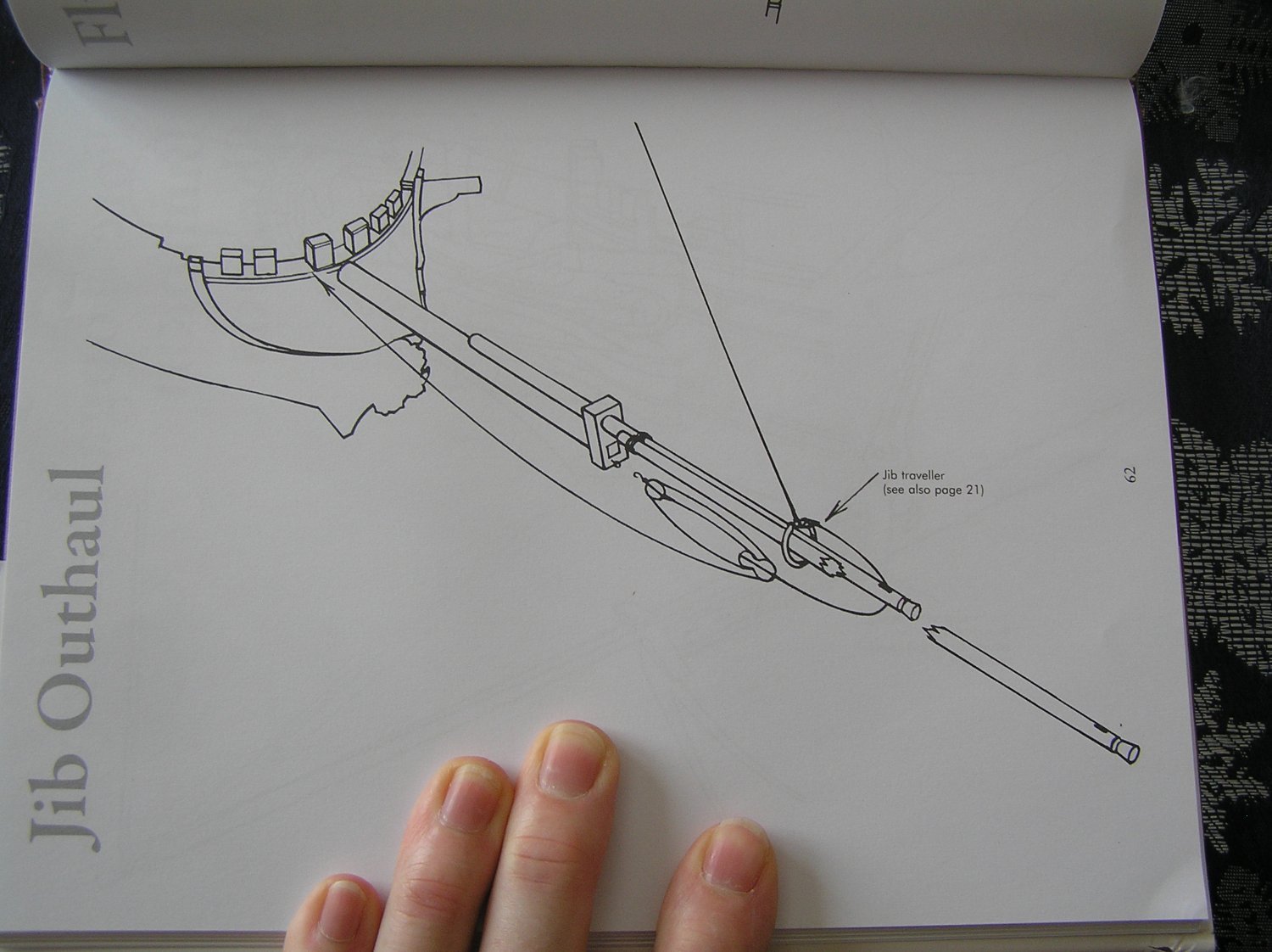
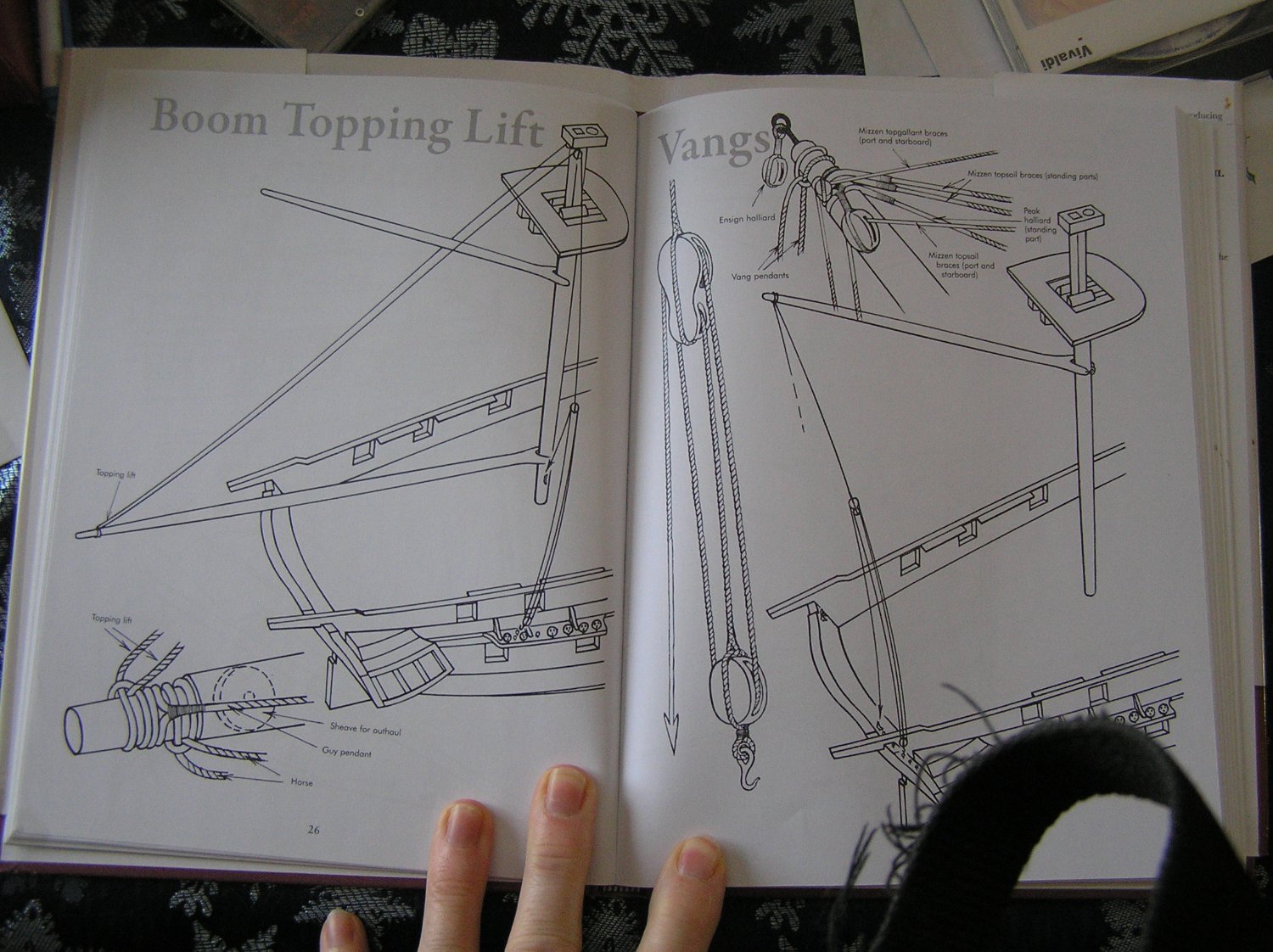
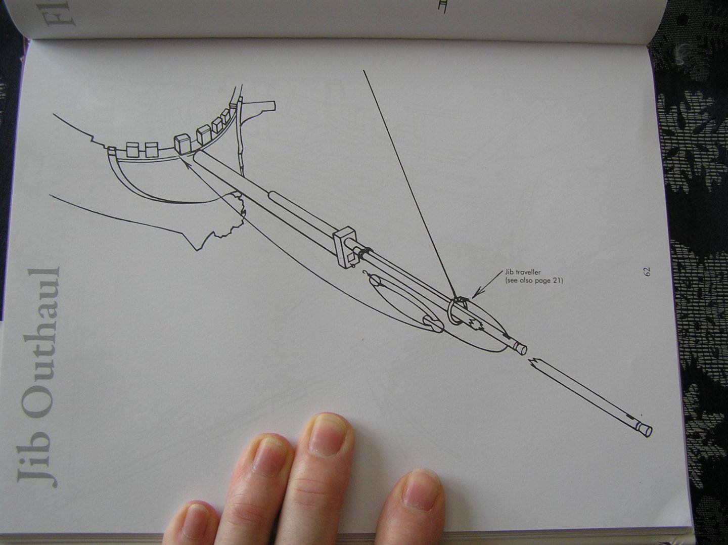
Bill, one shortcoming of my Longridge's book is that many rigging lines are depicted only partly in diagrams, and there are critical bits of related info in text, often many pages away. It makes for a lot of page flipping back and forth. As you say, the information is right there in front of you, but difficult to connect sometimes. Are you aware of "Rigging Period Ship Models" by Lennarth Petersson? I bought it partway through my Victory build. This very useful book depicts each line in a beautifully clear single diagram. Just look the name up in the index, flip to the page, and behold - crystal clarity. There is no text at all in this book other than a foreword and page titles. If you want to familiarize yourself with the rigging this is a great book. However, it does not go into the actual purpose of any given piece of rigging, although the purpose can often be inferred when viewing the diagrams. Further reading may be necessary .....ie yet other books. Note that Petersson made these detailed sketches from contemporary models of a particular ship, namely the frigate "Melampus", so the details such as the belaying pin location need to be adjusted. Also, first rates like Victory differed in other details compared to a frigate. However, Petersson can be used to get the idea, then consult my Longridge's book for further nitty-gritty. Here are a couple of examples from Petersson, a propos of what we have just been talking about. And another just for luck:

-
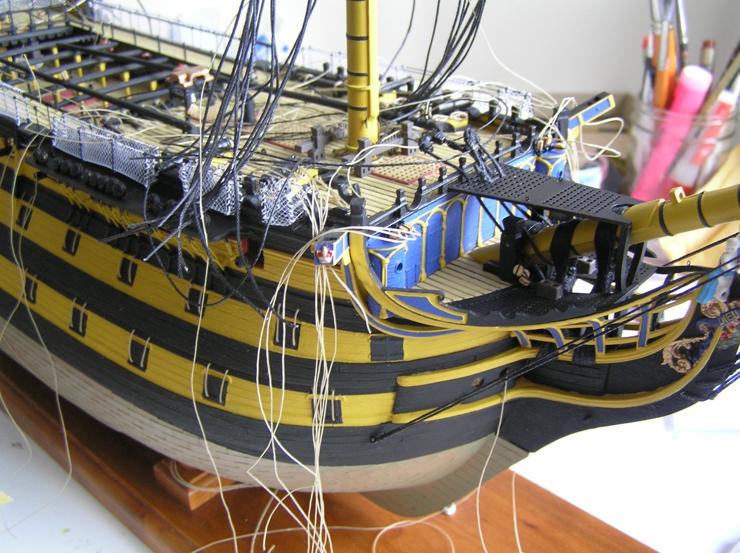
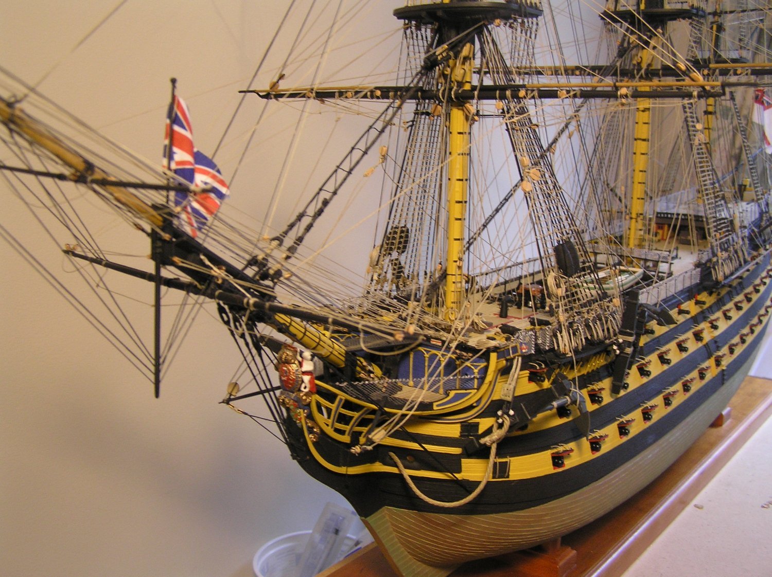
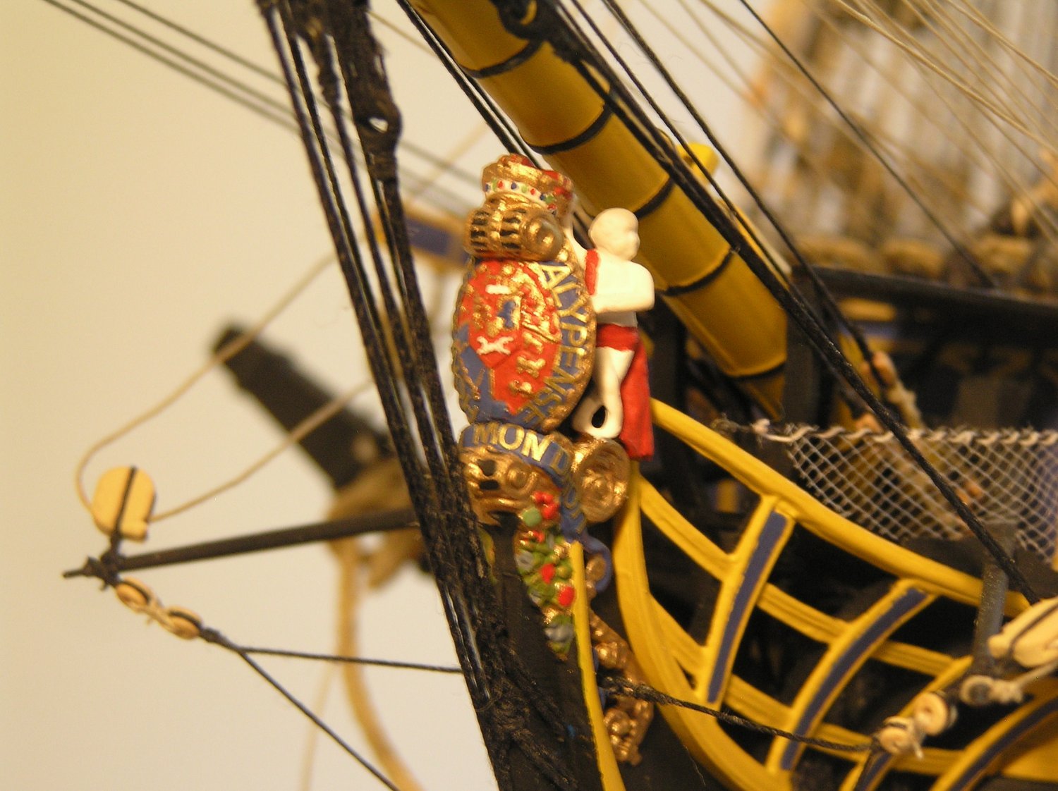
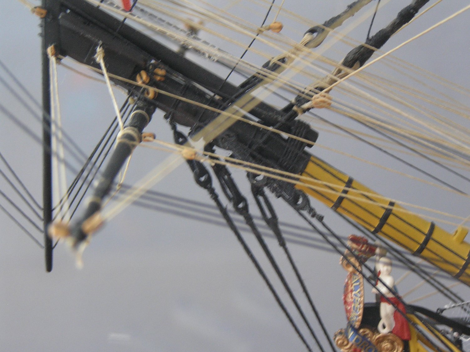
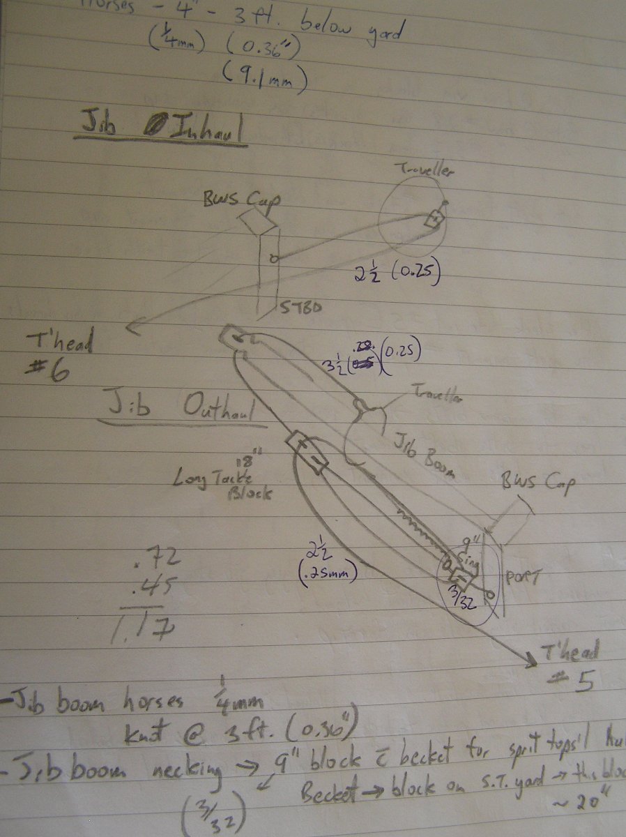
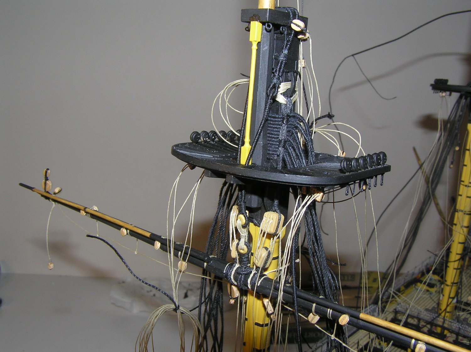
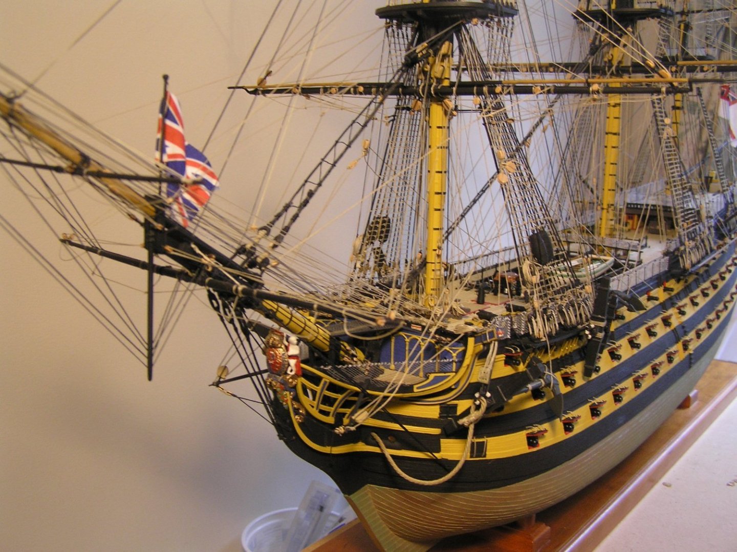
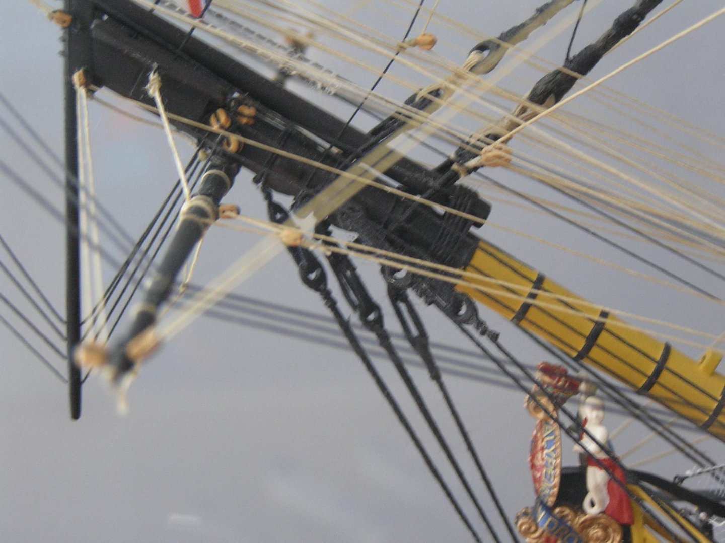
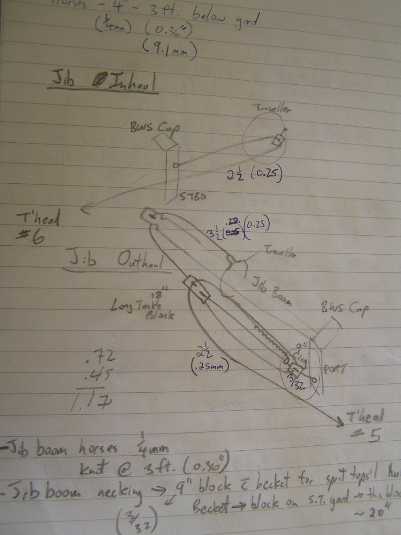
Bill, re your query about pics of bowsprit rigging: apparently I didn't take many shots of this area but here are a couple I found which may be of use. This one shows an early stage. You can see the three threads from the single blocks attached to eyebolts over each roundhouse, ready to rig into tackles for the guys (see pg 266) which each end in a double block (see bottom pg 227 / top pg 228). Also seen are the collars for the main stay and preventer, which you should think about now as access rapidly diminishes in this area. You can also just make out the blocks attached to the front of the knighthead. This pic shows the boomkin guys rigged with thimbles. Also the block for the fore tack to which I added a small piece of wood to create the shoulder. This shot shows how very busy the forecastle rail gets with multiple ropes belayed on each timberhead. Of note is that the forecastle hands were the oldest and most experienced in the ship since they had to handle both the foremast and the headsails etc. At the extreme left you can just make out the jib traveller, with the jibstay and inner martingale attached to it. Sadly the traveller inhaul and outhaul cannot be made out. I took a couple of new shots through the case (then the camera battery died 😭). This shot shows the blocks crowded above the spritsail yard through which the martingales and fore royal stay pass (see pg 227 "Martingales"). These then connect via tackles to some of the blocks on the knightheads (see notes at top of pg 266). This shot shows the guys rigged with the aforementioned blocks over the roundhouse. You can also make out the tackles at the knighthead. Note the multiple ropes per timberhead, it must have been a bear to operate. Lastly, Longridge lacks a clear diagram of the inhaul and outhaul arrangements for the travellers. Here is a shot from my notes, where I was trying to make sense of it. It's pretty sloppy so I will summarize: The inhaul is straightforward; from an eyebolt on the bowsprit cap, through a block on the traveller (see Fig 164 pg 235) and back to a timberhead. The outhaul runs from the shackle on the traveller, through the sheave hole at the outer end of the jib boom, and back to a long tackle block which I made by gluing two blocks together. The pendant for the outhaul starts on the ar*e (Edit: I had the full word typed in but when submitted it changed to ****, LOL) of a single block on the port side of the cap, runs through the long tackle block, back through the single, again through the long block, then to a timberhead. That should help you out................


-
Oh damn, we were in Oxford too but didn't know about pitt's River. I'm still kicking myself because we also went to Bath and I didn't know the "Great Britain" was nearby!
- 444 replies
-
- 1
-

-
- Cutty Sark
- Revell
- (and 2 more)
-
Although I'm busy now rigging another ship, I still mull a galley over in my mind as I walk the dog. I've looked into waterproof servos and they are $$$, nor are they truly "waterproof". The IP-67 standard defines a waterproof servo as one that will continue to operate for about 30 minutes while immersed to a few inches, or something like that. Although I was not proposing to fully submerge them, only the lower half of their housings, I worry about the prospect of water getting in where the wires enter which always seems to be at the bottom of one end ie where the motor is, which makes sense. Or past the gasket between the case bottom and centre portions. My latest thought is to connect metal-housed servos to the water via aluminum heatsinks bonded to the housings with thermally conductive adhesive. Either the heatsinks are immersed in water in an internal "well" beneath the servos, or they pass through the hull bottom and there is no wet well. They might be quite vulnerable hanging down while boat is being handled, but on the other hand there may be a torpedo ballast under the keel anyway, which could protect them. It will be many months of further thought before I complete my current build. Happy new year everyone!
- 536 replies
-
- 2
-
-
- Quadrireme
- radio
- (and 1 more)
-
We took the kids to the UK and started in London for a while. I hated it too! Nowhere near as much fun as Paris. Incidentally, we made an effort to get off the tourist track in London. Highlights included the "Old Operating Museum", and especially a short train ride to "Bletchley Park" where they show one of the enigma code breaking machines in action and explain it all. Very interesting and sparsely attended. As for the rest of it, meh! The Cutty Sark, I don't really like the view from outside with the glass arcing upward; might have been better like a flat "sea". I may be biased by the fact that I went to the Kensington Science Museum solely to see Longridge's model of the Victory only to find that not only it, but the entire model ship gallery was gone and replaced by some crap about the internet. When I asked about it, the nice lady working there told me that, "Oh, we get lots of people asking what happened to the model ships, they must have been very popular". 🙄 But she had no idea where they might be now. Then I went to the National Maritime Museum hoping to see some models. Very disappointed by the new museum; the usual huge empty atrium in the architecture to awe the visitor but very little to actually see. I was through it in about 45 minutes as there is nothing to read about etc. Apparently all the navy artifacts were moved to the new Royal Navy Museum beside Victory in Portsmouth, but I didn't know that. Might get there someday. Modern museums are a pet peeve of mine as they seem to spend hundreds of millions building an architect's fantasy only to discover that the vast atriums etc take up so much volume that display space is limited. A prime example is the History Museum here in Ottawa. I've been in some museums in Austria and Germany in beautiful old buildings, internally just chains of interconnected rectangular rooms; no doubt a modern architect would be dismissive, but you know what they were crammed with interesting stuff. Also what is anathema to modern museums, lots of printed explanations to read, and not an interactive button-pushing display in sight Sorry Kevin, for sidetracking your log but Shipman touched a nerve. Your decks look great by the way!
- 444 replies
-
- 3
-
-
- Cutty Sark
- Revell
- (and 2 more)
-
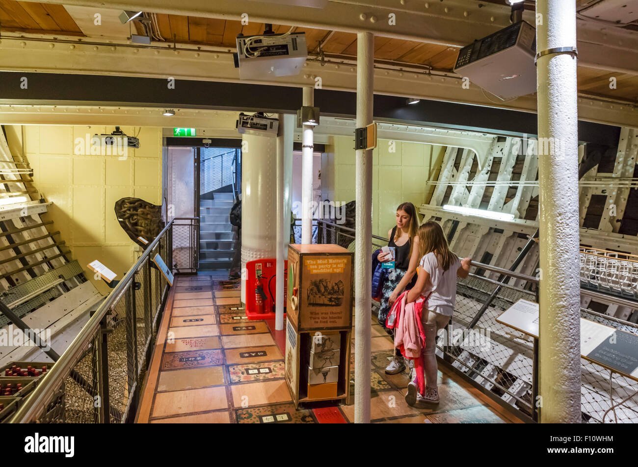
Marc, she is a composite clipper with teak planking on an iron frame. The steel spars suspending her are welded/bolted to her frame. When you tour her now, you enter through the hold and they explain that metal bits that you see painted a different colour are not part of the actual ship. I agree that it is much nicer than her old display. This picture shows how fancy the hold is now.
- 444 replies
-
- 3
-
-

-
- Cutty Sark
- Revell
- (and 2 more)
-
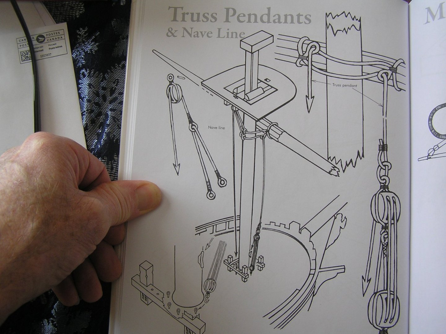
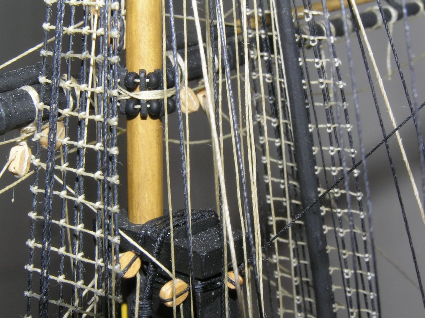
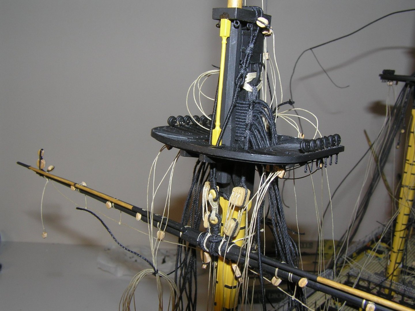
Bill, The weight of the lower yards is borne by their jeers and their sling, see PLAN No 8 (from outer space?). [As an aside, I had that plan pinned up at my desk at work for many years. One day someone who was talking to me asked, "What IS that anyway?] The yards are restrained to the mast by the truss pendants, see Fig 171 (the pendants don't appear to be shown in PLAN 8). These pendants, when loosened, allow the yard centre to move forward away from the mast. This allows the yard to be pivoted slightly farther around before its leeward arm hits the leeward foremost shroud, allowing the ship to sail a little closer to the wind. Topsail and topgallant yards have parrals, see Fig 139, to allow them to slide up and down the greased masts. The sprit topsail yard also employs a parral since it must slide in and out along the jib boom. The spritsail yard has no parral as it remains in place, see Fig 167. For model building purposes, I drilled small holes in the masts and yards and used pieces of brass rod to locate the yards. The rods are invisible after rigging. I made parrals from seed beads and little slivers of shaped maple. It was relatively simple to lash these to the yards since yards were attached by the brass rods. Here is an example. The topsail yard is lowered because I am rigging "bare poles". Please excuse the dust.....🙄
-
Yes, that's correct. Don't forget to tie the main buntlines to the bitts before adding shrouds, because the area gets caged in as you can now imagine 🙂
-
HaHa!! We love watching Jeopardy! (I already knew the names and purposes of most of the lines before the build)
-
Actually I read that the newer Revell Wasa kit is fully up to date. It looks beautiful; I nearly bought one but my stash was already a size for the years I have left!
-
Yeah, the area behind the foremast is a particular problem because it is boxed in by shrouds on each side, and many lines running up from the forecastle after railing to those blocks you mention under the fore top. To make it worse, there are also some lines running for the bitts aft of the foremast, up to blocks under the main top. For the fore top, look at Longridge Plan #8. Reading the lines passing through the blocks from left to right, we have the course leech, spritsail brace, two course buntlines, and the sprit topsail brace. On pg 266 we see these all originate from beside the belfry (in the same order to avoid criss-crossing on the way to the blocks). To estimate the lengths needed, the leech line goes out to the foreyard end, the buntlines go to intermediate locations on the yard, spritsail braces go to the ends of the spritsail yard hanging below the bowsprit, sprit topsail braces to the ends of the sprit topsail yard hanging beneath the jib boom. I rigged without sails and so just passed the leech and buntlines through their blocks and hitched to the yard. If you plan sails, they'll need to reach the leech and the foot of the fore course. Plan 7 shows all of these lines and buntline block locations on the yards, albeit in a busy way. As for the main top blocks, the main course bunt lines, two each side, originate at the bitts aft of the foremast (see pg 266 and Table pg 269), pass from forward to aft through the double blocks under the main top, then go to buntline blocks scattered along the main yard. You can estimate the lengths. The main course leech lines have tackles with the fall belayed to the bitts aft of the main mast (pg 267, Table pg 269); Longridge mentions deck ringbolts aft of the main mast (pg 251) and checking on my model I see I added two more eyebolts for these, one each side of the pair you already added for the mizzen stay and preventer. Sorry I forgot these! I used a ruler to add up all the distances traversed by each line, added a little extra, belayed on deck, passed through the bocks then coiled until needed (see my pic in post #742).
-
Marc, it's because the kit includes the patented Heller shroud/ratline jig. The masthead mounts at the top corner, and depending on which mast it's for you wind threads around labelled notches and put dabs of glue at the intersections. Then you mount the masthead and shrouds. I didn't use it.
-
Actually Revell has a kit for Thermopylae. I think it's mostly a rebranded Cutty Sark but maybe there are differences? You can find it on ePay.
-
Bill - are you sitting down? I believe I rigged about 310 blocks on Victory and that's without sails....🤪 and don't forget deadeyes I just made a quick rough count at 224. OC - my wife used to shake her head when I showed her the details I was working on, and that's exactly what she said it must be 😃
-
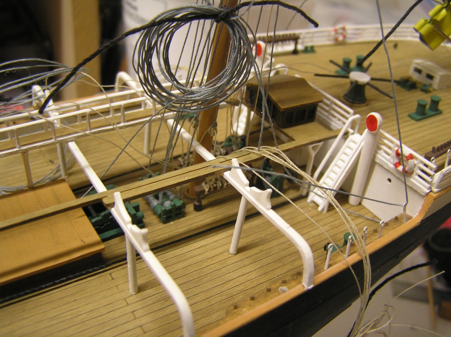
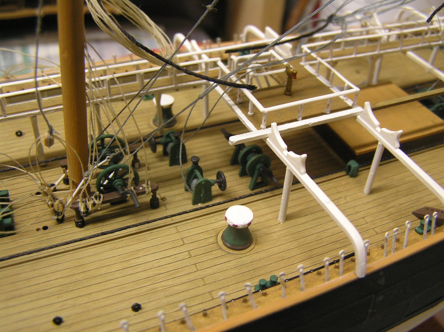
At long last I have added the lower and topmast stays to the jigger mast. I braced the jigger from aft to allow these to be tautened in the correct position. I've also coiled up some groups of lines to reduce the mess somewhat. I like the look of the "rigging screws" on these stays at the foot of the mizzen. Here we see the pump added afterward. The large holes remaining are for two brace winches, not yet rigged. Once all the blocks are on the mizzen it can be glued in. Here we see the machinery at the foot of the jigger. The port lower capstay is threaded through its rigging screw at the lower right. I got that far and realized I have not figured out what to do with all the shrouds and backstays. You know how all the ships seem to have several seizings all painted white? They need to be between the ratlines which are spaced at about 1/10 inch in this case. I need to find some un-fuzzy white thread because I don't want to fiddle with paint here. Need to make a clip-on paper template to plan ratline locations and hence locate seizings. Here is where the chickens come home to roost, because I did not get all the rigging screw heads accurately aligned.


-
A quick note Bill; the topmasts can only be pushed through the cap from below, as I recall. You must have them in place when you glue the caps.
-
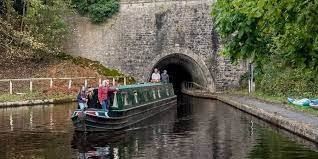
Just reading on-line about the canal. Sounds fun! I smiled seeing the Chirk tunnel; recalled to mind Hornblower helping to "leg" a canal boat through a tunnel on his way to assume command of "Hotspur".
-
Last time we were in London we boarded a narrowboat and voyaged through "Little Venice" and past the zoo to Camden Market for lunch. Great fun!
-
High of -9C (16F) today, down to -20C (-4F) tonight. Warmer on Sunday then back to cold. It's been a very poor winter so far; not much cold weather and very little snow. The Rideau Canal has not frozen enough for outdoor skating yet and the x-country ski trails are short on snow 😭. I was out yesterday and the tracks are very glazed due to recent thaws; makes for great downhills but hard on the grip wax. Sigh. They forecast a "large snowstorm" last weekend which missed us. We are apparently set to just miss another. Sigh again. But yes, I can get some work done on Preussen.

-
Just from modelling and reading I'm afraid. I've never sailed anything bigger than my dinghy (Bombardier Invitation) other than steering "Royal Clipper" one evening.😀😀😀 (Definitely a bucket list item!!). If I appear to be an expert on "Victory" it's because I have Longridge semi-memorized 😉. Sharing is what this site is for. I love seeing other models coming together, especially Victory, and hope to help others spend less time than the hours and hours I spent just thinking as opposed to rigging!
-
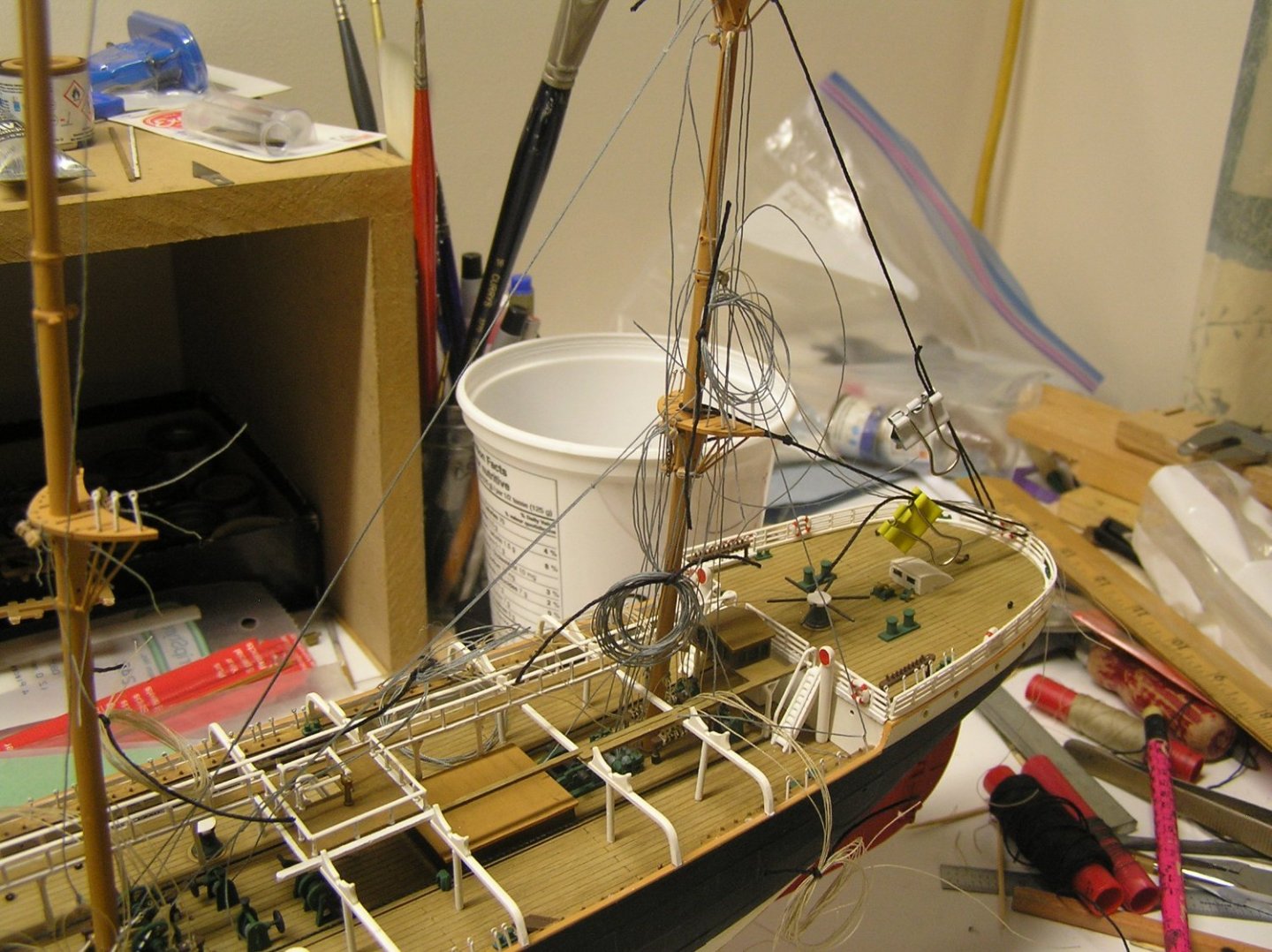
I looked through my old pics to see again what I did. Here is a photo from early 2017. The jeers, sling, and truss pendants/nave line are rigged before the shrouds had deadeyes, for access. My thinking was that any mast movement when aligning it with stays and shrouds would not affect, ie slacken, anything just running up and down the mast anyway. Also seen are all the buntlines, clewlines. sprit braces etc that pass under the top, already tied down at deck level to rig in reverse. Of course, the yard was equipped with all blocks and footropes before mounting it. I forgot to lash the boom ends, so I just never did. As an aside, I started running into the "server error 200" while attempting to upload pics yesterday. This pic wouldn't upload either so as suggested in the "server error 200" log I submitted this reply with text only, then clicked "edit" and tried an upload again, which worked obviously.
-
At all 3 masts, there are two deck eyebolts and two cleats on the front of the mast labelled for the truss pendants. Referring to Longridge pg 240, you see the diagram of the pendants themselves ending in double blocks.Two more double blocks are hooked to the deck eyebolts. The pendant tackle starts at the eye at bottom of the upper double block, reeves through the upper and lower blocks, and the free end (the "fall") is tied off to the cleat. So you are using all four of the marked positions, in the case of the mizzen #78. It's a similar story for the driver boom topping lifts #93. Referring to Longridge diagram pg 255 and text pg 256 "Topping Lifts", the topping lifts themselves end in double blocks. This is rigged in a tackle with a block at the deck eyebolt, and the fall is tied to a pin on the mast ring. You can see this in the Figure, the 15" double and 15" single aligned at the lower right. Thus again, all four positions marked 93 are used. Now that you are at the rigging stage I recommend you read and re-read Longridge and make notes. That's what I did to keep track of all the blocks and tackles.