Ian_Grant
-
Posts
2,156 -
Joined
-
Last visited
Content Type
Profiles
Forums
Gallery
Events
Everything posted by Ian_Grant
-
 Hi Kevin, I used Amati thread. They have a larger size range, which is needed for things like shrouds and the main- and fore-stays. The thread cost a bit, but with brass etch, wood blocks, and deadeyes to buy already, you just tense your stomach muscles and pay up 😃 Great work on your Cutty Sark!
 -
HAHA!! I love the little animation; he even pauses to give the can a shake LOL.
-
Looks very nice. Love the dog kennels! 🐕
-
Kevin, your woodwork looks great! Awesome painting.....
- 444 replies
-
- 1
-

-
- Cutty Sark
- Revell
- (and 2 more)
-
Marc - To be honest I haven't actually looked at the blocks in my SR; mostly the sprues are still in the plastic bags. I was just assuming that they are similar to those provided in the Victory. If they are, and if you like, I could send you my Victory blocks for postage.
-
I haven't started mine yet, not will I for years, but one thing that bothers me about the deck area is the smooth featureless inside face of the bulwarks. I plan to add some evergreen strips to jazz it up a bit by adding some depth and shadows. I see the model referred to above also has no ladder to access the upper poop deck, which has been discussed in the forum too. How did they get up there? There seems to be a ladder just lying on this model's poop, or is that a skylight? Another thing that surprises me is Heller's arrangement of SR's crosstrees vis-a-vis the top- and topgallant masts. It just looks odd to me.
-
Daniel, great to see you starting on a non-Victory kit! Love the guns. Looking forward to seeing it develop into another masterpiece.
- 64 replies
-
- 3
-
-
- Revell
- Constitution
- (and 1 more)
-
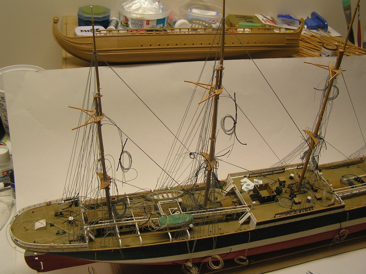
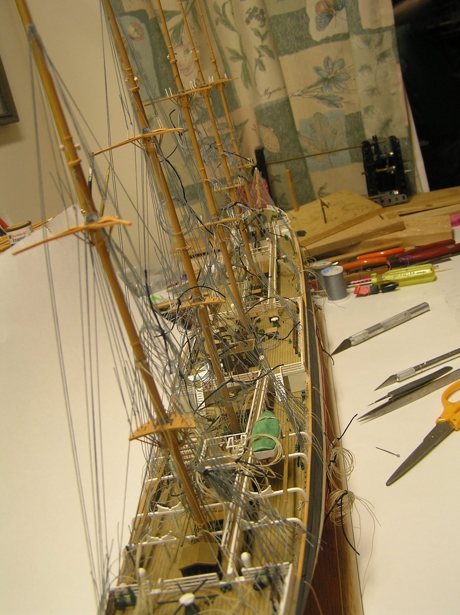
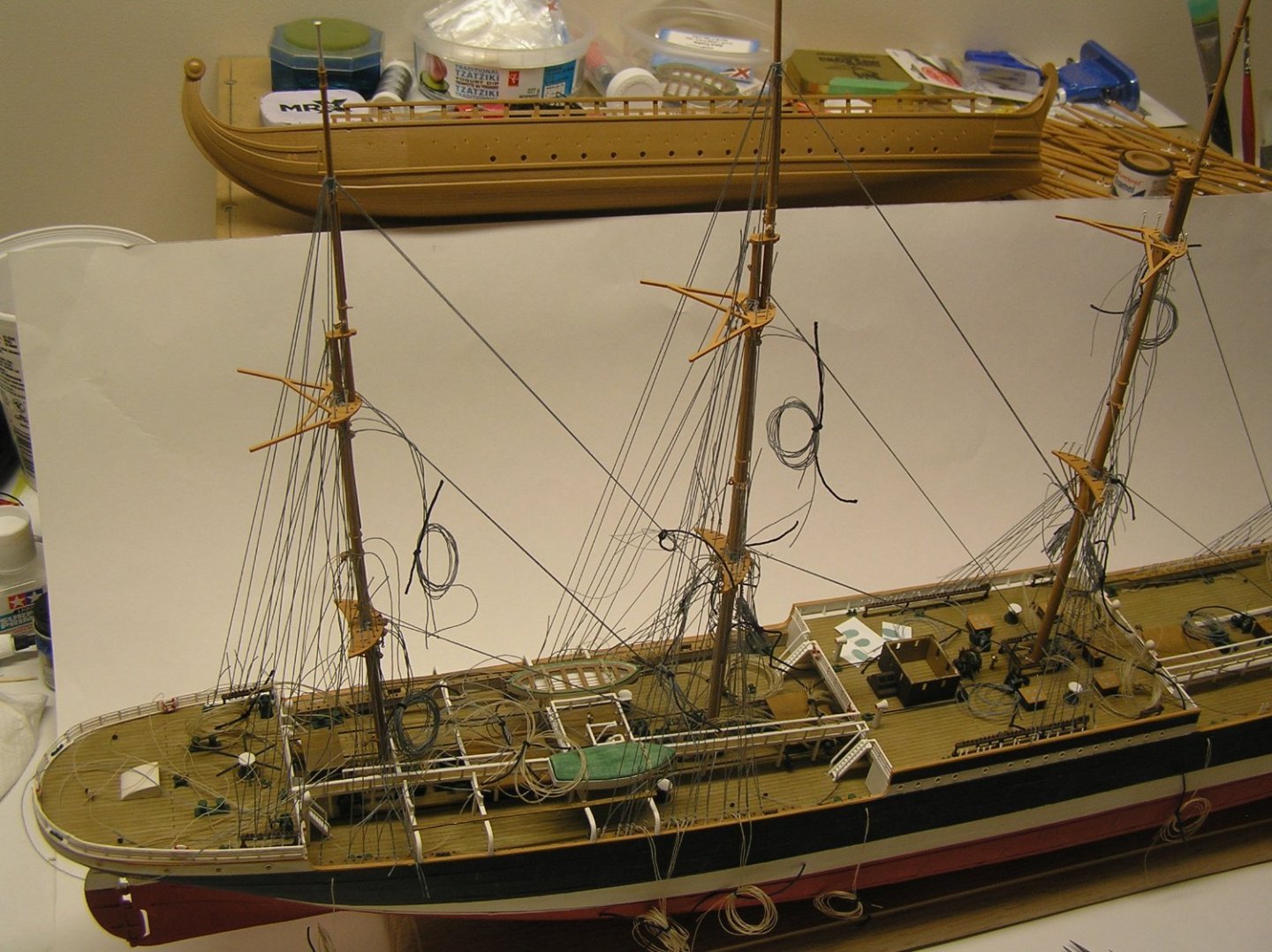
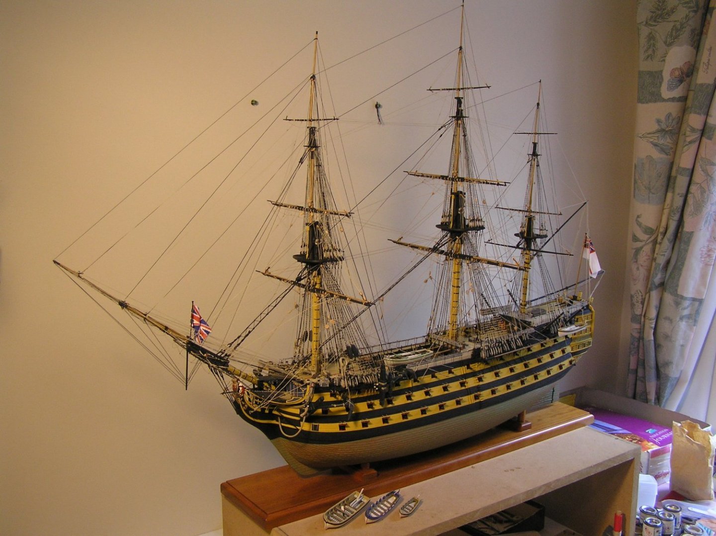
All standing rigging (except stays and backstays on the royal) complete on mizzen and jigger masts. There sure are a lot of backstays on these steel ships - at hounds, fixed yard bands, and mast caps as well as all the usual backstays. No wonder they could drive them so hard. I added the forward-most boat on each side as they are now behind a wall of backstays. I decided to tie on the upper braces terminating at the mizzen bulwark pins after all; these can be seen coiled in the first pic, emerging between the mizzenmast shrouds/backstays. I will now do this at each mast in turn before adding its backstays, for access reasons. It came to bother me that the wheelhouse windows were empty cavities whereas all the skylight ports are painted a sky blue, so I managed to pry off the wheelhouse roof. Plan is to paint some styrene sheet sky blue and glue on inside the walls then reapply roof. Sadly my sky blue paint has dried up so off to the hobby shop, sometime........you can see some sheets lying to port of the wheelhouse with blobs of what I thought was the correct paint but it was too green.

-
Bill, you're just flying through this, as usual. Looking good!
-
I'm a little disappointed that no one mentioned the - gasp - plastic Heller Victory. It is hands down the most accurate kit of Victory on the market. At 1/100 it is a reasonable size for detail without taking up too much floor space, and there are seven sheets of brass etch available to enhance the build. See the several build logs on the forum. Just sayin' 🙃 Edit: Thought I would add a shot of mine on the bench just after completion.
- 36 replies
-
- 11
-
-

-
Twahl, looks like I get to be the first one to pull up a chair and follow you. Great start, with gunport lid rope holes drilled out! Molded all in one colour? First time I ever heard of that. Must be new. Or maybe not so new, I bought my kit with some parts molded in a vivid red in 1982 but didn't start it for decades. I enjoyed your comment about your wife not tracking your expenditures, for now 😄. I painted mine before they decided that she was painted wrong so mine is yellow ochre. It's your model so you should do whatever pleases you. You mentioned you have Longridge. He gives rope and block sizes for each rigging line in his text. Note that he follows the marine custom of giving rope size in circumference. All you have to do is divide each mention of a rope by 100 x PI. Or you can PM me your email address, if you like, and I can send you a spreadsheet I made with all the rigging line and block scale sizes. Bill and Kevin took a copy but don't know if they really used it 😕. I compiled it to save me flipping through the book all the time. Good luck with your build! I will enjoy reading your log, as with all other Victory logs.
-
Mr. Midshipman is the first in the series, chronologically (they were written out of order, amazingly enough).
-
Yes, I believe I glued two blocks together and tied them at top, middle, and bottom, as you say.
-
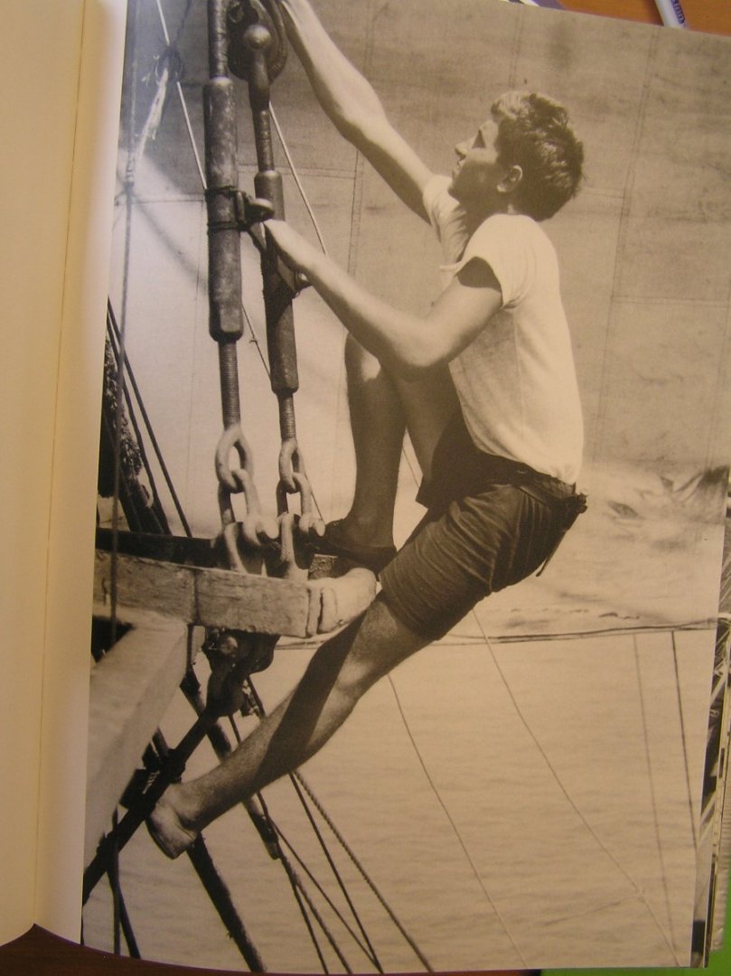
Bill, that's right. Keep going! By the way I was just looking through my copy of "last of the Windships" to see if there was a photo of how the boats were lashed down and I came across this shot of someone ascending the futtock shrouds. God knows how he got his right foot onto the top; my gangly knees would be a serious hindrance! No safety harness of course.............🤔
-
So did I. Looking forward to reading it; hoping it will help me decide how to configure my SR's stern and 1/4 balconies (when I get to it). I opted for the cheapest delivery from Chicago and the quoted receiving date is mid June (!!?). I could walk to Chicago and back with it in that time. There's something about USPS and Canada, it's fabulously expensive and/or slo-o-o-ow.
- 2,699 replies
-
- 5
-
-
- heller
- soleil royal
- (and 9 more)
-
It's just a piece of rope spliced into a continuous loop, ie like a grommet or ring as Longridge says. It's made to fit tightly round the topgallant mast and is pushed down until it hits the shoulder on the top of the hounds. It just acts as a "pad" between the 1st pair of shrouds and the "sharp" edge of the wooden hounds to prevent abrasion on the shroud fibres. On a 1/100 scale ship it can be omitted. I did. A deck quoit is a rope ring which used to be used as a game on passenger ships, much like ring toss. Being aboard a ship, rope is a naturally available material. 🙂
-
That's a model??!! 😲😮 Fantastic looking rope! Sorry Chuck for spreading lies ..... 🤐
-
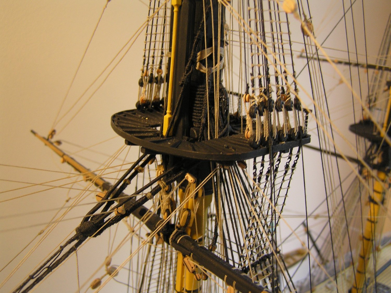
Bill, Saw your pictures above, and I can see why you rigged the topgallant shrouds the way you did, given the treatment of the topmast shrouds and futtocks, but in actual fact the topgallant shrouds are rigged differently. Instead of being tied off at the topmast futtock stave, they pass between the topmast shrouds above the stave then carry on down inside the shrouds to the mast top to which they are attached by pairs of thimbles, and lashings, to the deadeye strops. Longridge describes this in words on pg 233. There is also a picture showing a topgallant stay lashed to a deadeye strop on the mast top. I think you have Petersson too? He has a nice picture on pg 11. Here's a pic of my model's main top. You can see the topgallant shrouds inside the topmast shrouds (smaller black lines with no ratline clove hitches) and the thimbles and lashings at their feet. Hope I caught you before you did another mast! 😉

-
Twahl, Unfortunately I believe I read here on MSW that Syren no longer sells rigging line. You can however buy their rope walk kit and make your own, or just buy some other make. I used Amati thread and was happy with it at the Victory's scale. All the diameters required are available. I agree with Bill about the Longridge book, obviously since I've been quoting it to him all along! 🙂
-
Hello Twahl; you're on the same path I followed - a Heller Victory after 30 years away from models! You're right, some of the wood blocks on the market are very square-ish and unrealistic. Have you looked at Syren's offerings? They make very nice blocks which I used on my Victory. Having said that, they do add a fairly high cost to the build. RJ's filing method will make the Heller blocks usable as far as stropping goes, but IMO the sheaves are molded far too small and the openings are too large. They are nicely shaped blocks though. When/if I get to my Soleil Royale I will weigh the time and trouble of modifying and painting Heller's blocks vs the cost of wood blocks. Bear in mind that Heller's deadeyes are also unusable so there will be an after-market expense to replace them anyway! Looking forward to another Victory build log! 🙂
-
Hello Bill. As you predicted here is the answer. Those are the two separate jeer block lashings which pass through the cleats on the mast. The rope you see seized around the bottom of the lashing is the jeer block strop, from the upper jeer block. See pg 241 and Plan 8. 🙂
-
Geez Bill that's just my opinion. Try them out, some are ok. Peck's Hornblower movie is very enjoyable and covers three of the Forrester books in brief. Sort of. I own a copy. Are you aware of Alec Guinness in "Damn the Defiant"? Another great classic movie. I own a copy. I assume you have seen the recent "Master and Commander" with Russell Crowe? A great movie based on one of O'Brien's books. Again, I own a copy. Keep your eyes peeled for the guy sitting at the head as the ship comes at you out of the screen during a storm!
-
Yeah, well, that series started off looking great (intro episode, and the episode aboard the Renown) but soon veered off in new plots that IMO are far weaker than the books. And sometimes ridiculous (landing in France episode). The classic movie with Gregory Peck as Hornblower is far better.