Ian_Grant
-
Posts
2,156 -
Joined
-
Last visited
Content Type
Profiles
Forums
Gallery
Events
Everything posted by Ian_Grant
-
 I liked the jig too, but how about just printing the actual ladders and painting them to save the headaches? I did this at 1/150 scale (I CAD'ed them, my brother printed them) for Preussen 'cause the kit ladders were unusable. Mind you this is a plastic kit.......
 -
Looking great, "rookie"! Really like the tryworks.
-
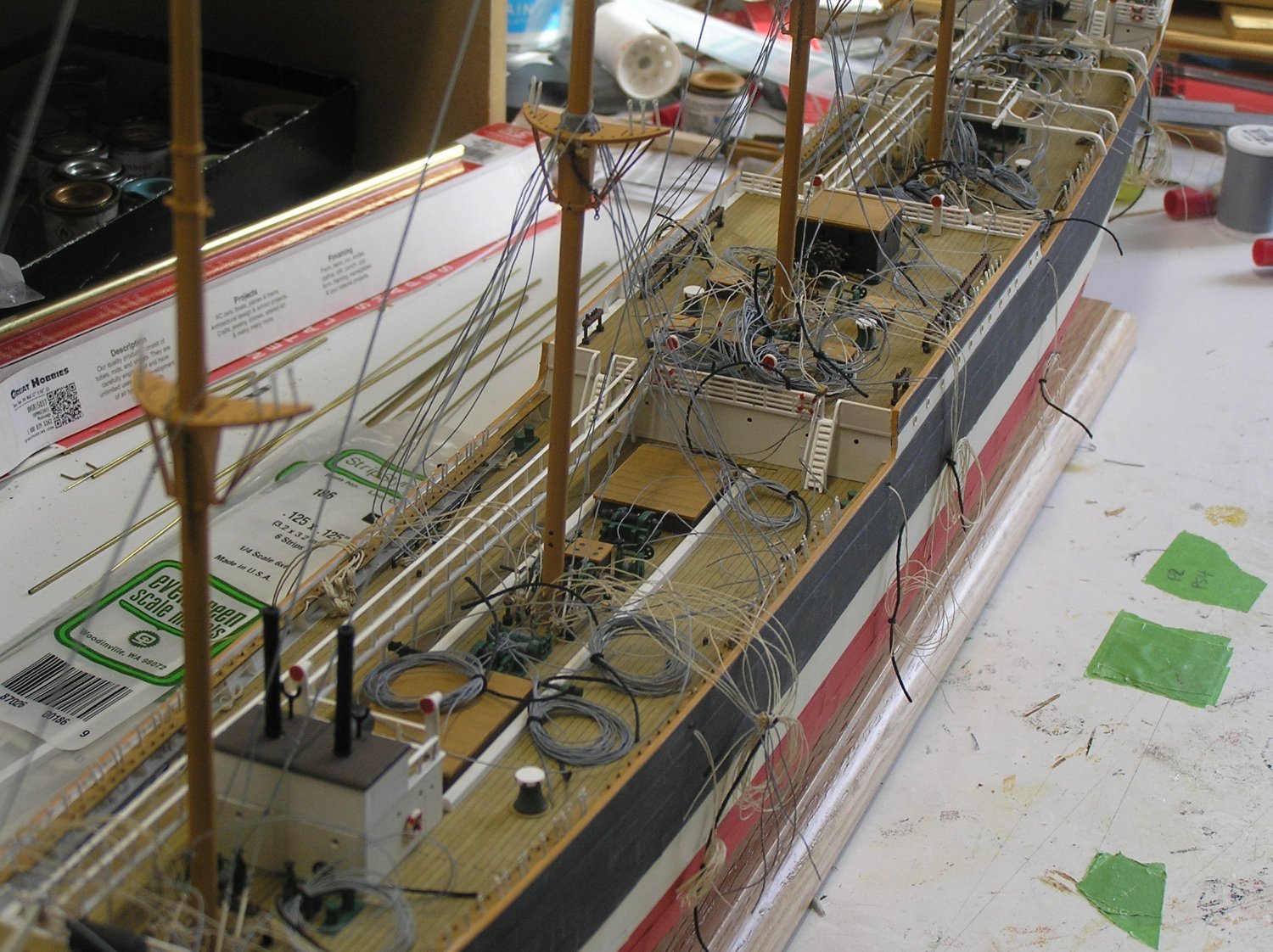
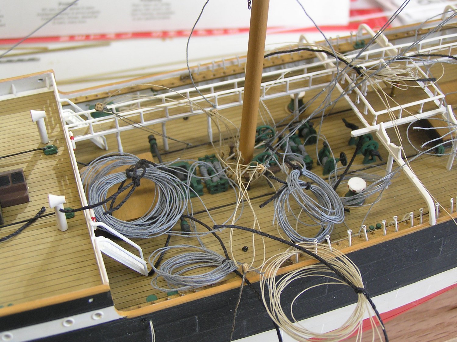
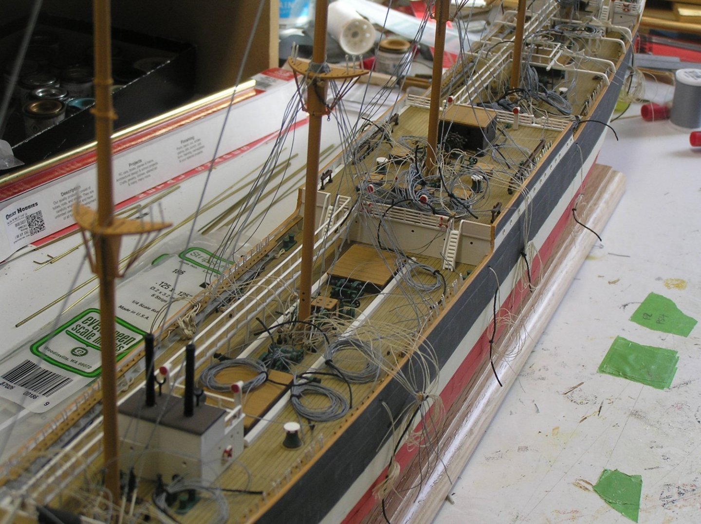
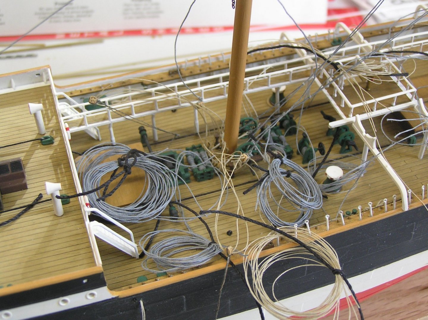
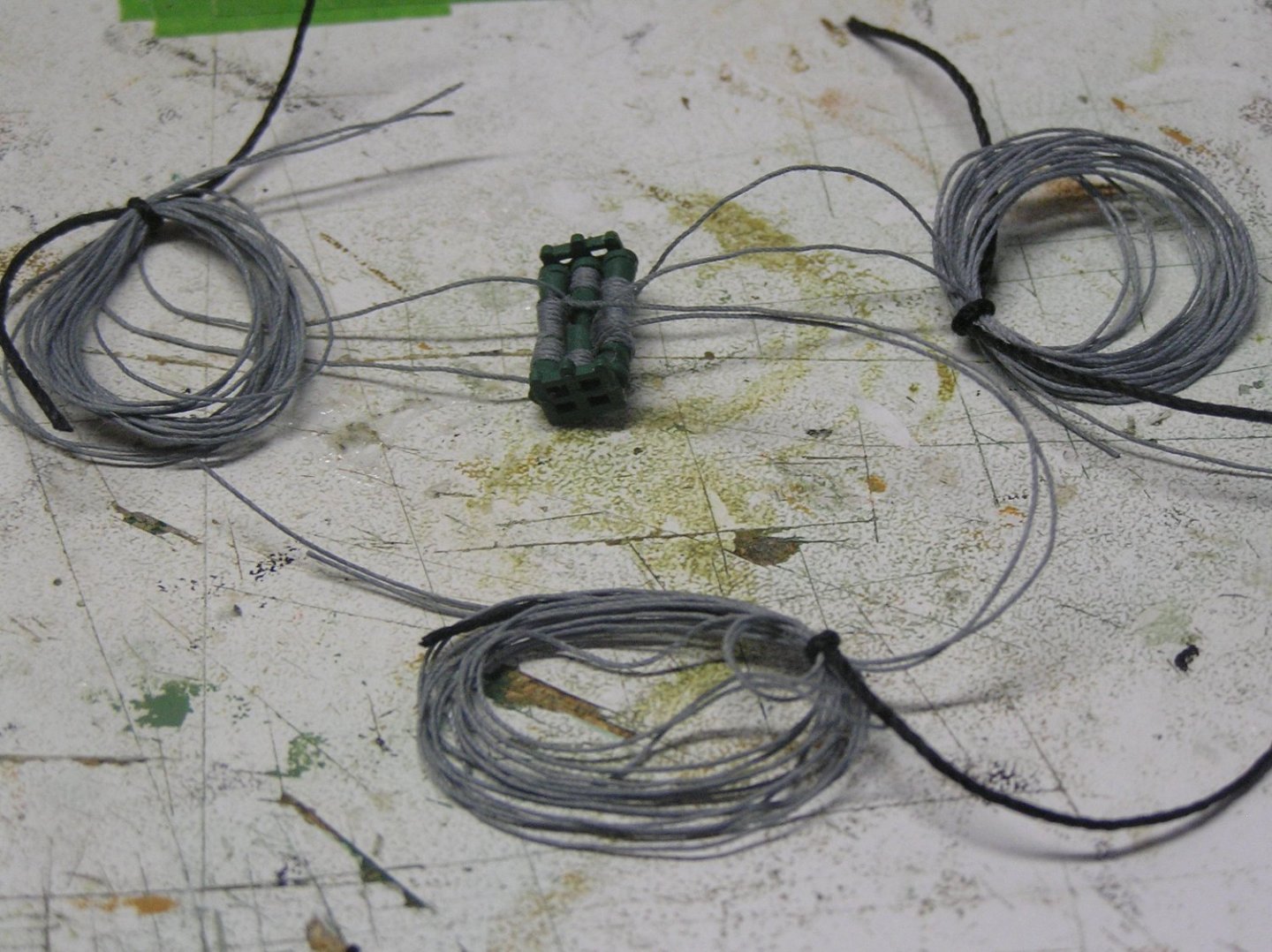
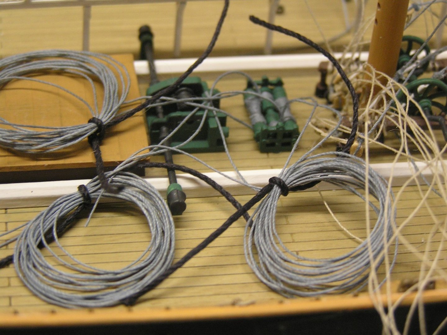
In a moderate burst of energy, I wound threads on the remaining brace and halyard winches. All 17 are now glued to the decks with threads coiled. No more empty holes in the decks! The only remaining parts are the yards, four boat davits, and two walkway planks beside the boats. The coils are getting a bit ridiculous, I must do some real rigging soon before it becomes a hopeless tangle. The foot of the mizzen, with Jarvis winches both before and abaft.
-
Veszett, there are recent printings. Mine is a William Collins 2014 edition.
-
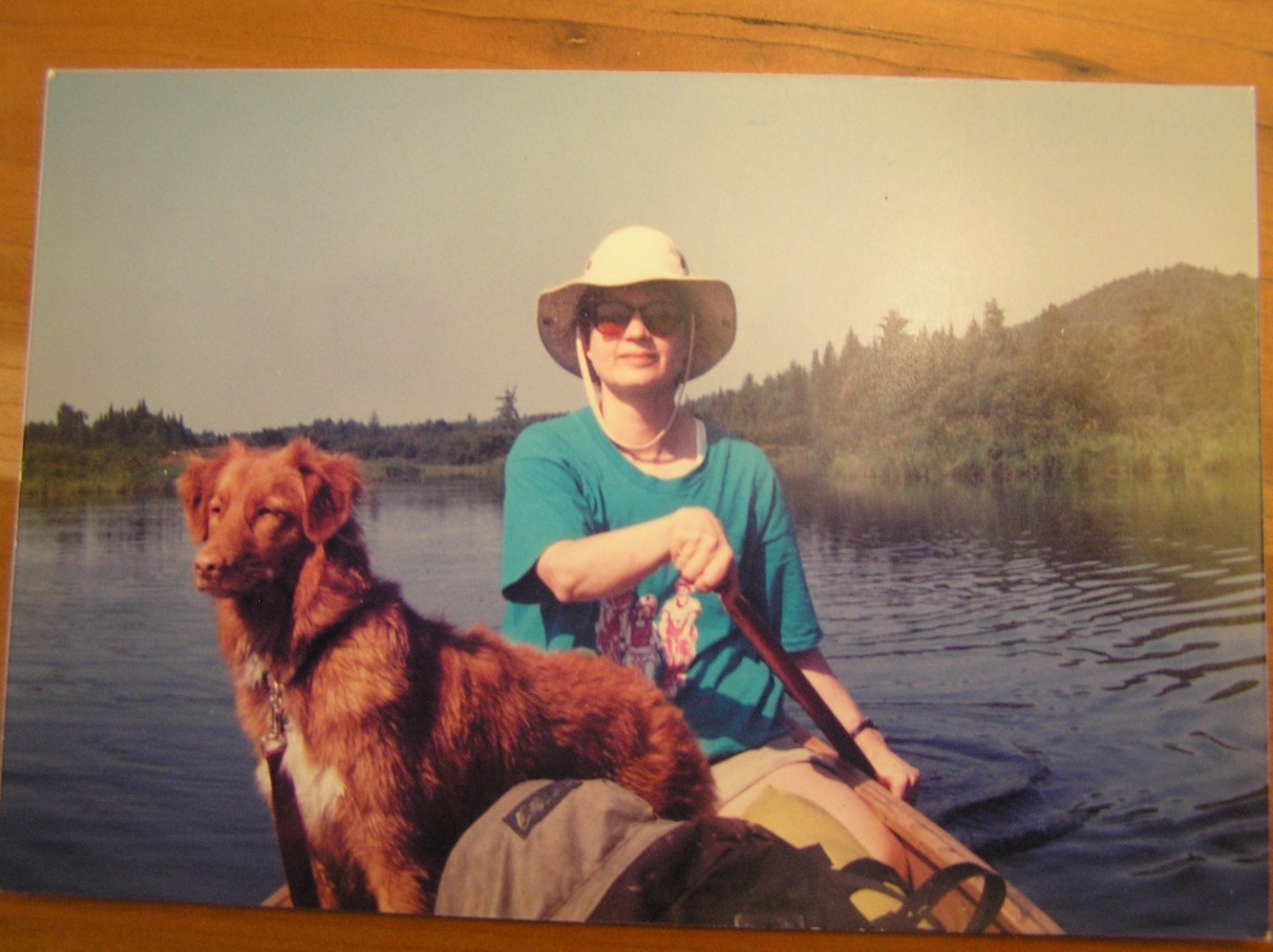
Kevin, yes they are beautiful; there's nothing cuter than a Toller puppy. They're easily bored because they have brains and to spare. Penny was very very smart; by the end of puppy socialization class she could do the "biscuit on the end of the nose" trick. She was a ball of fire at the dog park; loved to be chased. Not many could catch her. Many Tollers have slightly sad expressions, until they have some work to do then they have an air of intense excitement and concentration. LATER EDIT: I forgot to mention the key thing Tollers were bred to do; they "toll" which is lure ducks towards the hunter's blind. Something to do with their fox-like colouring and the way their bushy tails wave as they play around. It may sound unbelievable but we've seen it work on loons while on canoe trips. Penny loved to wade around looking for frogs in the evenings and time and time again we had loons hanging around off our campsite watching her (she was oblivious to them 😀). The record was 14 of them one night on a Killarney trip. One never sees more than two or three together normally, and I have no idea how they communicated the news. When Penny wandered away from the shore, the loons would bob around and be facing random directions but as soon as she reappeared they all pointed at her like compass needles. Fascinating to see! Don't know if they mentioned it in what you read but they also have what is known as "The Toller Scream". The breeder used to have annual gatherings for all her customers' puppies. When Penny was two years old 42 dogs showed up. They had a fun retrieving trial in the lake; a guy in a rowboat fired a starter's pistol then tossed a dead duck into the water. Whichever dog whose turn it was was then released to see if it would retrieve it (these were mostly just pets, not working dogs). But each time, 42 dogs would scream to be allowed to go. Deafening. 😃 Penny used to sit on the cottage dock and watch me if I swam, worried about me. Sometimes I would fake drowning, splashing my arms and calling her name. Then I would duck under, at which point she would scream and dive off towards me. I loved that dog! Still miss her. Here she is in the canoe with my wife, still damp from a swim at the portage mouth, on I think the Nipissing River in Algonquin Park. Digital photo I just took of an album photo from the old days 😀. Apologies for further digressing!
- 444 replies
-
- 4
-

-
- Cutty Sark
- Revell
- (and 2 more)
-
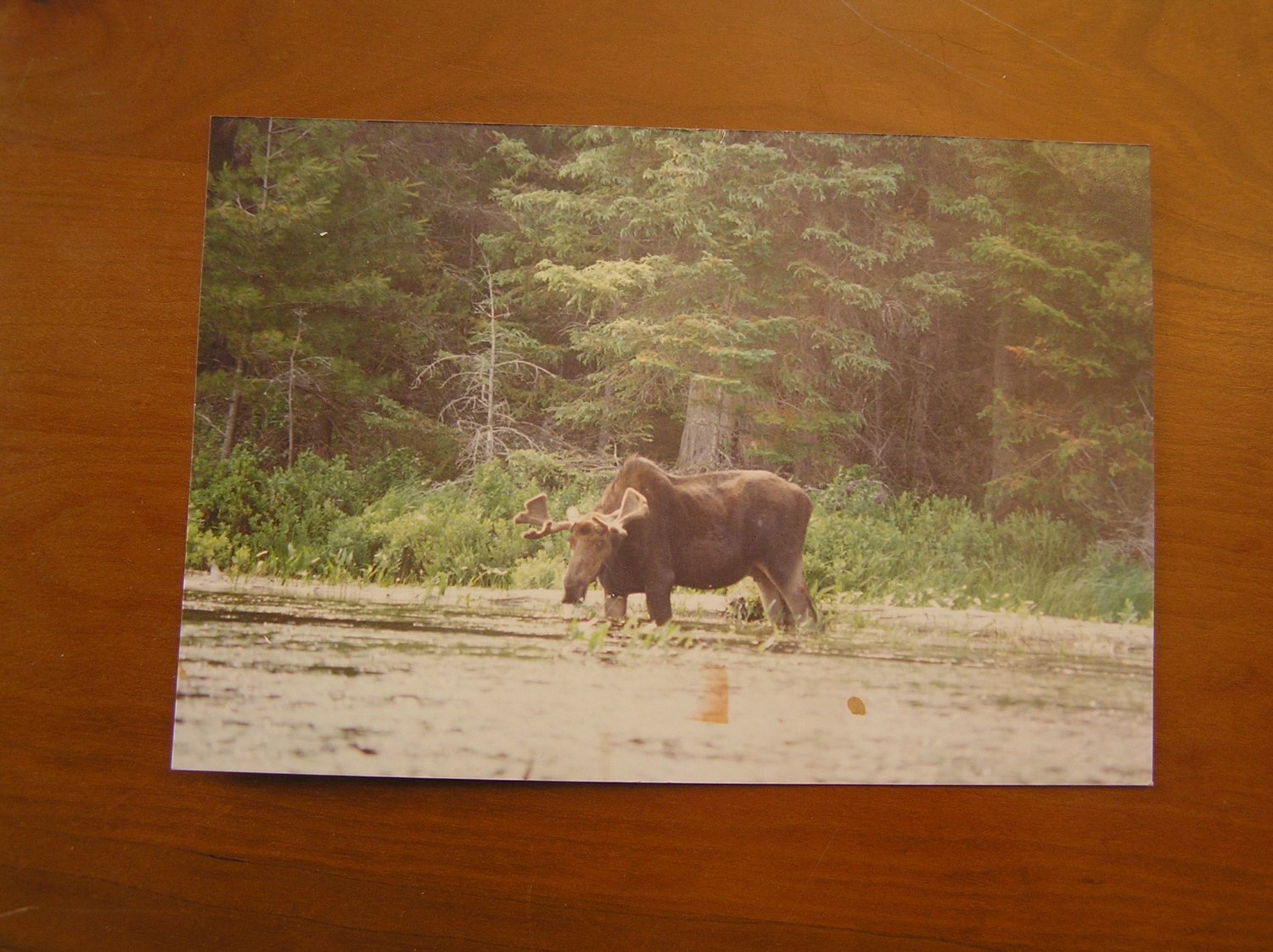
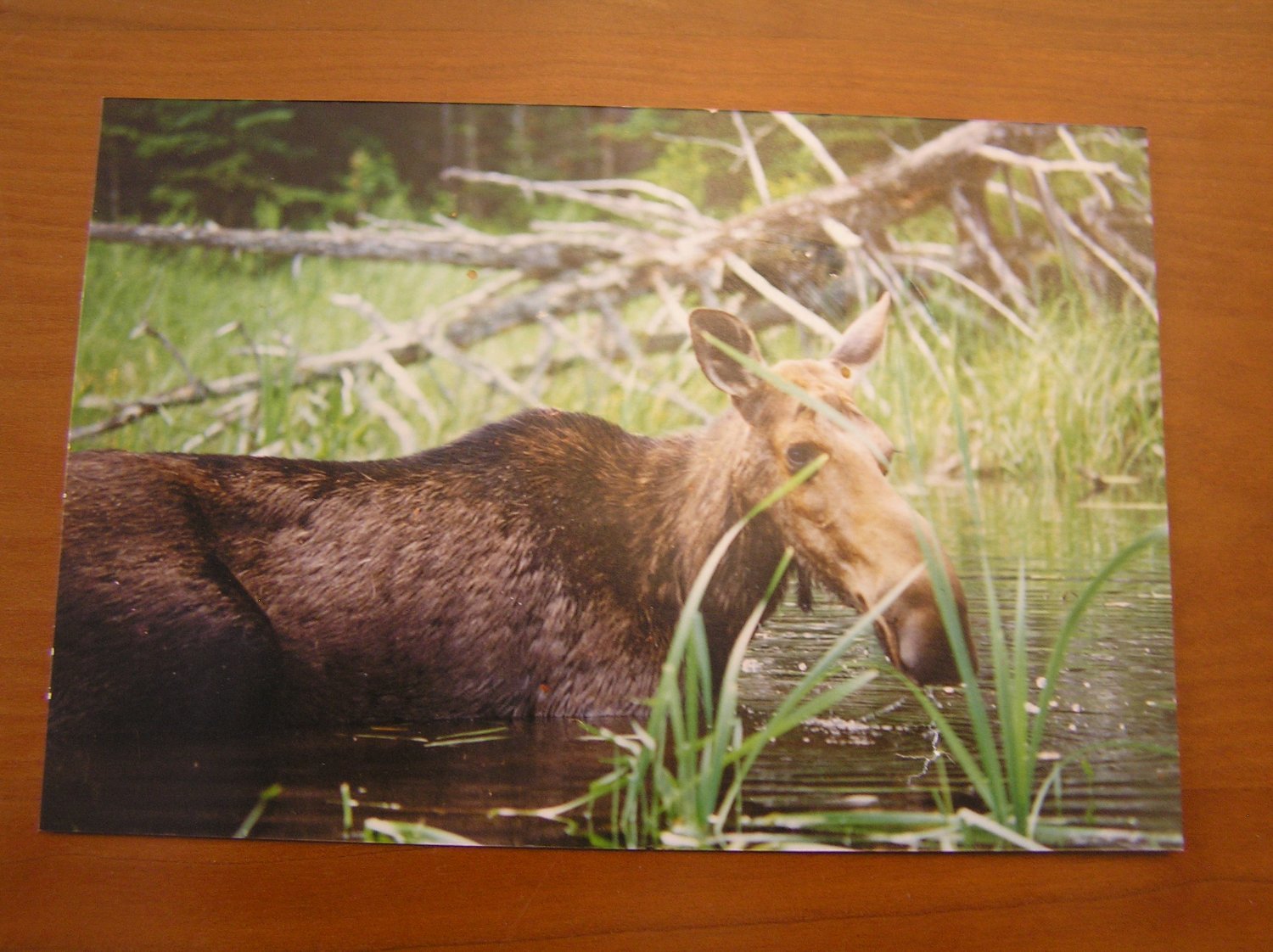
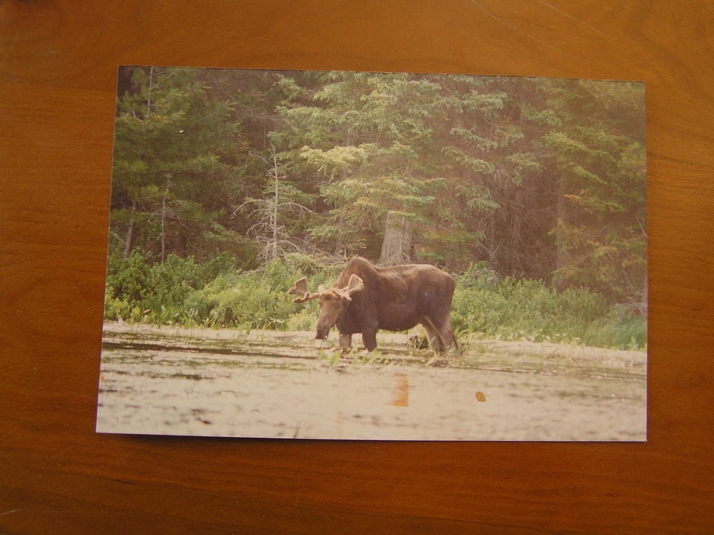
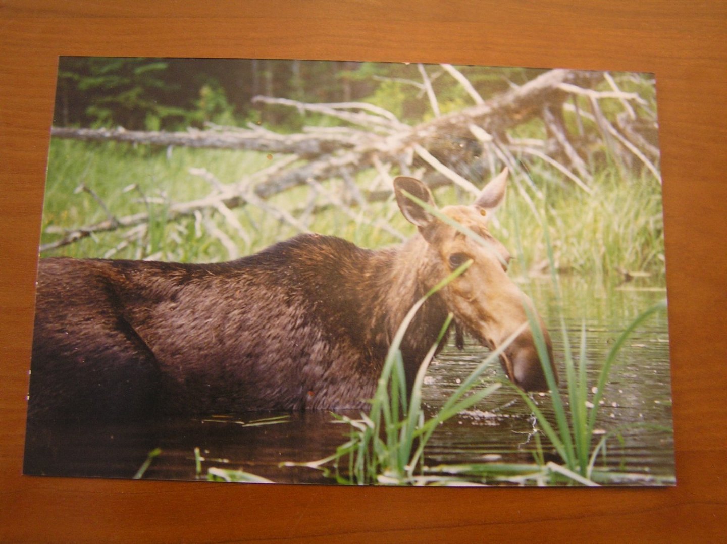
To continue the digression: we've seen many moose while on back-country canoe trips. They're impressive animals especially when standing on land - hugely tall. One time we rounded a bend to find two just clambering out of the water. One paused, looking back at us, to let a veritable waterfall of urine flow into the river, which of course we would be drinking out of that evening. 🙄 Another time I came to the rather cramped end of a portage to find a moose standing there munching on plants. I talked to her for a minute or two, with a canoe over my head, until finally she edged over just enough to let me drop the canoe into the water. She calmly stood there six feet away, eating as we loaded our stuff and departed. I had for many years a photo of her pinned in my cubicle at work. An extreme close-up you might say. We had a Duck Tolling Retriever, Penny, who loved to come on canoe trips. Darned if I was going to carry her food too, so from the first we got her "dog panniers" which we strapped on at portages. She carried her food and soft bowls, her first aid kit (porcupine quills anyone?), our first aid kit, and some TP. She would trot along ahead of us on portages, pausing to look back at each bend to check if we were still coming. One trip when she was very young I rounded a bend to find her in a staring contest with a moose who had been strolling our way on the portage trail. I stood there, talking to it, until finally it stepped off into the woods. Penny was glued to my legs for the rest of that portage, and glanced nervously into the woods as we passed the point where it had disappeared. 😄 Last story: on one trip we were paddling on a river and rounded a bend to find two moose calves enjoying themselves swimming around. Two ladies who had come in a canoe from the other direction had decided it was a great idea to get out to swim around with them! We stopped paddling and the breeze blew us to the shore. I remember saying to my wife, "Their mom must be nearby", then we heard snapping and crackling from the woods beside us. Mom emerged, heading directly at us. When they're walking toward you and you're sitting down, they are HUGE. But she swerved slightly and stepped past our stem into the water. Let me tell you, those ladies moved pretty fast too. We have done many canoe trips and you never know what you might see. Some other time I might tell you some black bear stories. We've seen lots of them too.😬 Later Edit: I dug out the old photo albums and found a couple of moose pictures. First is the usual view you get, them standing knee-deep as Kevin mentioned, eating as you paddle past. You don't go too near bulls like this if you can help it. Second is the one at the end of the portage I mentioned above.
- 444 replies
-
- 3
-
-
- Cutty Sark
- Revell
- (and 2 more)
-
Nice! I'm interested in that cooling fan because I'm toying with building an RC galley using servos for rowing and sweep servos may need some active cooling. Is your fan for the ESC, or the motor, or both?
- 15 replies
-
- 2
-
-
- lumber hooker
- Oscoda
- (and 4 more)
-
Festool shop vacuums - a quieter option
Ian_Grant replied to druxey's topic in Modeling tools and Workshop Equipment
I have bought a lot of my tools on Black Friday, or at least the Canadian equivalent. Got an incredible deal on my air nailers, and on my portable table saw. In the case of the table saw, Home Depot gave me their "10% less than competitors" price, below Canadian Tire's Black Friday price!!!! I was a happy camper. My old shop vac just happened to pack it in shortly before another Black Friday. -
Beautiful work, clean and crisp.
-
Good God!! How do you work so precisely??!! Colour me green..............
- 2,699 replies
-
- 8
-
-
- heller
- soleil royal
- (and 9 more)
-
Hi Bill, those are actually misnamed booms for the main lower studding sails. They attach to the eye and crutch on the main channels as shown in step 28 "Various Assembly" (also shows the boat davits). There should also be booms for the fore lower studding sails however Heller omitted them. They don't seem to attach permanently to the fore channels, probably because attempts to stow them swung back like the main booms would be obstructed by the sheet anchors. I presume they were rigged when needed. I made two (lengths are in Longridge) and lashed them down between the boat skid beams.
-
Interesting! Thanks Chris. Boy, that's a slow-moving training video; I can imagine the audience falling asleep in a haze of cigarette smoke.
-
Chris......."sky lookouts"? Are those for the lookouts to rest their elbows on while holding binoculars to the sky?
-
Festool shop vacuums - a quieter option
Ian_Grant replied to druxey's topic in Modeling tools and Workshop Equipment
I bought a Rigid a few years ago after my old Shop-Vac burned out (again; their motors are junk quality). The Rigid came with a "muffler" which can be plugged into the exhaust port. It makes quite a difference although I think it is still loud. -
Plodding along. I find my tolerable sitting time at this is quite short which does not bode well for a quick finish. Still working on tying lines off at deck level. Pretty tedious. Added shrouds at another mast, and rigged another brace winch just to change things up. Three of these to go, what joy! Main issue is that I want to carry on from my experimental RC galley rowing mechanism (see below) to further testing which will need the pool open, and spring is coming..............
-
BIll, I don't think you're too far off the real thing although from books I have the real thing has them a little far apart too.😏

-
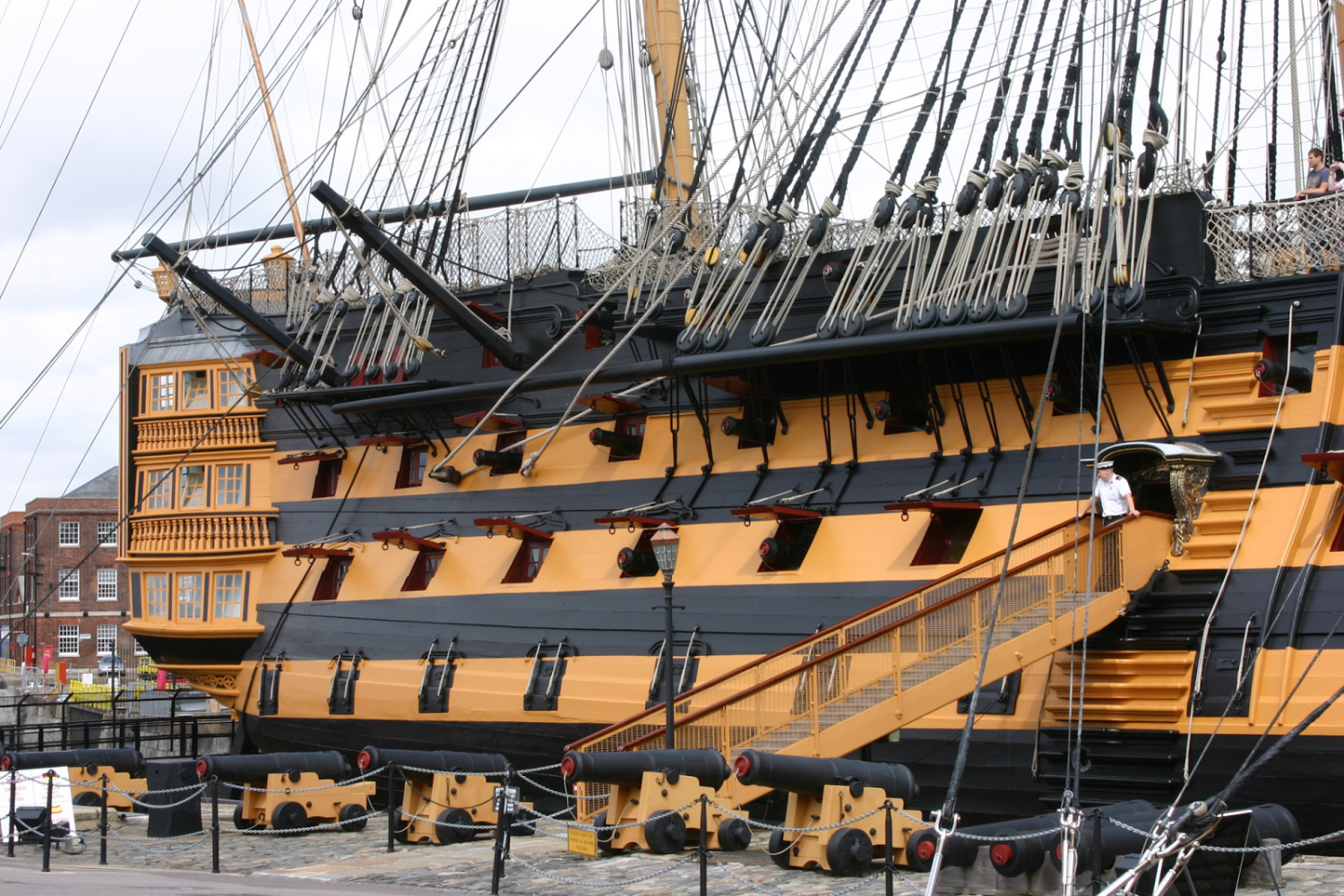
Wow I'd love to do that.......when I was aboard I wondered what would happen if I just did it......arrested I guess.... During Royal Clipper cruise they provide opportunity to ascend mainmast shrouds but only to the top. As this mast projects from the highest deck on the ship (thus lowest height above deck), and that side of the top is rigged through a lubber's hole as opposed to futtocks, it's not very exciting. Hope the "Cutty Climb" becomes a perennial thing.
- 444 replies
-
- 2
-

-
-
- Cutty Sark
- Revell
- (and 2 more)
-
Heller 1/100 HMS Victory - Question on size
Ian_Grant replied to Bill97's topic in Plastic model kits
Dear Prolny -- Just stumbled onto your post. This is pretty much a dead thread with few viewers (no followers); I suggest you post your question as a new topic in this category. Make the title indicate you want to commission a Heller build 😃. -
This article just published in the Toronto Star. Take a bow, plastic modellers! https://www.thestar.com/life/together/people/2022/02/27/model-citizens-hobbyists-explain-why-putting-together-plastic-kits-is-hardly-kids-stuff.html
-
- 7
-