Ian_Grant
-
Posts
2,156 -
Joined
-
Last visited
Content Type
Profiles
Forums
Gallery
Events
Everything posted by Ian_Grant
-
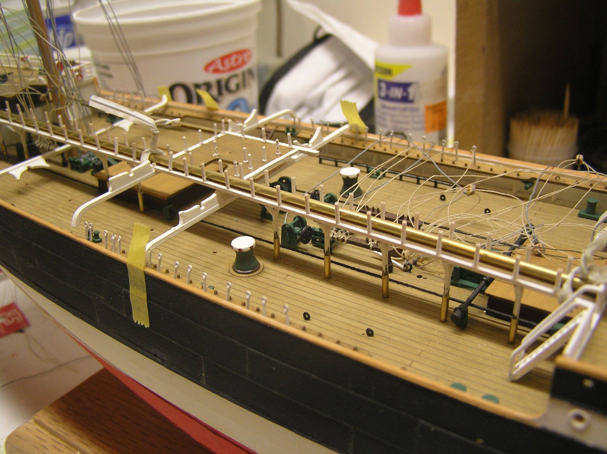
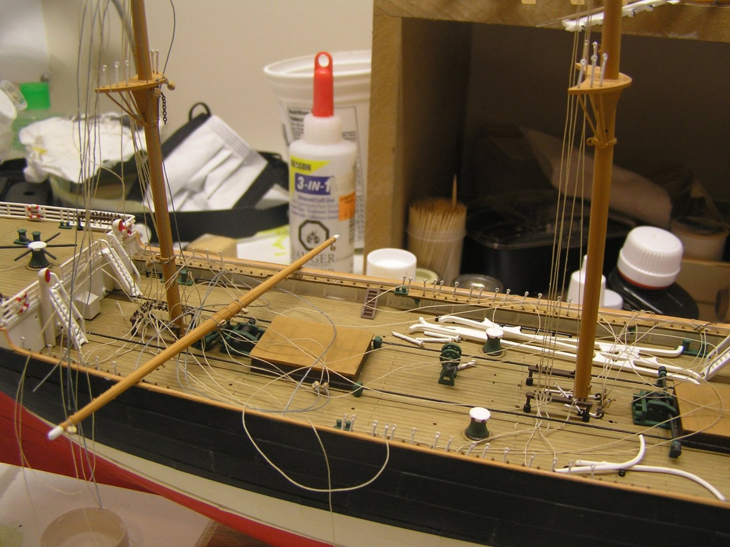
 Local hobby place had the required brass tube (for any Preussen builders, K&S 815037 1/16" brass tube with 0.006" wall whose ID is about 0.050" just right for catwalk support posts. I cut it into 1/4" pieces and deburred the ends. Had to sand some paint off the posts - I had painted them black according to Heller instructions but later changed to white so paint was a bit thick. Then slipped them onto the posts, placed catwalk back on ship, tweaked the brass "post feet" into place and locked with tiny drop of liquid CA. Here is a photo. The brass tube along the walkway holds it straight and at proper height at ends, while I adjust the feet. Note the centre island bulkhead is slightly lower than the poop deck bulkhead so there is a slight slope. Oh well 🤪. Now to remove it again and repaint the posts white (over the brass too). Now I'll need to pad the ends of the boat beams a bit, and lengthen their support posts too. The second one from the jigger mast is glued to the flying bridge; you can see the ends levitated above the bulwarks.
-
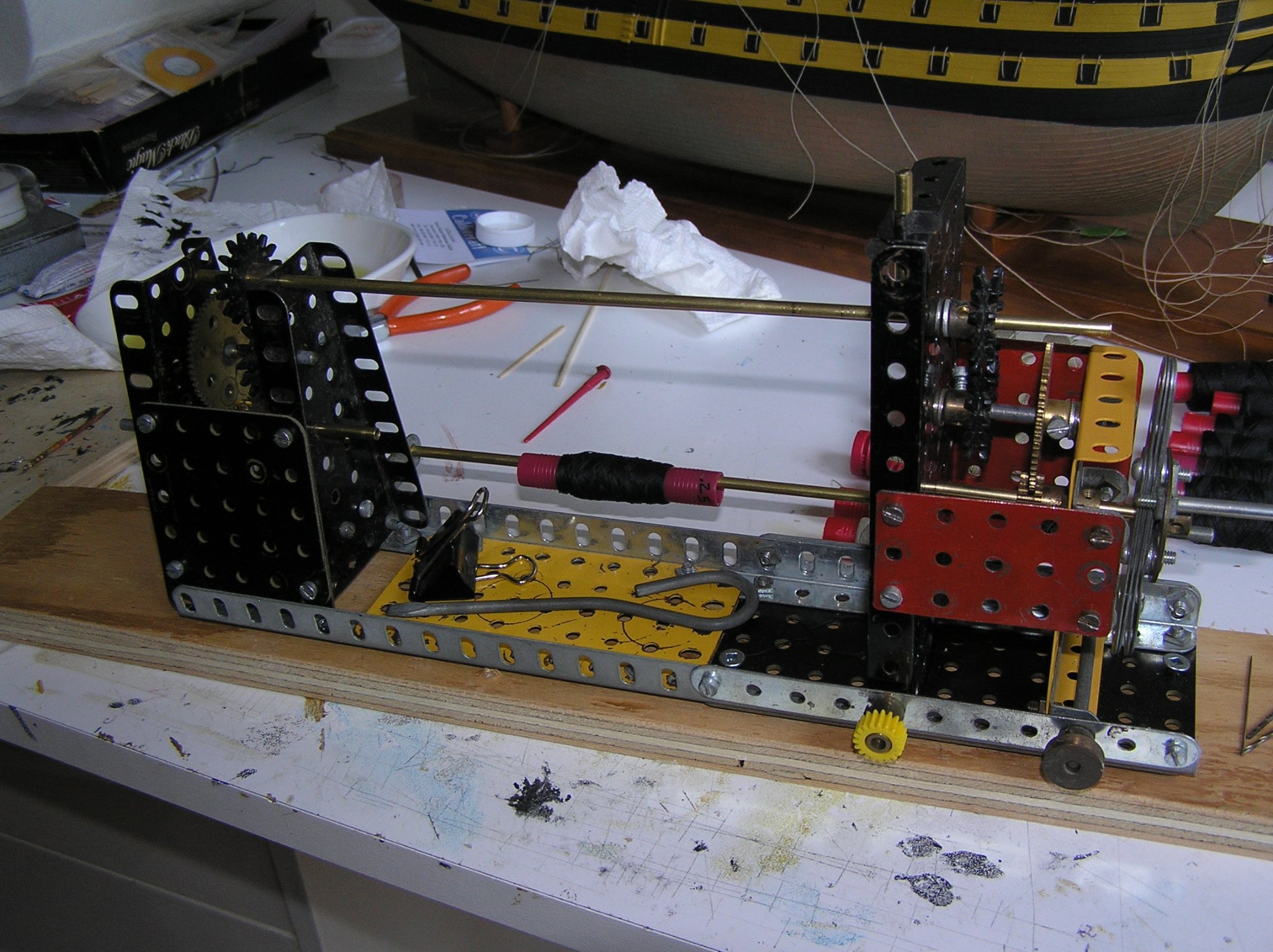
HAHA!! I thought about buying one, but found that I had enough gears on hand to duplicate the ratio in both towers so.... The two wheels on short axles at the bottom are "pins" to allow me to move the right hand tower toadjust the distance between the two towers. Built that feature in but never used it. The two hollow shafts are brass tube at meccano diameter. It's screwed to the board to allow me to clamp it near the edge of a bench. Making a meccano ropewalk would be cool! Ian
-
Welcome; but I thought Uhtred Ragnarsson torched Grimsby??? 😄 (I'm in the midst of reading the series, again)
-
Viking ship rigging ... What’s this called
Ian_Grant replied to Srodbro's topic in Masting, rigging and sails
Don't know what they're called, but I have some modern metal ones (much smaller scale) bought in outdoor supply store. I use them to tension the guy ropes on the pool's leaf net cover every fall, then remove the net after the leaves are down and before snow. -
A few years ago we were on holiday, driving along the shore of the Bodensee in Germany, when we saw a sign advertising the "Zeppelin Museum" ahead in Friedrichshafen. I said "We need to stop and see that!". It was very interesting and all of us including the kids enjoyed it. Highly recommend.
-
Veszett - great pictures! That steamer really did a number on her bowsprit and foremast....what a shame that whole incident was. I notice also in the 3rd photo that the upper part of the boiler hut walls are the same colour as the roof; I might change that before adding the forward catwalk. I found some K&S thin-wall tubing that should just fit over the catwalk support posts. If my local shop has in stock I will buy today. I figure I can cut some consistent short lengths and put them over the post ends, adjusting to get the correct length. I'll pad the bottoms of the boat beams as required. Won't quite be trivial as I recall from the fitting the 3D-printed ladders that the bulkheads are not all the same height. Again, in these picture the mast stays are seized together. Thank you for the photos! Ian
-
Veszett and Cirdan, thanks for your replies. I would think that the catwalks would be level, too. It's just that Heller has made the support posts too short. If I extend them to raise the catwalk, I will also need to raise the boat beams since they support the catwalk too. Doesn't sound trivial, I will have to think about it. It's the same story for the forward catwalk; if I raise it I will have to pad the lower walls of the boiler hut. Looking at the pictures Veszett sent in post #43, they look much cleaner when level. I also notice this model has support posts in pairs whereas Heller has triangular flanges under the walks, with single posts. But at this point I will not change them. Will think about it. Regards, Ian
-
Thank you Wayne! And thanks for your interest.....yes it was always going to be revisited but I was distracted for a while. Any start date estimate for your Passat?
-
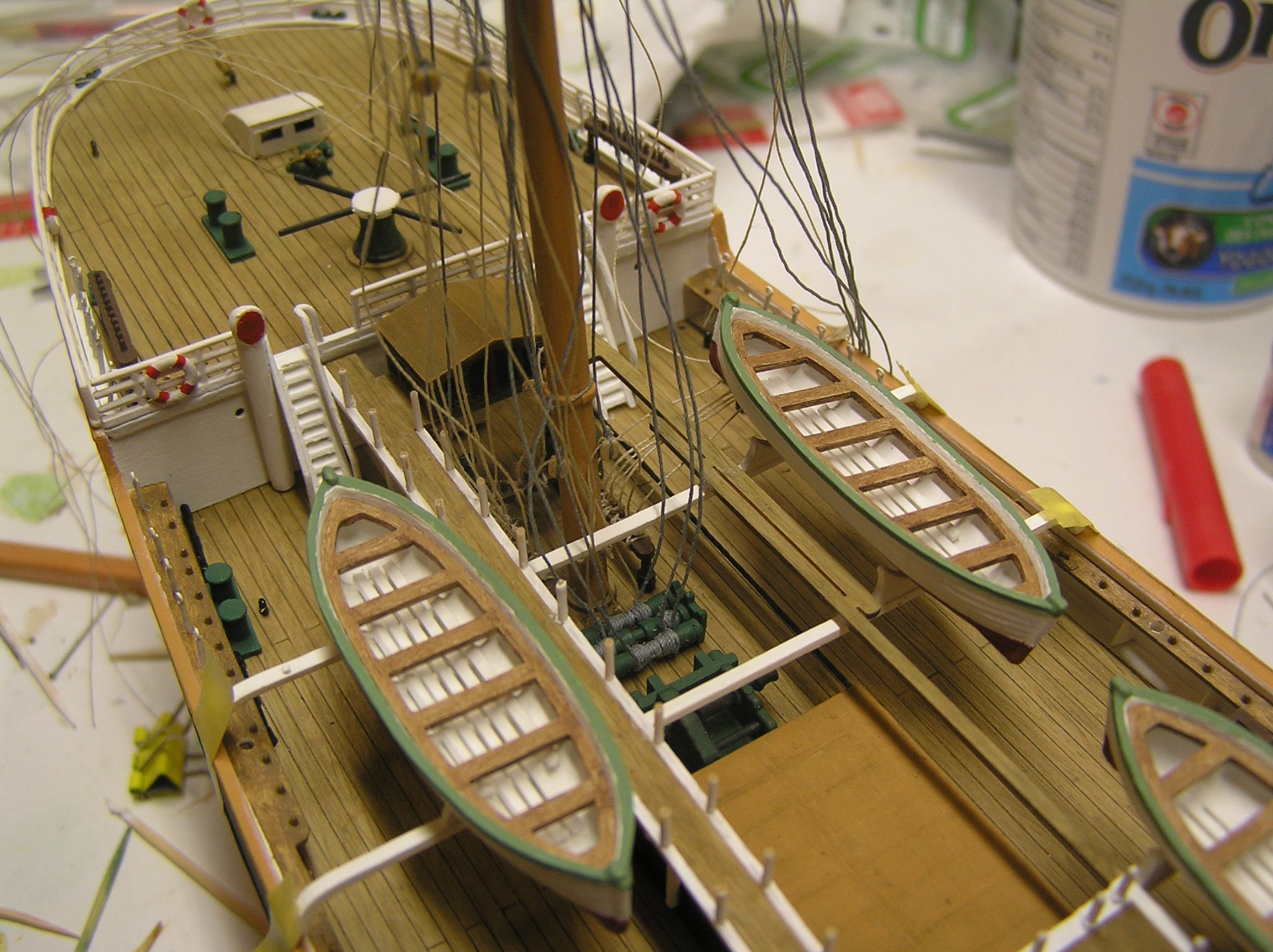
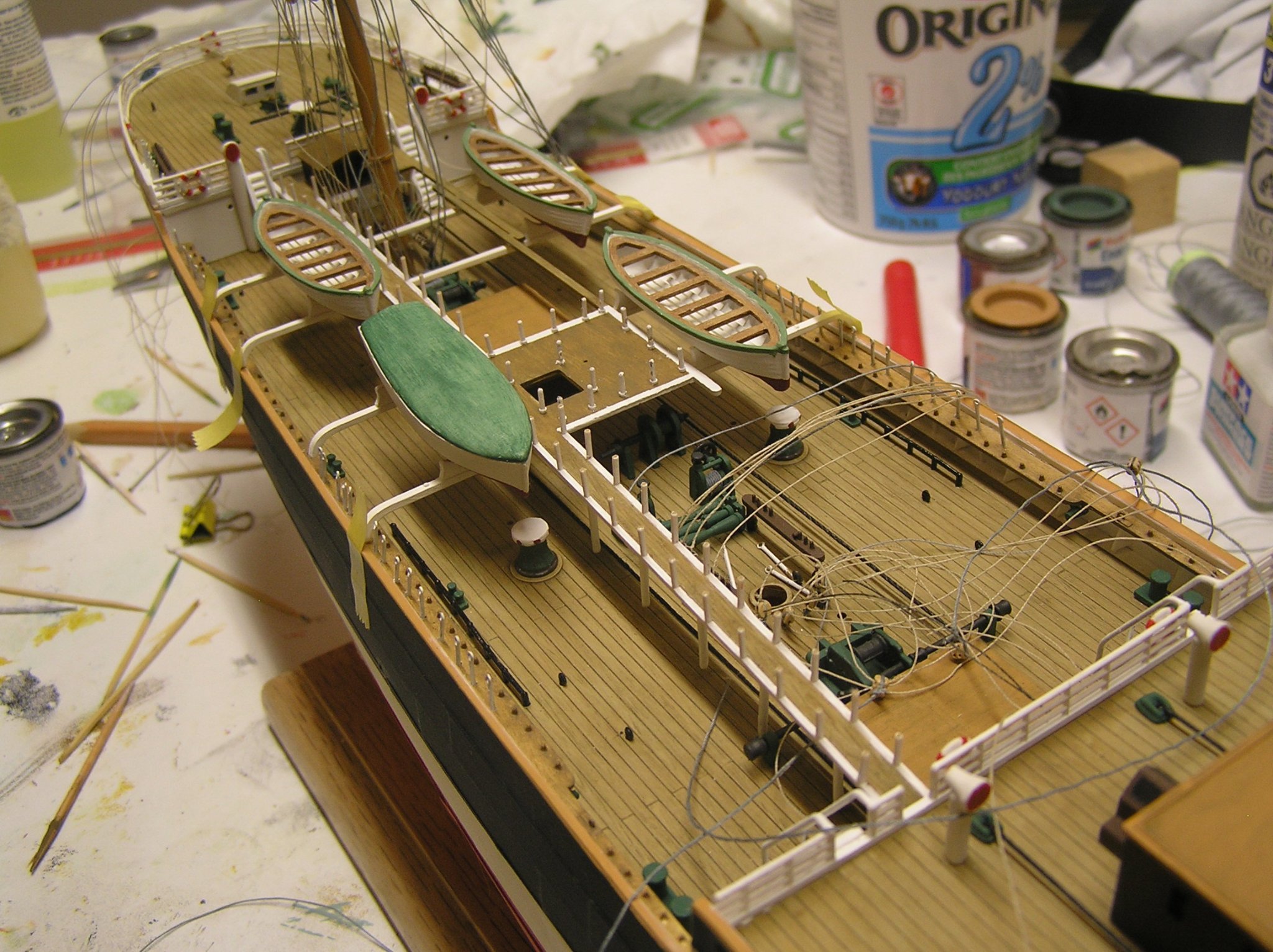
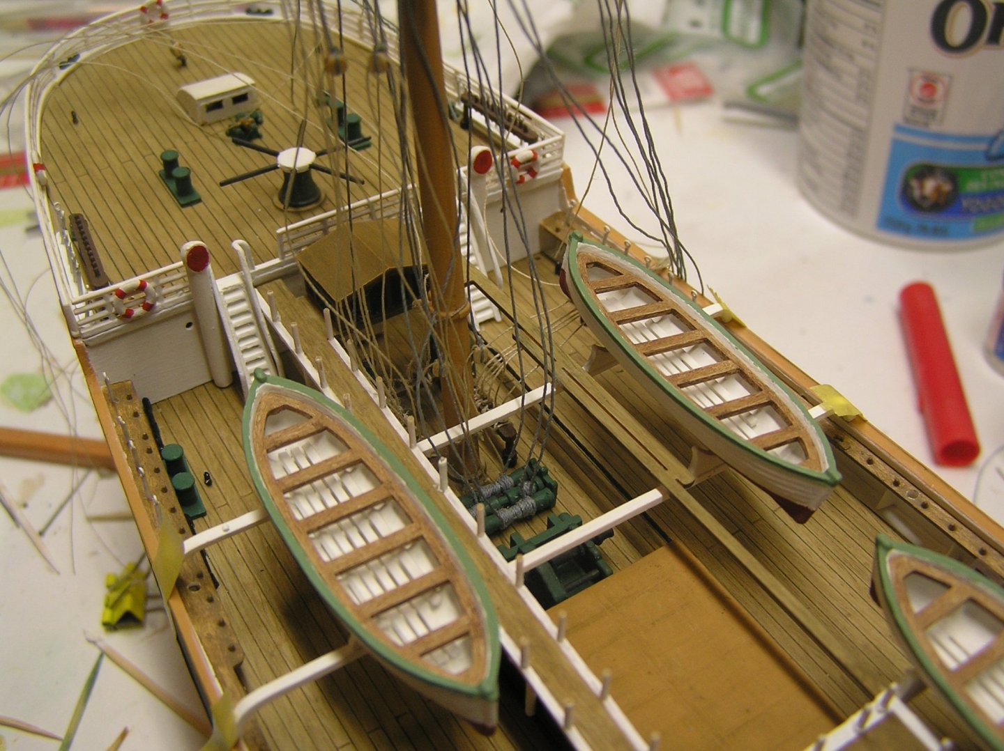
I rigged and glued in the two halyard winches aft of the mizzen since they are pretty close to being under the flying bridge on the catwalk. The catwalk was then passed down the jigger mast, twisting and turning to dodge the crosstrees and the top. The catwalk is not glued to the deck; the boat beams are not glued to the bulwarks; the boats are not glued to the chocks. I just placed it all temporarily to see how it looks. I'm still trying to figure out an assembly sequence for all these pieces. Each boat beam has two posts to the deck for support. There are holes in the deck, but no indication on the underside of the beams as to where the posts meet them; more Heller butt joins. There are no indications on the bulwarks as to where the beams meet them; more butt joins. So one must place the boat beams vertically over the holes in the deck, either gluing to posts already in deck and hopefully vertical; or gluing the posts in after. Hmmm🤪 Here are a couple of photos. You can clearly see (or clearly not see?) the jigger bitts are near invisible now as far as rigging them after is concerned. Hence the reverse-rigging I talked about. Victor J. had told me the catwalks were not flush with the decks (as somehow I expected) given the height of the support posts. He is right. It is quite a step down from the poop deck, but trying to raise it would screw up the boat beams. Maybe I will add a little step later.

-
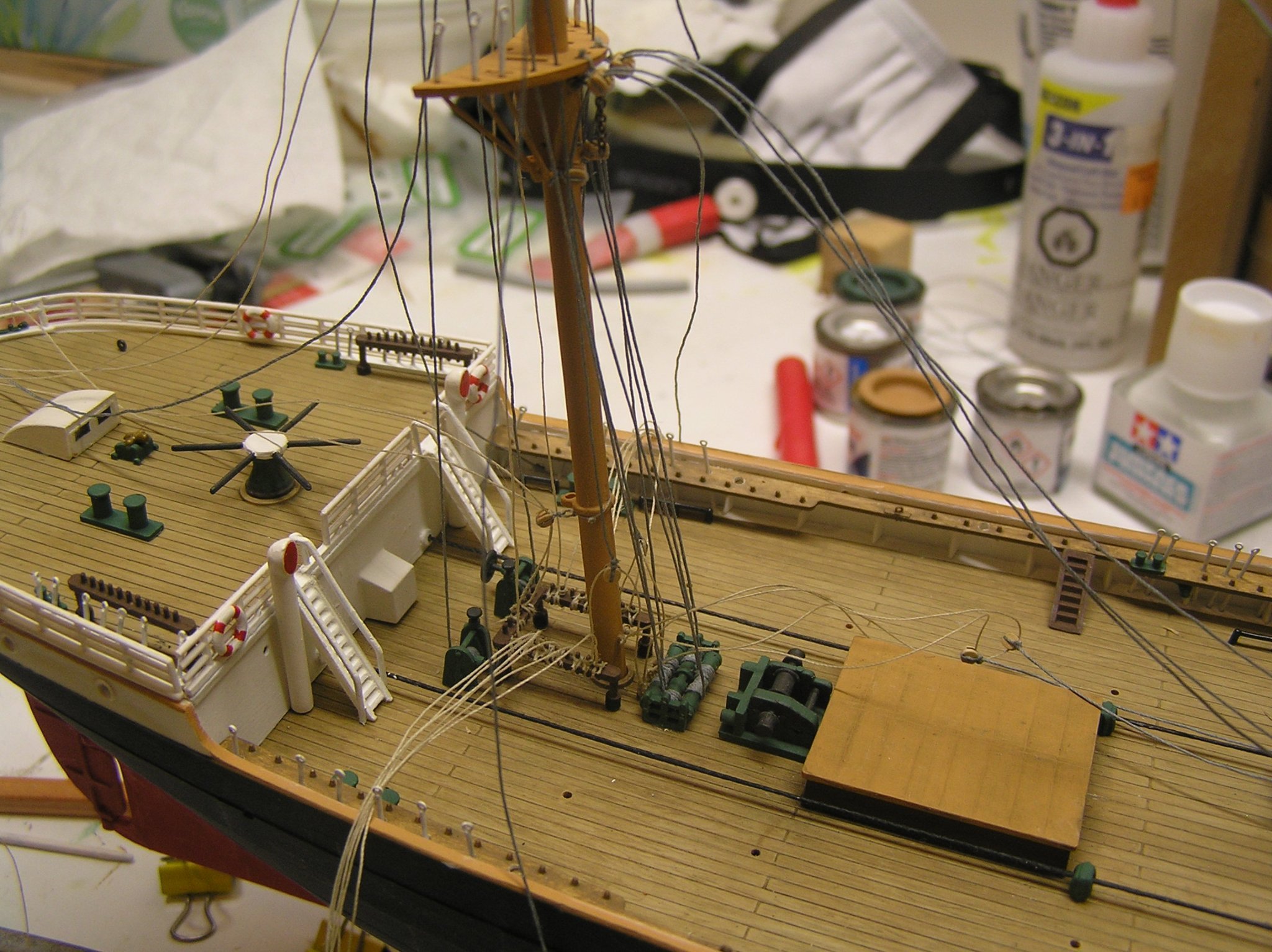
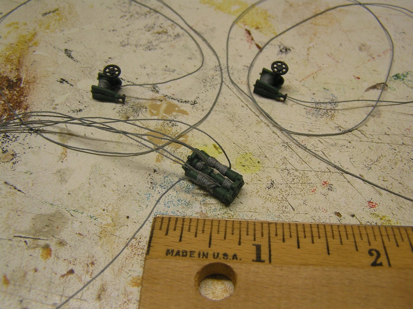
I spent a longer than usual session today...too cold to cycle, no snow to ski on 😢. I rigged a Jarvis brace winch and two halyard winches for near the jigger mast. The brace winch was pretty fiddly, I'm glad there are only four more. I cheated a bit by rigging the two drums which taper toward the middle with one piece of thread each. Few observers of the finished model will notice, I am confident. The halyard winches were pretty easy and that's good because there are eight more. Here's a shot of the rigged winches. Notice six threads emanating from the very small brace winch. I recall saying earlier in this log that I would add crank handles to them; that idea has fallen by the wayside. 🙄 And they are now cemented to the deck. The braces, which are for the mizzenmast, are threaded through their leading blocks on the jigger which keep them away from the jigger lower yard & course. I consulted Underhill for brace routing with these winches, but his very nice diagram shows how they were routed to winches placed aft of the masts while avoiding interference with the courses, not forward as here, so I placed leading blocks where it makes sense to me. There is one winch aft of a mast on Preussen, the mizzen in fact, for the jigger braces which obviously must lead forward. The two halyards from the winches aft of the jigger pass through drilled holes in the mast appropriately located for the upper topsail and upper topgallant yards. Heller's instructions show the two winches facing opposite ways; not sure why. The royal halyard is a manual affair as are all the other royals. The two small tangles with blocks lying forward of the jigger are the whips for the jigger lower topsail sheets, which tie off to cleats at the base of the mast. I think I'm ready to add the storm catwalk.

-
Proceeding with rigging. Plan is to glue in masts one at a time, from aft to forward, so I can attach the lower and topmast stays at the foot of the next mast forward before it's in the way. Also plan to rig in reverse all the lines that terminate at mast bitts - I'm not good at reaching right in to tie stuff. When the after storm catwalk goes in, the feet of the mizzen and especially the jigger mast will be near-inaccessible. Another reason to rig a lot of things in reverse. Here's a pic of some jigger and mizzen rigging lying all over the after well deck. Quite a mess. Only the jigger is cemented as yet; you can see the chain sling awaiting the jigger lower yard. I can run all these lines up the masts and tidy up after the catwalk is in, but first some rigged (haven't done yet) halyard and brace winches need to be added to the well deck too. The boat skid beams can then go in. Plan to add most of the fore-and-aft mast stays before getting to shrouds. Fingers crossed.
-
Kind of like where cartoons sometimes show both eyes on the same side of the nose......
-
OOPS! I see I duplicated the first entry, replying to Steven. Oh well, mine has pictures 😄
-
The Real Purpose of Household Tools DRILL PRESS A tall upright machine useful for suddenly snatching flat metal bar stock out of your hands so that it smacks you in the chest and flings your beer across the room, denting your freshly-painted project which you had carefully placed in the corner of the room where nothing could get to it. WIRE WHEEL Cleans paint off bolts and then throws them somewhere under the workbench with the speed of light. Also removes fingerprints and hard-earned calluses from fingers in the time it takes you to say, "Oh ****!". SKIL-SAW A portable cutting tool used to make studs too short. PLIERS Used to round off bolt heads. Sometimes used to create blood-blisters. BELT SANDER An electric sanding tool commonly used to convert minor touch-up jobs into major renovation jobs. HACKSAW One of a family of cutting tools built on the Ouija board principle - it transforms human energy into a crooked, unpredictable motion, and the more you attempt to influence its course the more dismal your future becomes. VISE-GRIPS Generally used after pliers to completely round off bolt heads. If nothing else is available they can also be used to transfer intense welding heat to your hand. OXYACETYLENE TORCH Used almost entirely for lighting various flammable objects in your shop on fire. Also handy for igniting the grease inside the wheel hub out of which you want to remove the bearing race. TABLE SAW A large stationary power tool commonly used to launch wood projectiles to test wall integrity. HYDRAULIC FLOOR JACK Used for lowering an automobile to the ground after you have installed your new brake shoes, trapping the jack handle firmly under your bumper. BAND SAW A large stationary power saw primarily used by most shops to cut good aluminum sheet into smaller pieces that more easily fit into the trash can after you cut on the inside of the line instead of the outside. TWO-TON ENGINE HOIST A tool for testing the maximum tensile strength of everything you forgot to disconnect. PHILIPS SCREWDRIVER Normally used for stabbing the vacuum seals under lids or for opening old-style paper-and-tin oil cans and splashing oil on your shirt; but can also be used, as the name implies, for stripping out philips screw heads. STRAIGHT SCREWDRIVER A tool for opening paint cans. Sometimes used to convert common slotted screws into non-removable screws, or for butchering your palms. PRY BAR A tool used to crumple the metal surrounding that clip or bracket you needed to remove in order to replace a 50 cent part. HOSE CUTTER A tool used to make hoses too short. HAMMER Originally employed as a weapon of war, the hammer nowadays is used as a kind of divining rod to locate the most expensive parts adjacent to the part we are trying to hit. UTILITY KNIFE Used to open and slice through the contents of cardboard cartons delivered to your front door; works particularly well on contents such as seats, vinyl records, liquids in plastic bottles, collector magazines, refund cheques, and rubber or plastic parts. SON OF A BITCH TOOL Any handy tool that you grab and throw across the garage while yelling "Son Of A BItch" at the top of your lungs. It is also, most often, the next tool that you will need.

-
She certainly is "bluff of bow" isn't she? I really like the stand! 😁 Good work Bro!
-
God, I hope they didn't need to traverse that in order to bail out if necessary! Thought the too-small escape hatch in a Lancaster was bad....!
-
More impressive each week! Will you remove the upper works to plane & sand the B&B lower hull, or just flip the whole monster over?
- 454 replies
-
- 2
-

-
- Union Steamship Company
- Stepcraft 840
- (and 3 more)
-
Sorry about that Kevin. The Victory is a big task for first build. I'm glad mine sat in the stash for years as I was able to find help on the Web when eventually I pulled it out. To be perfectly candid, this site makes it very easy to say, "Oh, I'll do that too", to get the very best model. But a lot of the little details I did on Victory I did with magnifying lenses on, which means one would need the same to see them. With it sitting in the case you can hardly see the main deck guns, much less their train tackles. All this to say, you don't need to go as far as some of the builders here to get a very nice model out of it. I'm not going to sweat the Preussen near as much; in fact I've decided to omit the footropes on her 30 yards 😜 and I'm just adding etched eyebolts instead of blocks in some places. Good enough. No one in my probable audience will know the difference anyway.
-
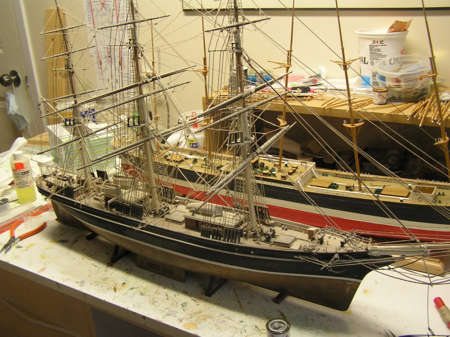
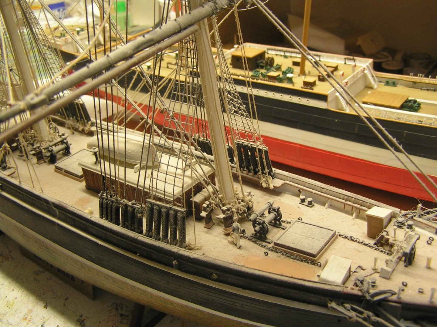
Agree with Bill about the Revell 1/100 models. They come with detailed rigging instructions which are a pleasure to follow. Bill, looking again at your Cutty Sark I see the taut shrouds/ratlines look like hard plastic. Is that what they are? Back in the 70's the Cutty Sark came with pre-formed shrouds/ratlines which were sort of thread-like, very pliable, and too thin really. And hard to get uniformly taut at least for my teenage hands. Here are a couple of pictures of my horribly dusty model, which has been sitting out of public view in the shipyard for years but is not unloved. I wiped a portion of the deck with my finger to show how filthy she is.😢 I really should clean and repair her; some of those shrouds have snapped and a few bits have come loose, but then where to put her? On the other hand I plan to find a place to put Preussen (with the Admiral's approval).....
-
Nice! Makes me think about cleaning the decades of dust off mine 😃. And fixing the broken bits.
-
Actually the old SR instructions are much better than were those for the Victory, to be devil's advocate for Heller. The rigging is mostly shown in a few diagrams at the end instead of being scattered throughout as a bunch of loose ends disappearing off page. In fact, that mainmast diagram in your first pic is given on pg 23 of the old instructions, although not in colour and showing only the port side since it's symmetrical. A similar diagram of the stern statuary is on pg 17, again not in colour, as well as a beautiful rendering of the fully assembled stern on pg 16. Having said that, who knows about their accuracy? I can tell you that those for the Preussen have errors. As always, reference books are de rigueur.
-
Maybe they finally wrote some decent rigging instructions. Other than that Bill I don't think you'd get much out of it at the stage you're at. Use Longridge to rig her. So you opened something in your wife's "secret" stash? How will that turn out? The SR is a helluva kit. Many problems with Heller's hull, cannons, and spars, but the engraving and molding is first class for the time. I haven't started mine yet but from time to time I open it up to look at it 🙄. I've dry fitted the stern and quarter galleries and they're amazingly accurately molded. By the way I recommend R.C. Anderson's book for rigging SR.
-
That was me. I needed a replacement stern railing for my "Preussen". When I emailed the form, the message bounced and I received a complicated "server refused access from my domain" message. That's why I faxed and got an immediate response (I'm lucky that my wife is a vet; in Canada the medical community is the last segment clinging to FAX machines for some reason). BIll if you didn't get a bounce message then the email was received. Bottom line it looks like they don't take direct orders. You might be better to order from someone more local.