


Modeler12
-
Posts
1,716 -
Joined
-
Last visited
Content Type
Profiles
Forums
Gallery
Events
Posts posted by Modeler12
-
-
That's exactly what I was referring too, also. It's not just the thickness of one line. Your trying to draw four items through, the line doubled and two sides of whatever your using to draw. The hole in the block now has to be three or four times larger than it should be.
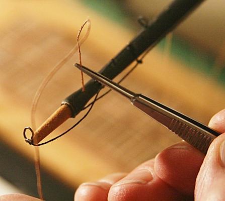
Seems to me like your better off hardening the line with a drop of CA
Kind of like I showed above, Henry! The hole in the spar is not too visible, but it is there.
-
You can buy these things for pennies at any department store Walmart, Target, etc) These are used by people with dental braces to pass dental floss through them. Long flexible stem, really wide eye and super resistant. I bought a bunch of these about 6-7 years ago and still have plenty.
Good, but when you pull the string, dental floss or whatever you want to use this way, you still have to pull two parts of the line through the round hole.
The threaders used by seamstresses are fine for them because the hole in the needle is elongated and not round like in our blocks, sheaves, etc.
I like the idea, though, of using various dental gear. This is another one. I have been trying to get hold of a few small rubber bands like used in braces, but could only find them in batches of 100 for too much money. Of course, we all use tooth picks.

-
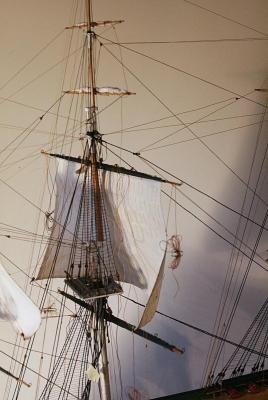
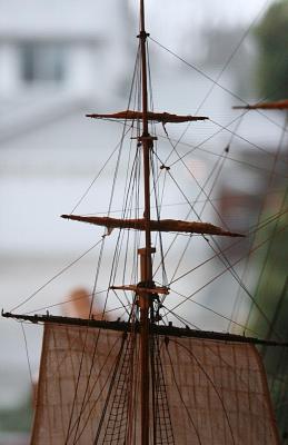
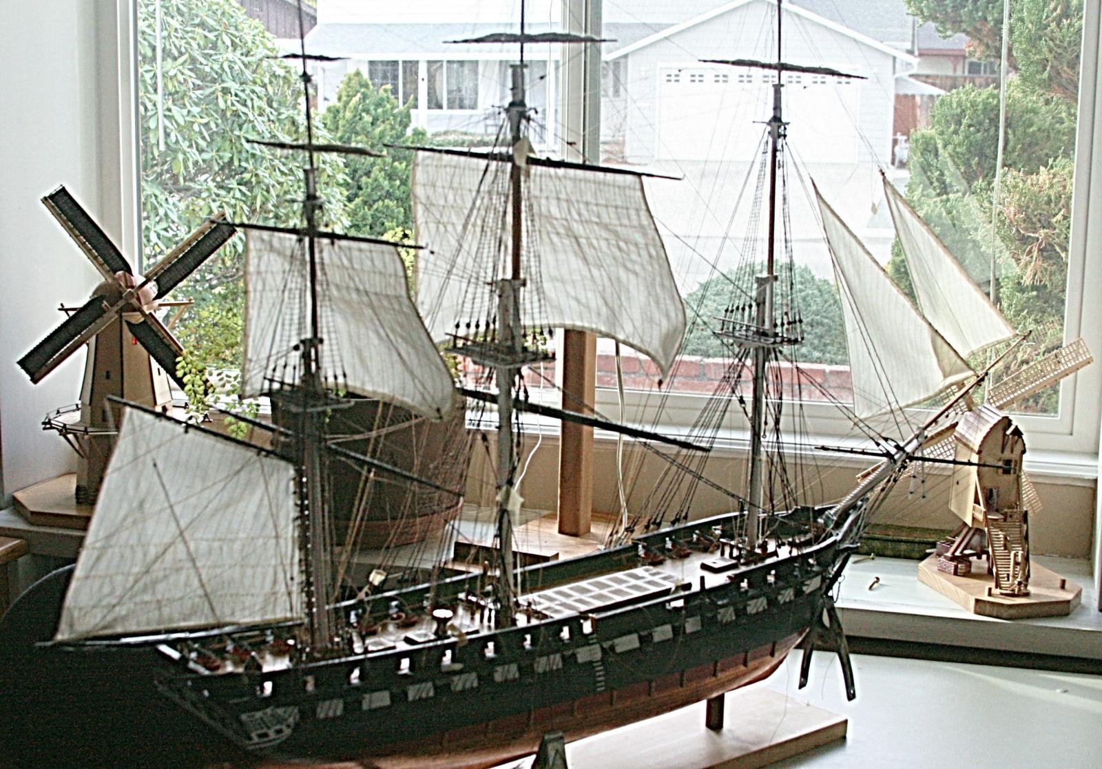
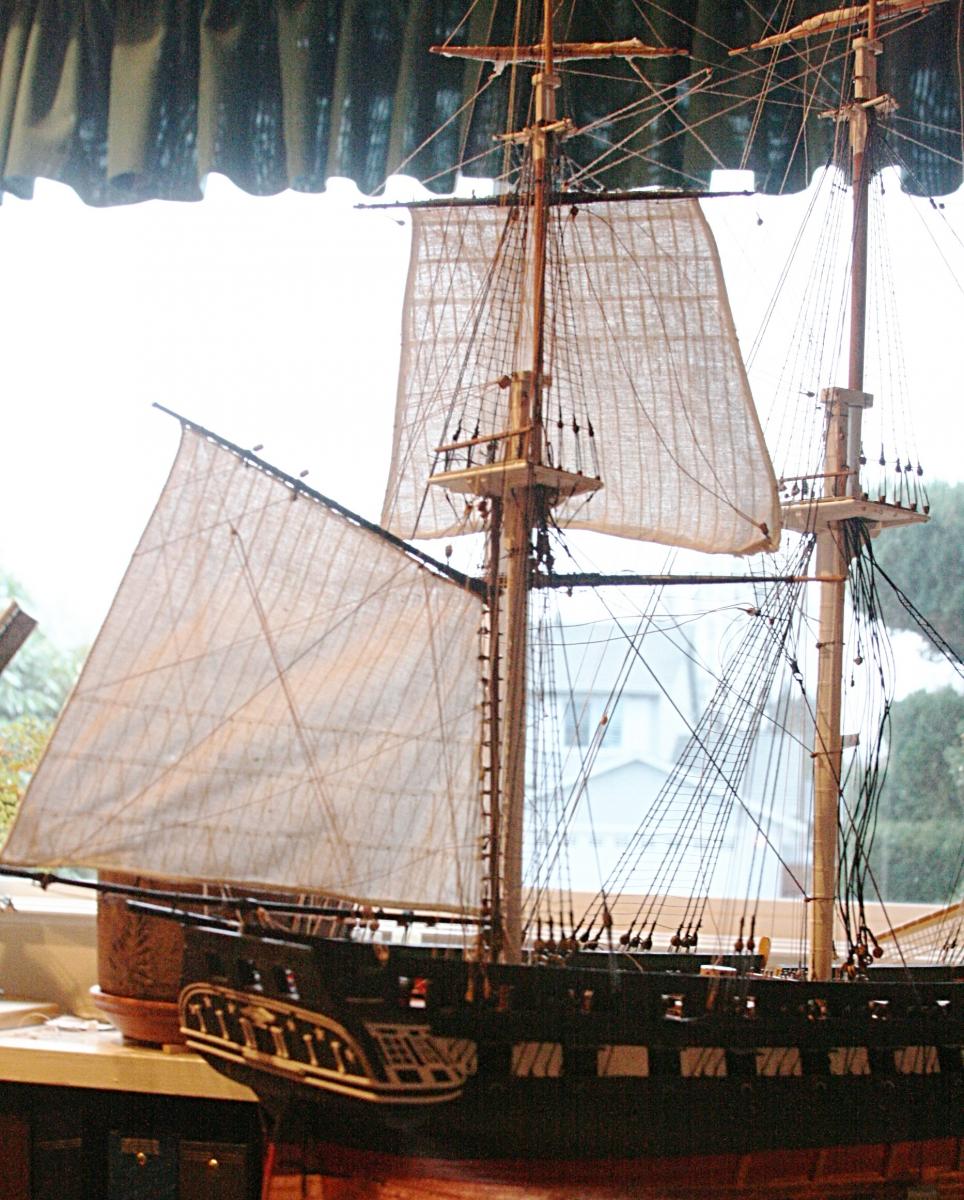
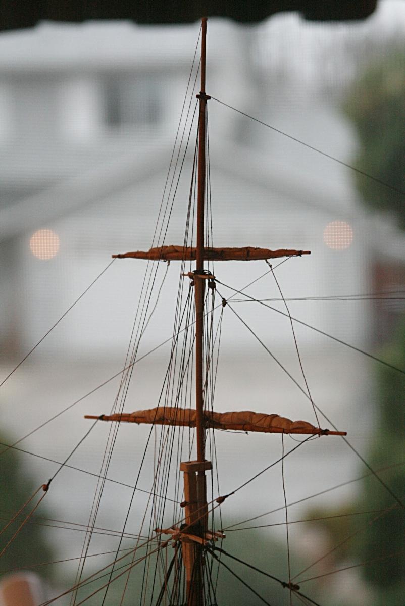
Here is one more picture showing the five out of the six sails she will carry.
Today was slow going. Needed to do some 'chores'.
But I am constantly finding more eyebolts and blocks I need to add. But then I also have some eyebolts on deck and on the masts that I don't know what they are for.

Better more than not enough???
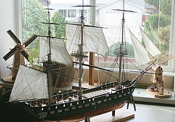
BTW the neighbors across the street are really nice people but I am not promoting their house, even if it were for sale. Termites, you know?
I even found one in my sails. But that was another story here on this forum that turned not to my liking. Besides the SF Bay Area also has earthquakes, strange people and sky-high prices. Don't come to live here, please!Sorry I added some windmills in the picture above. There is one on either side. They happen to be of the same scale as my Connie. The small one to the right is similar to what my ancestors used to grind wheat in Holland.
- CaptMorgan, Blue Ensign, WackoWolf and 2 others
-
 5
5
-
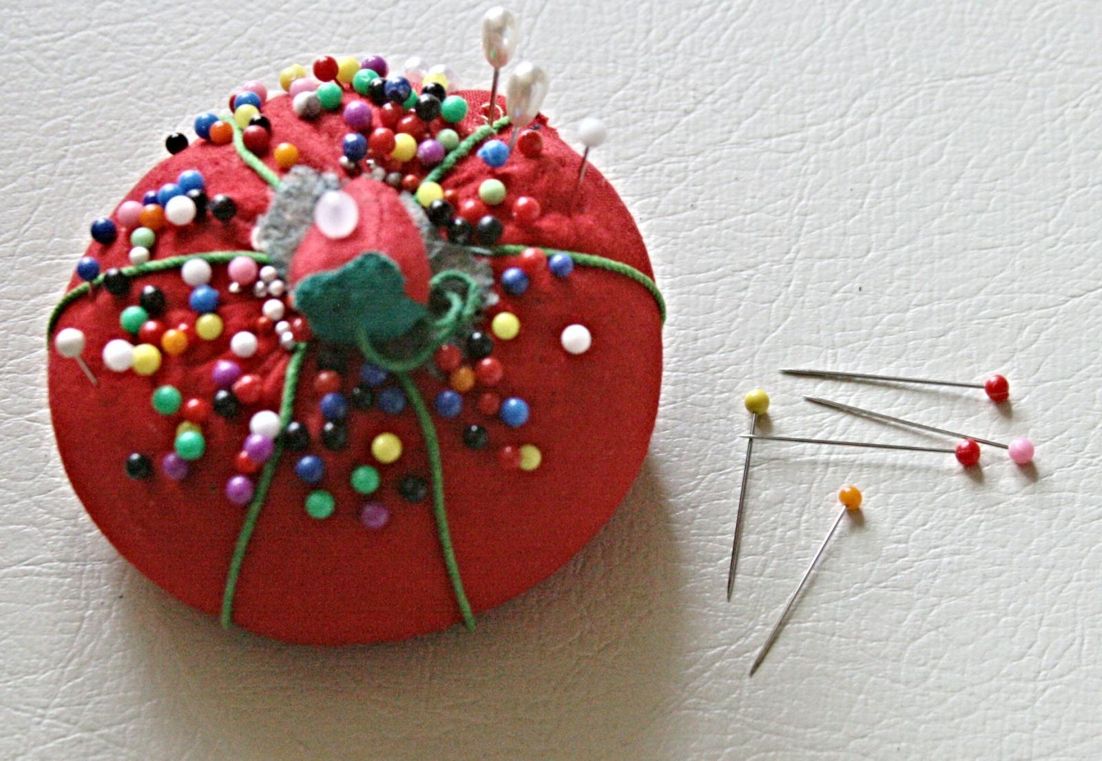
Ah, Gary, now I recognize the pins. They are the 'old fashioned' type rather than what my wife has in her sewing box.


I am enjoying your fantastic build and will have to absorb a lot for my Pelican, my next project.
-
The problem with this kind of approach is that the hole has to be big enough for two lines to go through.
Some of the blocks I am using just don't have enough space to drill the holes that big.
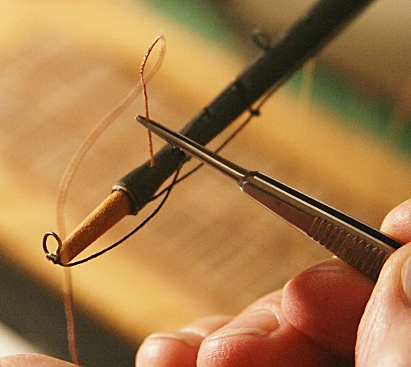
I simply smear a drop of CA glue to the end of the line (about 3/8 inch is enough) and trim the tip to a sharp point.
My threaders from Joann's are in a drawer somewhere. -
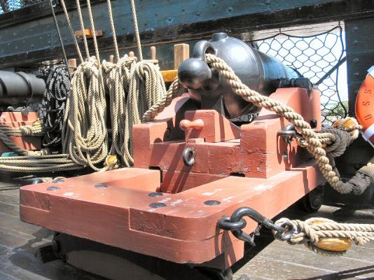
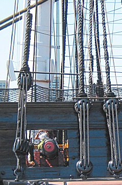
My first impression was that the breech rope is too long. The recoil would be tremendous and the cannon could end up past the tackle that hauls the cannon midshipwards.
Then I noticed also that the breech rope goes under the tackle in one picture, as pointed out by others.
And third I agree that the breech rope goes through the ring the wrong way. The sudden jolt of the cannon would draw the rope tight from the back forward and flip the ring the wrong way.
In fact, there should not be a ring in the first place.
Here is a picture of what it looks like on the USS Constitution.
-
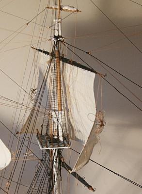
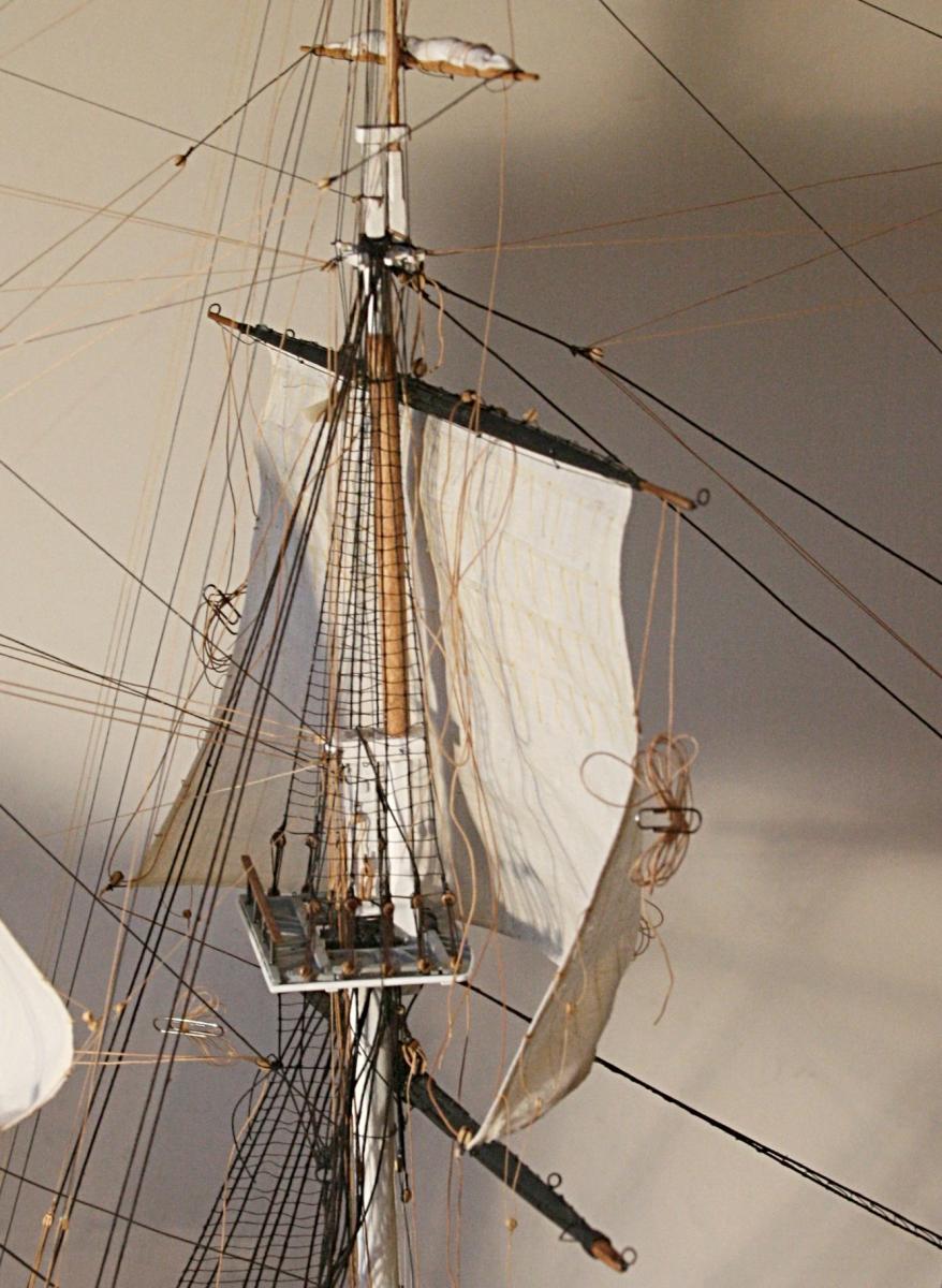
There is still a lot of rigging to be done on the main topsail. I also have to make final adjustments to the sheets and bowlines. Notice the main jack is still hanging loose and not in its final position.
I even may have to 'fill' the sails some more.But I will wait with that until the fore topsail is in place. It's going smoother, that's for sure.

- capnharv2, bhermann, CaptainSteve and 1 other
-
4
-
I see what you are referring to. The second and fourth pictures make it clear.
That way it was easier to manage the bucklers from the inside, rather than from the outside. Sealing would still have been more of a problem, I suppose.
Your build looks awesome. Keep up the great work.
I am curious what you are doing with all those pins. I will have to take a closer look at your log.
-
Thank you guys for your nice comments.
Here is one of those 'I should have done . . .'.
Just when I am ready to start threading the various lines for the topsail, I realized that I 'forgot' to add the blocks to the main jack for the sheets. There are a lot of blocks on the main jack, but I thought they were all for the course sail and not needed. Now I have to add them while the jack is in place.
What I will do in the future is to make a careful study of all the blocks and fitting needed for every spar and mast detail. I keep running into this the whole time since I started the rigging. It is always an eyebolt here and another block there. It is much easier to install those on the workbench and before you need them. I know we are all aware of this, but it gets me every time.
The plans for the Shipways kit are very good and mostly complete, but they do not have a complete listing of what I mentioned here. The fittings for the bowlines is one example. You have to hunt around to find how and where they are attached to the masts or bow sprit.
Re: the order of things: Foot ropes should be the last thing to go onto the spars, just before they are installed on the masts. Mine have been crumpled and been in the way when installing other fittings and furling sails.
-
Amen to that one, Harvey. I had the same problem with one of the fife rails early in the game. I ended up drilling a hole in the bottom of the post (it came out completely) and the same in the deck. Some epoxy is now holding the thing in place. I wished I had done the same with all the others.One thing that I've found over the course of a few models is to make sure the pin rails and fif rails are well attached. I can't count the number of times I've put a little tension on a line going to a pin rail or fife rail and have the whole thing come off-with about 6-8 other lines I had already belayed
 .
.Harvey
SOS, I find that taking pictures as I go along helps me to remember where I was before. Kidding in a way, but I do refer to some of them as I go along. The fact that they might be of interest to others is gravy to me.
Thanks and keep on sailing, my friend. I used to have a junior folkboat in the San Francisco Bay a few years ago and we have many stories to tell about that. Ask my wife.
-
Gary, I am still curious about the inside boards. You mention a picture. I missed that and I am curious about seeing how that works. My next model might have some of these features.Hi Hollowneck. Hawse Bucklers were board's that was put over the holes on the inside and was wedge in place with pieces of wood fitted in holes in the breast hooks, in Alfred time of 1780. They had two types, one was fitted for sea and the other had a hole in it for when they were at anchor. Here's a photo of Alfred's bucklers, one is solid and the other has a hole in it. They are made of two wooden boards each fitted with a rabbet on the edge so they could be fitted and made water tight. Hum can't seem to find any photo's of this. Give me a little bit and will add some photo's. Hope this helps. Gary
-
Pat, I am sure those dimensions varied all over the map depending on the ship we are talking about.
Details???
-
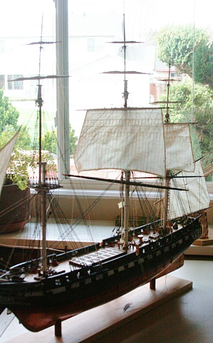
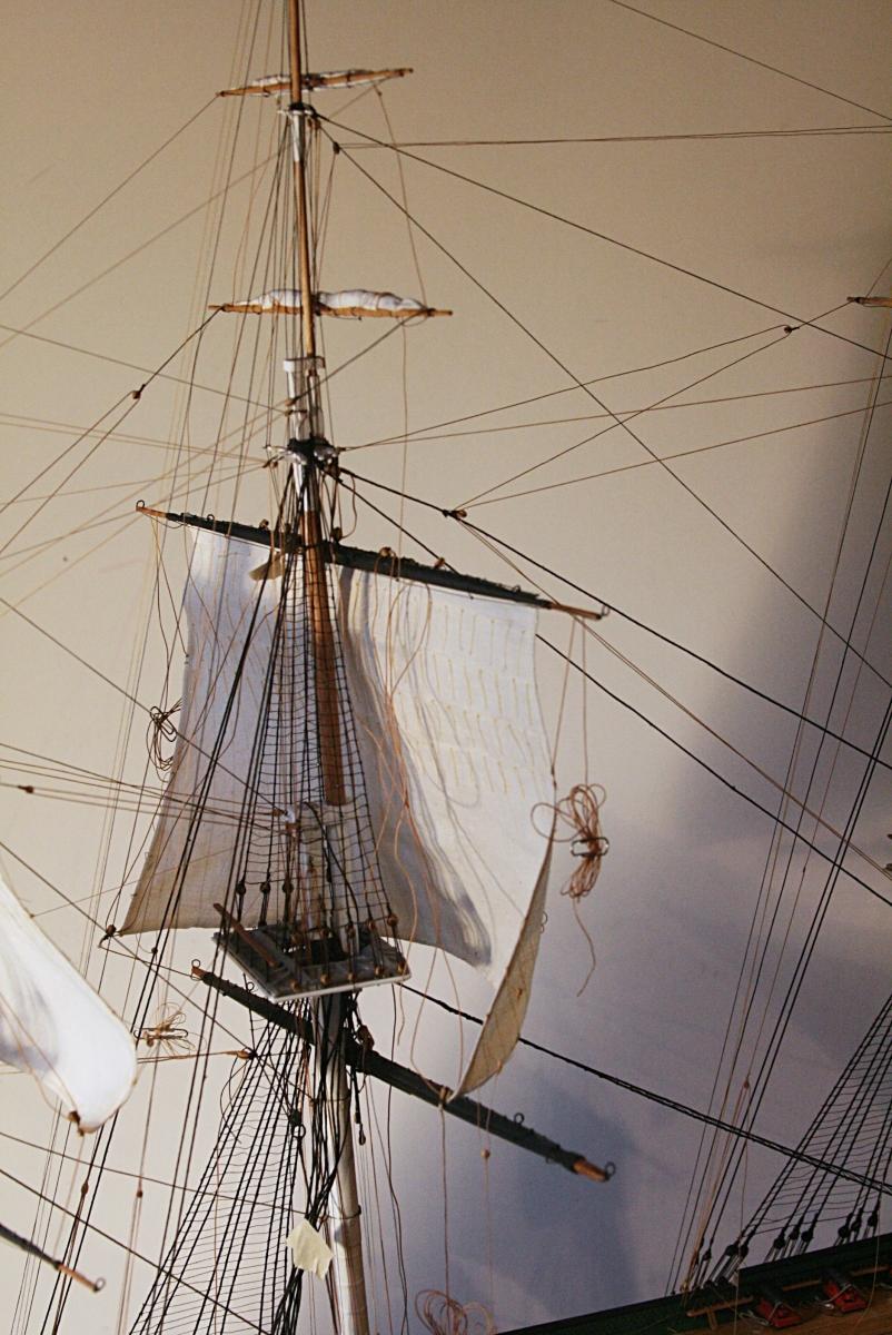
The main topsail has landed!
This was a bit tricky since there are two halliards, one on each side. The first part is looped around the topmast, comes down to the double block on the spar, goes back up to a block on the crosstree and then finally down to the deck. A bit of juggling.
I did this to hold the whole works in place for now. Next comes taking care of all those 'extra lines'.
But now I need a glass of sauvignon blanc to cool my nerves.
- usedtosail, CaptMorgan, dafi and 6 others
-
9
-
Thanks Harvey,Jay,
It's scary, but I actually think I know what you're talking about

A really great job on the rigging. It looks great, and your explanations of why you've done things a certain way make a lot of sense. Thanks for your build log.
Harvey
The further I get into this thing the more I think I may have gone a bit overboard with my unusual approach. For example, holding off with doing the lower shrouds now seems a bit drastic. My original thought was to hold of so I could get to the fife rails to belay the lines. Now I find that at least the ones around the masts are not all that difficult to reach. Those along the rail are touchy no matter what.
Yet, when I think about what might have happened if I had installed the netting on top of the rails . . . . disasters!!!!
The same applies to a lot of other details such as the lower cannons, port hole covers, etc.
I may later put a list together about what order I would (will) do my next build. On hind sight there are a lot of 'if I had done . . .'
-
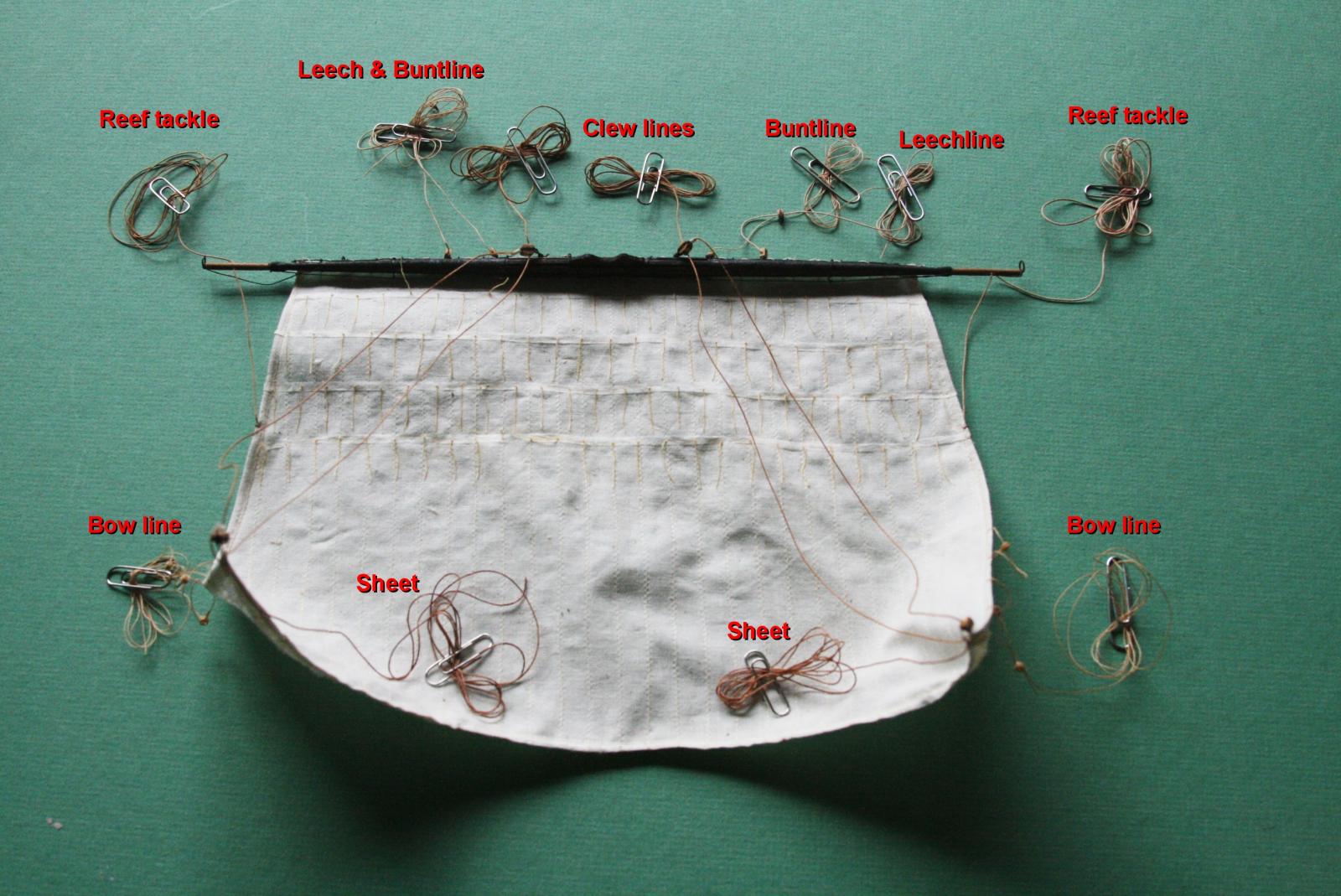
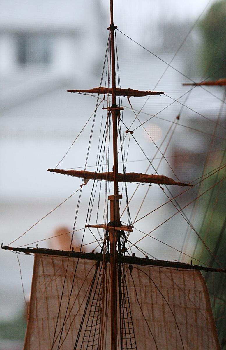
It has been a while and I need a refresher course about sail lines.
Here is the main topsail with all the running lines attached. They all have a port and starboard mate.
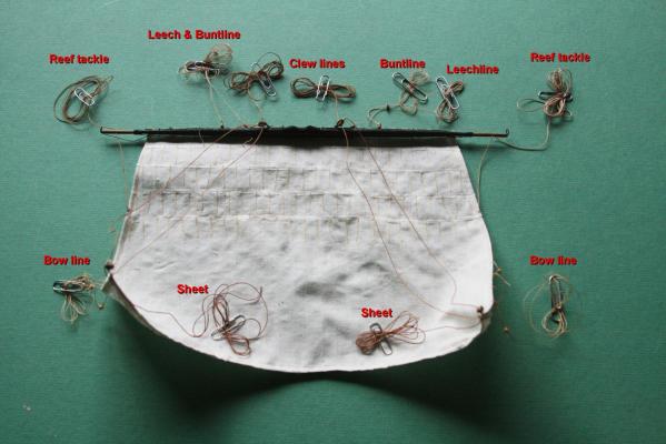
The leech and buntlines go through a small double block and that is why I show them together in one spot. You can see the small block on the right side. All of these lines, except the clewlines, go through a block that is attached to the topmast crosstree. I still have to install those. From there they go down to the deck in front of the sail.
The clewline goes through a block that is lashed to the spar (as shown) and goes down to the deck from there in the back of the sail. The bowlines go up forward to the foremast, and the sheets go down to a sheave in the main jack below.
Confused? I am glad I have the drawings handy.
- dafi, CaptainSteve, bhermann and 4 others
-
7
-
Here is another http://www.youtube.com/watch?v=B_h-PDiLJos
There is no sound and I plan to update this with some details about staining the final rope pieces.
-
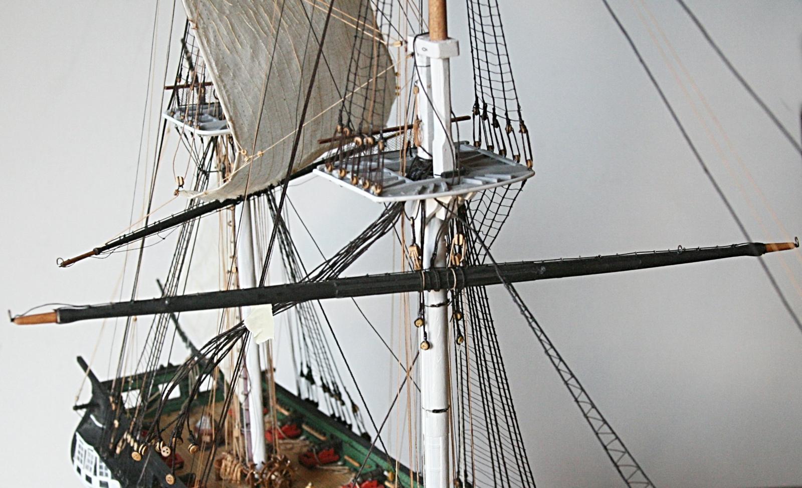
Step two. Putting the main jack on the mast. This was not as difficult as it was with the mizzen.
The jack is rigged but not yet in its final position. The braces will take care of that.

The starboard main shrouds are still swaying in the breeze. Again that is until all those lines coming down from the topsail are belayed.
- dafi, CaptMorgan, trippwj and 1 other
-
4
-
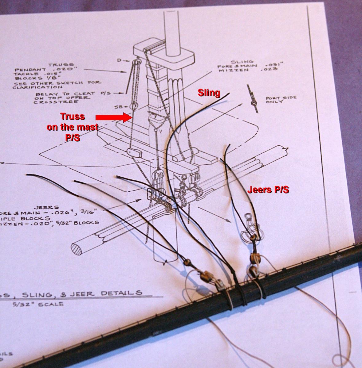
Rigging the main and fore topsails should go a bit smoother, I hope, than the mizzen. I had a terrible time with all those lines coming together at the same place. Then I had trouble adding the parts for the mizzen jack below the sail.
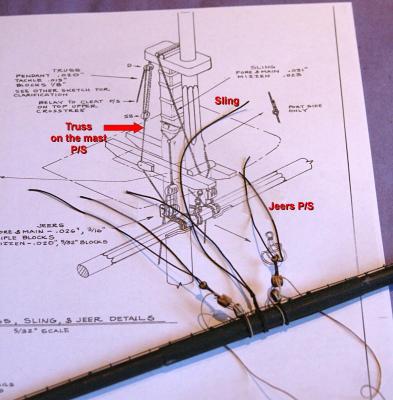
So, now I will take a different approach and rig the main jack first. There are three lines that hold the jack up. They are the jeers (used to raise and lower the spar) and the sling to hold it up there once it is in place. There are two more that are already on the mast. They are port and starboard trusses (P/S) which pull the jack back against the mast.
-
And a couple more. These are for my friend down under who at one point thought I was either brave or crazy to put sails on this spider web of rigging.
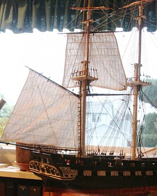

Next comes the topsail for the main. It will be a slow process.
- CaptainSteve, bhermann, dafi and 4 others
-
7
-
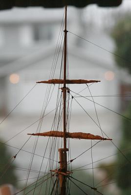
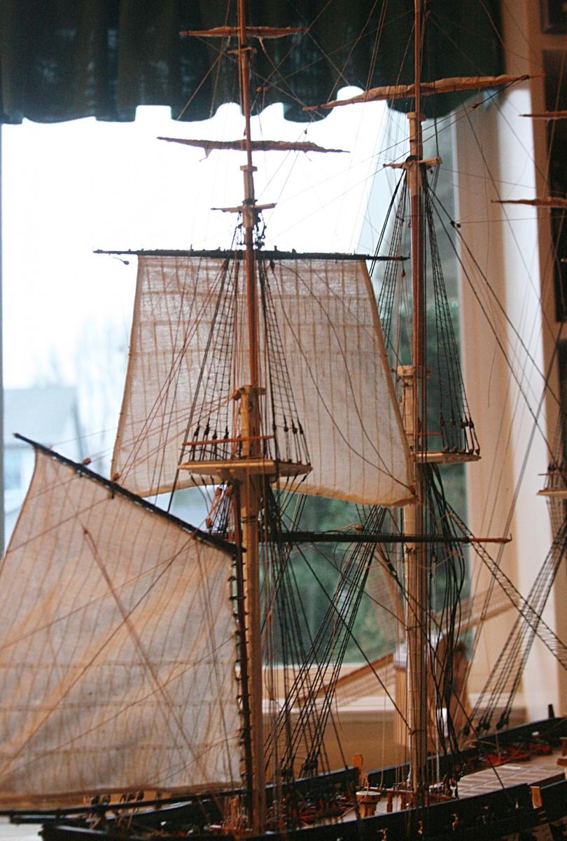
Just a couple more pictures. Mizzen and main.
- dafi, Landlubber Mike, capnharv2 and 2 others
-
5
-
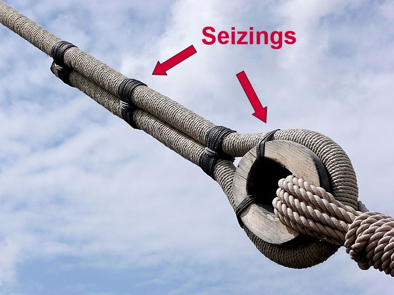
The distinction between whipping and seizing is that whipping is applied to a single rope to prevent unlaying and seizing is joining two items together.
There are several styles of whipping, i.e: plain, palm and needle, sail makers and there are several types of seizings, i.e: cross (or throat), racked, flat and round.
Thanks Henry, I stand corrected. I should have know better.
Harvey, nine inch circumference seems a lot, but if that is for the record, so be it. When I look at photographs I don't see the shrouds to be almost three inches in diameter. Yet on my model the .o40 inch thick shrouds don't seem unreasonably out of proportion.
So, my whole theory goes out the window.
PS There is nothing wrong with 'looking around'. I do it a lot.
-
Harvey, indeed there are six seizings on the shrouds. I took a shortcut and only applied two.
My feeling is that the lines on our models are generally thicker than the real ones, at least at the present, (see your picture). To apply more than a couple seizings with yarn (that also is way too thick) makes the whole look too heavy and bulky.
Here is a little math. I took the picture below and on my computer screen measured the diameter of a deadeye. It was about 0.55 inches. A typical shroud measured 0.125 inches. Now if we assume that a real deadeye is actually about 8 inches, then the scaling results in the actual shroud being about 1.8 inches in diameter. Reasonable I think!
When I divide the 1.8 inches by the scale of our model (76) I get a line thickness of 0.024 inches. The plans call for using 0.040 inches. A big difference, plus the oversized thread for the seizing, and you end up with a pretty heavy look.
Whipping is the process, seizings are the result, I think. It seems that both are used almost interchangeably. I know I have used the picture below a couple times; it came from Wikipedia.

BTW Although I have made and intend to fly an old US flag with 38 stars from the gaff, I am modeling the ship like it is today.
-
Jay,
You've sent me running for my copy of AOTS now.
You might have noticed J 1/2 on pg101, which also demonstrates your point.
(Items 10 & 11, in particular)
Right on Steve.
Again it shows the catharpin without the visual 'interference' of the futtock shrouds. The picture is very clear.
Also notice at the bottom of that page that the main shrouds only have two whippings to hold them to the deadeyes. That is what I used, whereas most likely there were more than that. I still like the drawings in both this book and the one by Petersson's about rigging.
Steve, when you get to this stage, believe me rigging is intriguing.
-
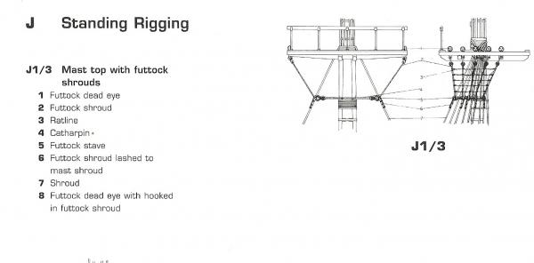
Henry, there is another possibility. The ship did not always have the bentnick shrouds, I am sure. The book by Marquardt 'Anatomy of the Ship . . .USS Constitution' shows a drawing of the futtock area that is much more like most ships of that era. This is part of page 102. Notice item 6.
Of course, I have no idea when the change took place.
- robnbill, CaptainSteve and HIPEXEC
-
3


Hawse Bucklers
in Masting, rigging and sails
Posted
Funny you should say that, Gary. I used the ones I showed above to make door knobs for the windmill I built some time ago.