Modeler12
-
Posts
1,716 -
Joined
-
Last visited
Content Type
Profiles
Forums
Gallery
Events
Everything posted by Modeler12
-
 Indeed Alistaire about the rigging and sails. If I had realized from the start what I was getting into I might have chosen a simpler model for my first crack at building ship models. But I must admit also that I enjoy the various aspects of this whole adventure and I will endure. I had a look at your log for the Fly and you are doing a great job with the hull. The lines look smooth and the planking very uniform. As others have said, the weather is nice and warm (or hot) down under while most of the US is below freezing. I am sure you enjoyed your holidays on the Southern Island again.
- 732 replies
-
- 1
-

-
- constitution
- model shipways
- (and 1 more)
-
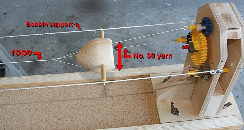
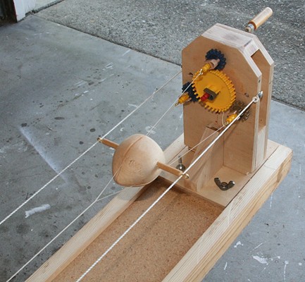
Thanks guys for your comments. Always appreciated. Just in case any of you are interested in the ropewalk, I put together a few clips to show how this contraption works. There is not sound, just some pictures. http://www.youtube.com/watch?v=B_h-PDiLJos Graig, I do appreciate you watching and like your input all the time! S.os You ole salt, you are probably aware that we have a 'real old salt' who is a retired Navy signal person (tittle???) by the name of Popeye2sea (Henry), who served on the USS Constitution. He has been very helpful with taking special pictures for me. Geoff, I can hardly wait for you to get back to real ship building. I miss your great detailed work. One of these days I have to start the 'boats' and you (and others like our friend in Aussieland) will help me then.
- 732 replies
-
- 2
-
-
- constitution
- model shipways
- (and 1 more)
-
Another minor delay in setting the sails. I noticed that I had not yet rigged the topmast back stays for the fore and main masts. Then I remembered that I ran out of rope for this. So back to the ropewalk to make some more. It had been quite a while since I had used it and it took a few tries to make enough for what I need. I bet this is the only ropewalk made with Knex parts. After a few trials I even added a motor on the carriage and rigged my variable speed hand drill to drive the stationary end with the gears. Any way it works. After I have make the rope I will stain it with General Finished Ebony water based stain.


- 732 replies
-
- 5
-
-
- constitution
- model shipways
- (and 1 more)
-
Jud, what you are referring to are the 'standards of the US Survey foot'. Those were kept by a few states in the US because the map coordinates were all based on the old standards and it would be too costly to convert those old maps and survey data. It is not, in my opinion, relevant to making measurements of model ship details. For more details go to: http://en.wikipedia.org/wiki/Foot_(unit)#Survey_foot
-
Just an anecdote: When I was growing up in Holland, my mother would always buy her cloth (yardage) from the tallest sales lady on the open market. Why, I asked. Because she has the longest arms. The cloth was measured in 'el' which is the distance from the tip of the outstretched hand to the shoulder. My mother would end up with a fraction more cloth as long as the price was the same. Actually the el was later defined but varied from town to town. See Wikipedia, if interested.
-
Just for the record, the traditional standards for the exact length of an inch have varied in the past, but now the imperial or US customary inch is defined to be exactly 25.4 mm. To 'convert' that and divide 1 by 25.4 (mm to inch) results only in an approximation. I believe this has been accepted universally. Note that the inch is defined in terms of the metric system and not the other way around. BTW Wayne, the 'standard foot' would then be 12 x 25.4 = 304.8 mm or 0.3048 meters exactly, and not with all those extra numbers at the end. What you were using was, I believe, an old 'standard'.
-
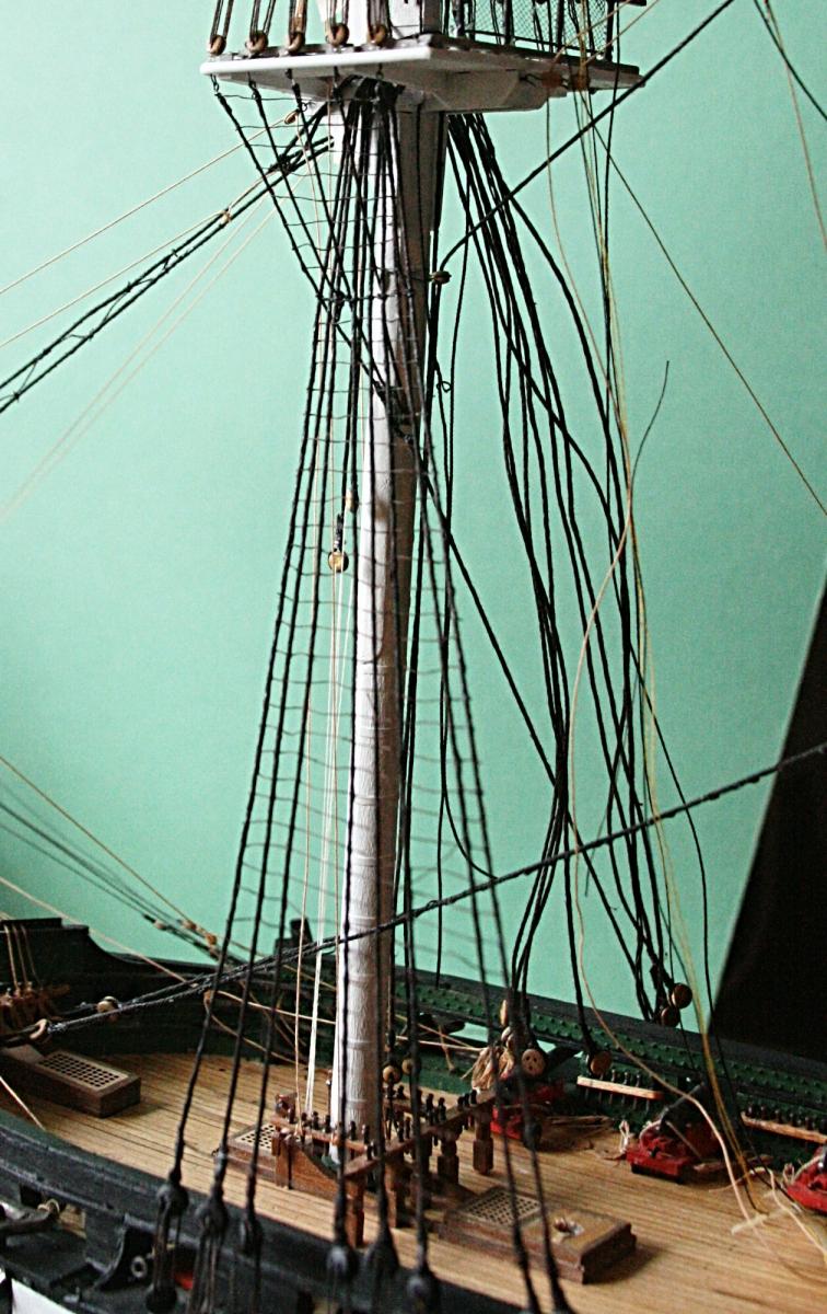
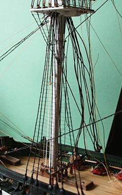
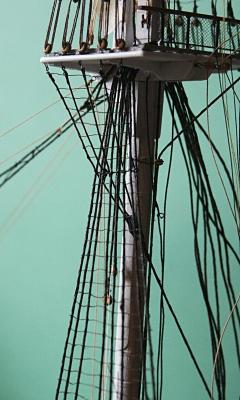
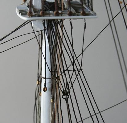
For some reason I cannot get 'Bentnick' out of my mind. This guy, John Bentnick, was a clever officer in the British Navy and apparently invented several useful additions to the ships on which he served. Here is what my thoughts are about his idea about adding this shroud that, otherwise, seems to cross the ship in an unusual fashion. This is a picture of my build, but notice the crossing line Most pictures I have seen show how the upper shrouds (from the topmast) go down to the futtock shrouds, which are then either tied to the main shrouds or go across to the opposite side where they are tied to those main shrouds. What that means is that all the forces imposed on the upper shrouds are transferred to the main shrouds. Assuming that the main shrouds are loaded to the maximum allowable, this extra force is not what is wanted. I can see in reality that the stresses would be more than normal, be it on one side or the other. What Bentnick's shrouds do is to isolate the upper shroud forces (stress-strain, call it what you want) and transfer them to the bottom or main part of the hull. Clever, I think. Later there will be another line coming across from the right to make an 'X'.
- 732 replies
-
- 3
-
-
- constitution
- model shipways
- (and 1 more)
-
Positioning Cathead
Modeler12 replied to robnbill's topic in Building, Framing, Planking and plating a ships hull and deck
I agree with Mark, Bill. A lot of questions you might have will give many answers from a lot of experienced people. At first I was very hesitant to start a log, because I knew that I didn't know a lot. But what the hay; nobody knows everything about one subject, so I asked and still ask and get great information from those who know more than I do. -
Cutty Sark is well known for it's speed and full sails ahead should be nice. But . . To rig all sails correctly takes a lot of time. I am taking the approach to have only topsails, spanker and two jibs full. That way you can still see what is on deck and all those details.
-
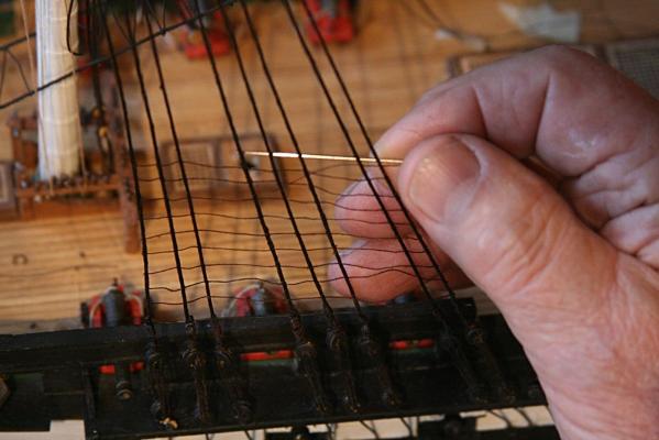
Back to the ratlines. I finished the fore mast rats but did not include the extra staves Henry referred to. They might come later, but already I am getting dizzy with too many lines. Port is my 'bad side' and I hope that the starboard ratlines will come out as bad as shown below. The starboard shrouds are still dangling aft waiting to find a home. I will hold off with those until the topsails are rigged. The reason is that since I decided to have the Connie on a starboard tack and since the sails and spars are pointing in that direction, there is no room on port side but plenty on the starboard side to work the ratlines. Having a clear view and access without the shrouds has been helpful to me. Again my idea of working from the inside out. After this come more ratlines for the main. RATS!!! And then I hope to get back to rigging more sails. BTW if anyone is interested in doing ratlines with thread-and-needle, like I do, here is a suggestion. Thread all ratlines but leave both ends loose. I leave about an inch or two at both ends. Periodically I snug up on those ends to see if all is going ok. The thread should go through the shrouds nicely for adjustments. BUT I DON'T GLUE THEM IN PLACE UNTIL THEY ARE ALL THREADED. Then I glue the ends on one side with a touch of CA (using a toothpick), let it set and do the same on the other side (while tugging here and there) making sure the shrouds are aligned the way I see them best. Since I sew through all of the shrouds, I check and align the inside shrouds and touch some here and there to make sure they stay that way. The last thing I do is to trim the 'loose ends' of the ratlines.
- 732 replies
-
- 4
-
-
- constitution
- model shipways
- (and 1 more)
-
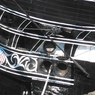
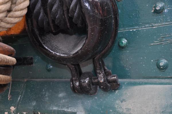
Here is a picture of what they look like on the USS Constitution. The one to the left has a very thin cord coming down and through the hawse to pull the buckler closed. While the one to the right has a similar cord coming through the hull above the hinge to open it. This is very similar to the gun ports. I believe the black ring you see is a seal.
-
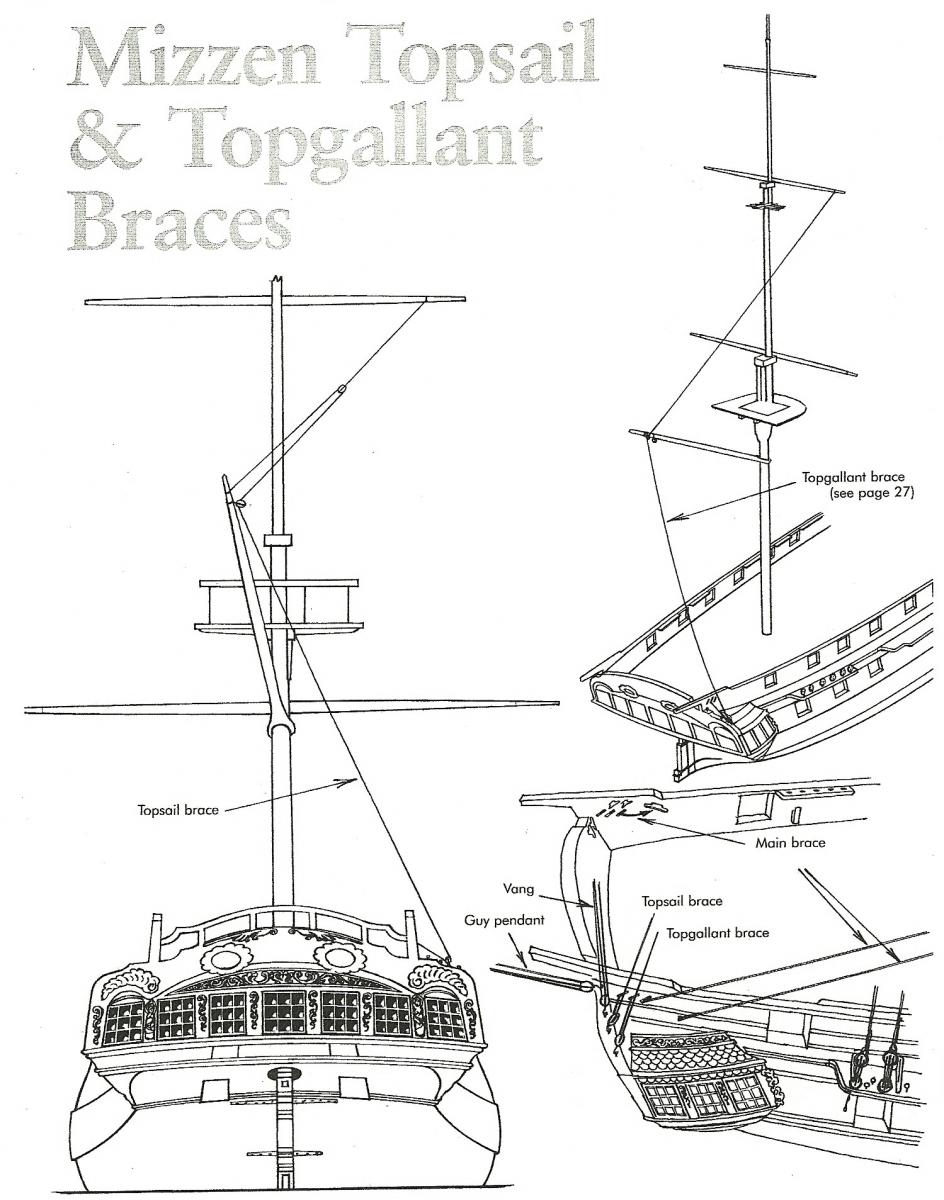
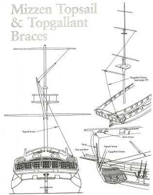
You are absolutely right. I picked the drawing above because that subject came up before when I asked about rigging the USS Constitution that way. And indeed, as Henry pointed out, that is not how it is done on that ship. Nevertheless, as a beginner, I learned a lot from Petersson's book.
-
Yikes! My gudgeons are sweating!!
Modeler12 replied to src's topic in Metal Work, Soldering and Metal Fittings
Looking at your picture, I am almost sure that the 'green' is caused by residual acid in the part. I cannot imagine that the wood has anything to do with that??? When you blacken brass, or any other metal for that matter, the compound is based on nitric acid, and then some. Unless those pieces are completely acid free they might continue to 'rust' afterwards. The fact that you probably treated both parts at the same time and they came out looking like that is a mystery to me. To cover up the process with oil is something we will never know about????? You might try to touch up the parts with some 'base' like a mild solution of sodium bicarbonate (baking soda]. Let it sit for a while and see if there is any visual reaction on the pieces. If there is, acid left overs would be the reason. Continue with the baking soda and rinse (if possible) afterwards. The base should have no affect on the wood or finish that I know of. Good luck. -
The book by Petersson is great, not inexpensive, but clear with mostly drawings. A minor drawback (at least in the older version) is that there are no dimensions about line sizes, blocks, etc. I had my first look at the book by ordering it through our local library. They are connected with many libraries around California. Mine came from Long Beach to the San Francisco Bay Area. Below is an example. Each element is handled individually which makes it easier to understand.
-
Thanks Henry. Here is what I envision for the tackles etc. I made one more deadeye like the last one I showed. But I will also use two that are a bit simpler. The latter will be installed along the starboard side where they are practically invisible. The lanyard seems a bit too thin, but that is the size line called for in the plans. This is due to the scaling factor of the blocks. The real ones look to be about 8 inch in diameter whereas mine would come to almost twice that size. I am not going to worry about this and go with what you see below. After all, the same applies to the deadeyes for most of the rest of the rigging. Of course, all of this is temporary, so I can still make changes.
- 732 replies
-
- 1
-
-
- constitution
- model shipways
- (and 1 more)
-
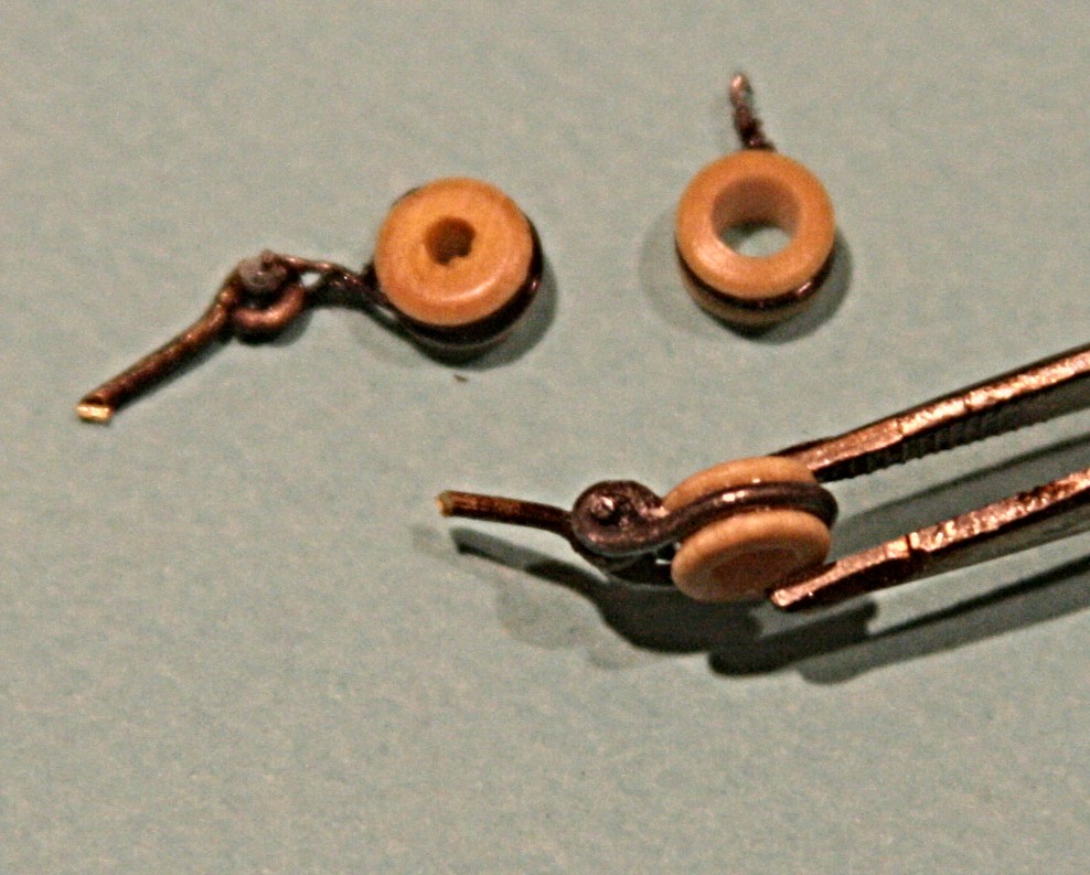
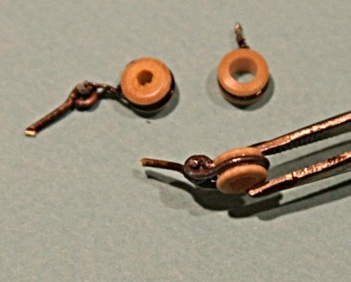
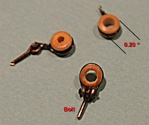
Here is my third and last (perhaps) attempt to duplicate the real 'block' at the bottom of the bentnick shroud. I used a thicker wire, made two loops at the ends so a pin (nail) would fit through these two loops as well as an eye bolt. The bolt is still loose so I can swivel this around the pin. I drilled the larger hole after the wire was in place. I had a feeling that to do the drilling before hand would cause the wood to split. This should be as close as I can get to the real thing. But then I think, 'But nobody is going to see this'. So be it, but it is fun trying.
- 732 replies
-
- 6
-
-
- constitution
- model shipways
- (and 1 more)
-
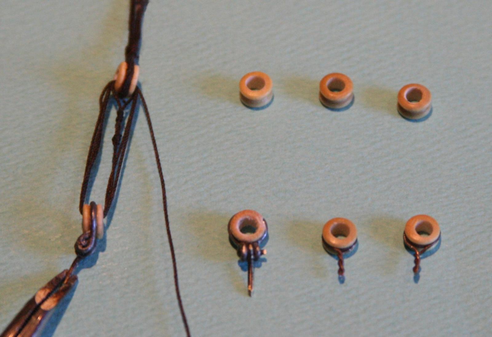
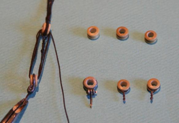
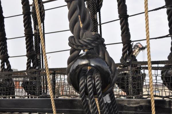
Before I go too far with the above idea, I decided to make a couple deadeyes for the tackle on deck. I used some steel wire and double looped that around a deadeye. I then added an eye bolt and silver soldered the metal wire. That seemed bulky and since Henry's pictures (two of which I show below) show that the bottom bullseye is very close to the waterway, I made my second try by simply twisting the wires and then bond that directly into a hole with some epoxy. This I may have to rethink. My concern was the drilling of the larger hole in the bullseye. There is a groove on the outside (not shown) and if I made the hole too big I would end up with two little pieces. However, a 5/64 inch diameter drill seemed to do the trick.
- 732 replies
-
- 1
-
-
- constitution
- model shipways
- (and 1 more)
-
I noticed that Henry, and that is why I was wondering. At this point I can still add those extra staves as long as they are long pieces of wire that I can glue to the shrouds and then trim off later. I also made some plans to pre-assemble the futtock lines, staves and bentnick shrouds. But I cover that in my build log. I also will be using some deadeyes with larger holes for the tackle on deck. Again your pictures are very helpful for all of this.
-
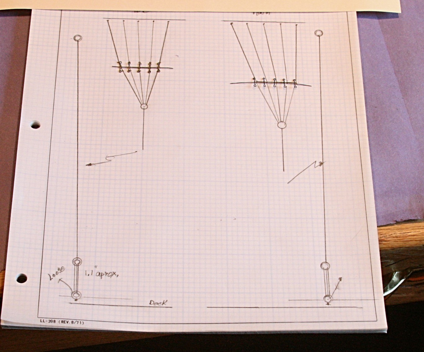
Back to the futtock shrouds for a minute. As long as this was clear in my mind, I decided to draw the arrangement to scale. Later I will use this to pre-assemble the whole thing you see below on the bench. You can see the brazed 'extensions' lying on top of the drawing. The fore mast is to the left. After I hook up the main shrouds on the starboard side, I should be able to install this arrangement including the bolts that go into the waterways. In order to make final adjustments in the tension, I will leave the tackle at the bottom loose. Any way that is my plan for now. BTW the drawing is for the port side. So I will have to use an mirror image for the starboard side.

- 732 replies
-
- 3
-
-
- constitution
- model shipways
- (and 1 more)
-
Indeed Henry and again many thanks. Your pictures are perfect and they give me a lot more confidence in rigging the futtock and bentnick shrouds. See other post. The plans (the sketch above is part of those) show the bottom tackle to be a '5/32 inch heart' instead of the bullseye you show. This part of the rigging looks almost the same as the main and preventer stays near the bow. So I will take some 5/32 bullseyes, drill the holes a bit bigger and try to use those for the tackle. I notice that the location on the waterways is a bit to the right of center. I can understand the engineering for this, because to have them in the center would mean that both the shroud and cannon tackles would apply a lot of stress on the same location. For the starboard side I am also thinking of preassembling the futtock shrouds (with the staves I made and show above) and attach them to the bentnick shroud before rigging all of that to the main shrouds. I will show my attempt to do this later. But right now it is back to the ratlines. BTW the hole you see near the tip of the needle is for the chimney; again something I held off until later.
- 732 replies
-
- 4
-
-
- constitution
- model shipways
- (and 1 more)
-
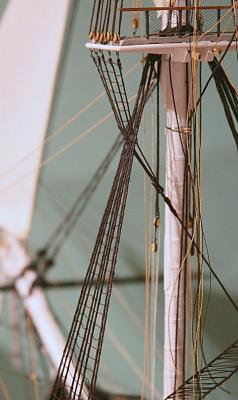
Thanks Evan, that pictures tells a lot. To think that those men were climbing and working up there with strong winds blowing all around them and the ship pitching every which way. I can appreciate the saying that 'one hand for the man and one for the ship'. Now I am a bit hesitant about my build log with people like you keeping an eye about what I am doing. This whole project is a new adventure for me, I am learning a lot as I go along, but I also am enjoying the challenges. There are numerous times when I make changes because something does not look or seem right. Some times I think that I might have to start all over again. But then I change my mind and realize that there will be a 'next time'. After looking at the photographs Henry took aboard the ship, I have decided to make my own special 'heart shaped' blocks for the tackle at the bottom of the bentnick shrouds. They certainly look unique.
-
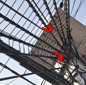
I do have one more question about the ratlines going up to the platform. And this is not just for my friend, Henry, please. It looks like the ratlines on the main shrouds going up to the futtock stave continue along the futtock shrouds (and that is what the plans call for). In one of Henry's pictures it also shows more 'futtock staves' going up along the main shrouds to the little hole above. Q??? Would sailors climb up along the futtock line (almost upside down) to get to the platform, or would they go on to the small opening shown in Henry's picture??? Either way, I would not like to do that now.
-
My goodness, Henry, that is great work. Many thanks. I will have to digest some of this, but I already know that I have more work in stall. Your details are perfect about the futtock shroud attachments. I knew that the futtock shrouds did not simply go under the stave and down. That is why I tried to make that transition piece in my log, but then again that becomes very detailed and complicated. However, I see that the bentnick shroud does have a large thimble at its end and the futtock lines are looped through that. I did not know that the bentnick's splice was served because it was so hidden in the previous pictures. This clarifies this view. I already made some metal loops to take their place and probably will leave it at that for my port side. The plans did call for the attachment to the waterways to be where you have shown it in one of your pictures. I am surprised because that seems to be a spot that interferes with the operation of the gun to the right. But what do I know. Again I have drilled holes and was ready to mount the eyebolts a bit further to the left of what is shown. Need to rethink! The attachment to the waterways is simple, permanent, but does require that special block(s). They don't look like 'hearts' but I am still tempted to use the deadeyes I have to take their place. After all, this is a rather permanent situation and my approach still is to make things look a bit 'real', even if it isn't. From all I have now I am more satisfied about my rigging from here on. So, Henry, my most thankfulness goes your way, my friend, my 'young salt'. I appreciate this.
-
That would be great Henry. Thanks for the offer. I mentioned in my build log that the plans call for a tackle with heart shaped blocks. I don't have any but I do have some deadeyes that are shaped that way. Perhaps they might work, but I will certainly wait until you can clarify this for me. I like to add that I was planning to put a fairly large eyebolt in the waterway half way between the two cannonades. Is that about the right location? How are the blocks attached to this? A hook or more permanent?
-
The port main futtock lines are in place along with a larger ring that connects them to the 'Bentnick' shroud. This is the first time I found a mistake in the plans. The sketch above calls for a 1/8 inch thimble. I tried that on the fore mast and found it to be way too small. In fact, the 1/8 inch for the thimble is the outside diameter. So I made some copper rings instead. I still like to see more details about how the Bentnick shroud is attached to the waterway. I don't have any 5/32" hearts and may end up using some deadeye hearts that look about the right size.
- 732 replies
-
- 3
-
-
- constitution
- model shipways
- (and 1 more)