HOLIDAY DONATION DRIVE - SUPPORT MSW - DO YOUR PART TO KEEP THIS GREAT FORUM GOING! (Only 20 donations so far - C'mon guys!)
×
Baker
-
Posts
4,234 -
Joined
-
Last visited
Content Type
Profiles
Forums
Gallery
Events
Everything posted by Baker
-
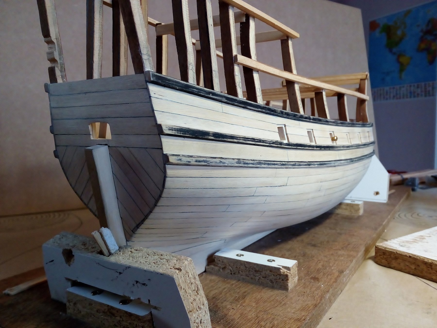
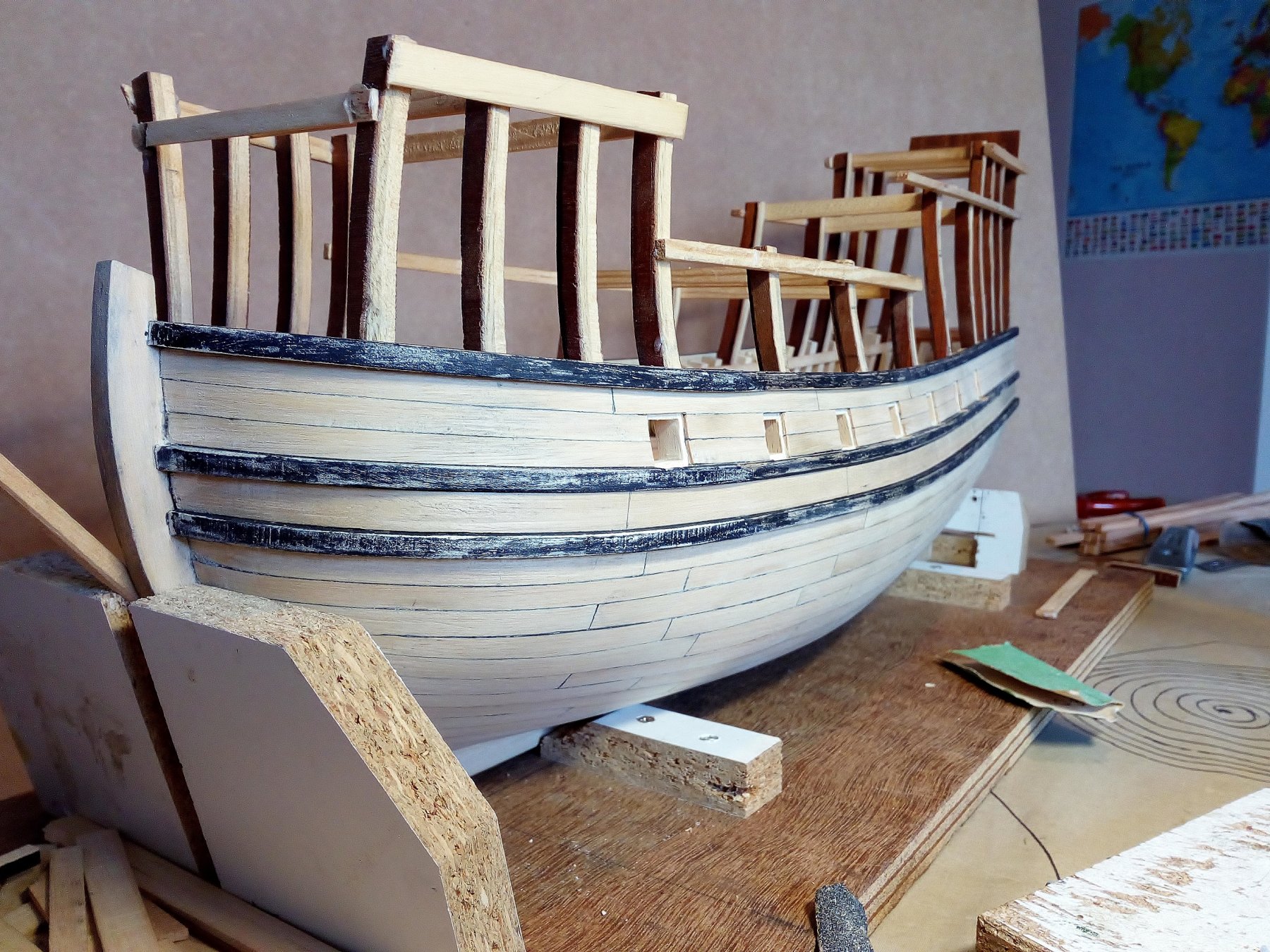
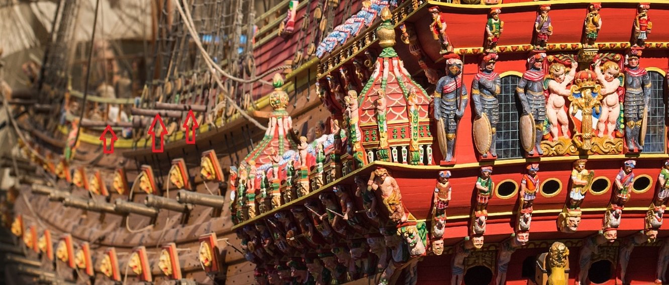
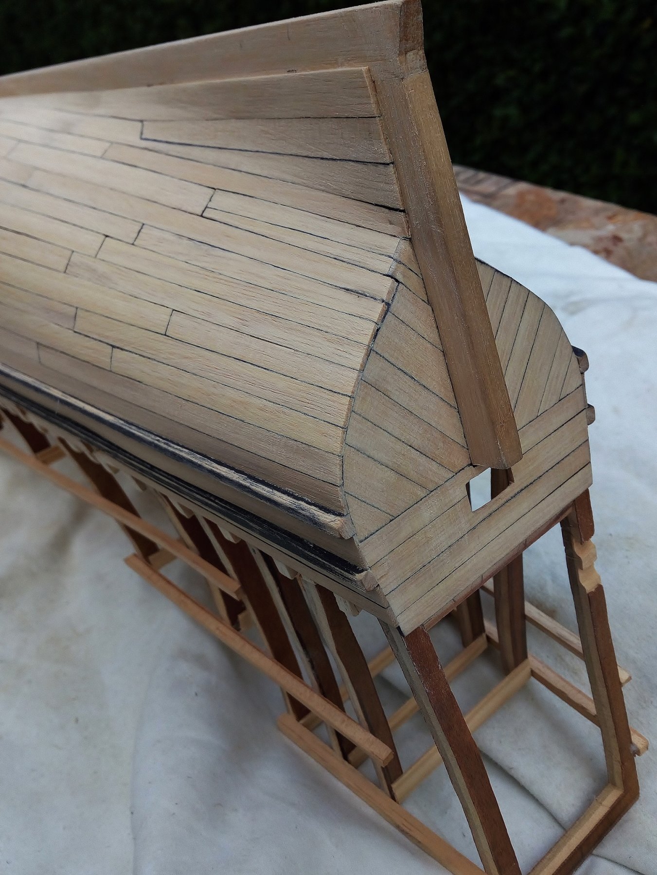
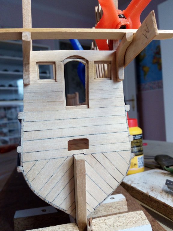
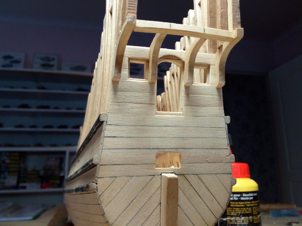
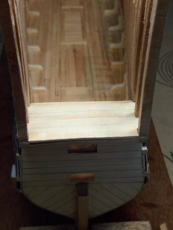
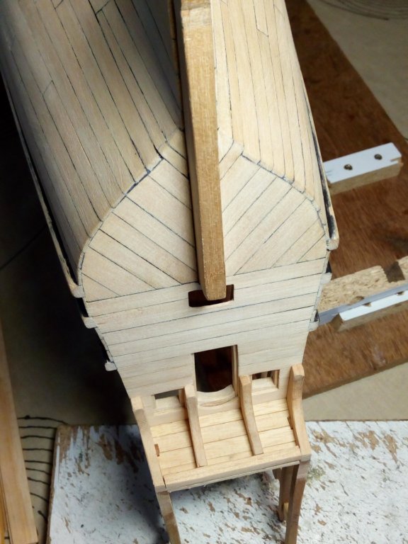
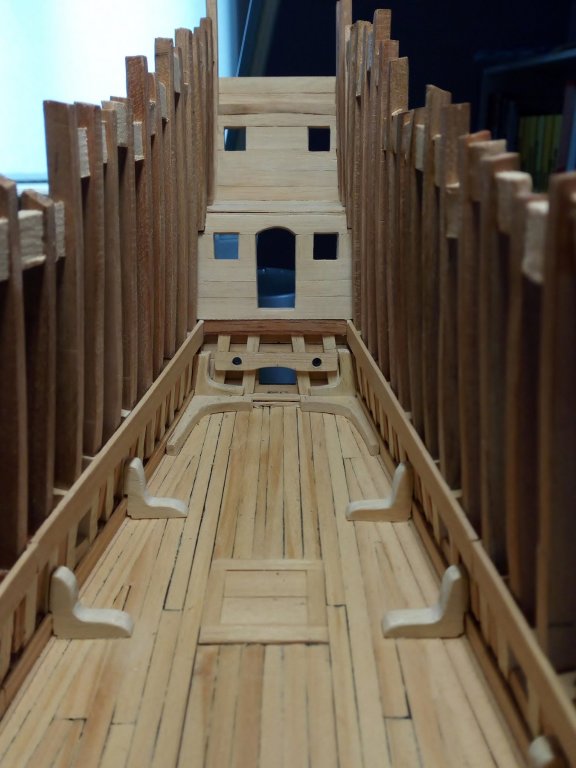
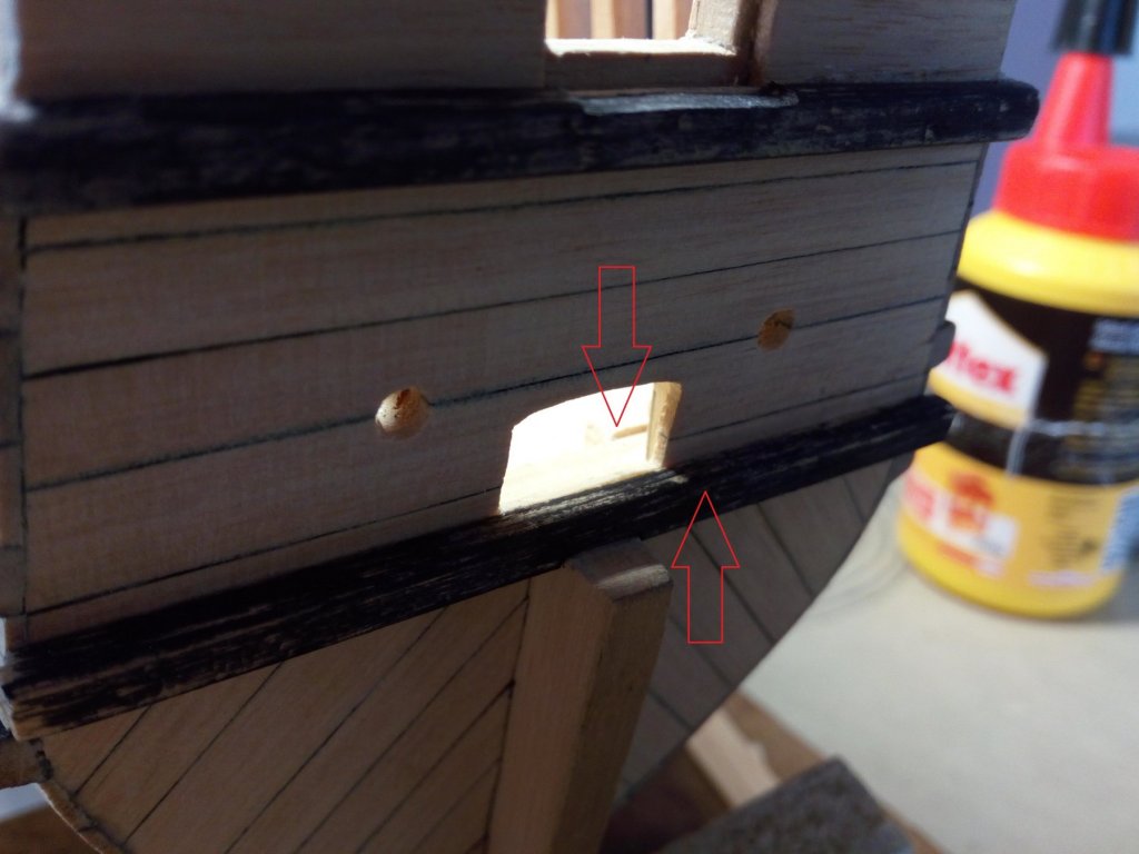
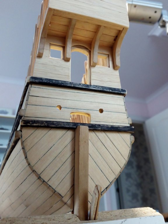
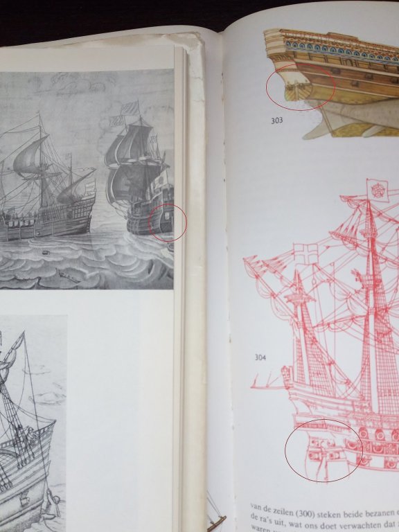
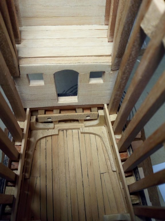
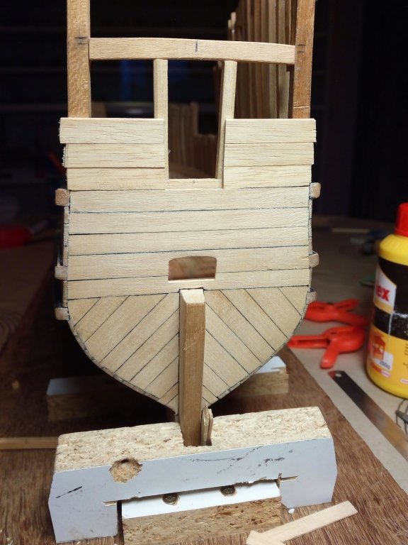
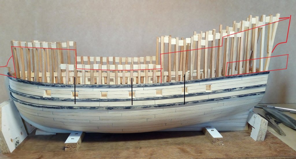
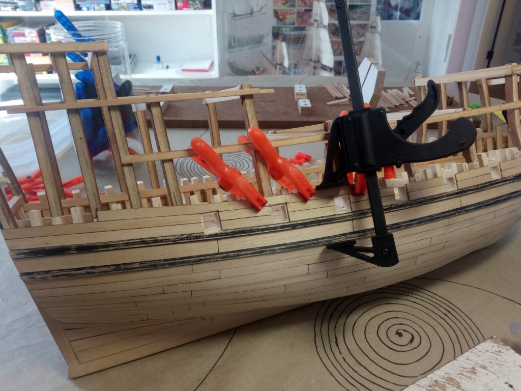
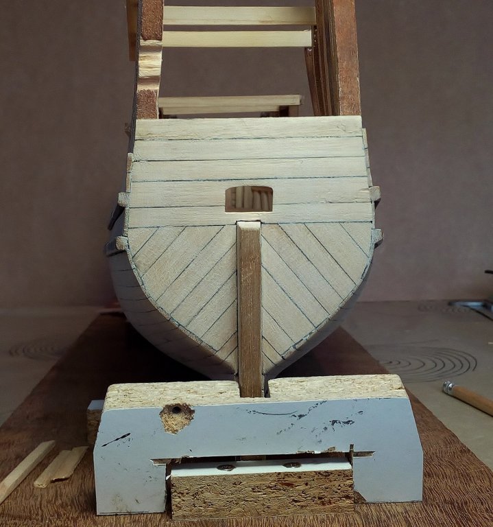
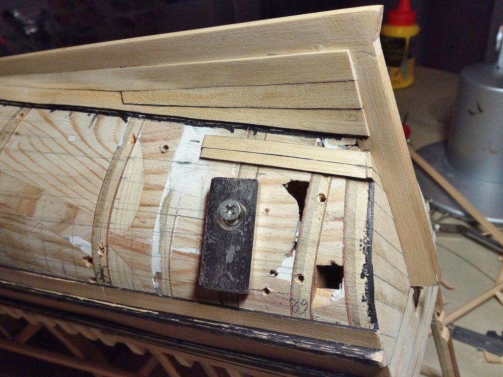
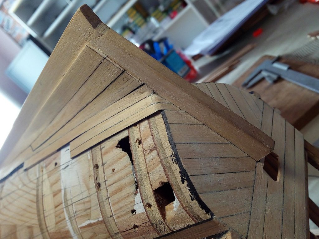
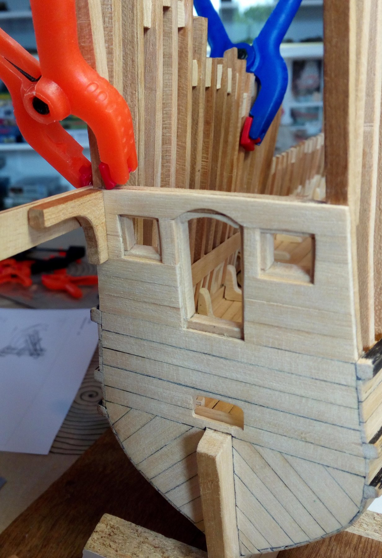
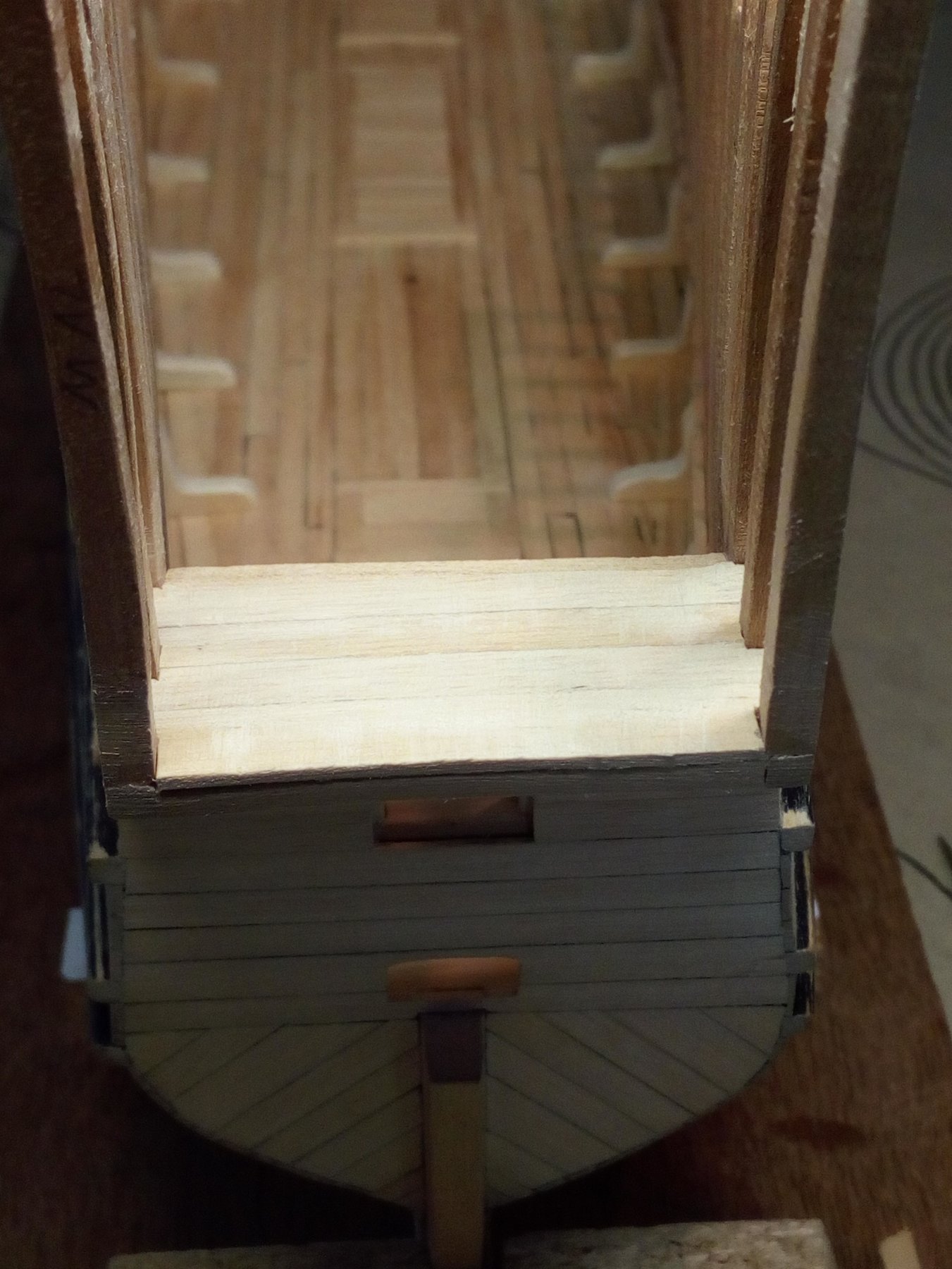
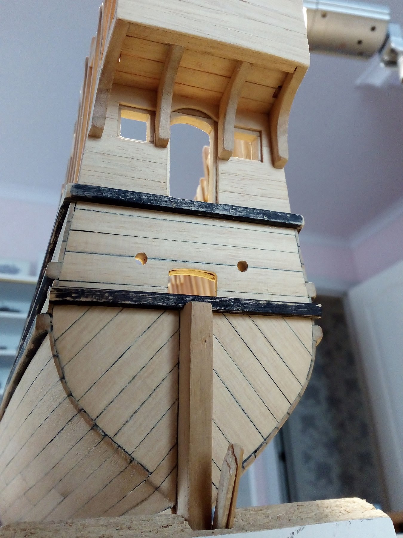
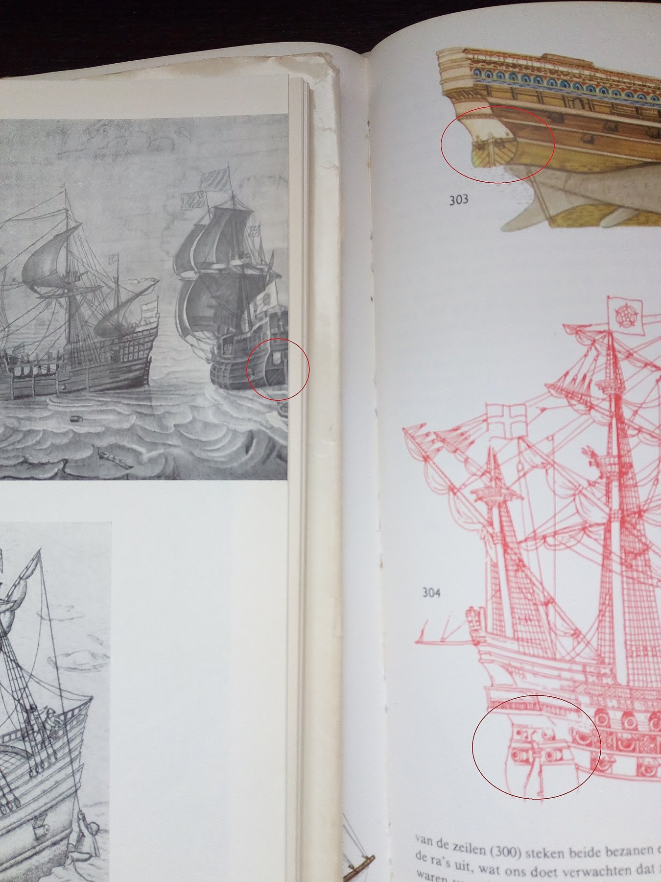
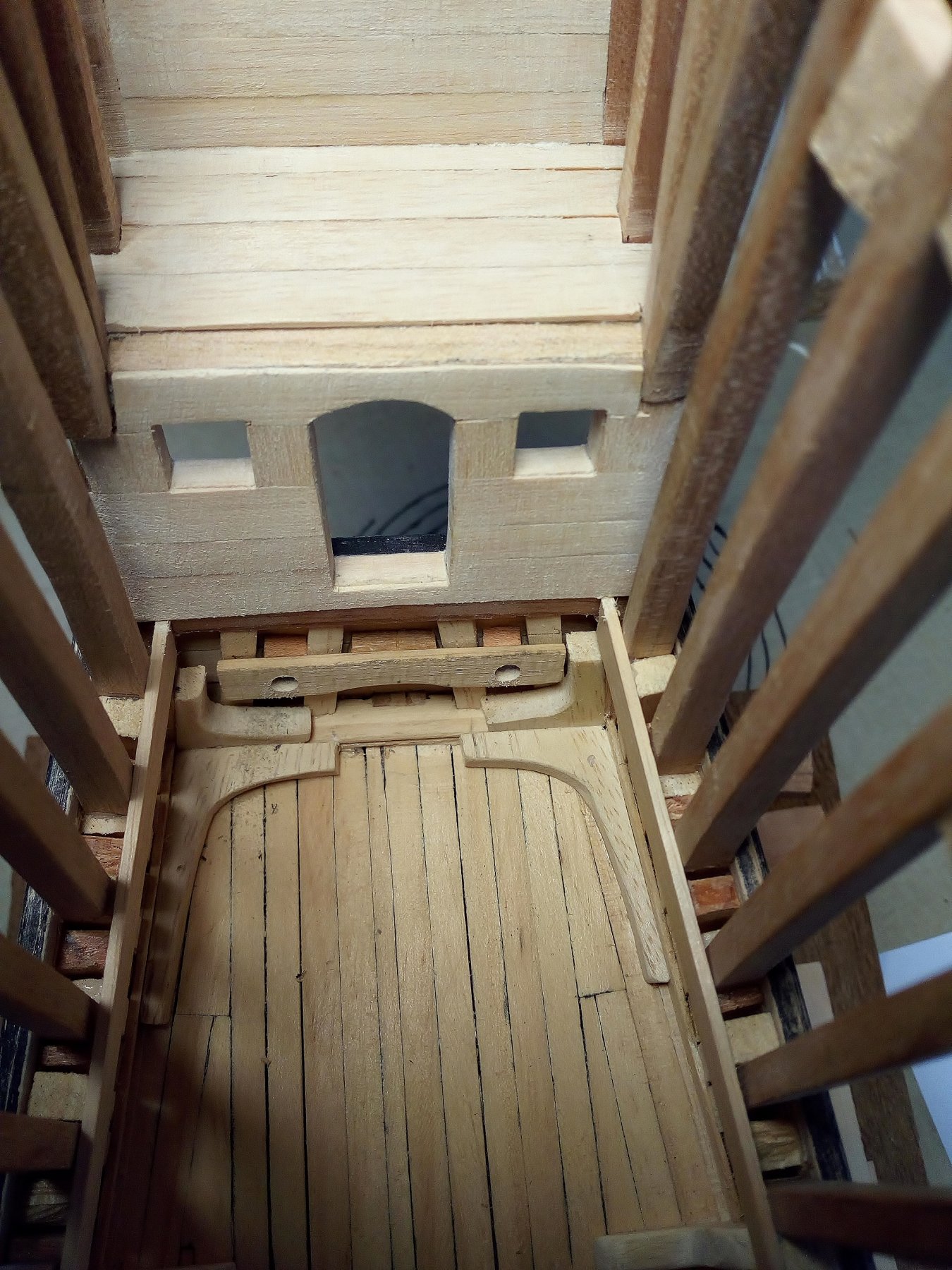
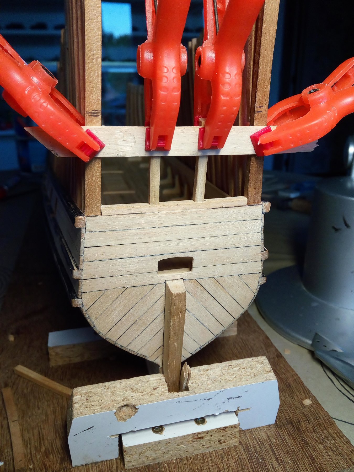
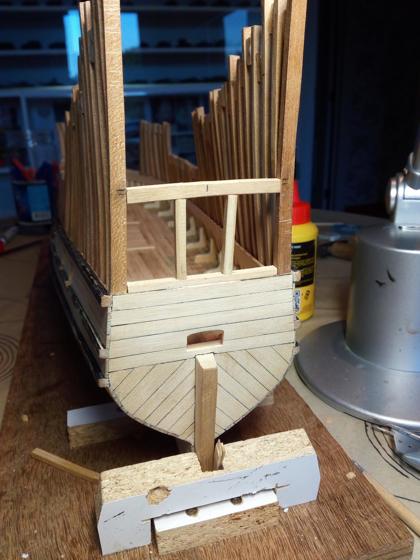
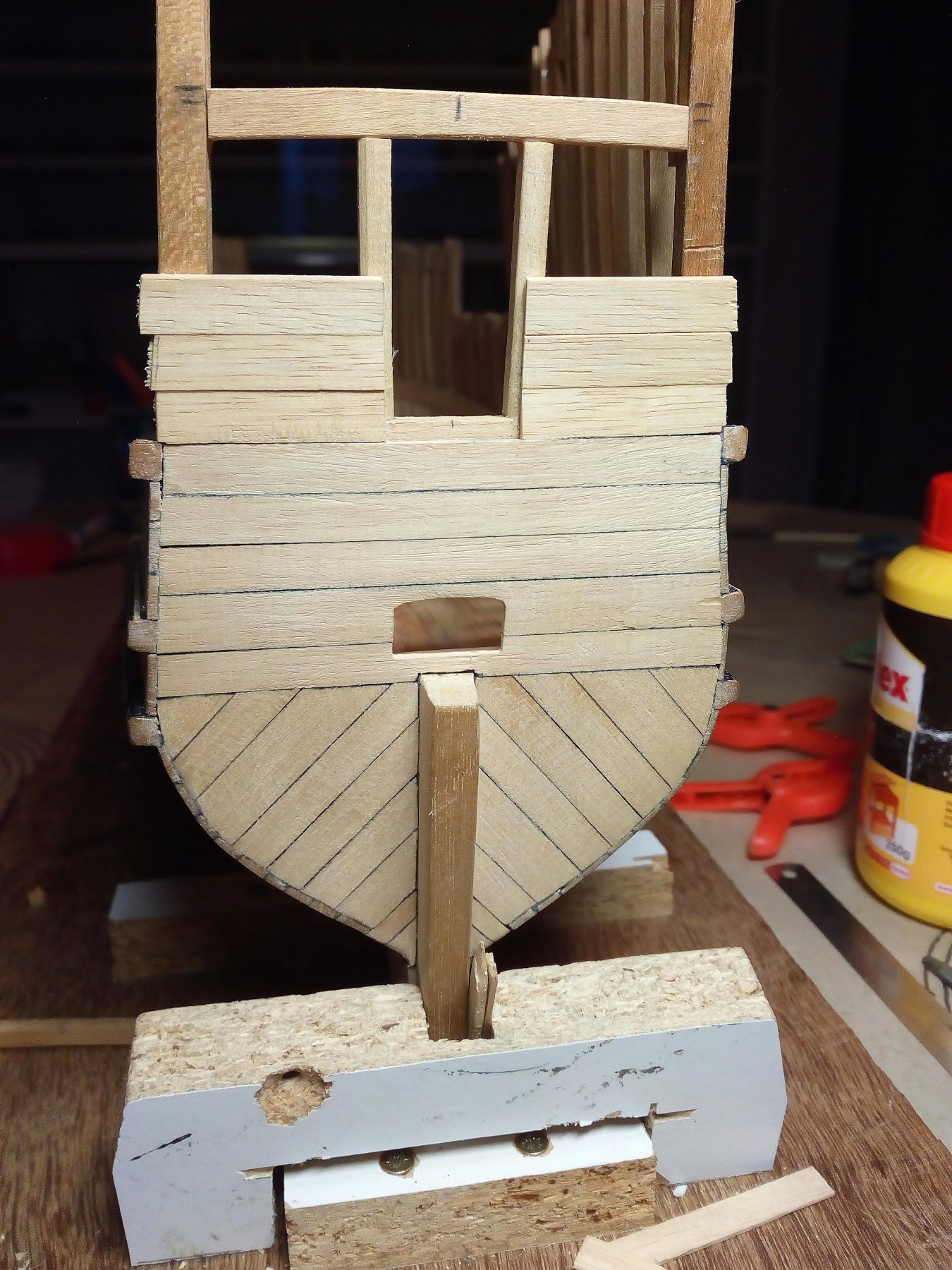
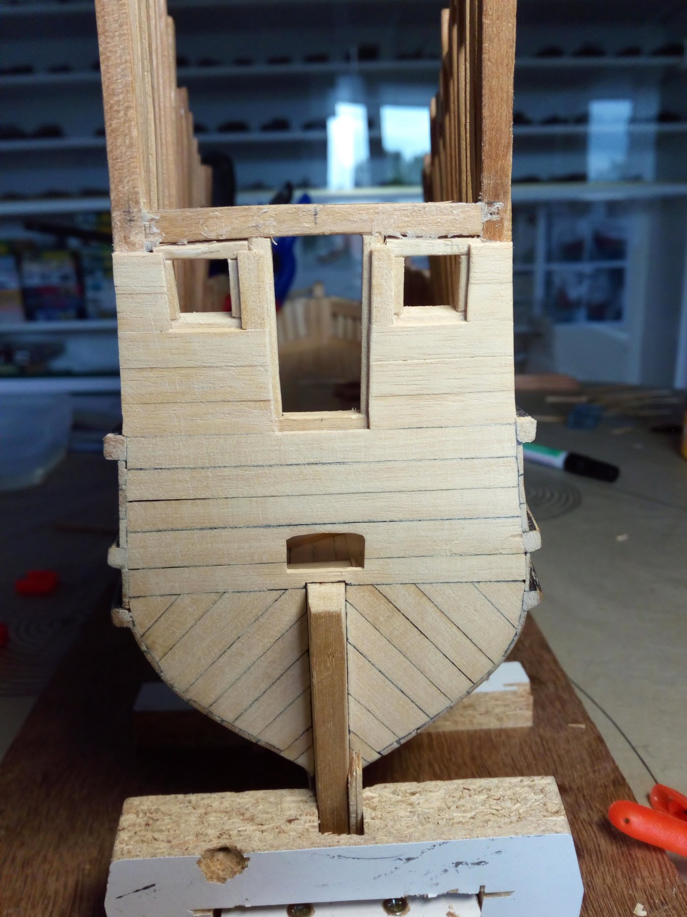
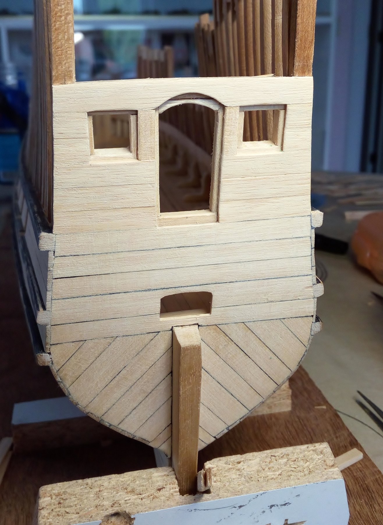
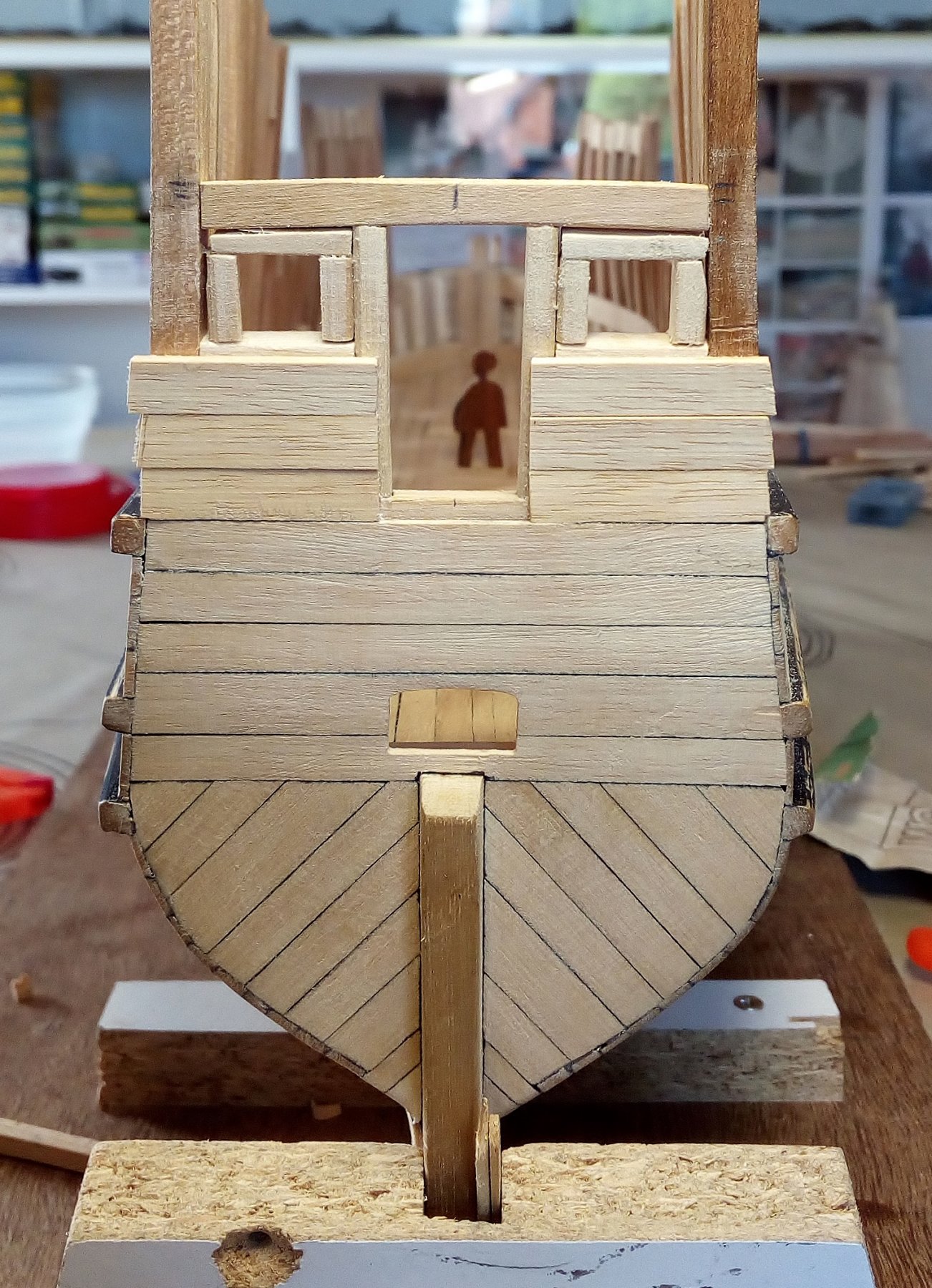
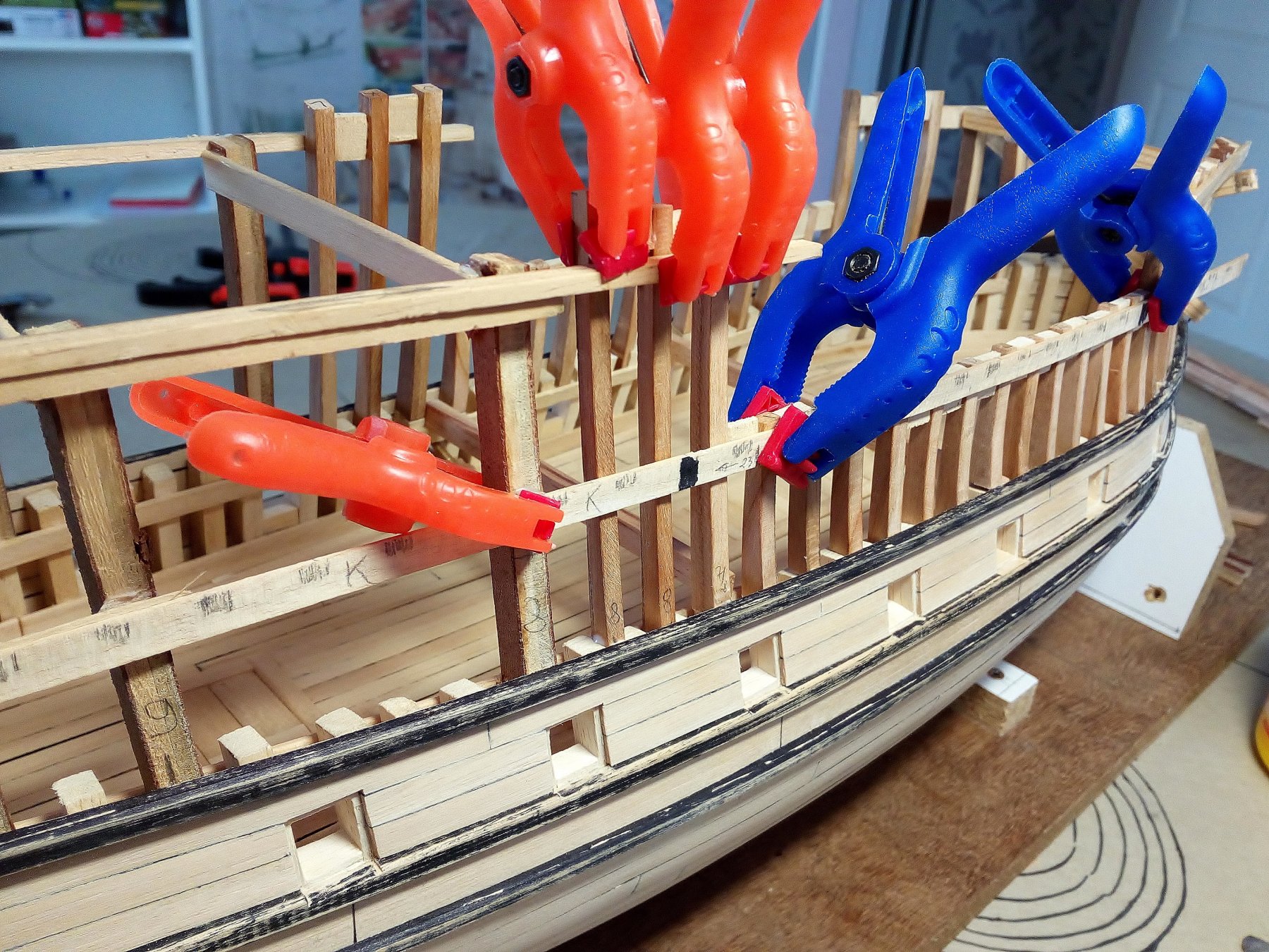
 Making the poop at the stern of the ship. "Poop" If you ever come to Flanders or the Netherlands and you say "poop" in English People will probably look strange to you. I searched in wikipedia where this name comes from The name originates from the French word for stern, la poupe, from Latin puppis. A good explanation (It has something to do with a certain part of our admiral ) Attach supports to the stern. Attach “frames” on the supports 2 extra supports for the deck ( there is just enough room between them to open the door ) Planking, there are two windows for the cabin in the poop. Cabins in the rear will be planked on the inside. The wales on the stern. From now on, most of my information will come of old drawings and paintings from the 16th and early 17th century It seems that no standard can be found in how many wales there are on the stern. Where there are openings made in the stern, there are apparently wales provided I have thus provided 2 wales One under the door of the balcony One under the opening of the helm (At the same level as the lodging knee on the orlop deck). This could be correct. There are also 2 small holes made next to the opening of the helm. Thus, the wale (outside) can be attached to the lodging knee (inside) With some extra detail inside Thanks for following this build Index post 1
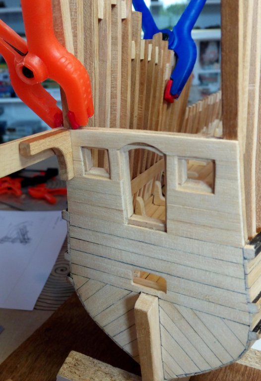

- 756 replies
-
- 10
-

-
- galleon
- golden hind
- (and 2 more)
-
Planking a solid hull
Baker replied to Srodbro's topic in Building, Framing, Planking and plating a ships hull and deck
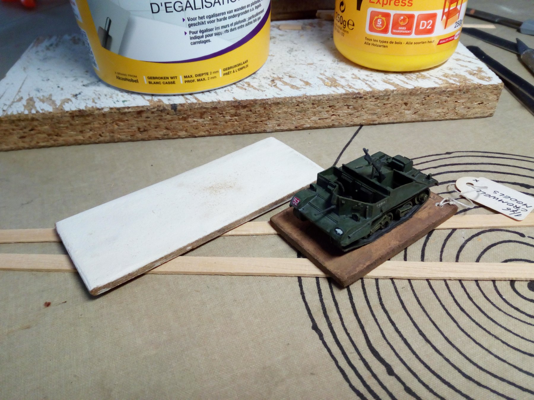
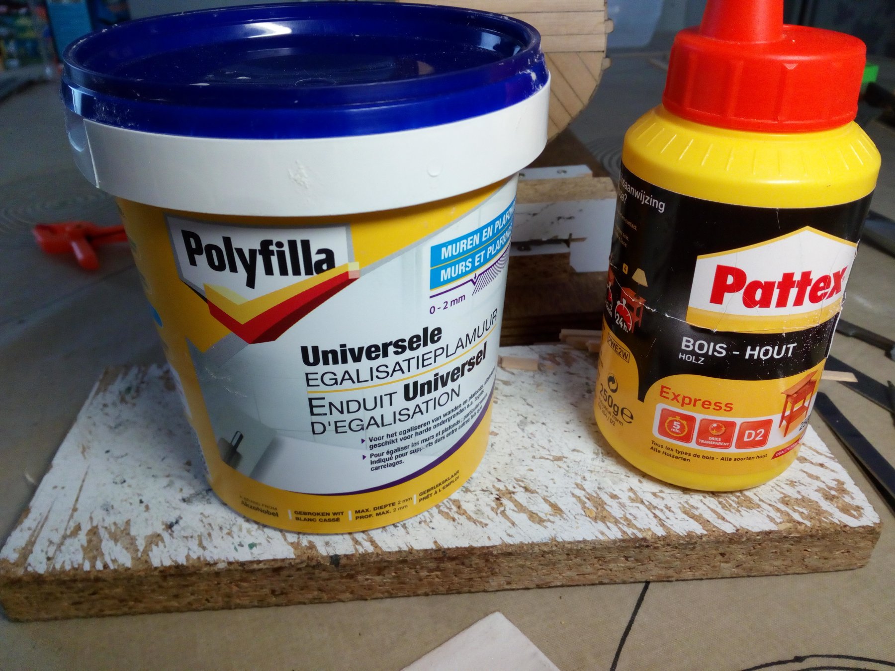
I would also keep the bulkheads. For the same reason as Roger said : This is an easier way to build an accurate hull because the thin body plan sections (or the bulkheads) are in fact templates embedded in the hull. Used products. Ordinary universal filler for wall and gyproc plaster. Available everywhere (This is a Belgian brand) Ordinary white wood glue. I have used this filler for 25 years as a base on wooden boards for my military model. Never had any problems with it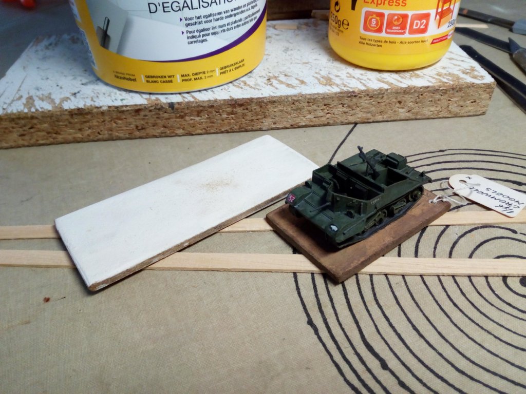

-
Planking a solid hull
Baker replied to Srodbro's topic in Building, Framing, Planking and plating a ships hull and deck
If I understand your question correctly. You may find an example here. I have built a solid hull with filler blocks between the frames (bulkheads). I was very pleased with this way of construction -
I have occasionally followed the building of this model. Nils, Beautiful and well done !! Groetjes
- 2,625 replies
-
- 3
-
-
- kaiser wilhelm der grosse
- passenger steamer
- (and 1 more)
-
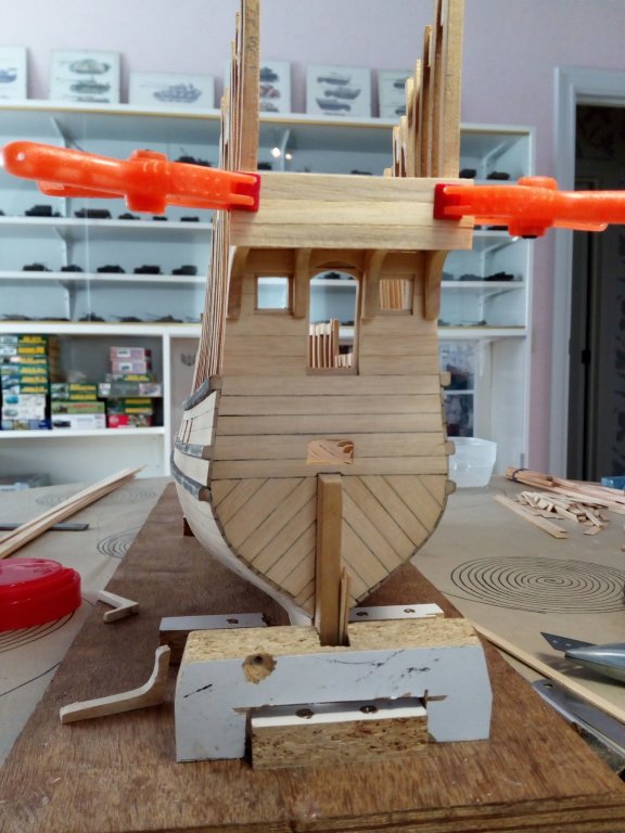
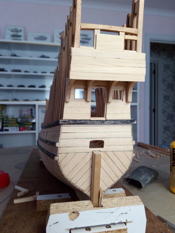
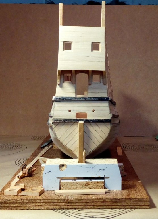
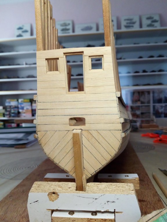
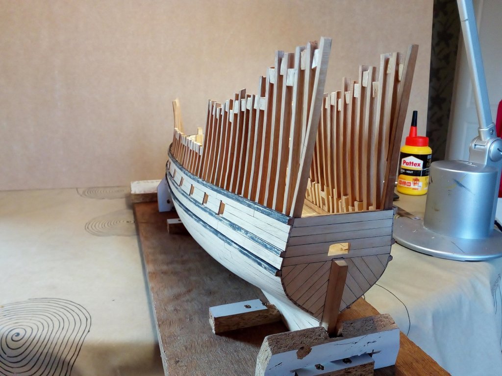
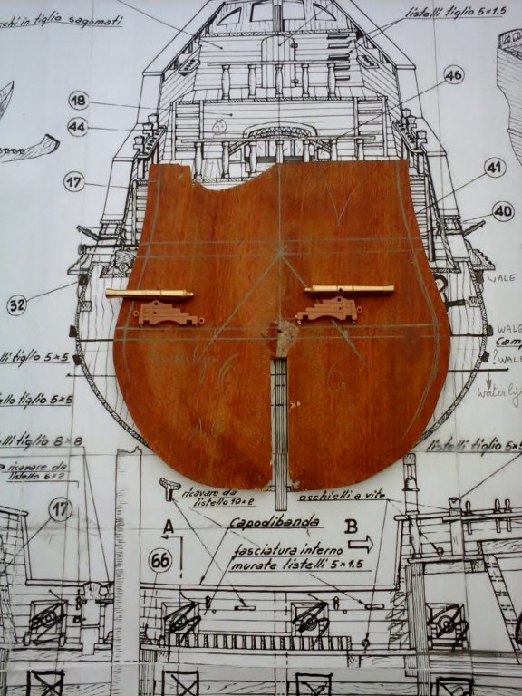
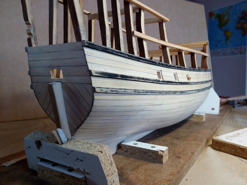
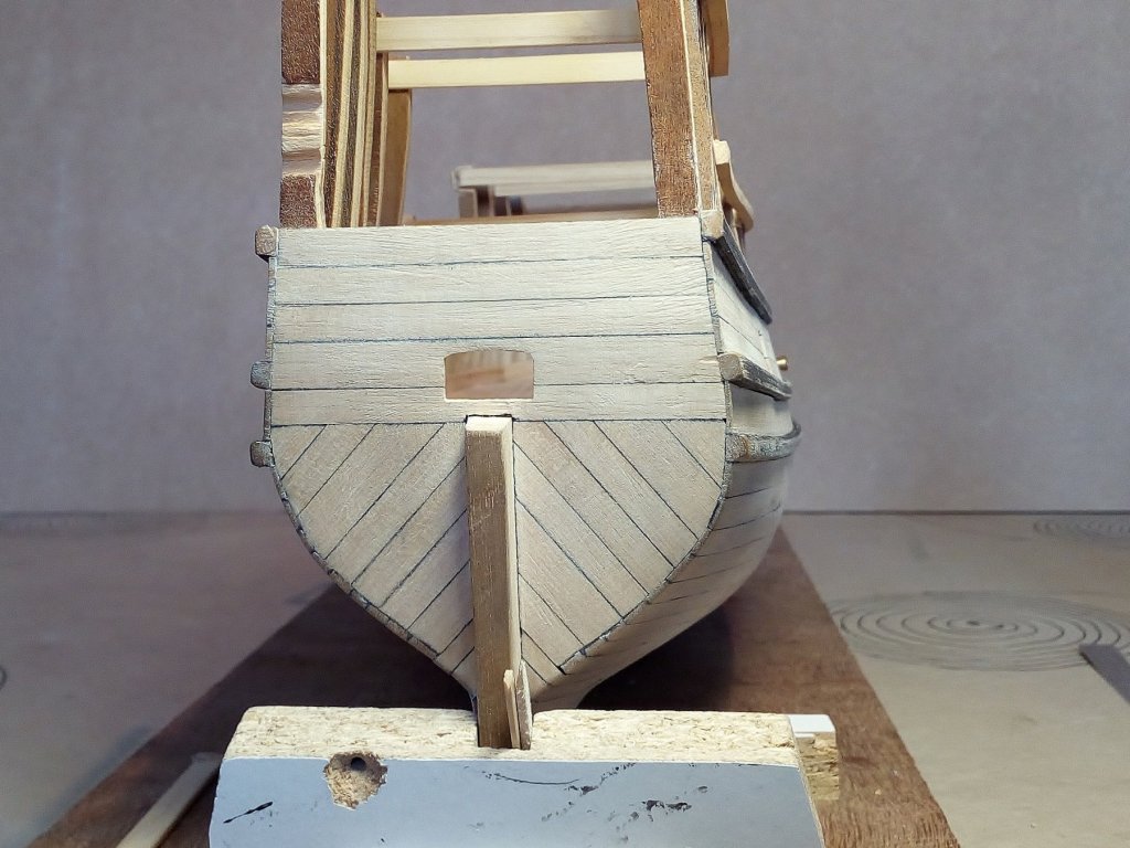
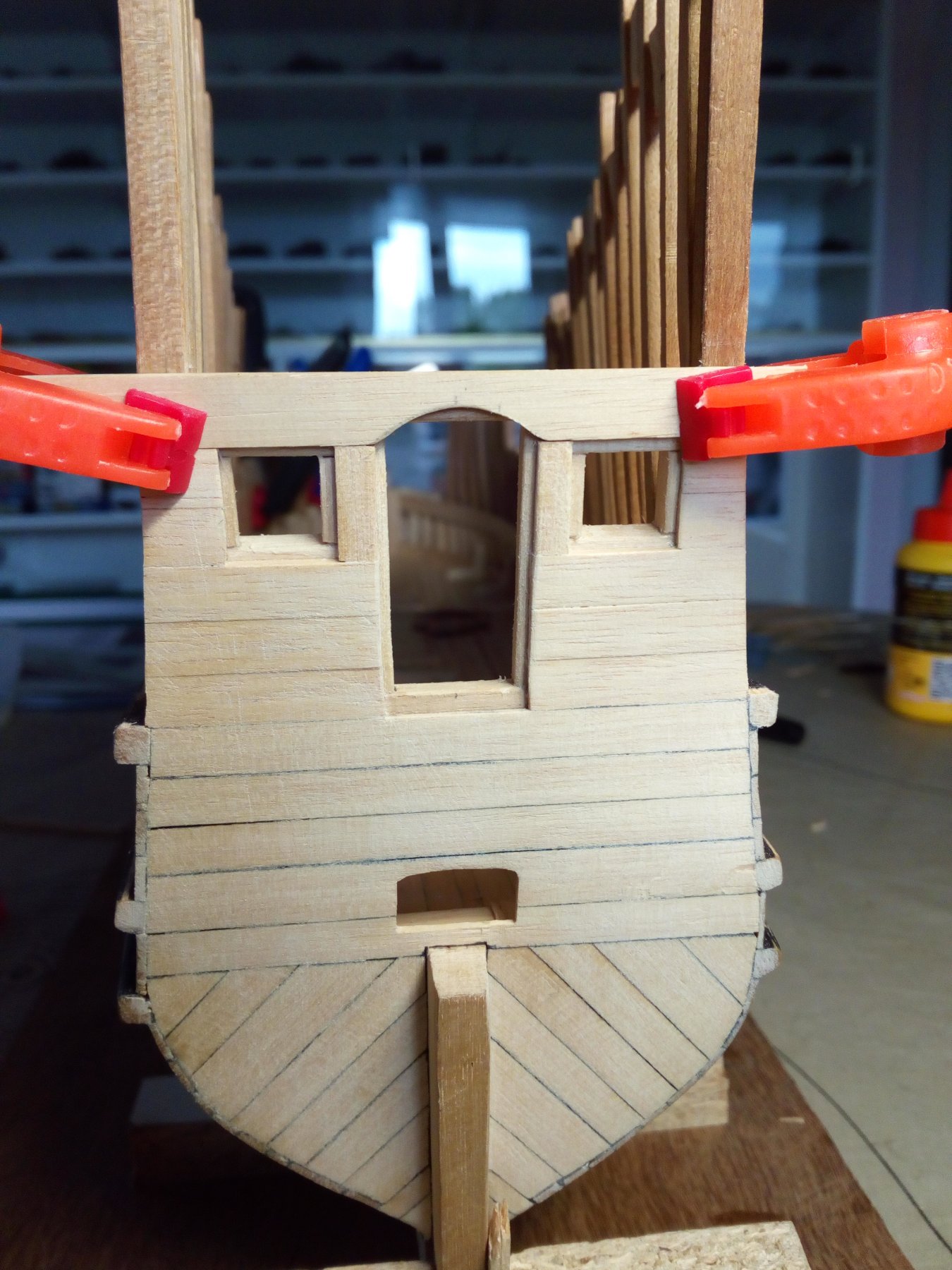
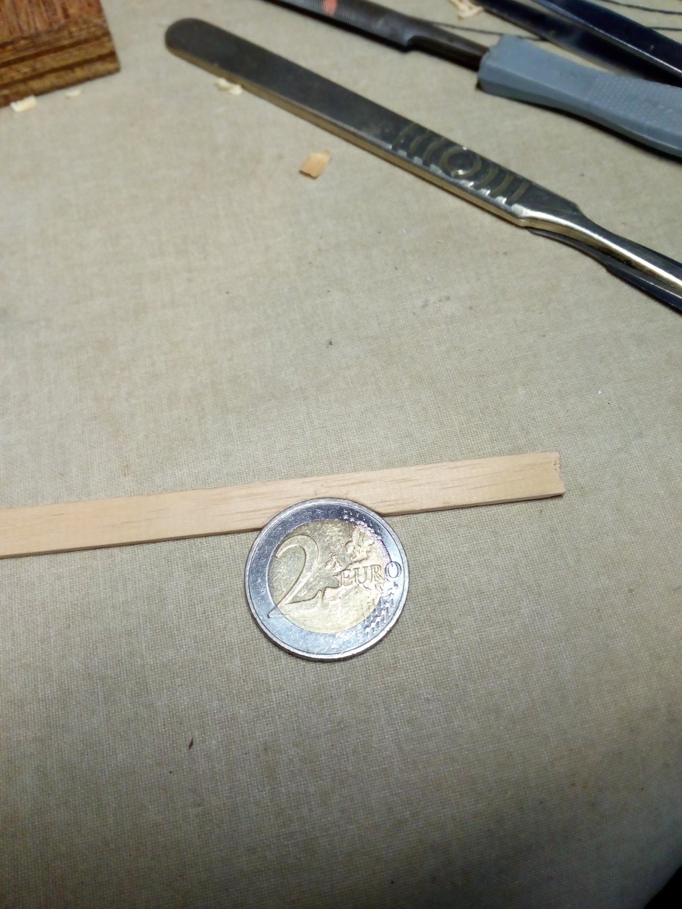
Further planking of the transom. After long doubt There will be a balcony on the transom. There is one door and 2 small windows. First attempt. A rectangular door, not good. So : remove and rebuilt This is better What you can do with a piece of 2 euros Done Index post 1 Thanks for following this build


- 756 replies
-
- 11
-
-
- galleon
- golden hind
- (and 2 more)
-
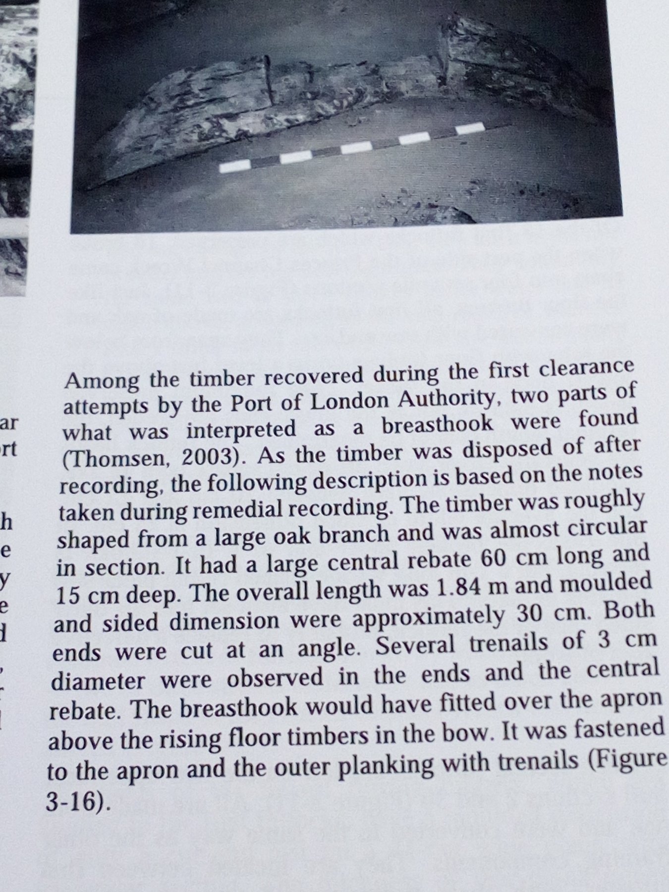
Steve Thank you for the information So, definitely no breast hook on the deck. If possible, I will place one under the bow. And my friends. Enjoy the nice weather in the weekend as much as possible. About me Just back from a couple of days hiking in Luxembourg With good food and drinks included (Of course )
- 756 replies
-
- 2
-
-
- galleon
- golden hind
- (and 2 more)
-
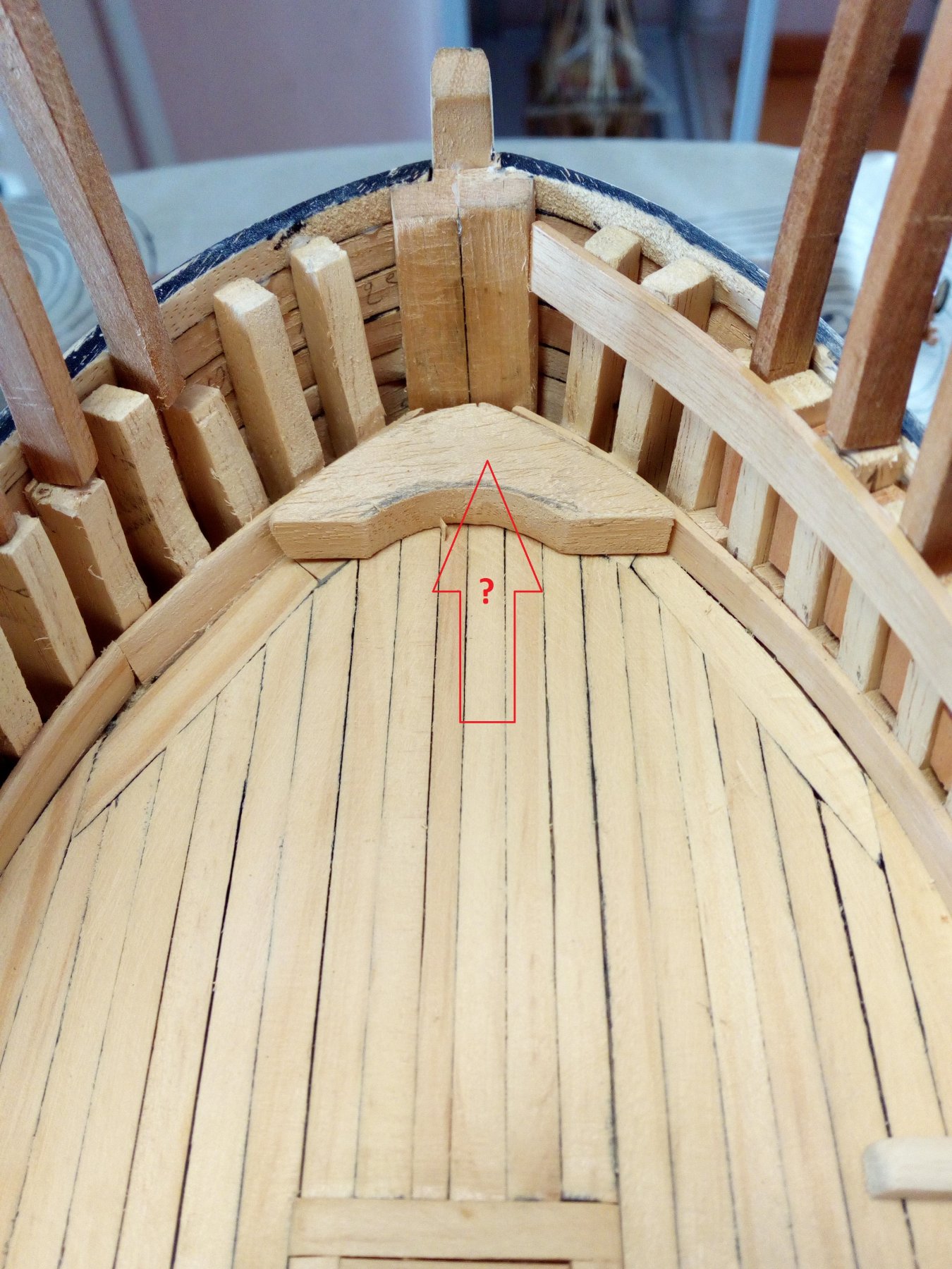
And now a question. Ever heard of a breastshook? This is a solid piece of wood that is attached to the bow. A piece of wood on the deck as an example (Not yet in the right shape) Would i attach this part on the deck? Or is this actually placed under this deck? And is thereby invisible on this model. i did a google search But found no satisfactory answer


- 756 replies
-
- 5
-
-
- galleon
- golden hind
- (and 2 more)
-
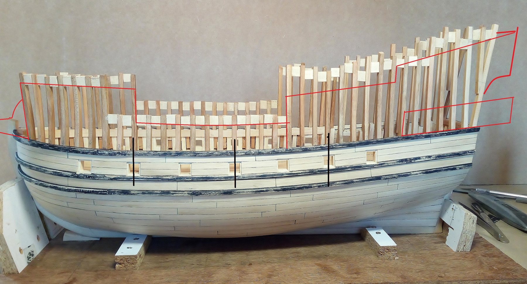
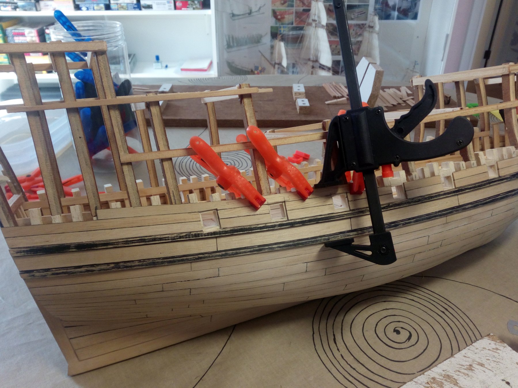
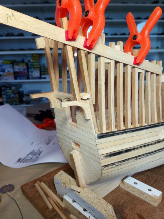
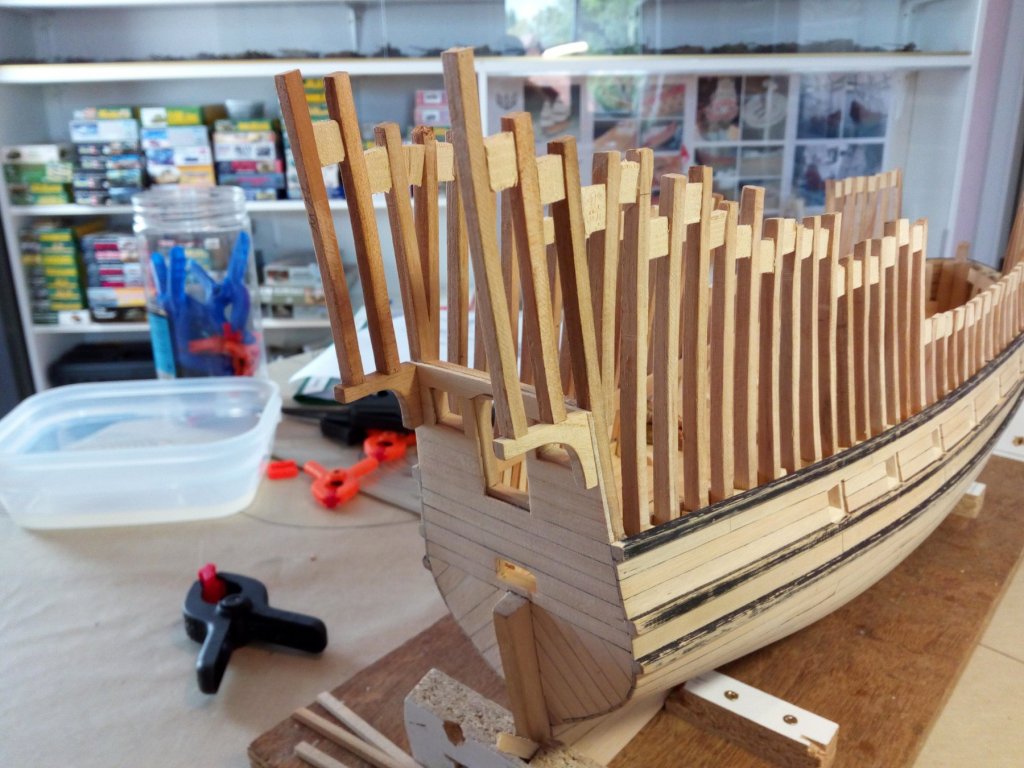
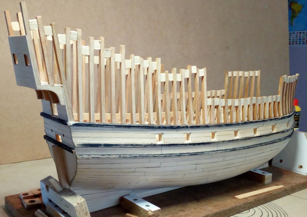
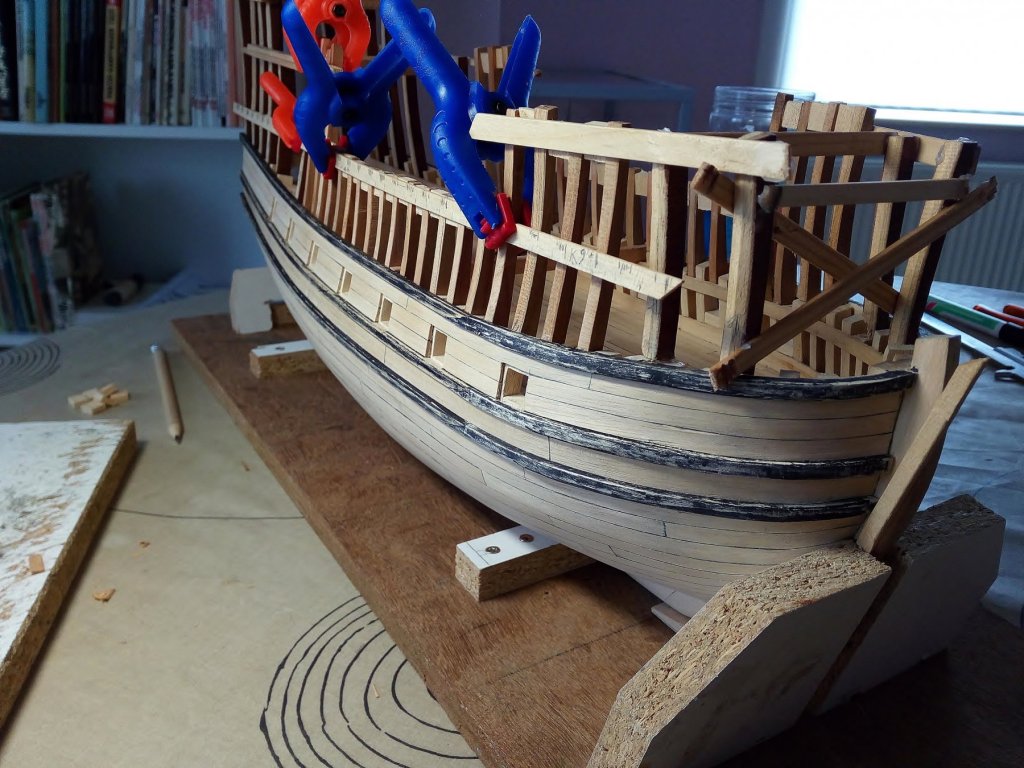
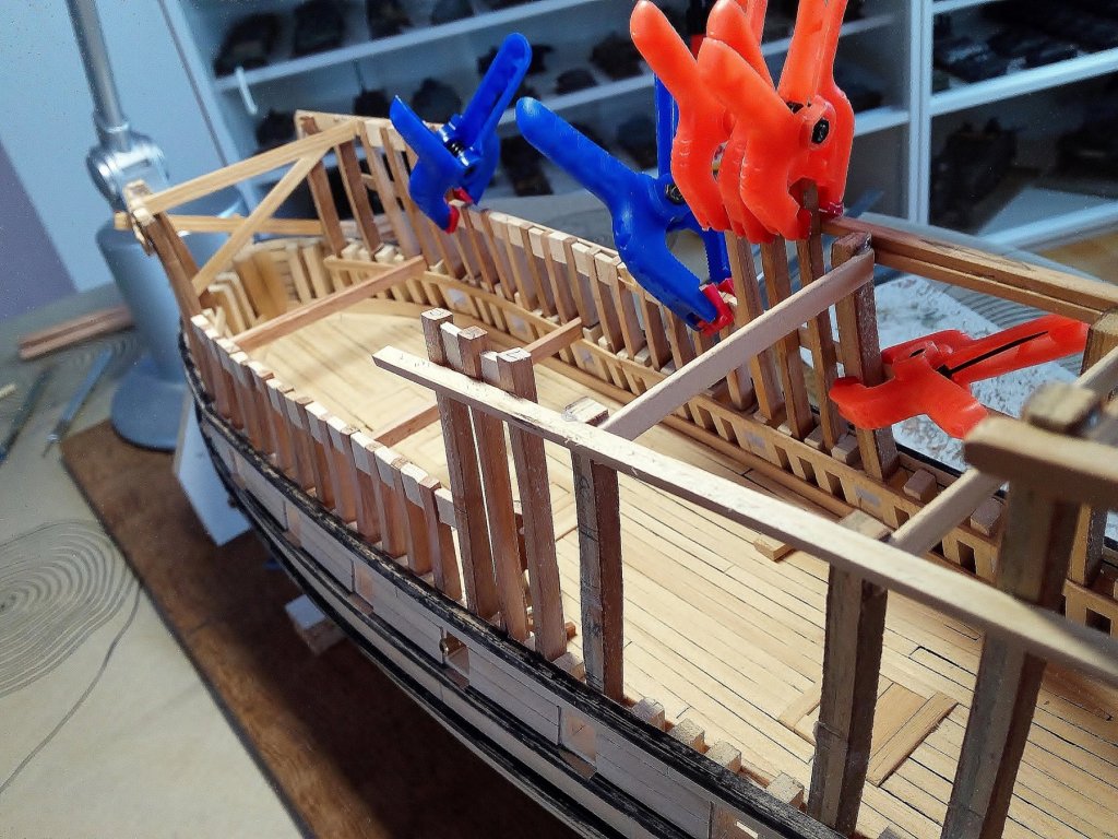
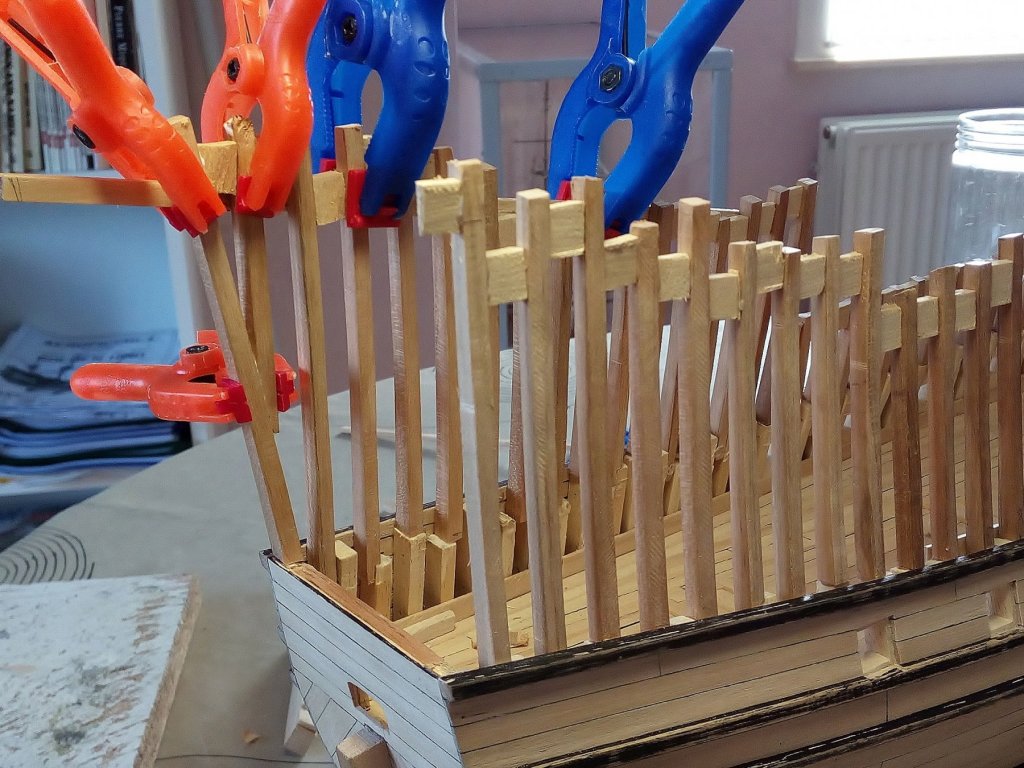
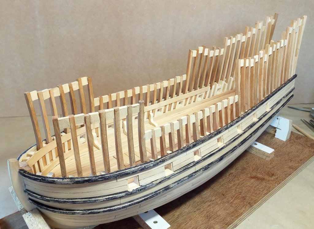
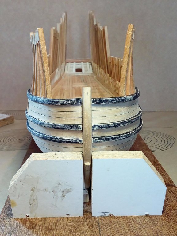
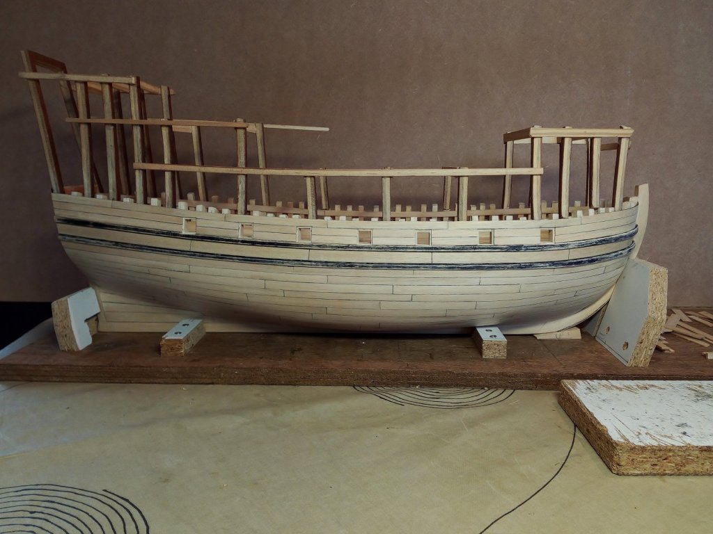
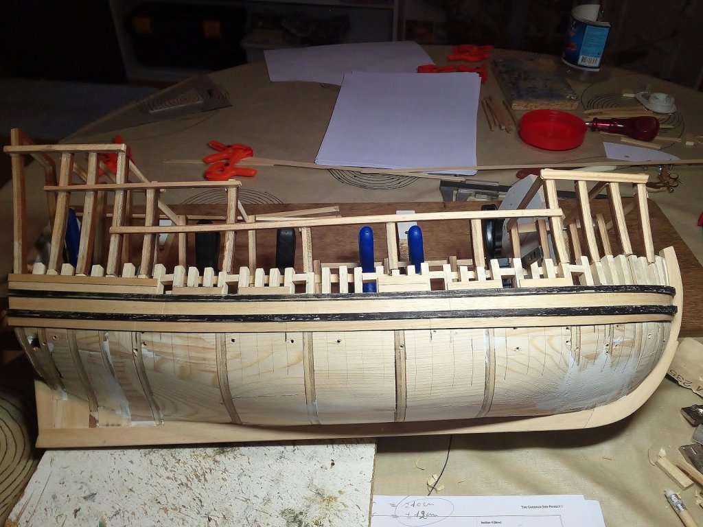
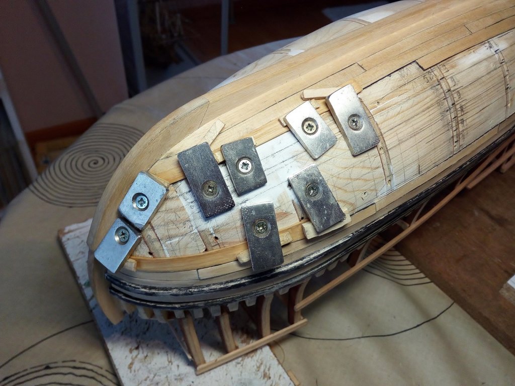
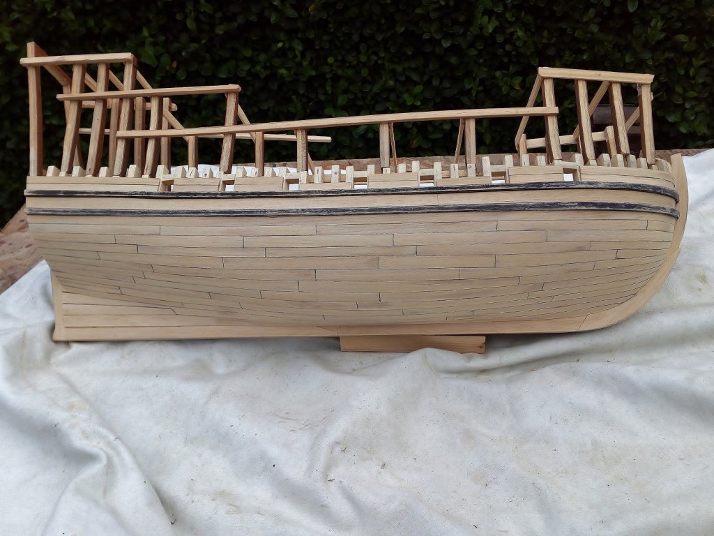
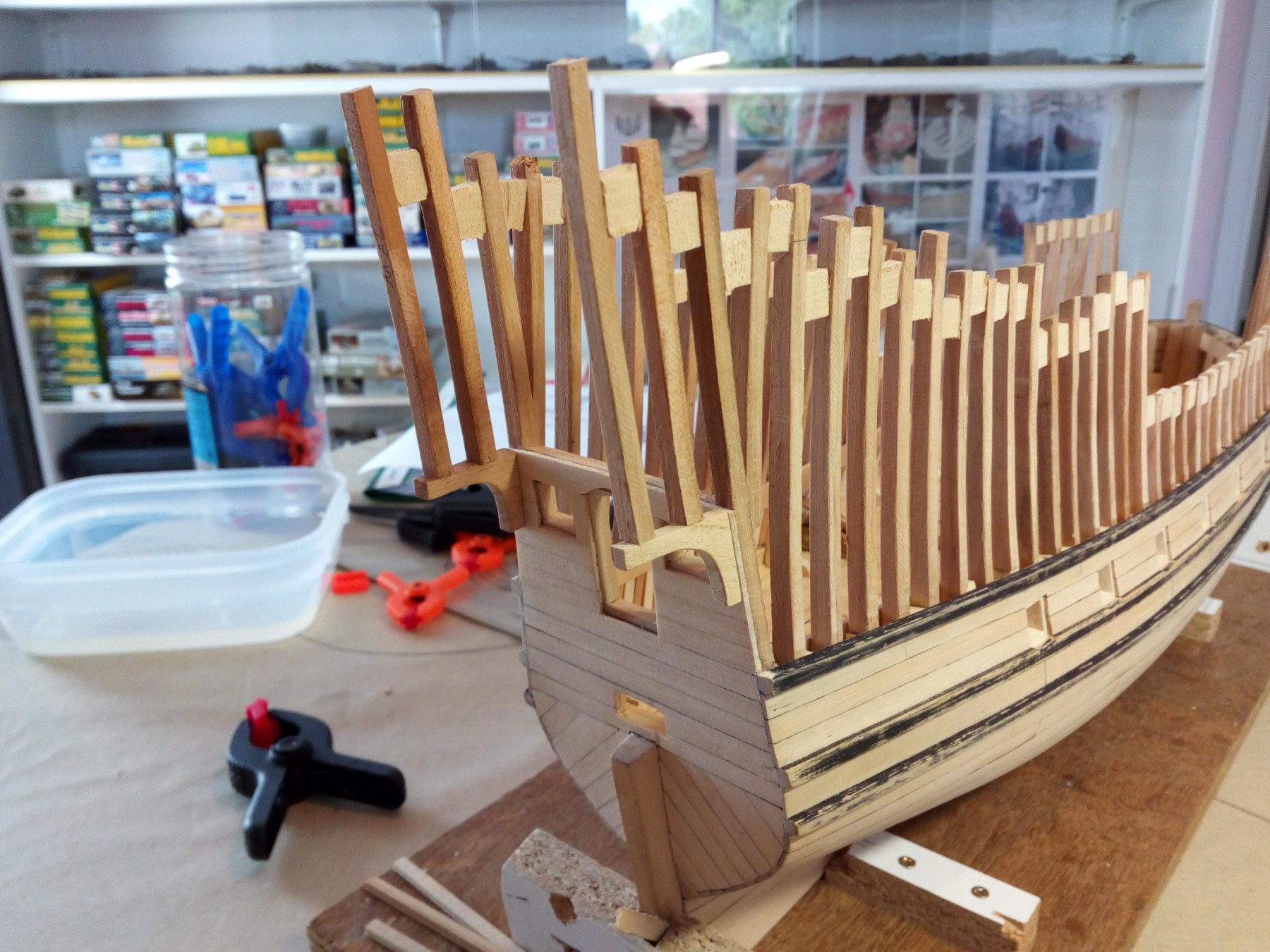
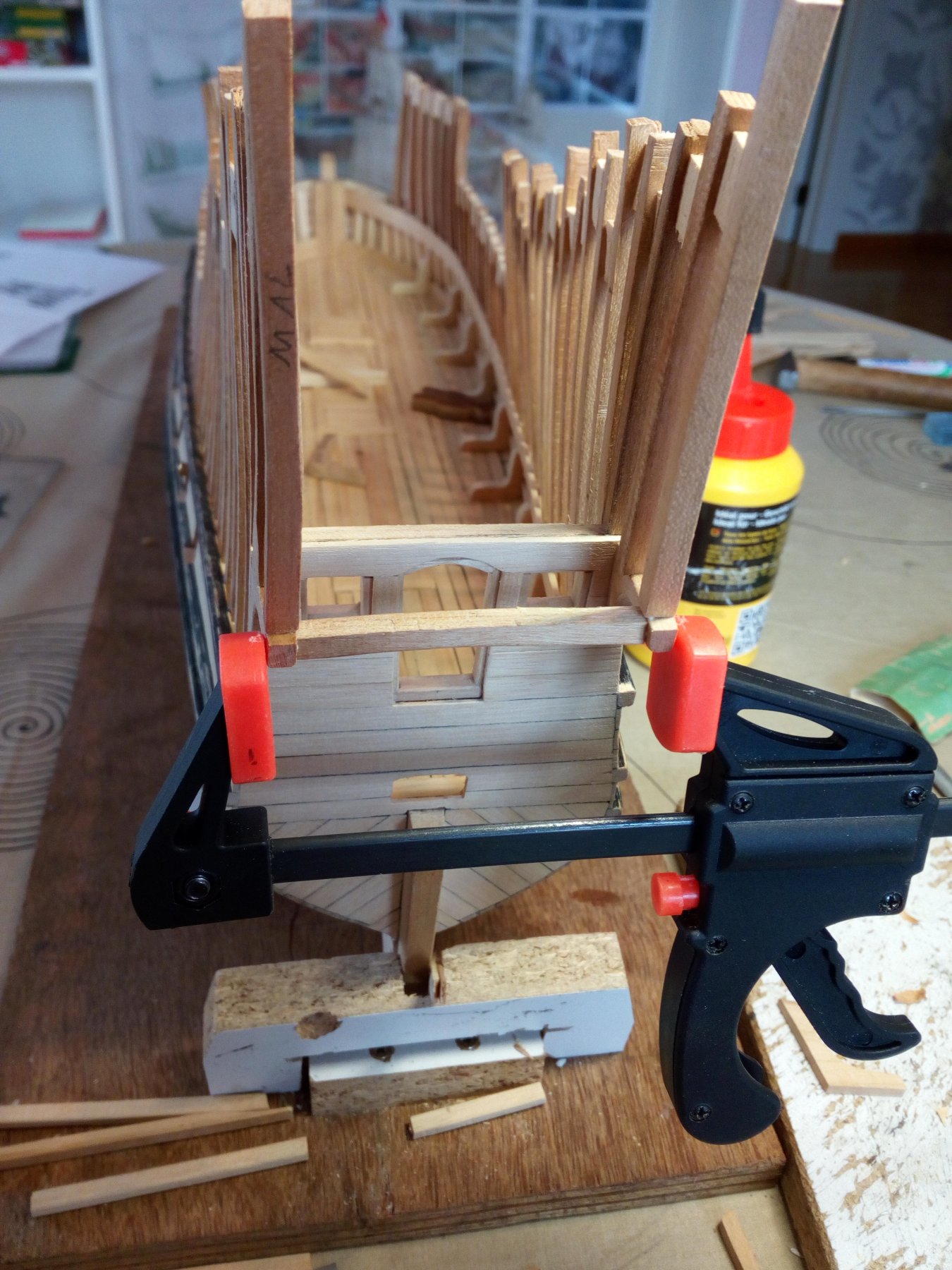
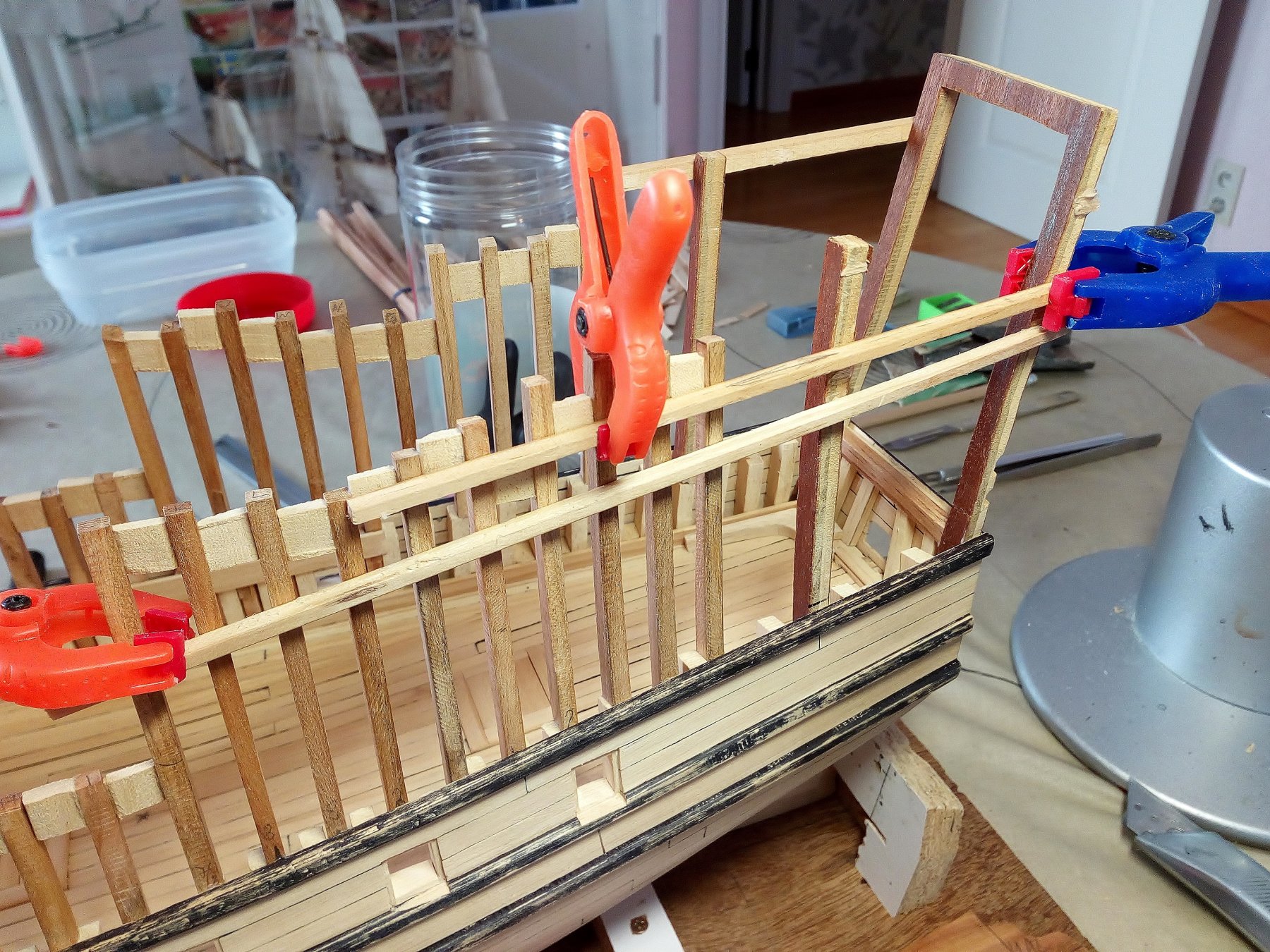
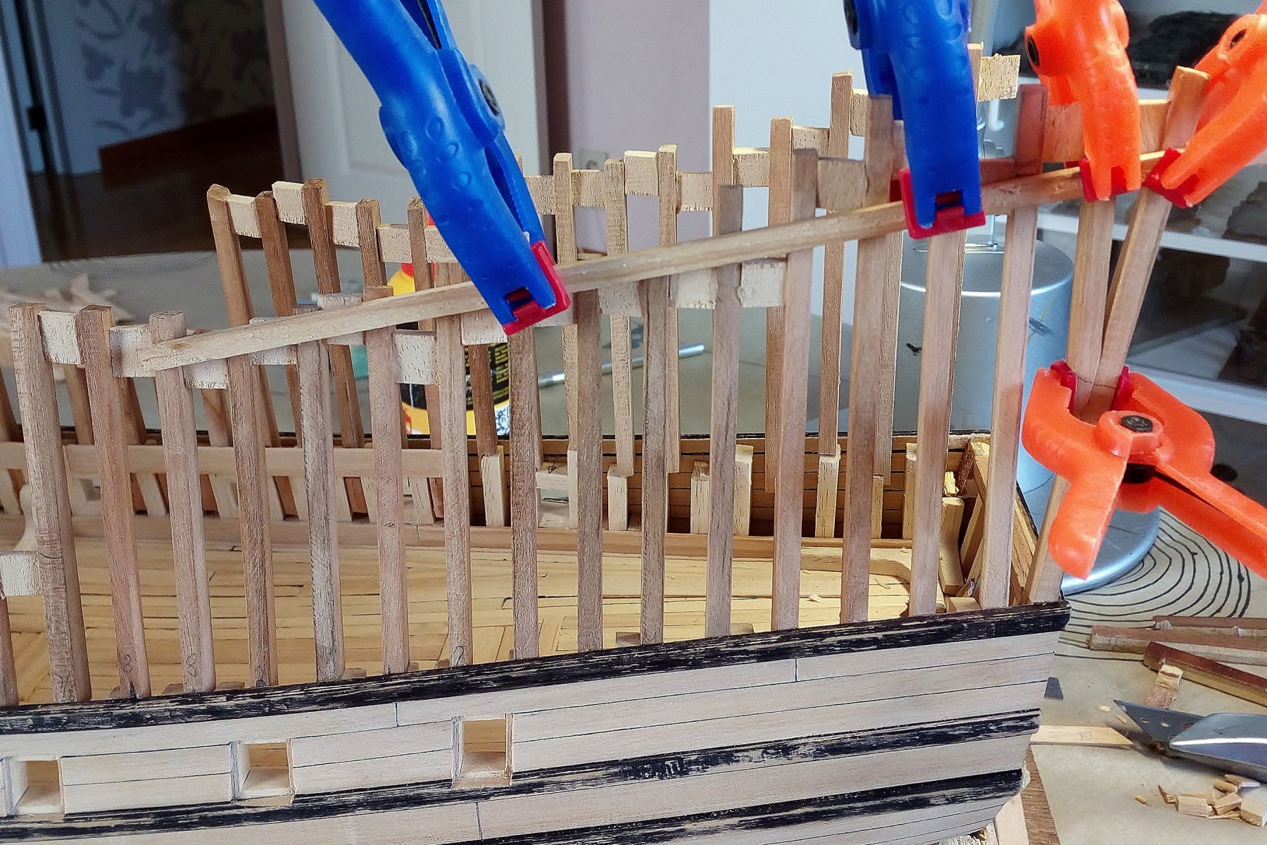
The plywood frames are replaced with frames of solid cherry wood. After long thinking I took 9mm as a space between the frames. It seems that the distance between 2 frames could have been between 38 and 45 cm (on scale 1/45 = 9 to 10 mm). This can match the width of the gun ports (40 cm) (10mm on scale 1/45) I made a mistake : I should have replaced the plywood frames first before start planking the upper hull. Now I have a few frames that are in the middle of a cannon port. I did not find any way to avoid this I hope that this is no longer noticeable after the hull is fully planked. Frames are supported at the top with soft wooden spacers (later easily removable). All the frames are now too long ( Shortening them is easier than making them longer) An extension must still be provided to the transom for the poop deck. But before I can do this, I must first know where the other decks will match the transom. I think I choose for a balcony around the stern. Maybe it's wrong, maybe it's right. Who knows? Thanks for following this buildlog Index post 1


.thumb.jpg.348646e8b97c7ba2e9ca8dbffb52b92f.jpg)
- 756 replies
-
- 15
-
-
- galleon
- golden hind
- (and 2 more)
-
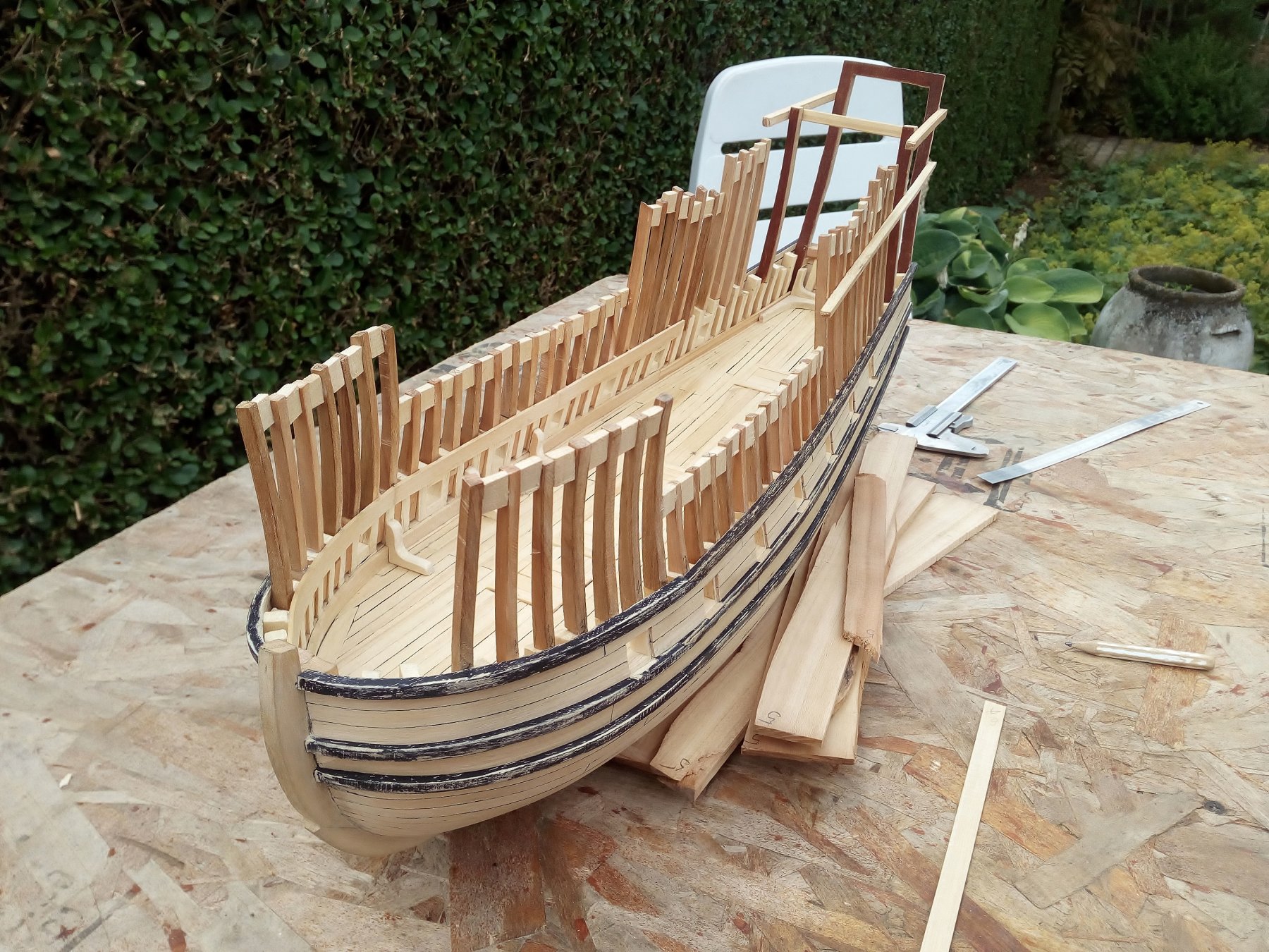
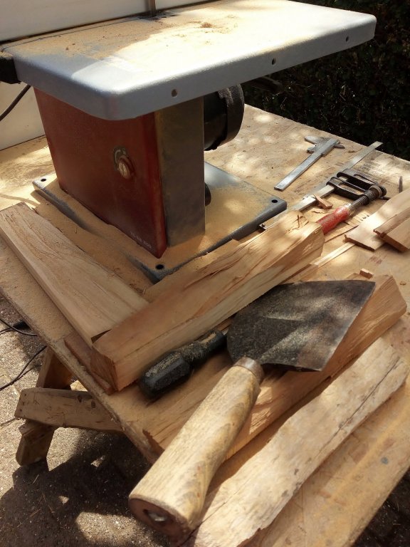
Thank you Lawrence. Scratchbuilding a wooden ship is something totally new to me. Before I started this, I had no idea of the complex structure of the interior of a wooden ship. I have learned a lot of shipbuilding in the 16th century. If all of the information I found is helpful to others. glad to be of service. Meanwhile, construction continues. Saw cherry wood (With old-fashioned and with modern tools) Replace the plywood frames (work in progress). I hope to do an update soon And everyone Thank you for following this log Index post 1

- 756 replies
-
- 12
-
-
- galleon
- golden hind
- (and 2 more)
-
First i agree with juhu For me about sailing ships Plastic model sailingships or wood model sailingships are a world of difference. The (current) plastic kits are relatively "cheap" and well-detailed. And yes, (again) many of these kits come from China or other low cost countries. To me, some makers of wooden model ships still seem to be somewhere in the 70s or 80s (NOT all of theme). But these models are still being built by companies that have to make a profit. Building a wooden model of a ship. Is for many builders a dream that takes too long and never reaches the end. A combination of wood and plastic or resine would be ideal. Comment on your question : Nobody says you can not do a combination of the 2 yourself. Plastic model builders sometimes mix models from different manufacturers. And then use only the best pieces. Expensive But those choices are to be made. To start, building a wooden model ship is expensive in purchase. But considering the amount of hours spent on building a wooden model. It is relatively cheap hobby.
-
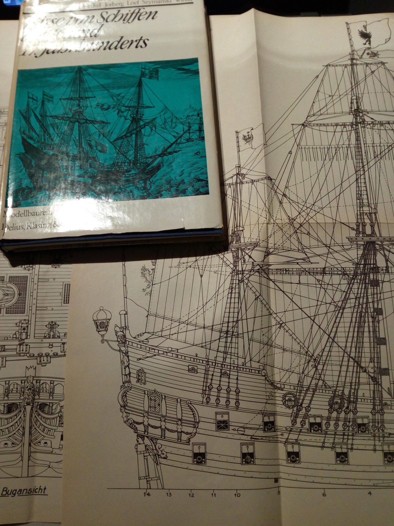
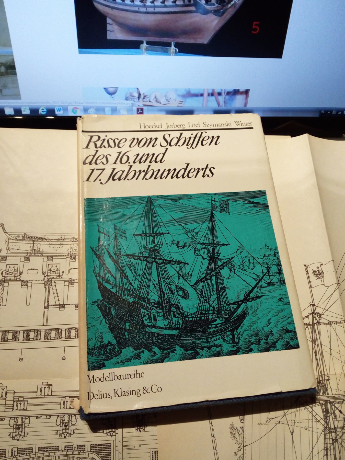
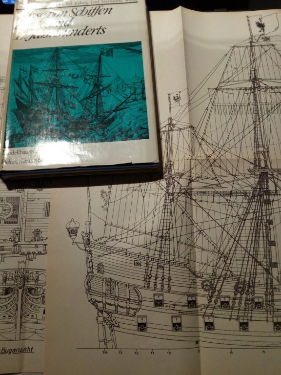
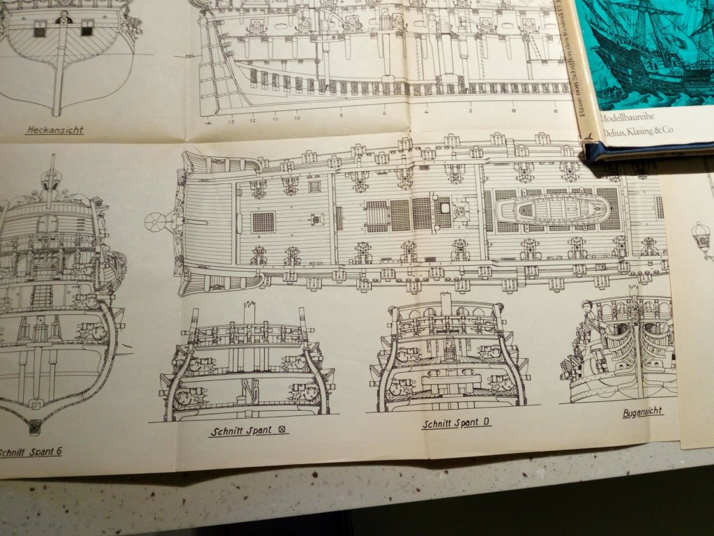
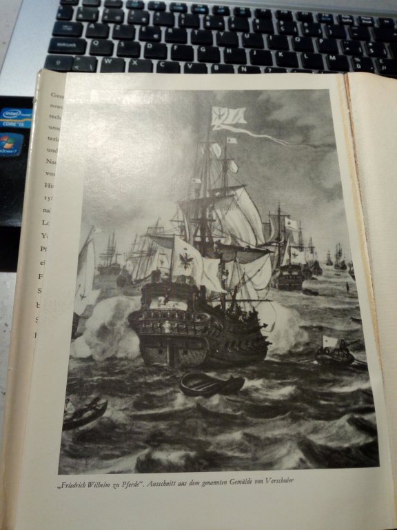
I found these plans of the Wilhelm in "Risse von Schiffen des 16.und 17. jahrhunderts." There is also no explanation in the text about this. There is also a picture of a painting. Perhaps the former painter made a mistake. And the designers of the drawings simply took over them

-
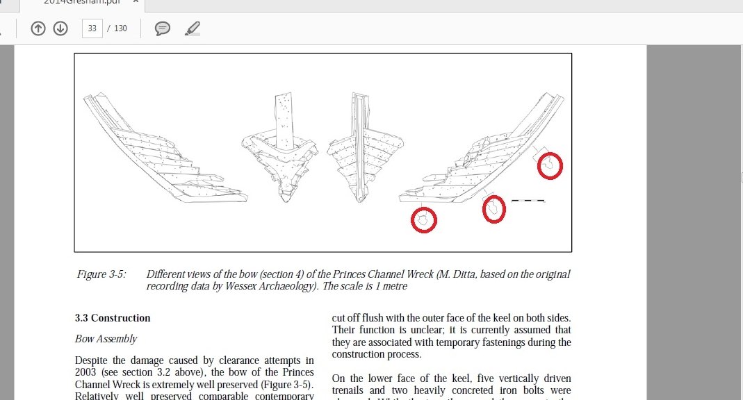
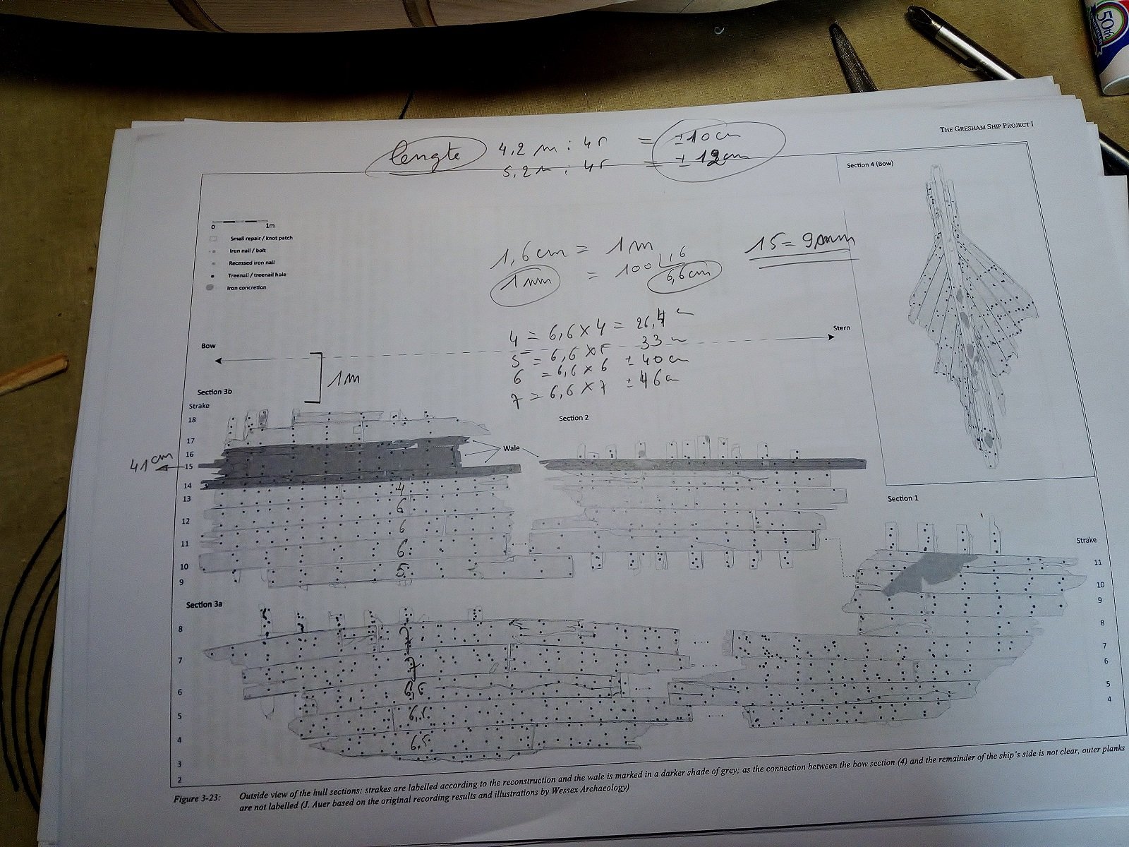
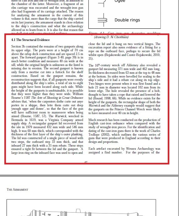
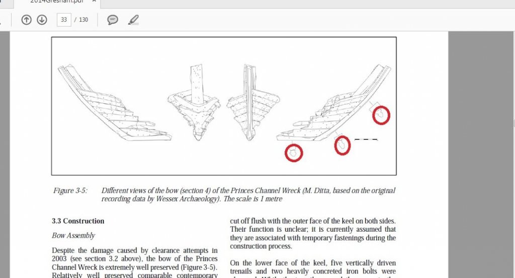
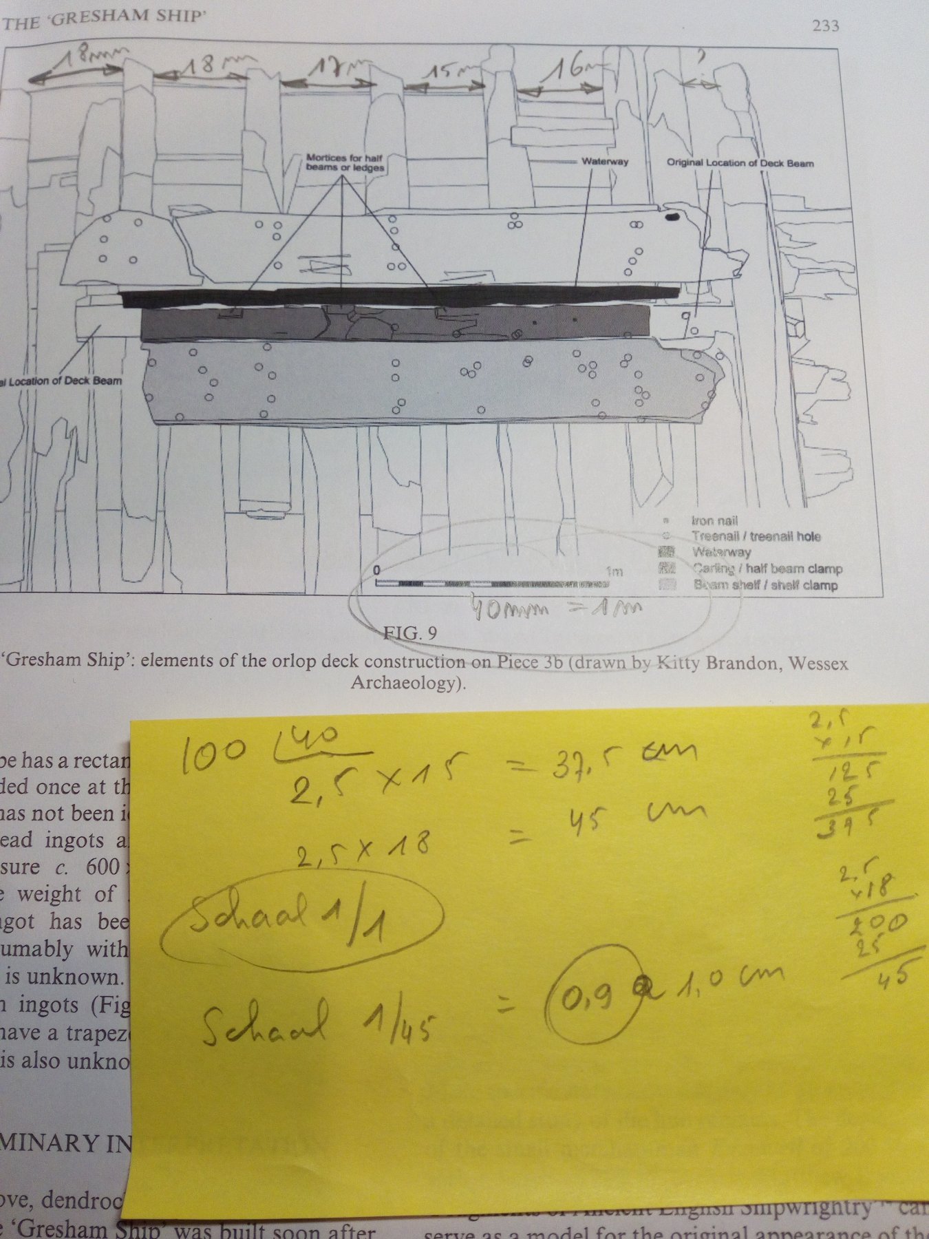
On my model The space between the waterline and the underside of the cannon port = 90 cm The space between deck and the underside of the cannon port = 70 cm So the cannon deck = 20 cm above the waterline Different sources all say that the height of the deck was about 160 cm (interior) At the end of last year I had some free time to do some calculations The buildlog about the "cannon breech rope length" Is very interesting (thanks Mark).. I came for the master frame on my Golden Hind at this result. 2014Gresham.pdf
-
I agree with Chuck. 24 pounders are far too big for such a small ship. But if you really want to place these 24 pounders. Please put them under the upper deck. Otherwise you have an unstable ship (See my Golden Hind build log)
-
Looks good. Your model looks similar to what I want to build in wood. The transom may be too low below the water line.
-
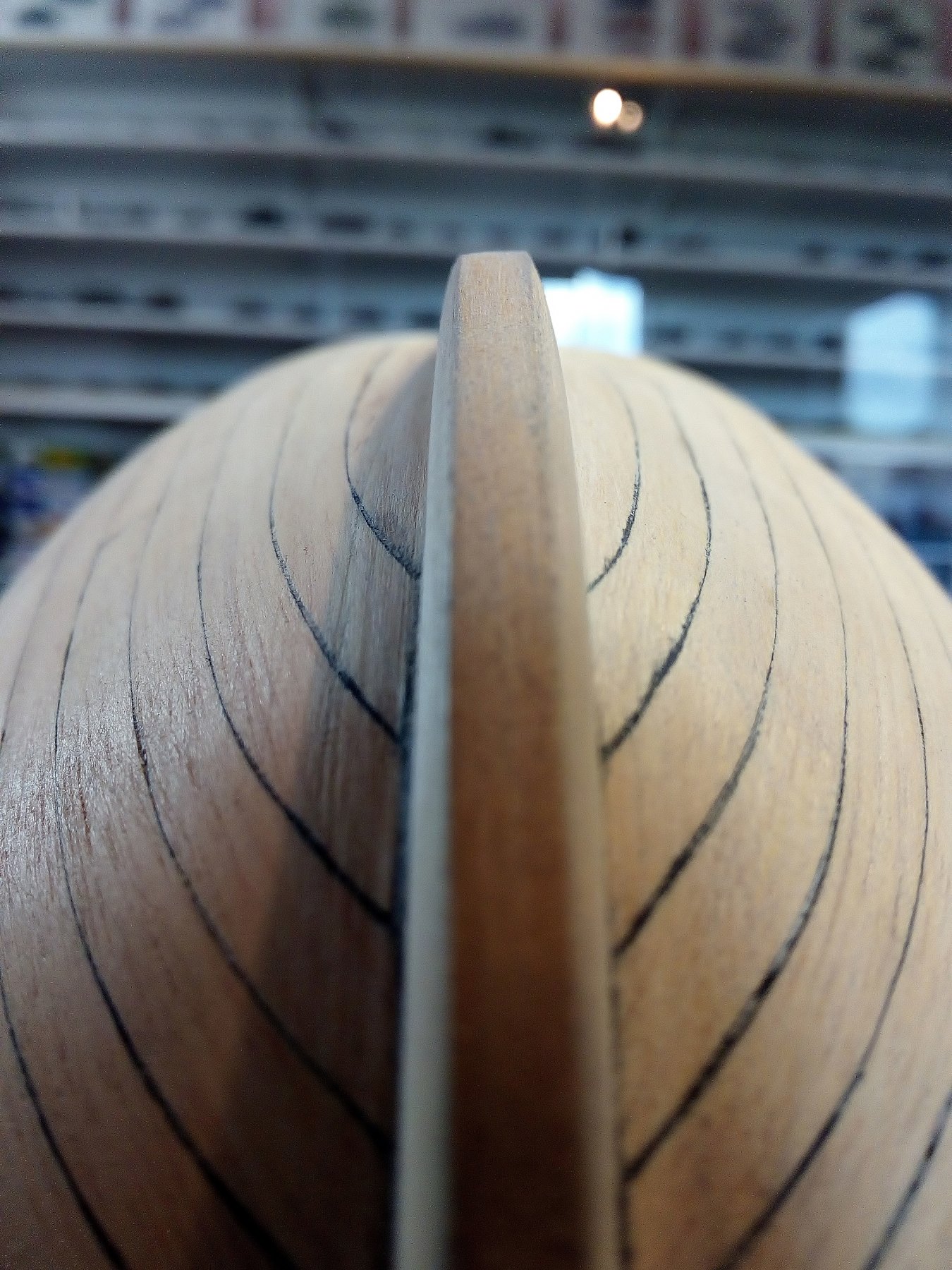
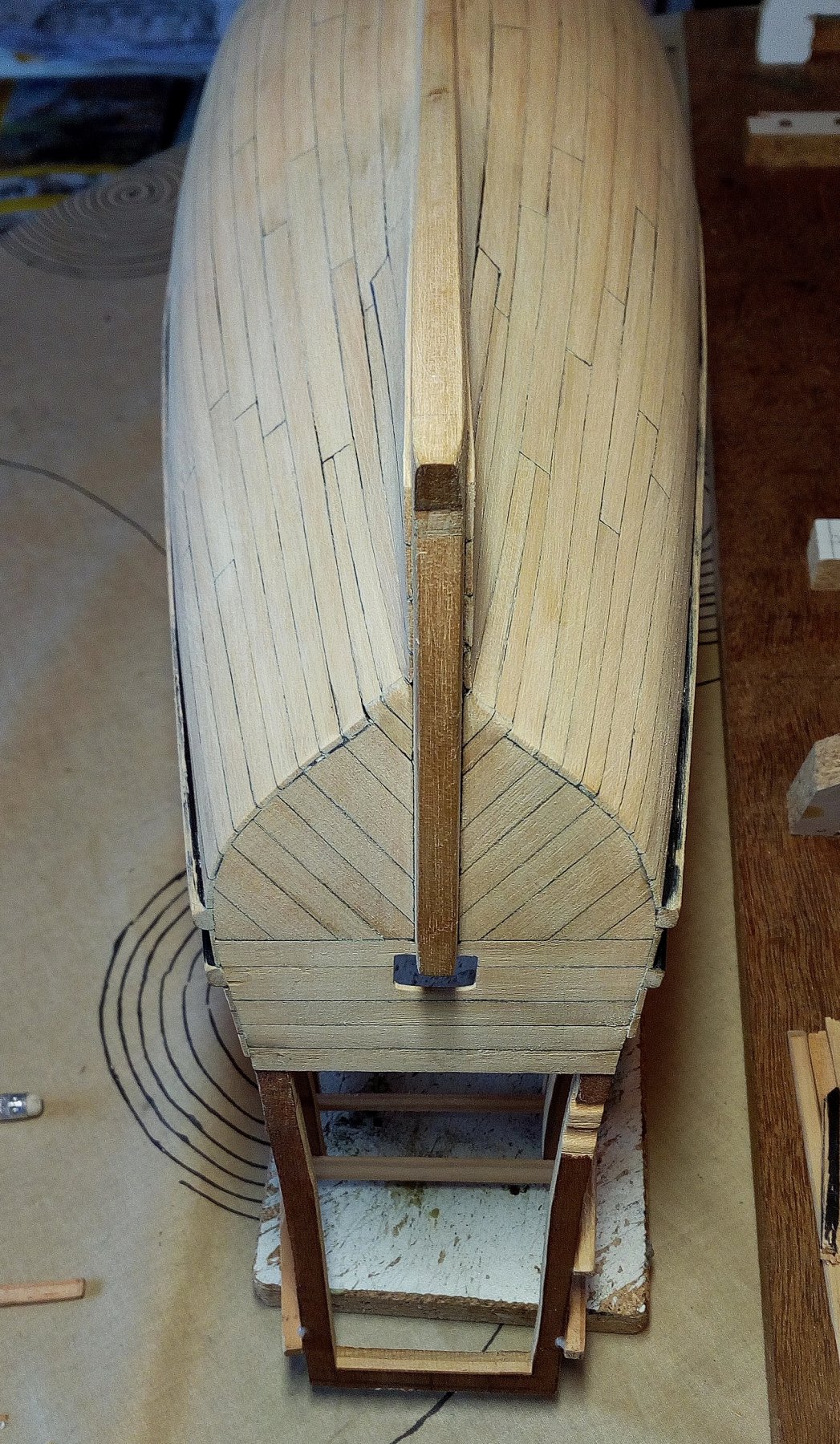
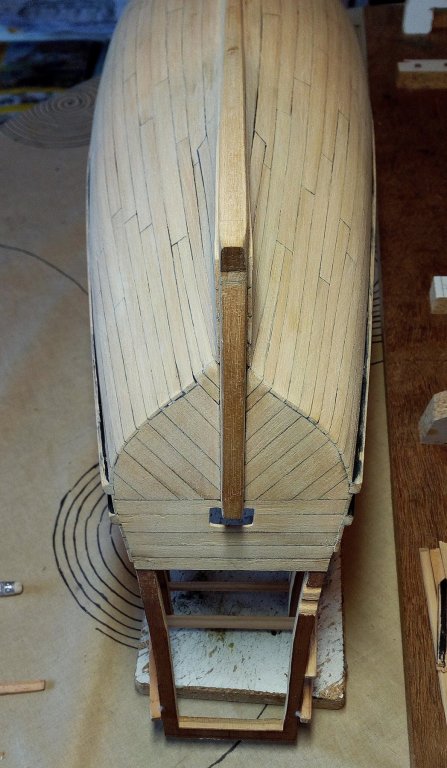
The stempost and the forward part of the keel is made a little tapered. The tapered part stops between the main mast and the stern Source : The Gresham ship project Index


- 756 replies
-
- 17
-
-
- galleon
- golden hind
- (and 2 more)
-
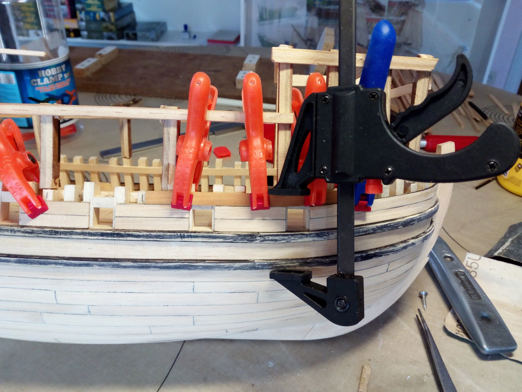
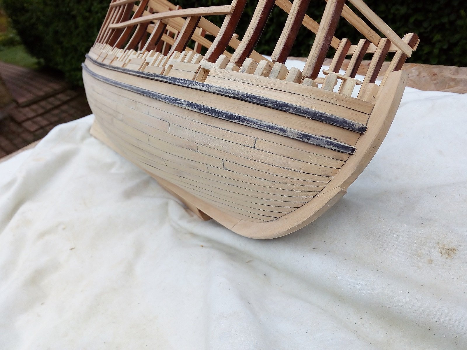
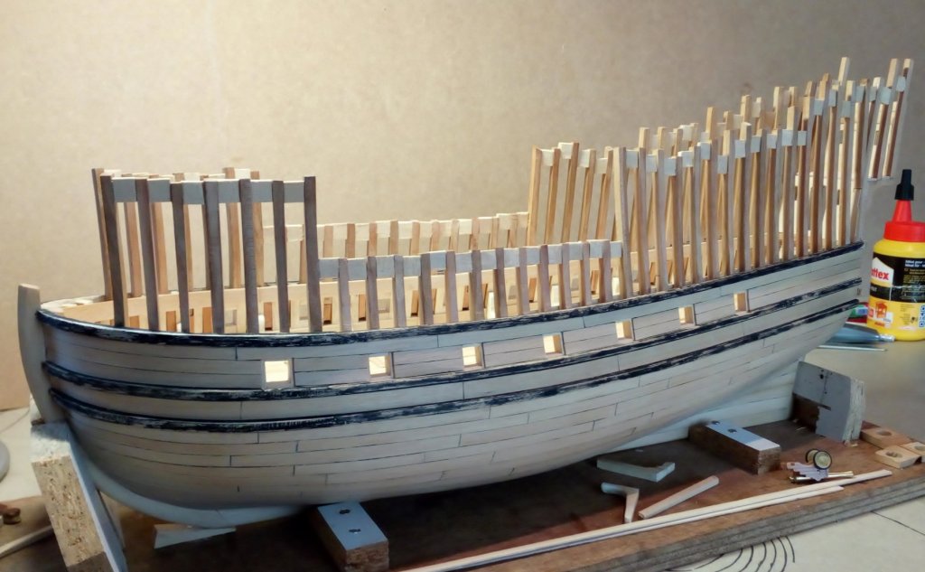
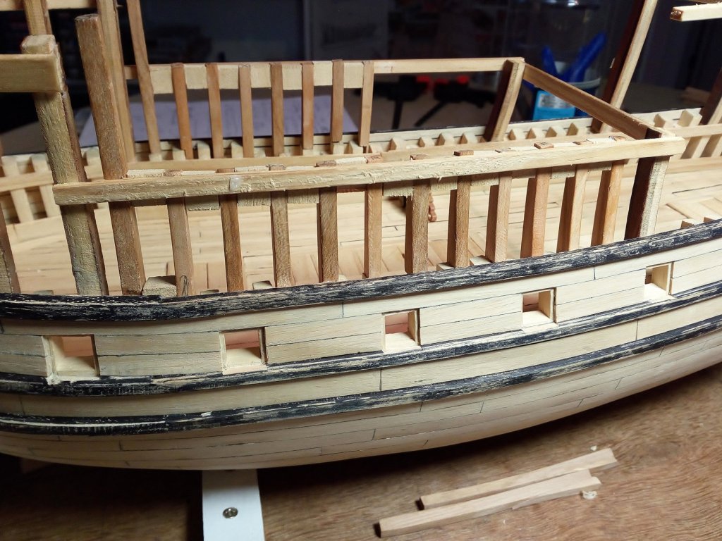
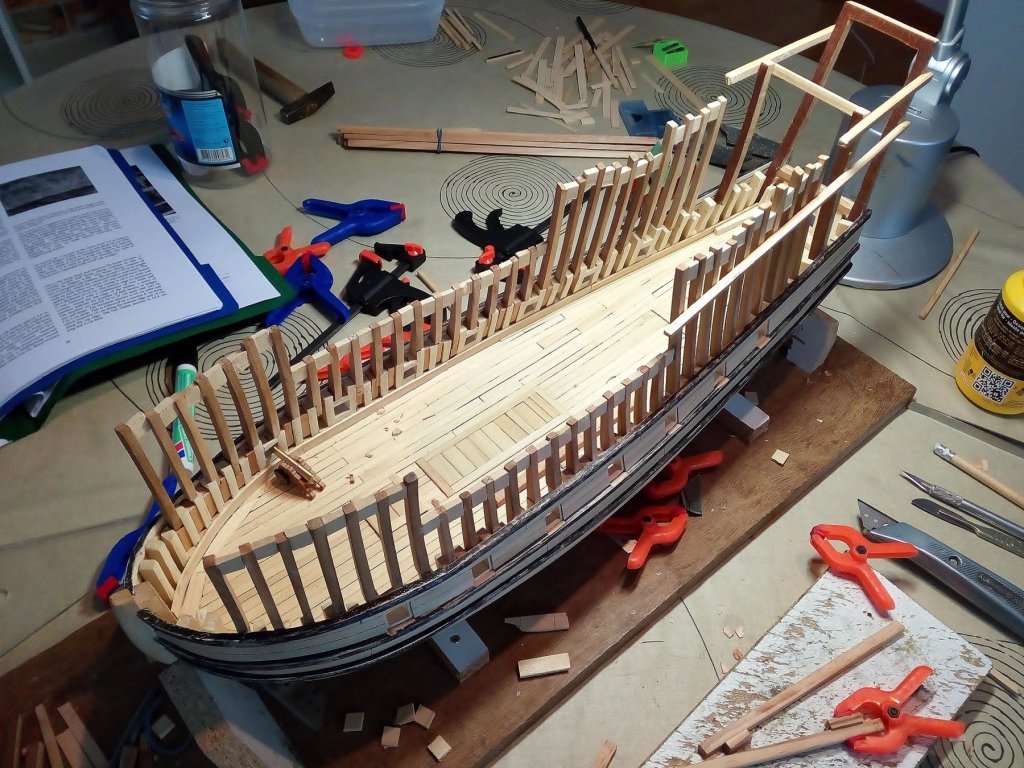
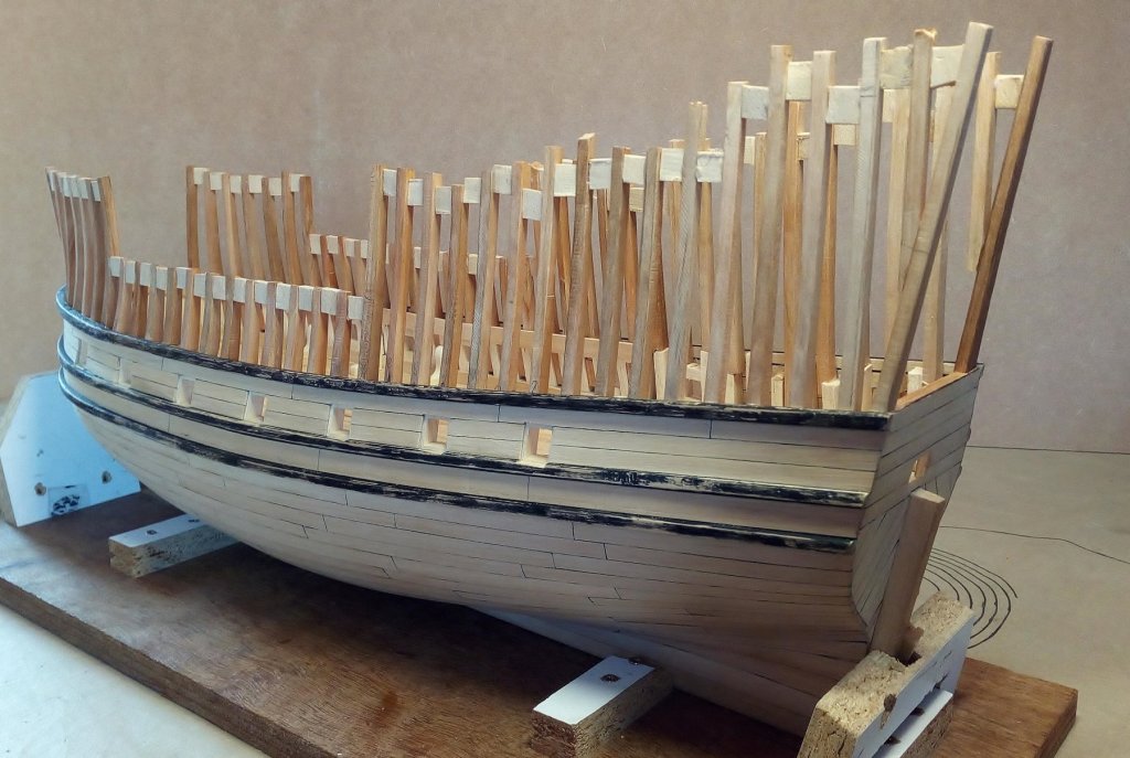
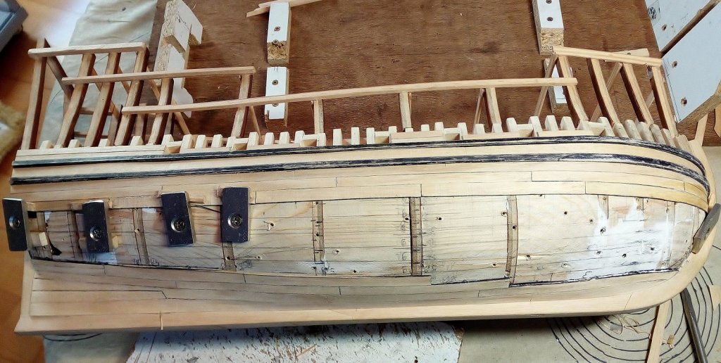
Hallo, The cannon deck is planked. And the upper wale is placed. Width of the gun ports is 9 to 10mm (40 to 45 cm on a real ship) Source: Gresham Ship Project. Index


- 756 replies
-
- 16
-
-
- galleon
- golden hind
- (and 2 more)
-
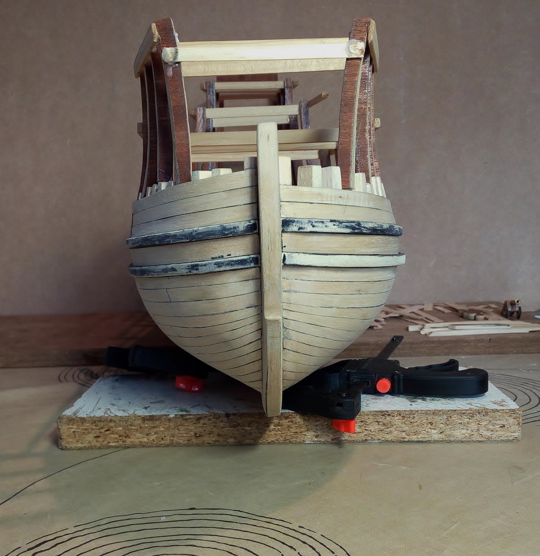
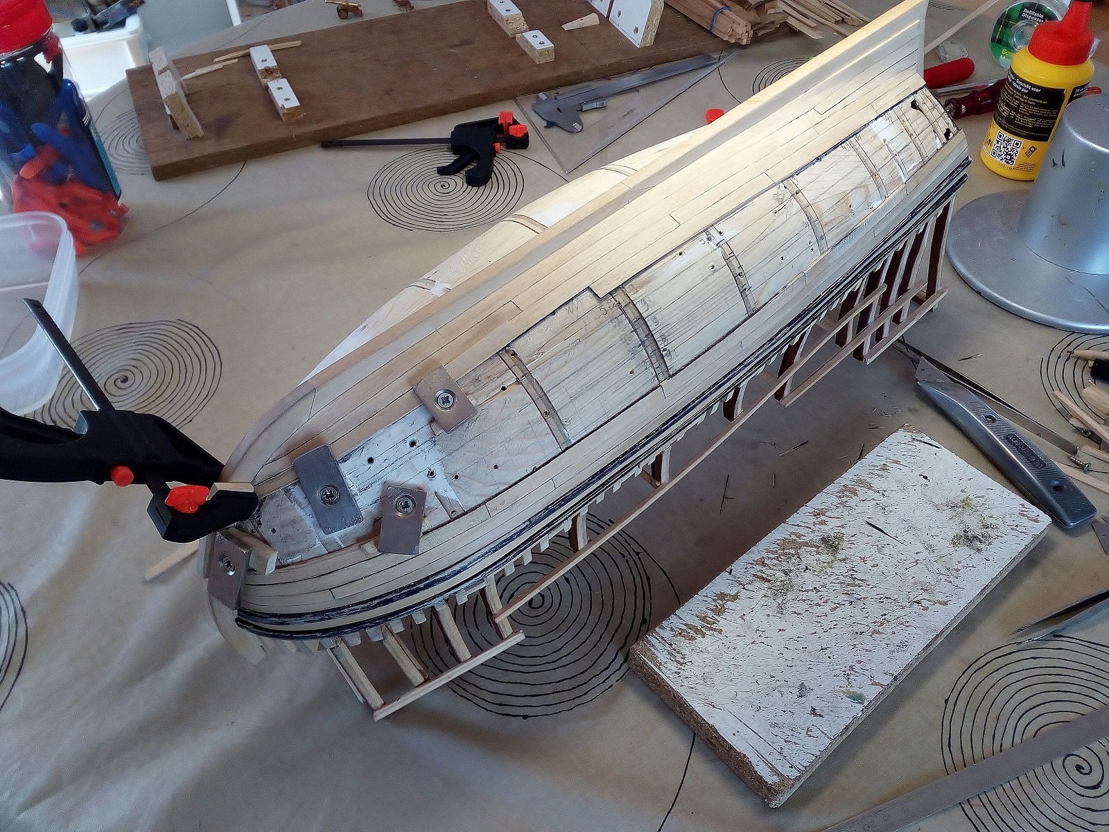
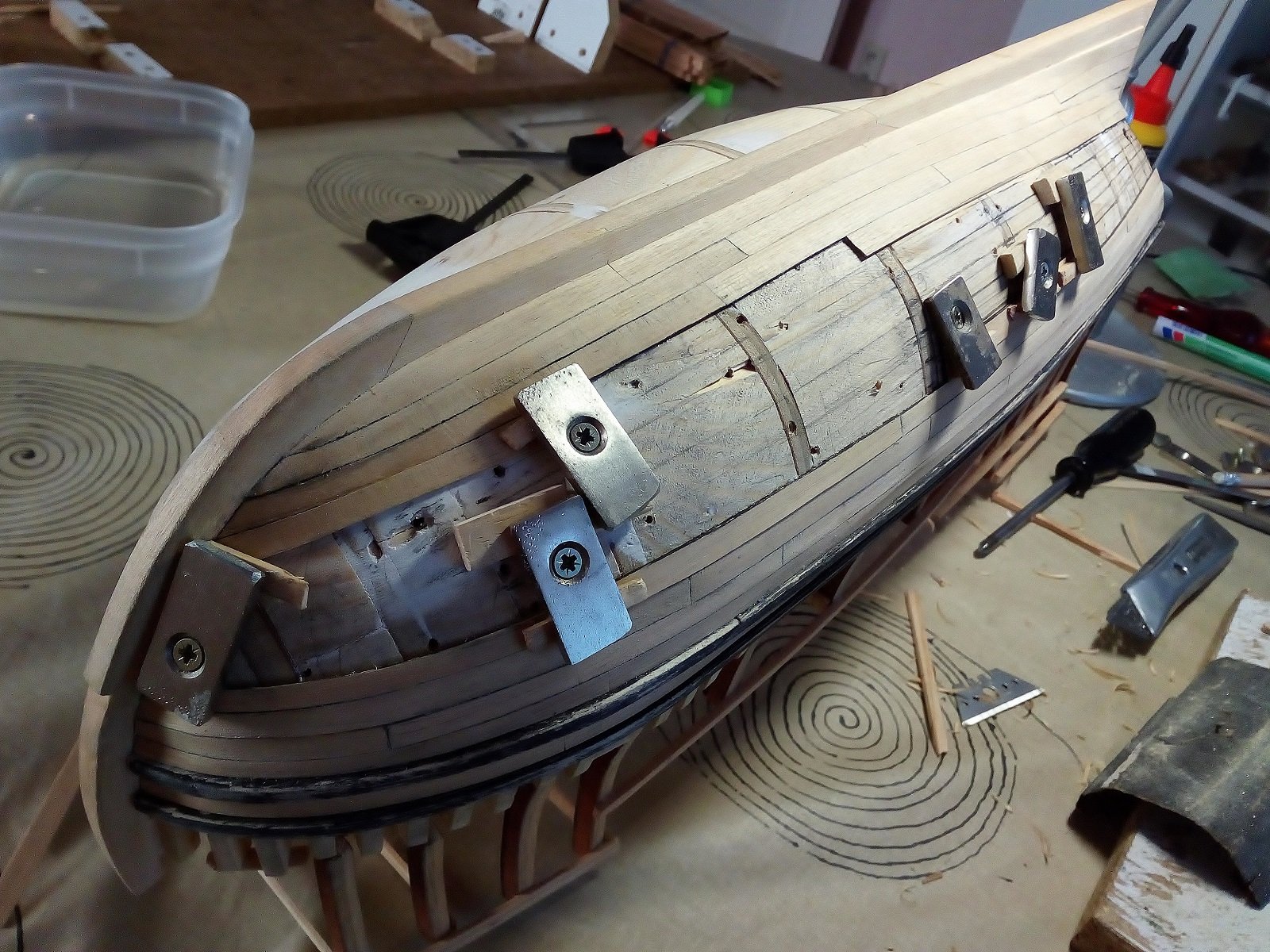
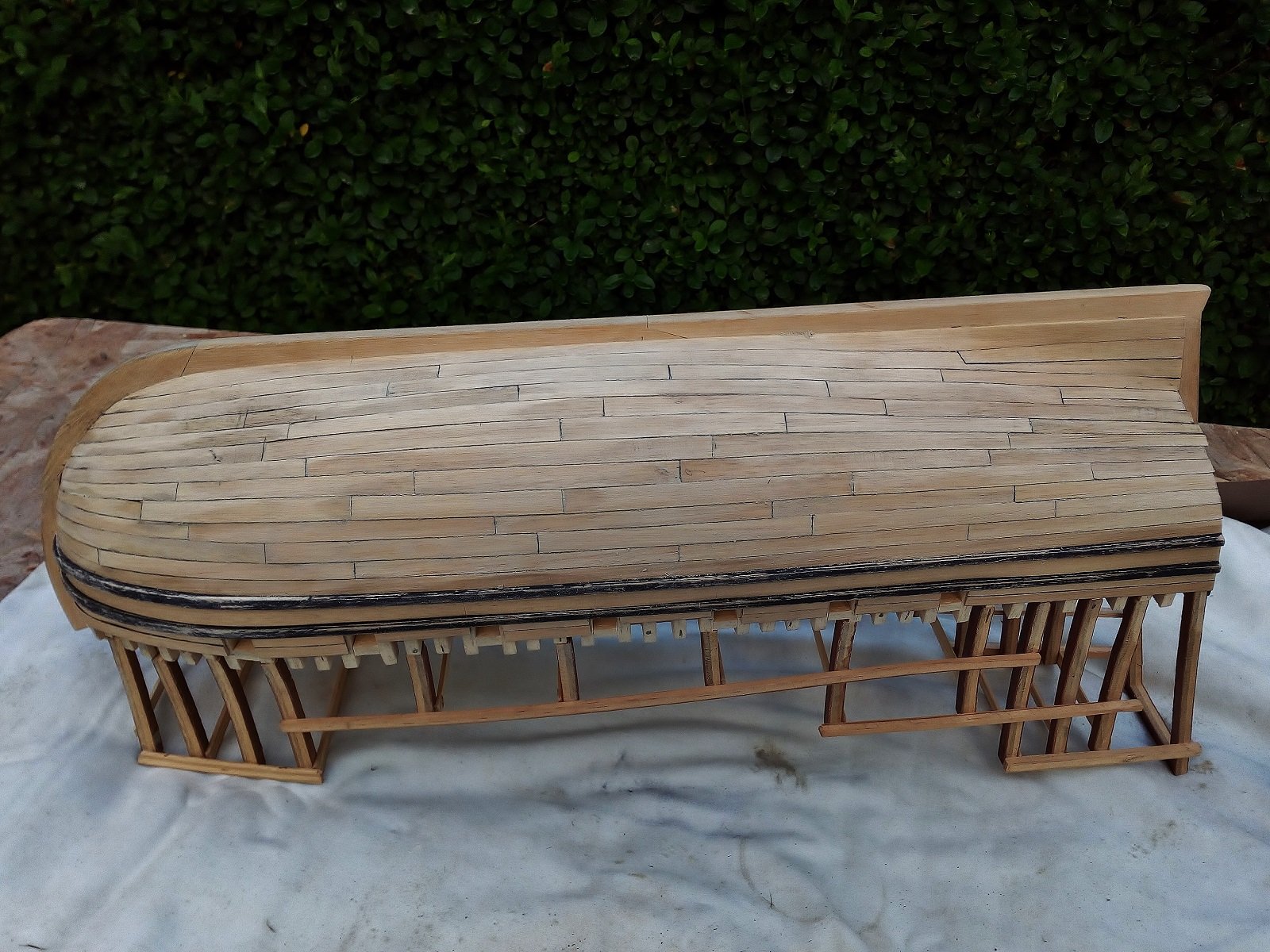
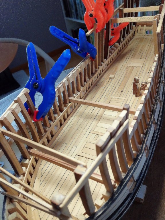
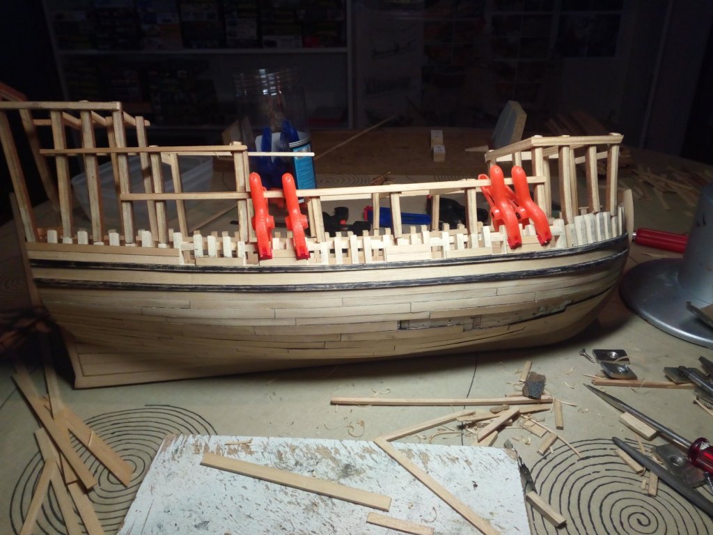
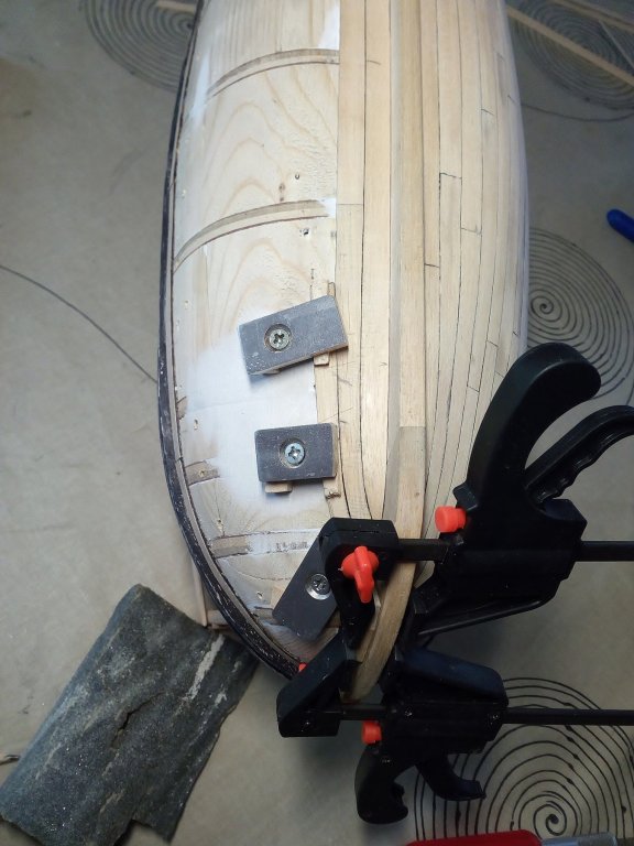
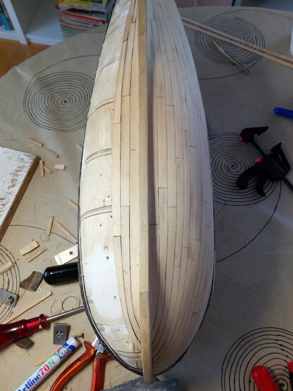
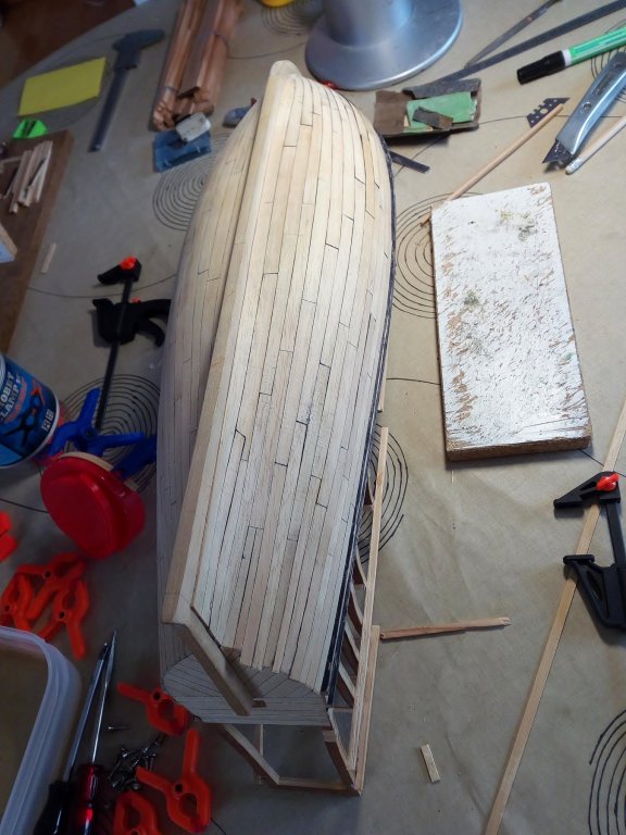
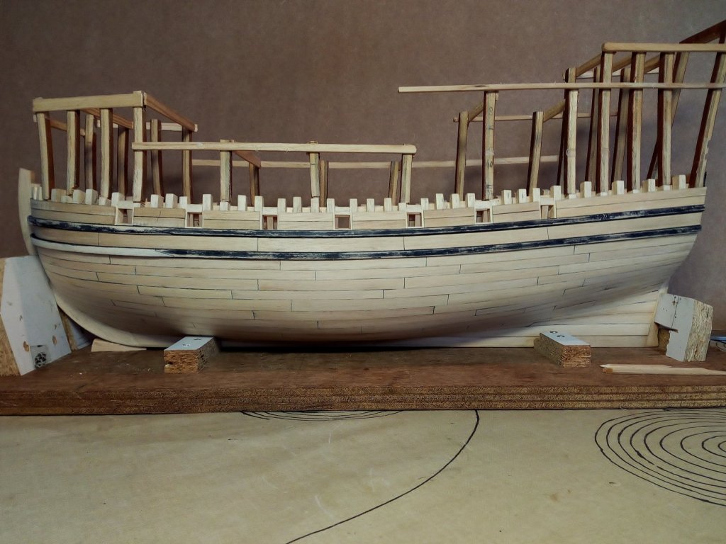
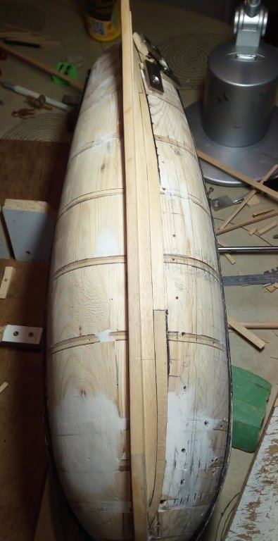
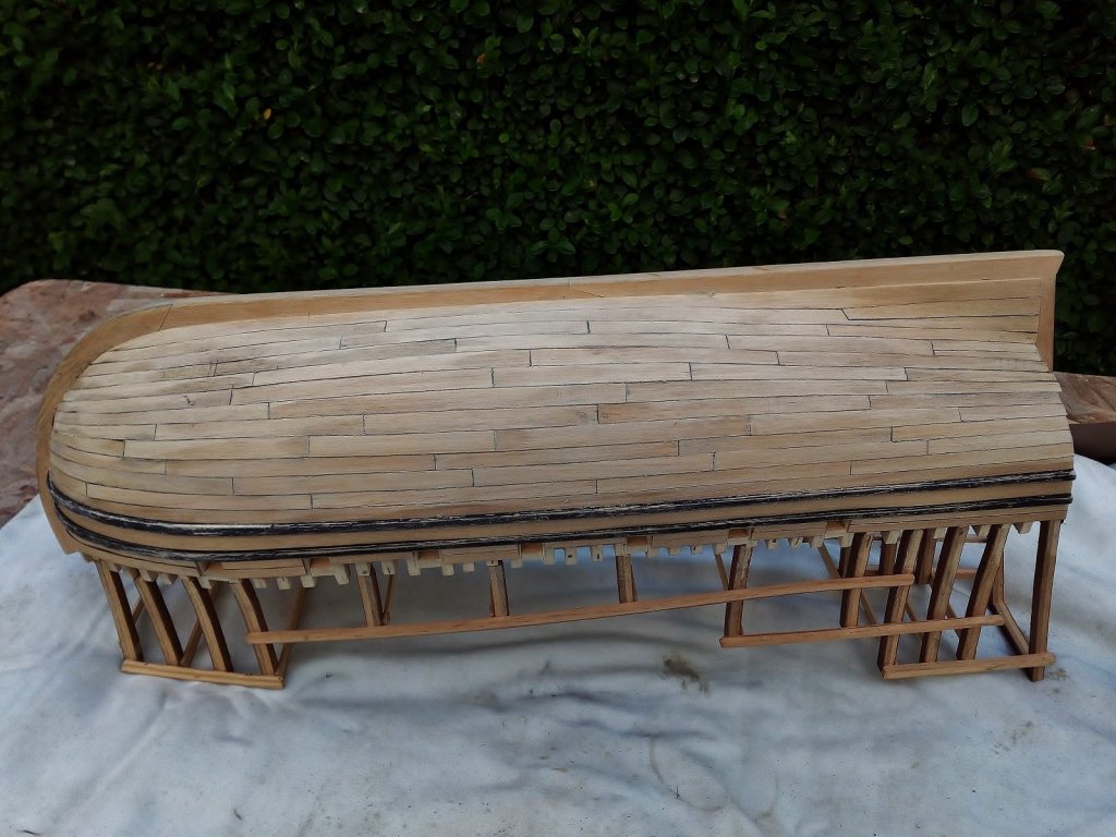
Small update : Planking the lower part of the hull (part two). The entire lower part of the hull is planked. Planking has been done using the same method as in Part 1. Planking on the gun deck is started but not yet ready. Next to do : Further planking on the gun deck. Further sanding the hull. Make the forward part of the keel and the stempost a little taper. Make frames to the upper decks in cherry wood Etc……… Index in post 1


- 756 replies
-
- 17
-
-
- galleon
- golden hind
- (and 2 more)
-
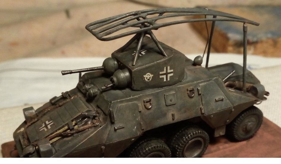
The length of a gun barrel does matter. An "modern" example is a russian WW 2 small anti tank kanon. The 45mm model 1937 modernised in 1942 to the model 1942 by making the barrel longer. A longer barrel and higher load of pouwder gives a higher muzzle velocity. This gives a longer range and a more flat trajectory to a projectile that has same weight. https://en.wikipedia.org/wiki/45_mm_anti-tank_gun_M1937_(53-K) Muzzle velocity 760 m/s (2,493 ft/s) https://en.wikipedia.org/wiki/45_mm_anti-tank_gun_M1942_(M-42) Muzzle velocity 870 m/s (2,854 ft/s) So these long cannons on the upper deck could be used to hit an object at a longer distance. The gun crew could " safely " lean out over the bulwarks to clean and reload them offboard as they were still away from the enemy I hope my explanation in "google english" Is understandable. And i may be completely wrong with this theory. But this is the thinking of a military modeler. Who has more experience with anti tank guns than with 17th century shipcannons.
-
Michael, Thank you for the explanation and photos. These holes are at such a vertical angle that they are indeed more suitable for cannons instead of seats of ease.
-
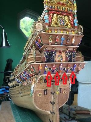
Michael There is something I'm curious about. Somewhere I've read that the four round holes in the transom served as seats of ease. But on your model there are four cannons through these holes. Went looking in your buildlog And found this (old) photo from the transom ( i think page 30)
-
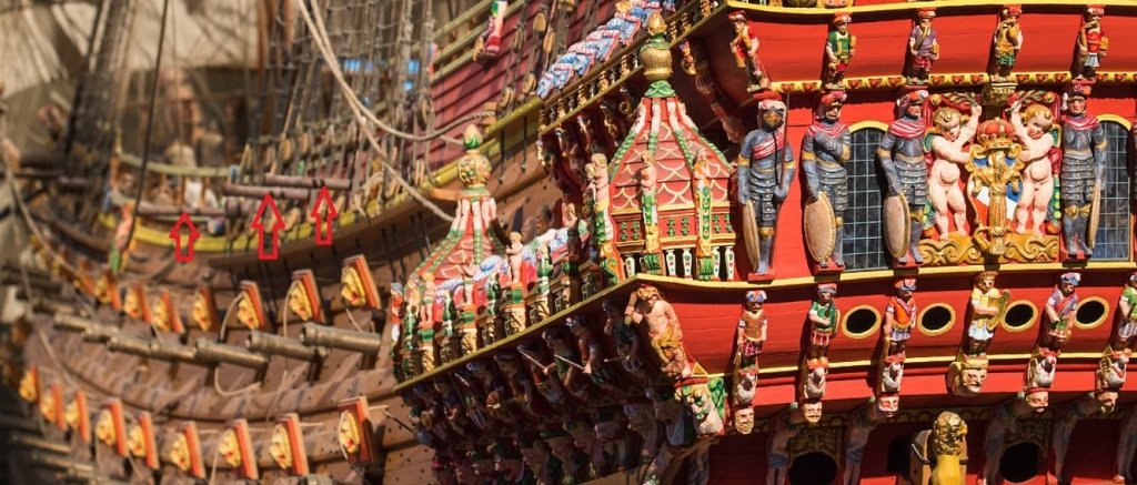
Great rigging Michael. And about the lack of space for the cannons on the upper deck. On the 1/10 model in the museum the long cannons are now placed on deck. How could they ever load these cannons? Picture is from the www.Vasamuseet
-
thanks Chris and Christian My way of construction is indeed not as seen in most buildlogs. And it takes a bit longer. The ultimate goal is to build a model as realistic as possible.
- 756 replies
-
- 4
-
-
- galleon
- golden hind
- (and 2 more)
-
And thank you Zoltan. The book you advised me to buy will be very useful for the further construction of this model.
- 756 replies
-
- 1
-
-
- galleon
- golden hind
- (and 2 more)
-
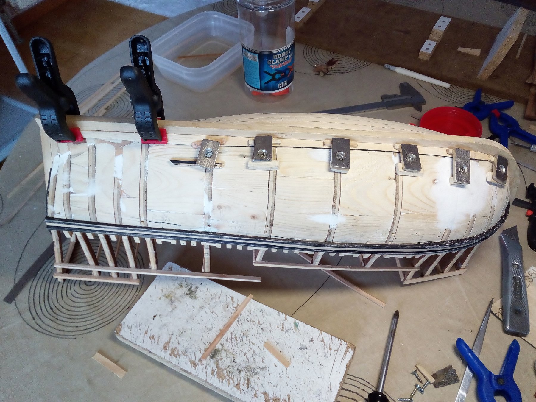
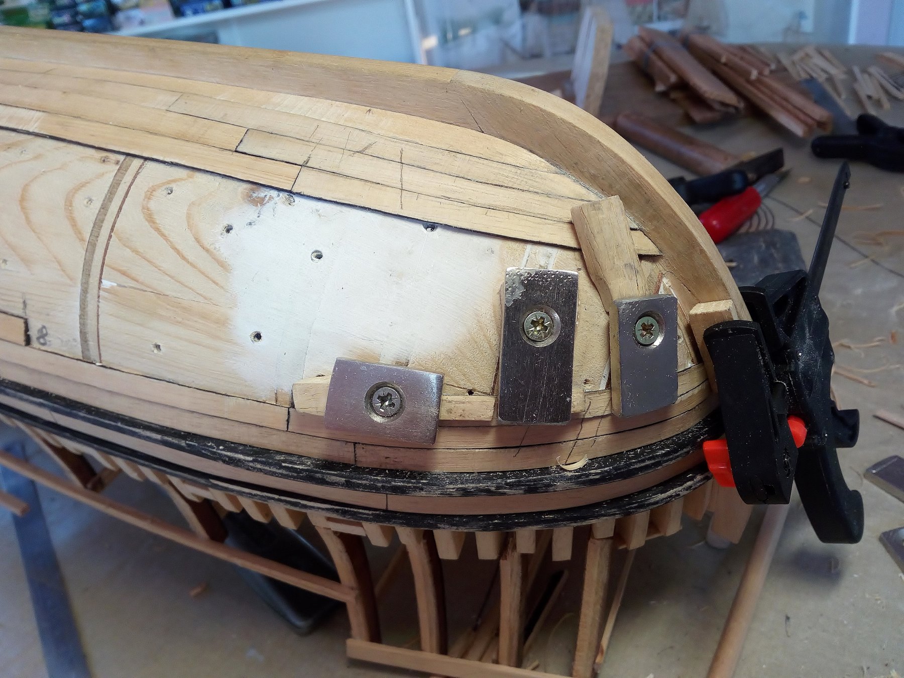
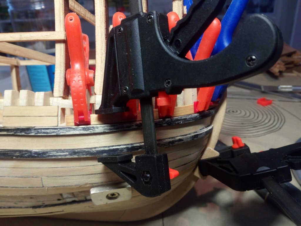
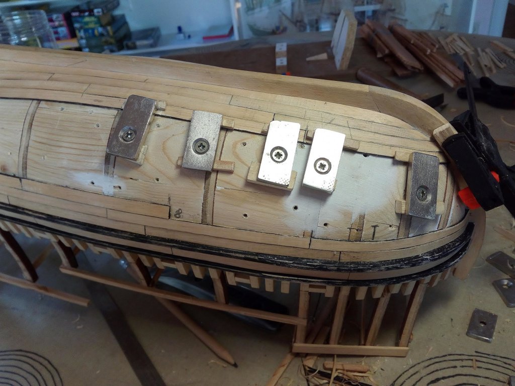
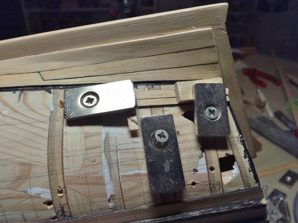
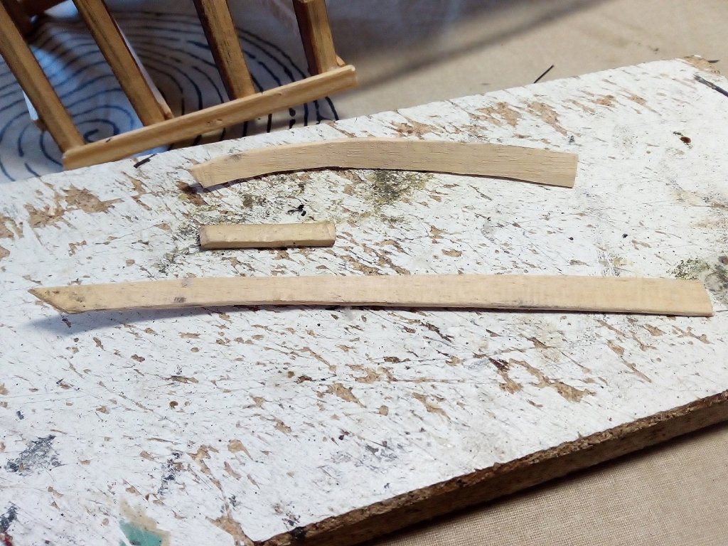
Thanks Michael, I'm glad to be in your memory files The combination of plywood frames and filler blocks indeed gives a solid hull I remember the problems I had with my Vasa planking where I only had frames and no experience in planking... It was then that I said. Grrr... planking a wooden hull Never again For me, on the lower part of the hull, it takes the same amount of time to place filler blocks instead of a first planking. And filler blocks are in my opinion better. Errors can easily be sanded. And you have a solid basis to bend the planks. Make plank in the right shape. Soak them well in water Clamp them onto the hull and allow to dry Remove them, ad glue on the plank, clamp them on the hull and let dry. Finish The planks are always bent correctly and no expensive tools are required. Thanks to everyone for following and likes Index on page 1
- 756 replies
-
- 5
-
-
- galleon
- golden hind
- (and 2 more)
-
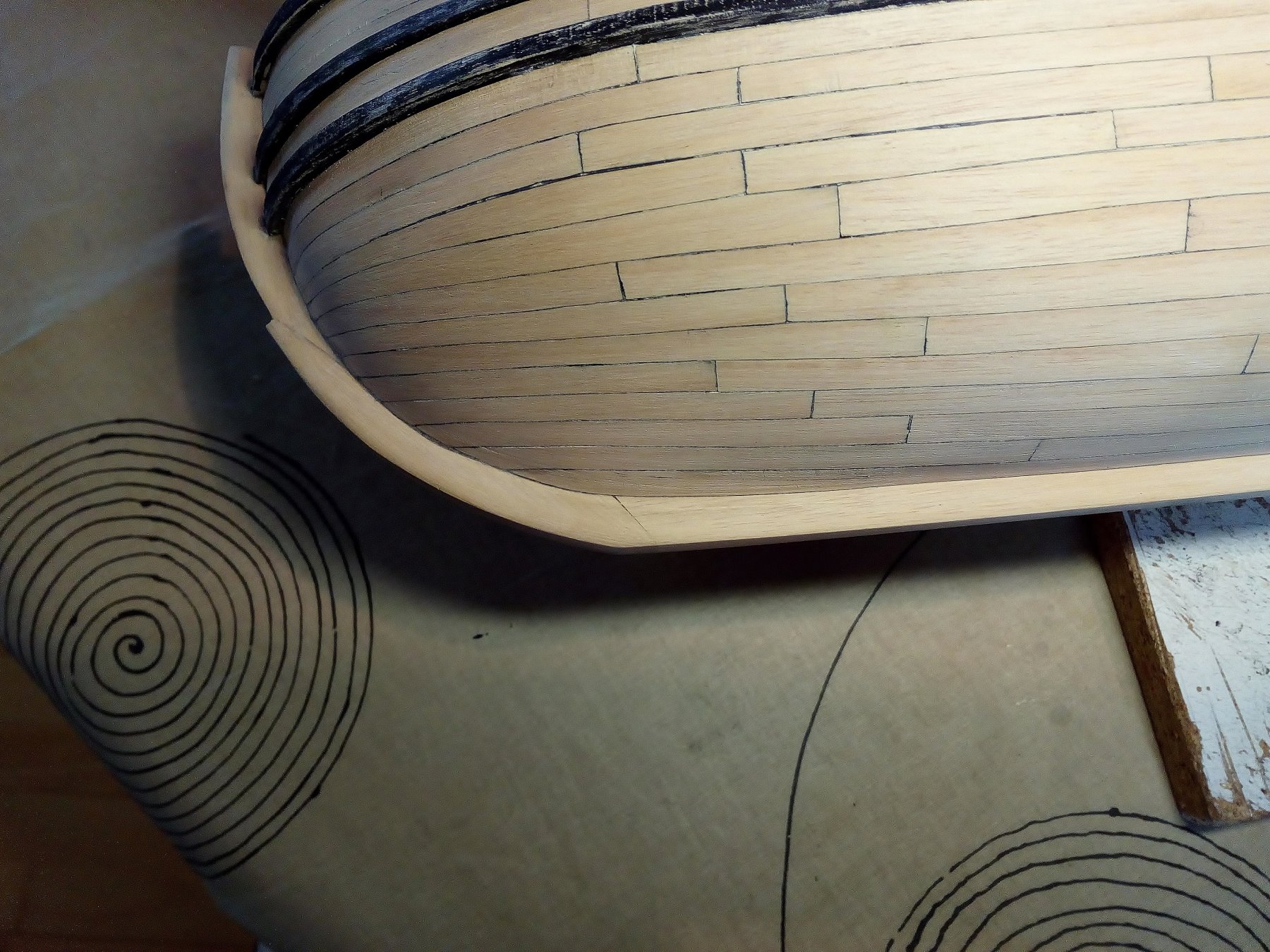
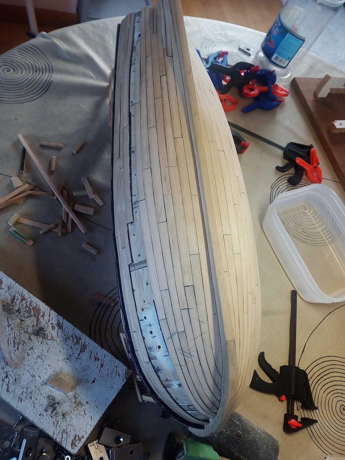
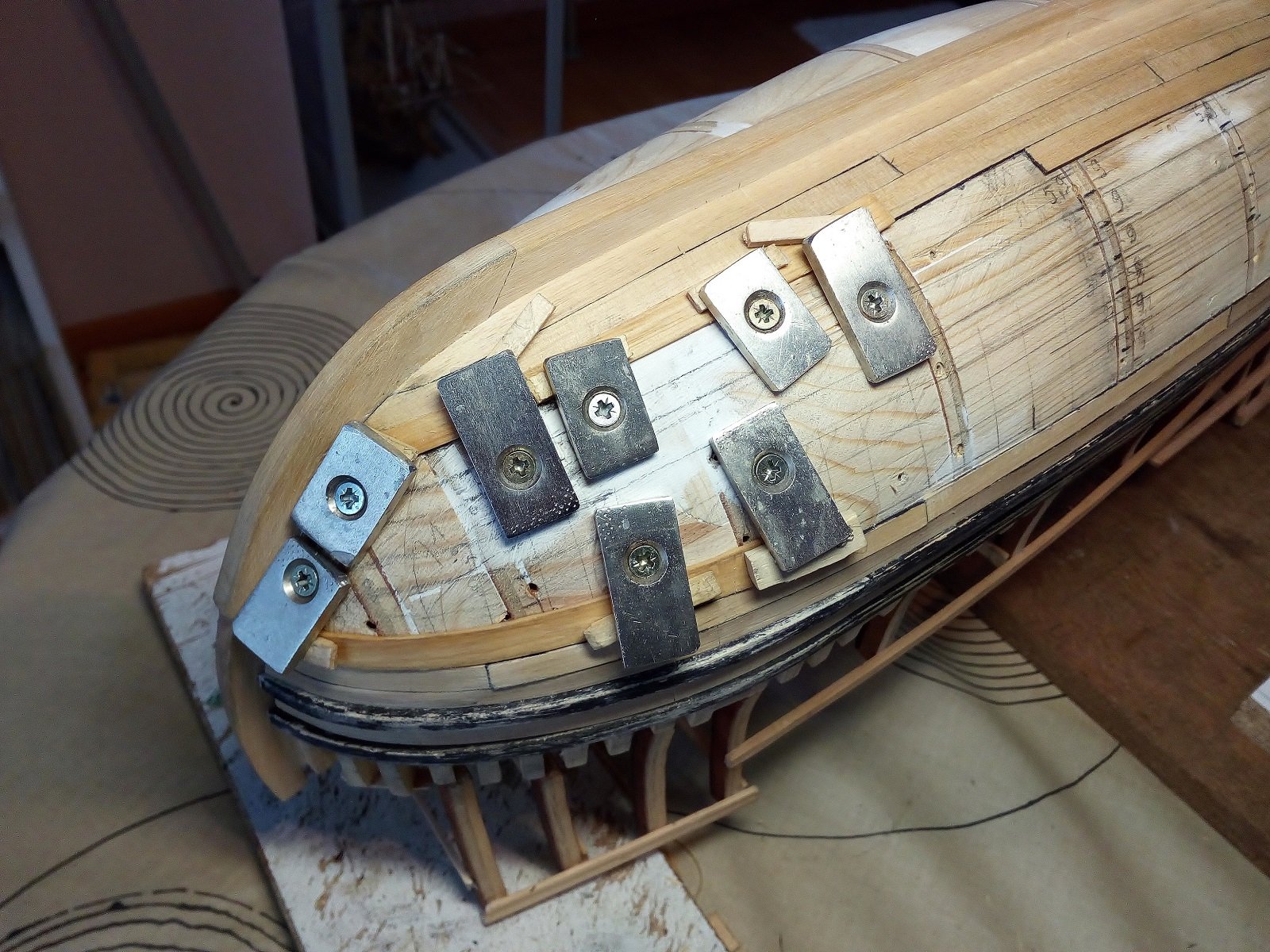
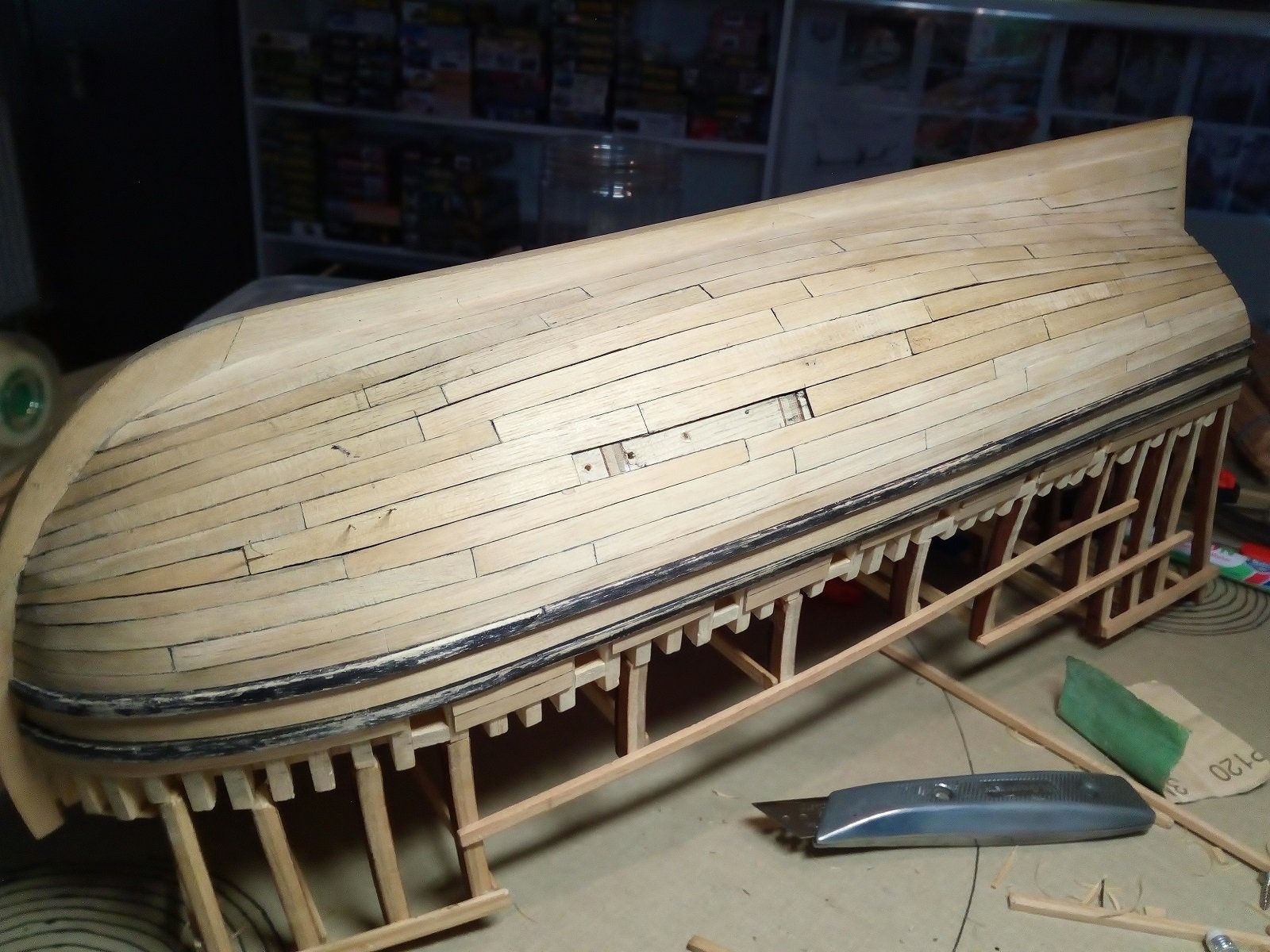
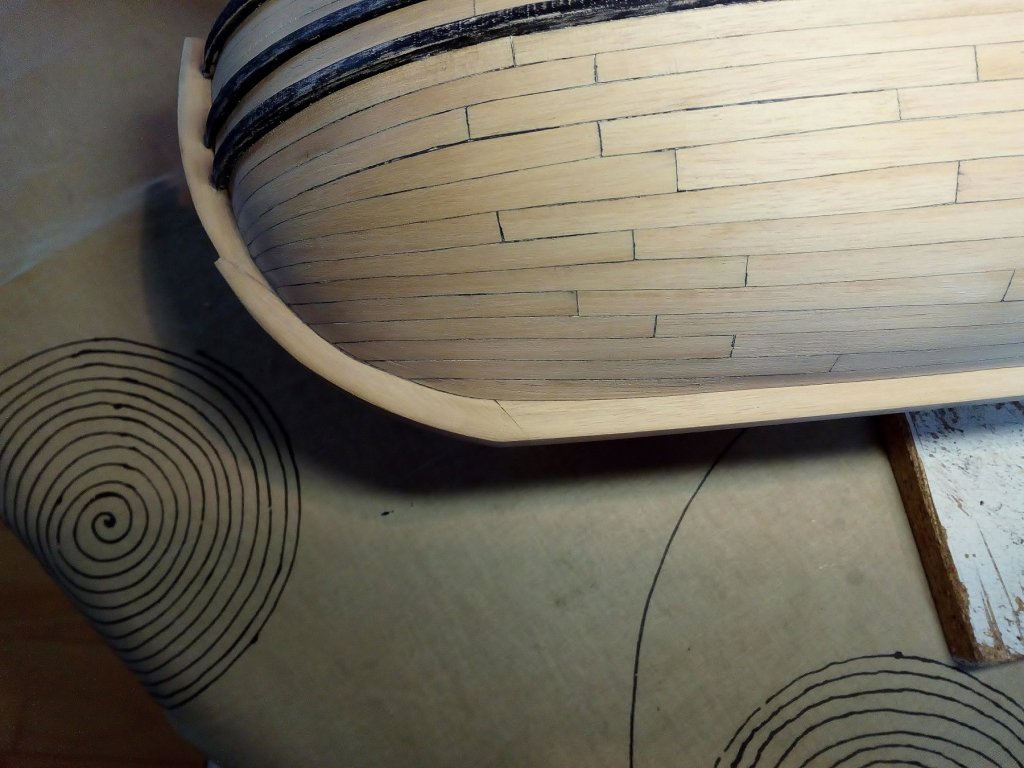
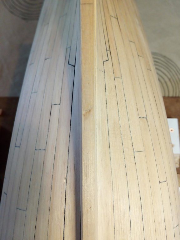
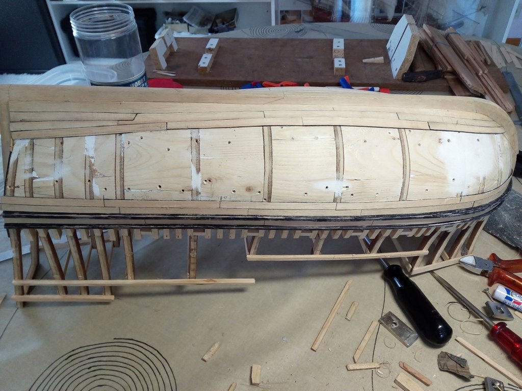
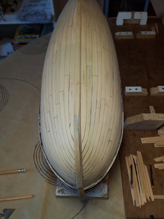
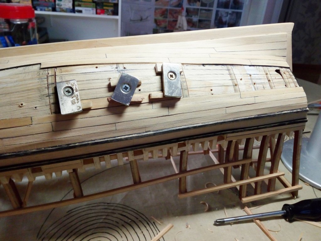
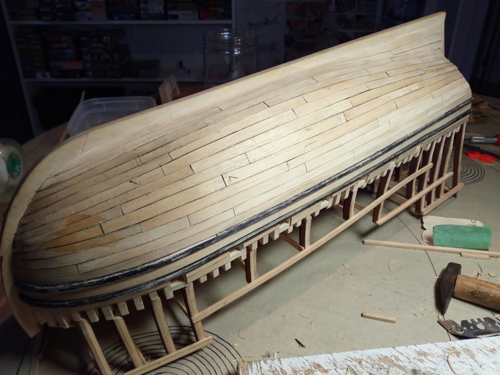
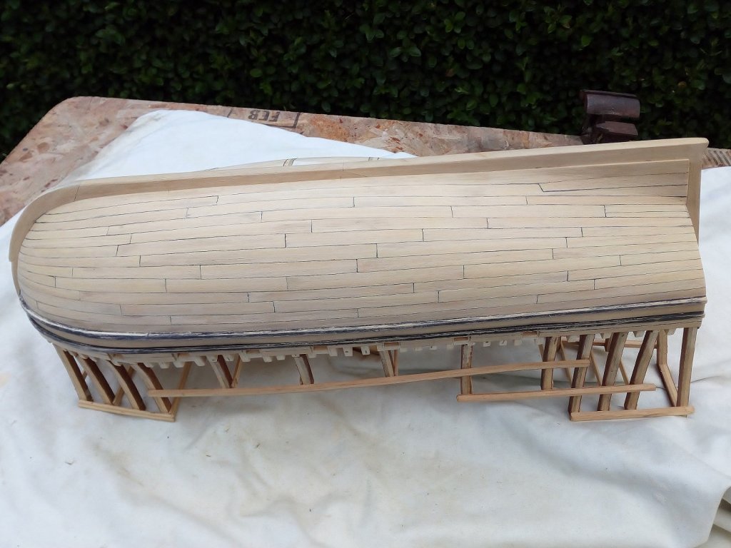
Planking the lower part of the hull (part one). First i have read the articles about planking. http://modelshipworldforum.com/ship-model-framing-and-planking-articles.php I have tried to follow the rules for planking a model ship as much as possible. To everyone who helped with this articles, they were very helpful. Thank you very much !! Following the information found the planks were 4.2 to 5.2 meters long The average thickness is 7 cm The width varied between 36 and 48 cm The widest planks were located at the bottom of the hull Source : the Gresham ship project Planking in progress Ready for sanding A first sanding is done with sandpaper grain 60. Halfway in planking the lower part of the hull. In part 2 the other half Index on page 1


- 756 replies
-
- 13
-
-
- galleon
- golden hind
- (and 2 more)


.jpg.1812d536f14f8094b3d5a999b570b6ad.jpg)