
Bender
-
Posts
213 -
Joined
-
Last visited
Content Type
Profiles
Forums
Gallery
Events
Everything posted by Bender
-
 Clark, it is good to see another Reale in the build logs. I look forward to your progress. That is a good idea how you used the wedge to keep the keel straight.
- 112 replies
-
- 1
-

-
- corel
- reale de france
- (and 1 more)
-
David, your Cutty Sark looks great. My first ship model was a Cutty Sark in plastic. I was a junior in high school back in 75. I built several more plastic over the next few years and moved to wooden when I was in my thirties. I’ve built 15 wooden ships and boats in the last 30 years. I want to build the Cutty Sark again and am always looking for the “best” wooden kit. This kit seems to be a top quality kit. After starting this kit and seeing other build longs, are you still happy that you chose this kit or do you sometimes think one of the other kits would have been better? Second question: Does the plans sheet include sail patterns? Thanks for sharing your process.
- 133 replies
-
- 1
-
-
- cutty sark
- mantua
- (and 3 more)
-
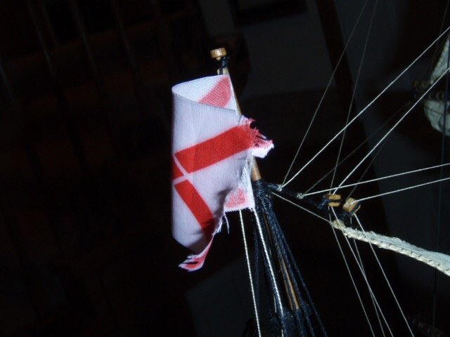
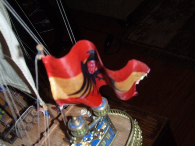
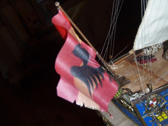
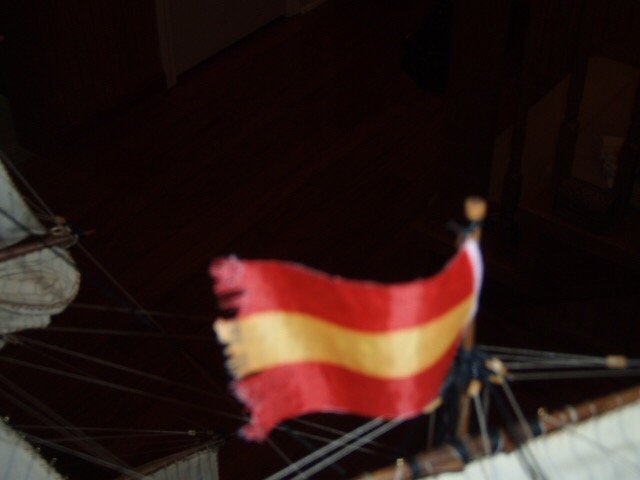
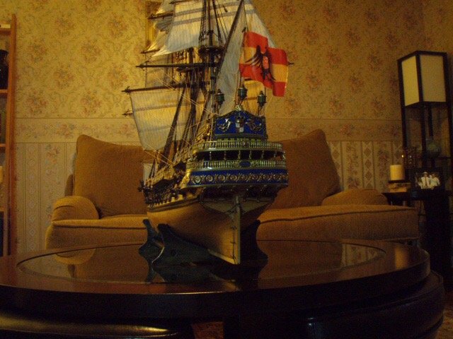
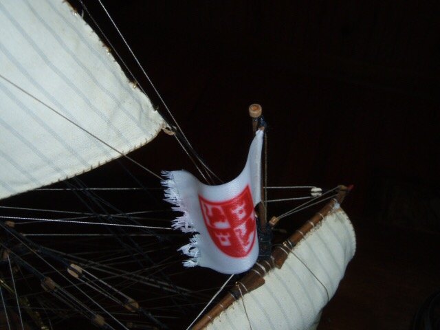
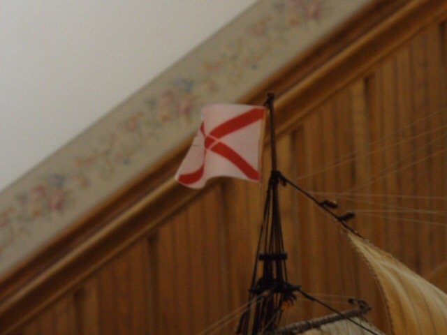
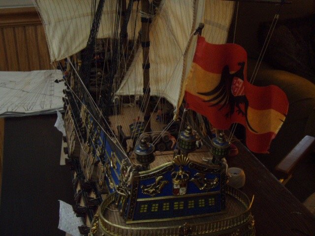
I used my wife’s curling iron to give the flags a little bit of the “wind waving” look.
-
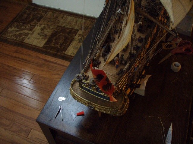
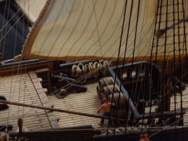
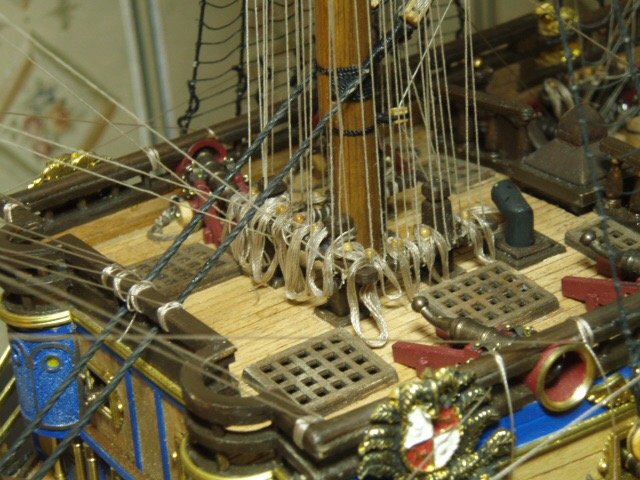
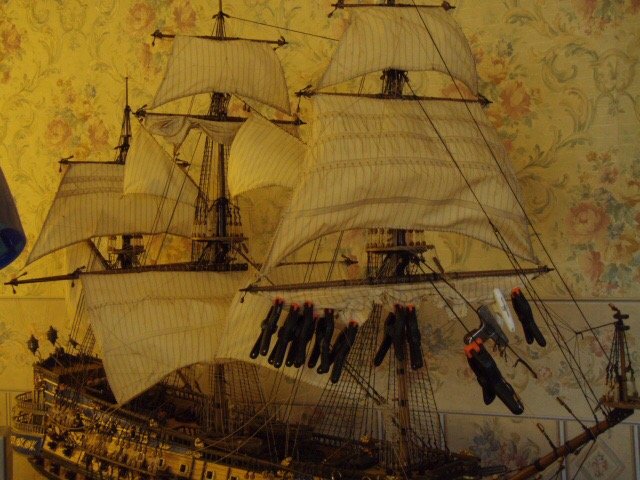
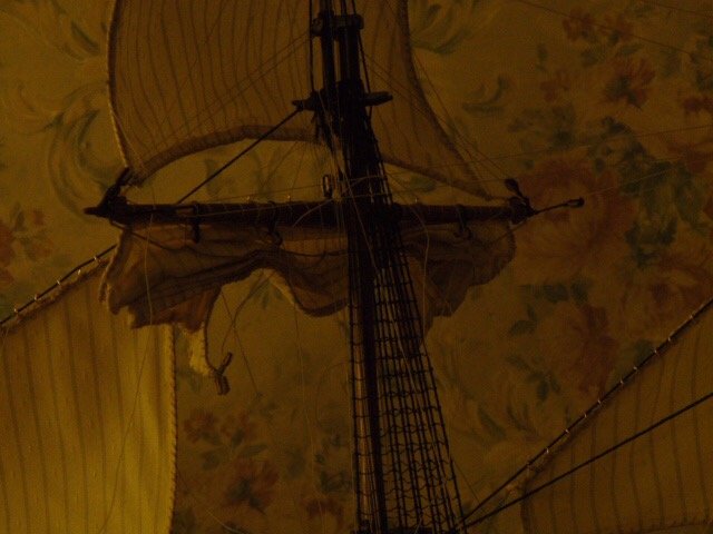
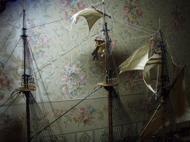
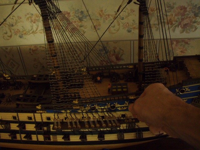
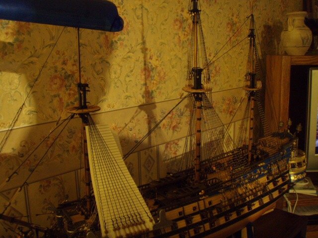
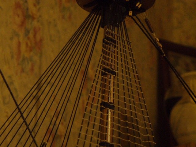
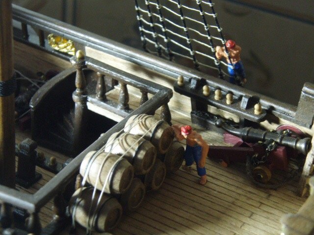
HThis is a good picture that shows the sails. For lines that are tied off at the pin rails, I work my way from the top down. For example: I start by attaching the line to the sail, run the line though all the blocks, and finish at the pin rail by poking the line through a hole in the pin rail. I press a pin in the hole to hold the line in place. When I’m finished with all the lines I can readjust the tension if needed. I don’t glue the pin in until I’m sure everything in in the correct spot, the tension is good, and no lines cross each other. I finish up by making a bunch of rope coils and gluing them to each pin. Some more pictures showing rope coils. And I had a few little plastic guys I painted and placed around the ship.
-
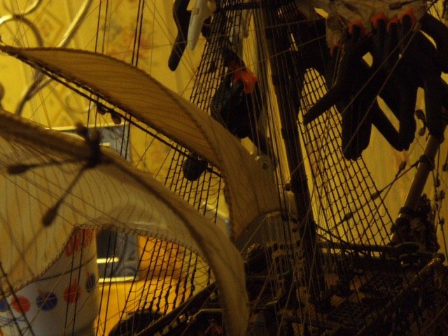
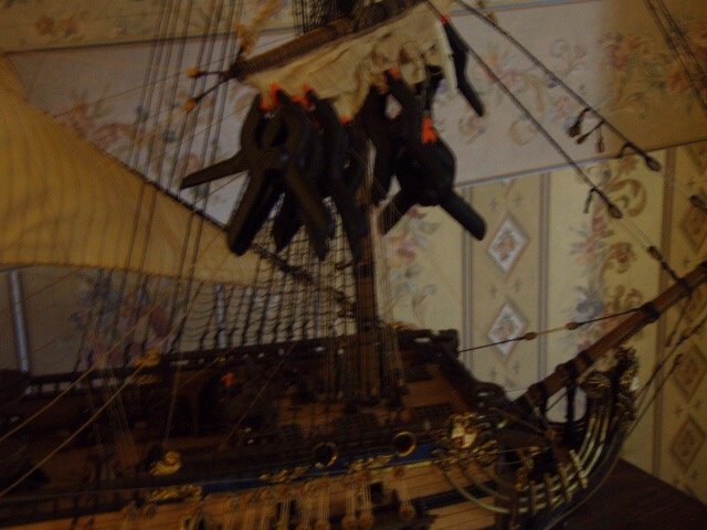
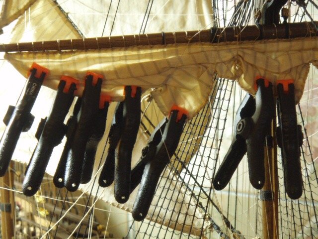
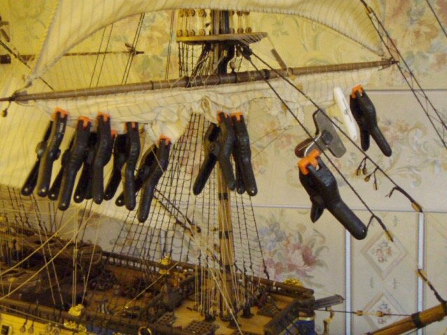
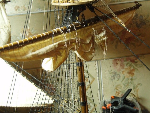
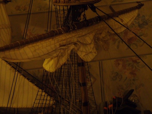
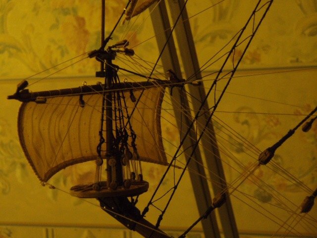
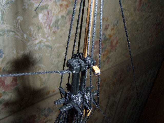
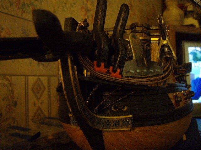
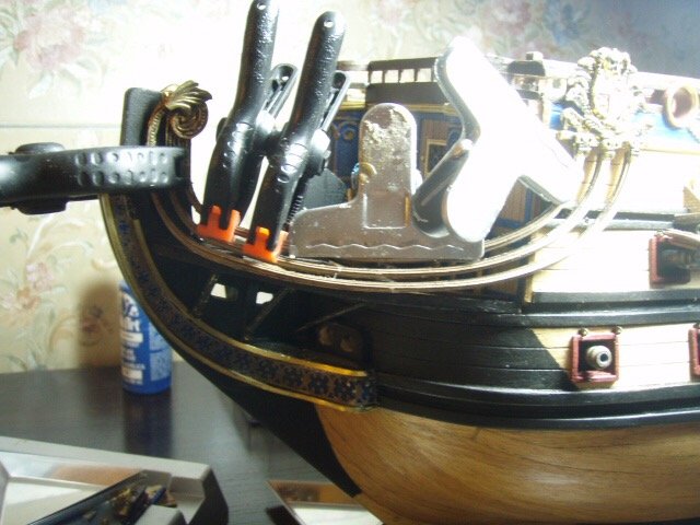
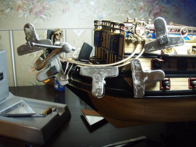
For the furled sails I attached them to the yard and coated them with diluted glue. I then tied loops around the sail were a line would crease the sail and let it dry. This process left the sail too bunched up and looking like a sail where weight was not pulling it down. After attaching the yard to the mast I sprayed the sail with more water and used a bunch of clips to give the sail the appearance of weight. And it ends up lookin like this.
-
Here’s some pictures of attaching sails.
-
Here’s some pictures of attaching sails.
-
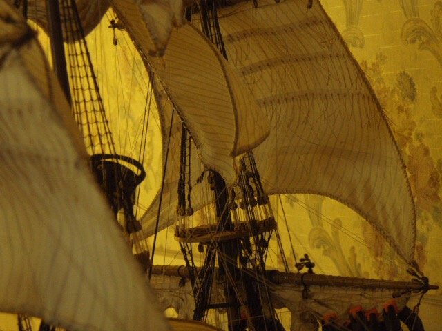
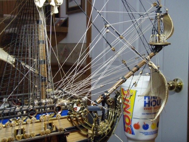
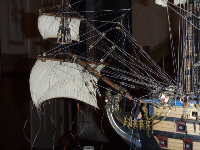
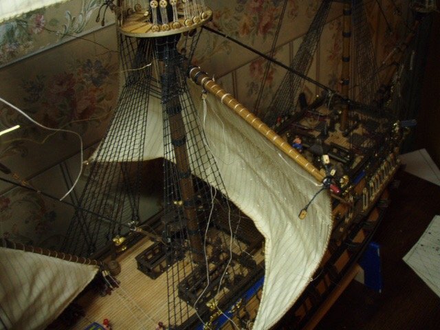
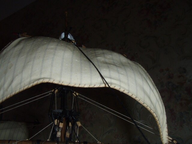
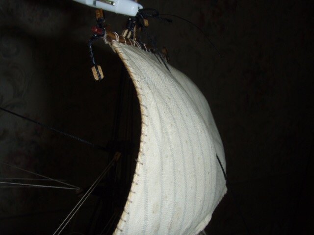
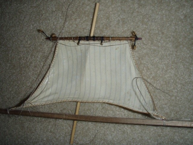
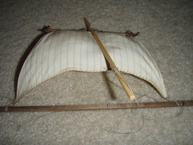
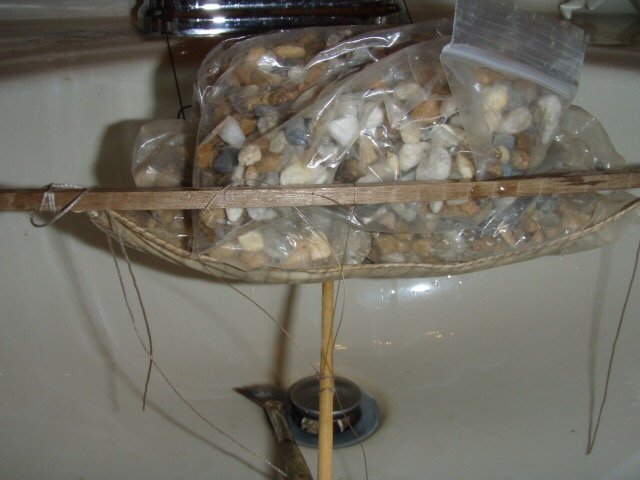
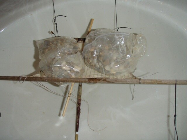
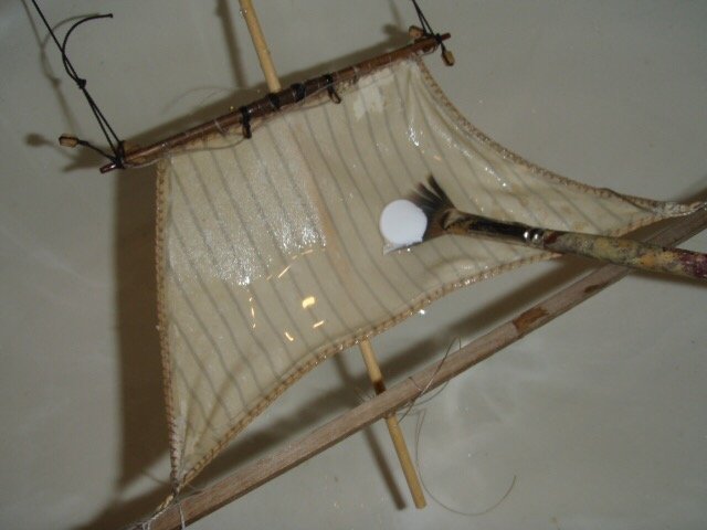
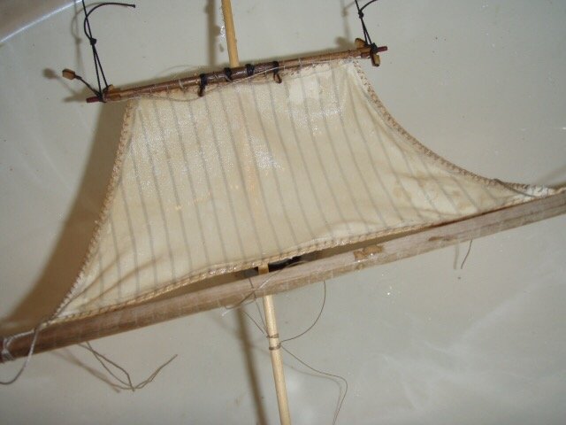
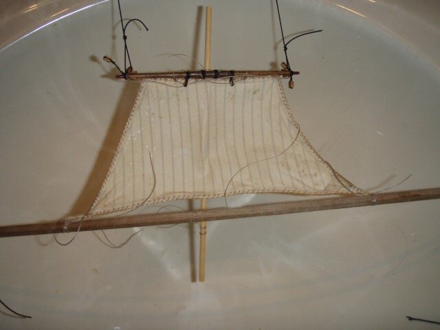
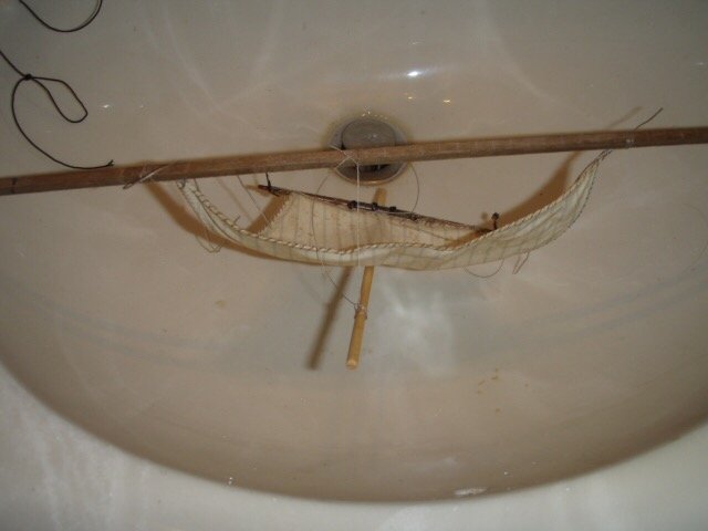
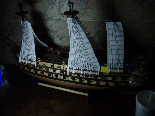
I had ordered sails from Model Expo, knowing they were back ordered. (Remember this was back in 2009.) I had been sitting around looking at the ship, wanting to do something. So I decided to try my hand at making sails. The kit comes with sail patterns. Sewing machines are not easy to use. It is easy to sew but not easy to sew in a straight line. Making a hem tiny enough for a model ship takes more practice than I have patience for, not to mention all of the parallel stitches one would have to do. First attempt found the trash. After reading more posts and tutorials here on MSW and reading on the model shipwrights’ database, I found out they make stuff for stitchless hems. You just place the stuff within the fold of the material and iron the hem. Works great. I found some thin cotton that already had the parallel lines. (Is that cheating?) I hand sewed the clew lines on and stuck myself several times. On the model shipwrights’ database, under sail making, I found several ways of making the sail appear to be windfilled. While ironing the hem, I put wire in the hem. Then after attaching the sail to the yard I made a sling in the bathroom sink (lavatory in the water closet.) Then I moistened the sail, put a little glue on it, then smoothed out the glue until the sail was evenly covered with the diluted glue. I laid little plastic bags of pea gravel on the sail and let the sail dry. When the sail was completely dry I took it to the back porch where I made another sling to hold the sail and sprayed it with lacquer. These pictures were of my third attempt for this one sail. I ended up emailing model expo to cancel the back order for the sails. It had been over two months. You can see that the sail presses against a fore stay, which is the reason for the dowel that is crossways to the yard in the above pictures.
-
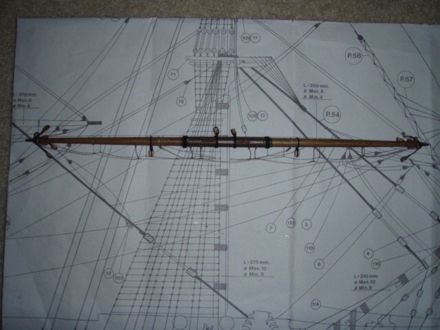
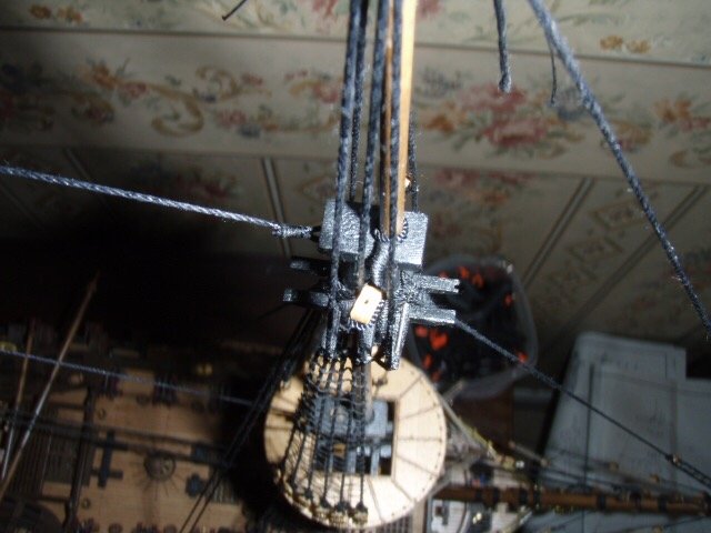
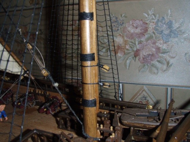
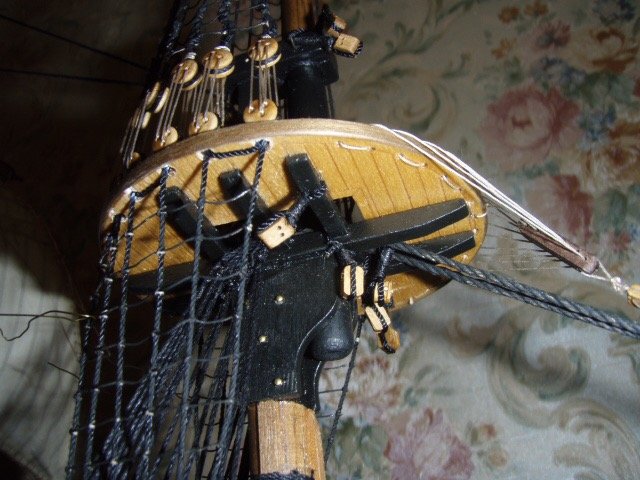
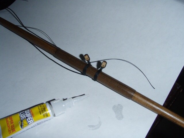
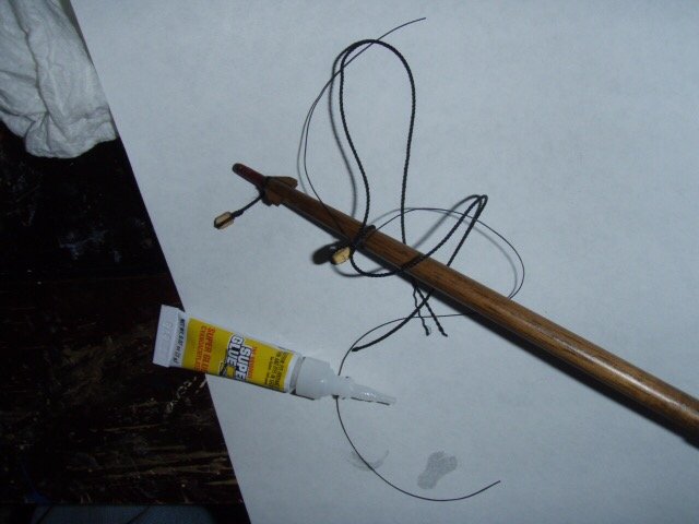
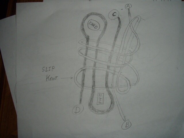
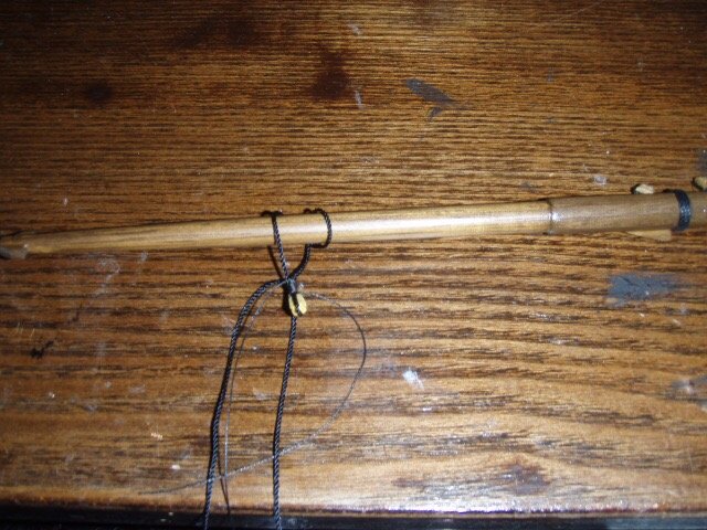
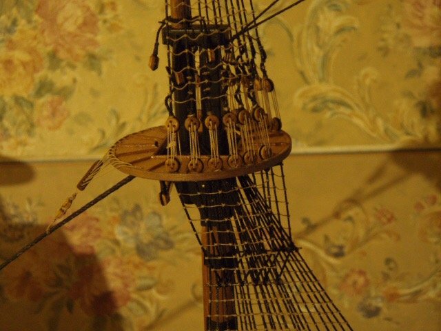
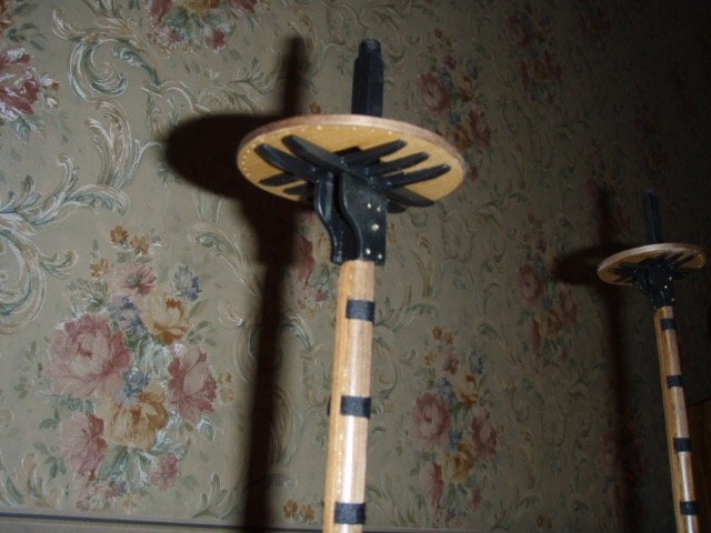
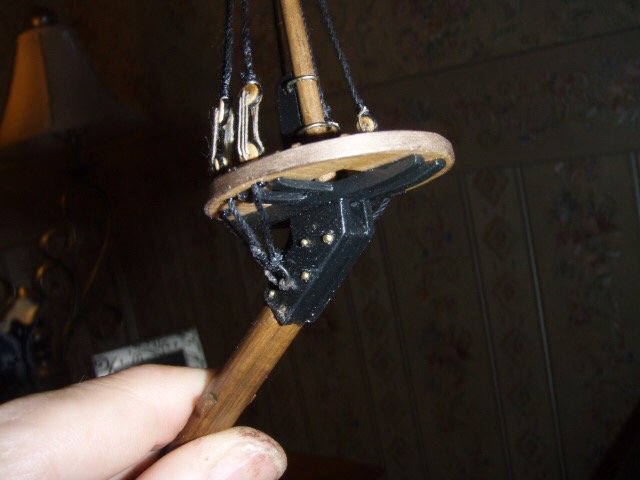
I tapered the masts and yards by chucking a piece of dowel in my drill and spinning the dowel against a bench top belt sander. When the dowel was nearly the correct size, I finished up by spinning the dowel inside a piece of folded over fine sandpaper. I came up with a “cheat” for tying blocks to yards, masts, and tops. I made a crude drawing. The thinner thread—with ends marked A and B—can be wrapped around the thicker thread four times to as many as ten or more depending on the length you need. I usually tighten the thread around the block first and then slip the other loop around the yard or mast. A drop of CA glue holds it. I’ve never had a block come loose using this method. If the block is attached to an eye, I thread the string through the eye and then do the tying as shown in the crude drawing above. Here is a link to a post I made several years ago that better explains this method. http://modelshipworld.com/index.php/topic/1056-tying-blocks-to-yards-or-masts/?p=17489
-
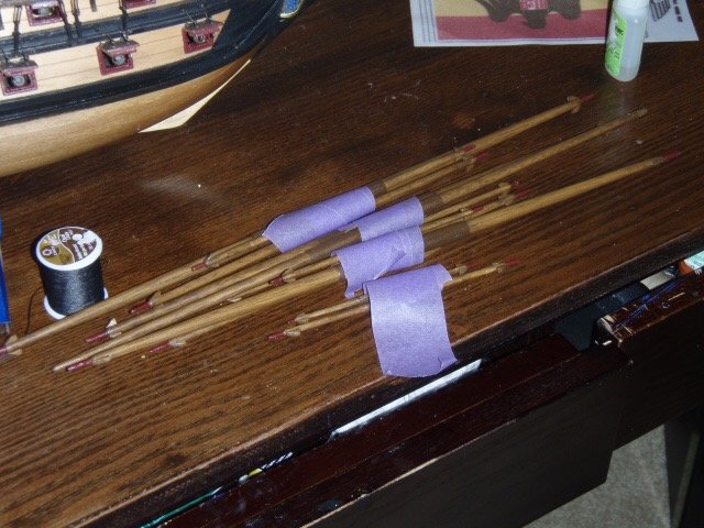
Pictures of ratline tying. I used Microsoft Excel to print parallel lines the correct distance apart to keep the ratlines straight, level, and uniform.

-
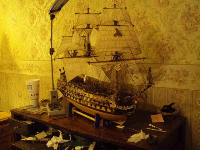
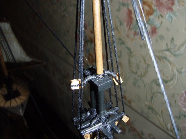
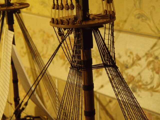
Notes from 8/6/2009 Everything is built: nothing but rigging left. Although, I am still trying to build a ship’s boat by scratch. Two attempts have left me with nothing I would want to show off. I will try one more time. If after this third attempt and the ship’s boat does not look good I will go with the kit supplied plastic/ wood boats. I have all the standing rigging on the bowsprit, all the forestay on the fore mast except for the fore topgallant stays, the ten shrouds on the fore mast, and one fore stay on the main mast attached. A thought occurred to me at this point: There are 10 shrouds each side on the fore mast, the main mast will have 12 shrouds each side and the mizzen mast 6 shrouds each side. I started thinking: that’s going to be a lot of ratlines. . . a lot of ratline knots. So I multiplied shrouds by ratlines, added up those from each mast and came up with 3110 knots. The plan—when the time comes—is to tie 100 knots a day for 31 days. We will see. Rigging really is my favorite part. I have decided to add sails; this requires 96 additional blocks tied to masts, yards and stays.
-
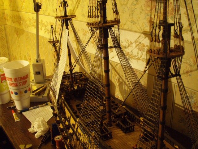
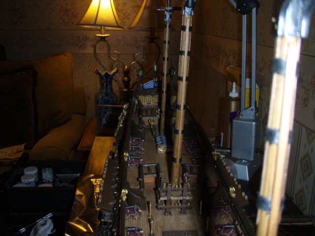
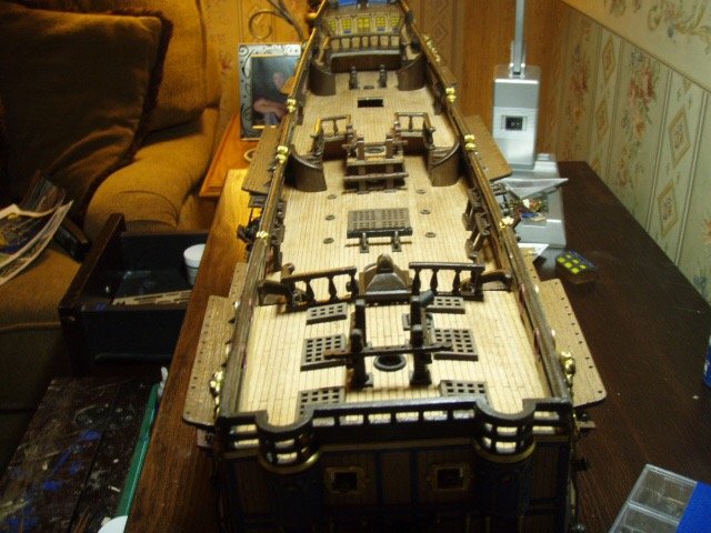
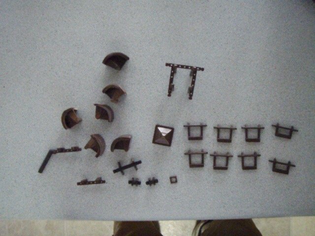
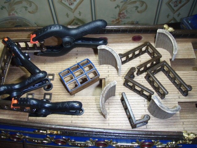
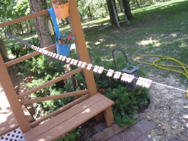
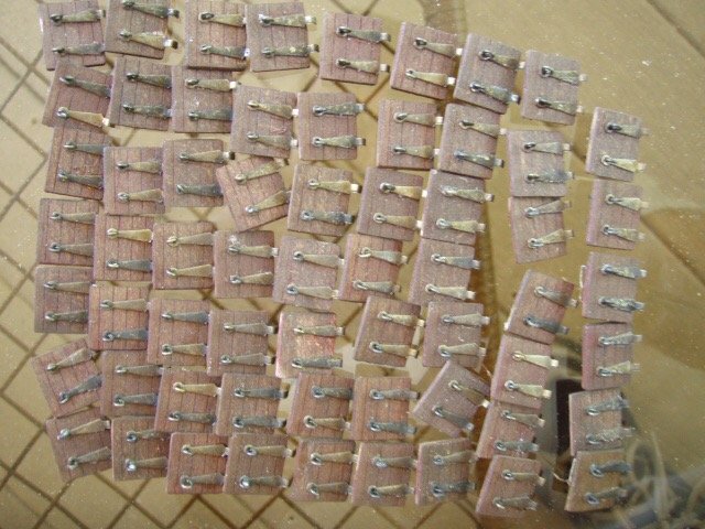
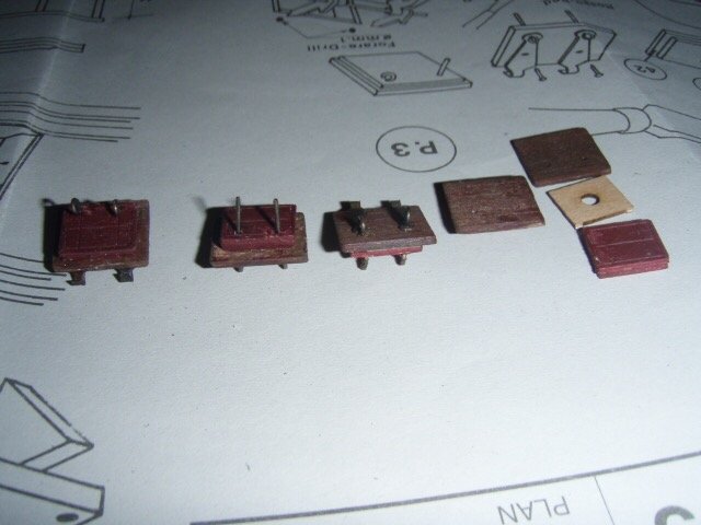
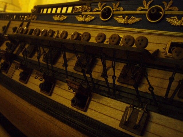
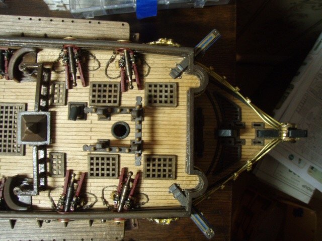
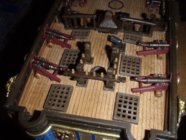
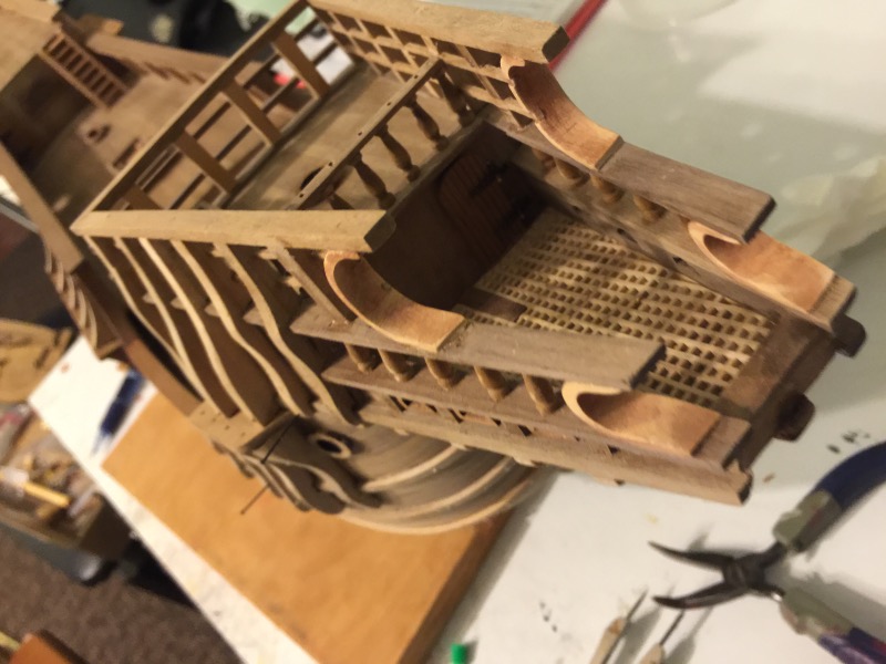
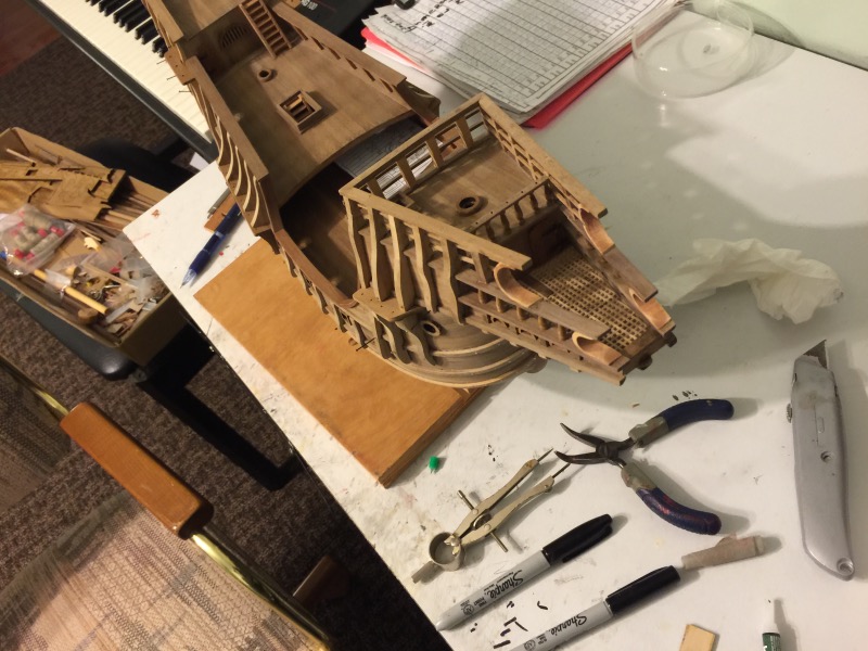
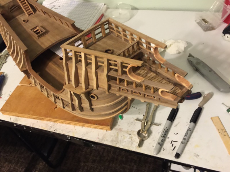
Thought I’d attach a few random pictures that I left out. Parts of the lids for the cannon ports. All the lids finished and ready to be painted. I strung a string through the eyes of the port lids and hung it out out to paint. Rails, stairs, pin rails Skylight and stair rails
-
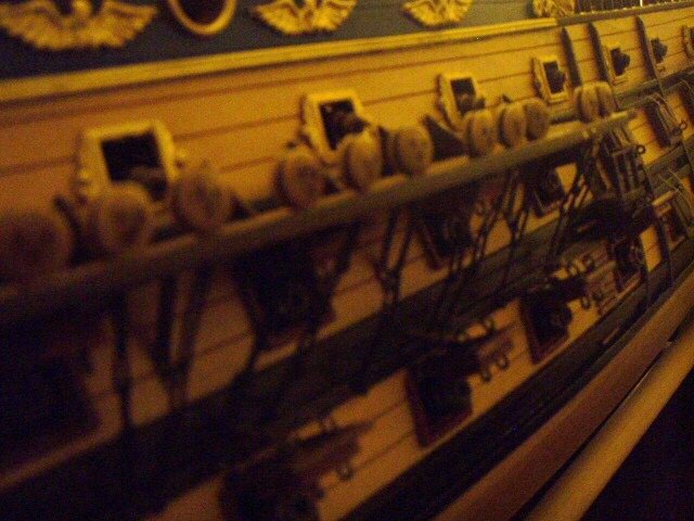
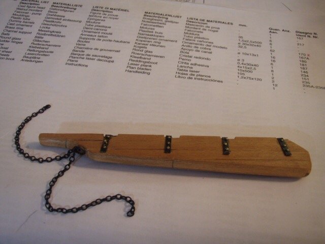
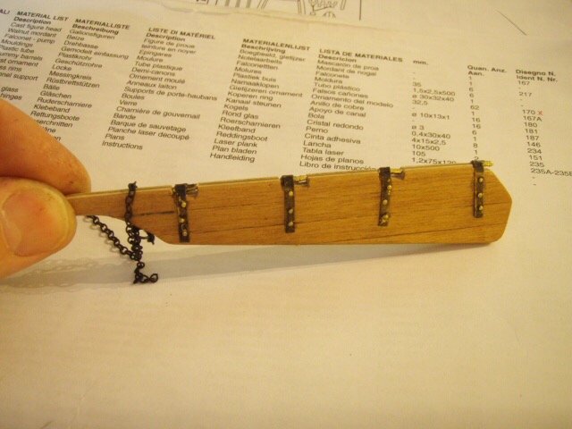
Notes from 7/23/2009 I have never soldered anything before this build, so to say I could not solder is an understatement. And now after soldering 66 sets of chain plates—many of them four of five times—I am better but still cannot solder very well. The tutorials are a big help. I did not know how to start, so I went through the tutorial over on the left: “A guide to Silver Soldering, by Russell Barnes.” I found the needed supplies that Russell Barnes suggested at Ace Hardware. I would solder a link then test it by inserting a length of wire in the link and pulling with a little force. If it broke I would do it again—sometimes as many as five times. After three to five times though, the ends of the wire forming the link would be burned short. The kit supplied 66 of the middle links. I ended up making 52 because of burning the kit supplied links. I got a lot a practice, a whole lot. Of the last ten links, only one link had to be soldered for a second time. There is a learning curve. The chain plates were the last of the hull building. Now starts my favorite part: masts, yards and the rigging. I started with the bowsprit.
-
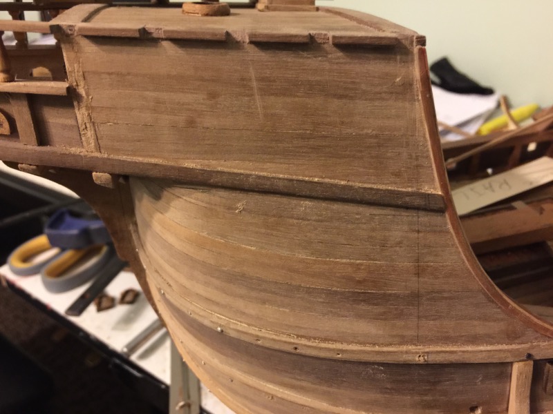
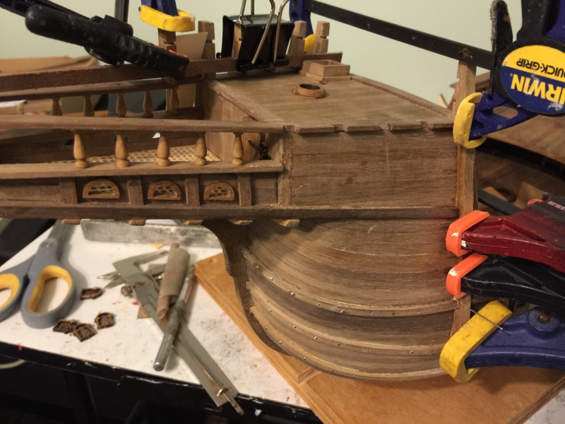
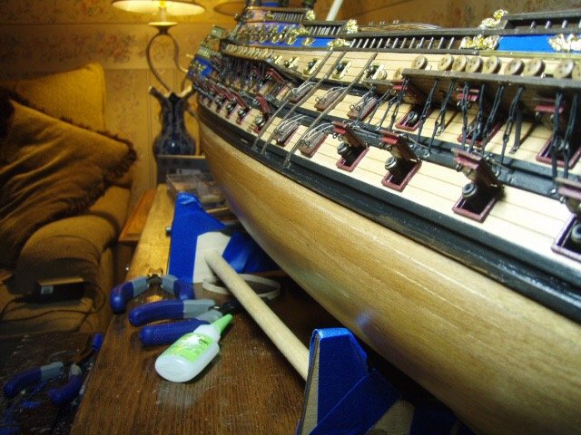
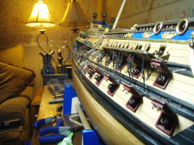
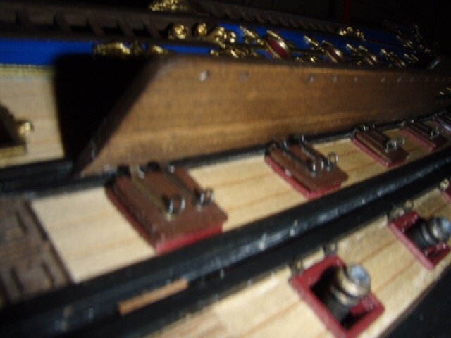
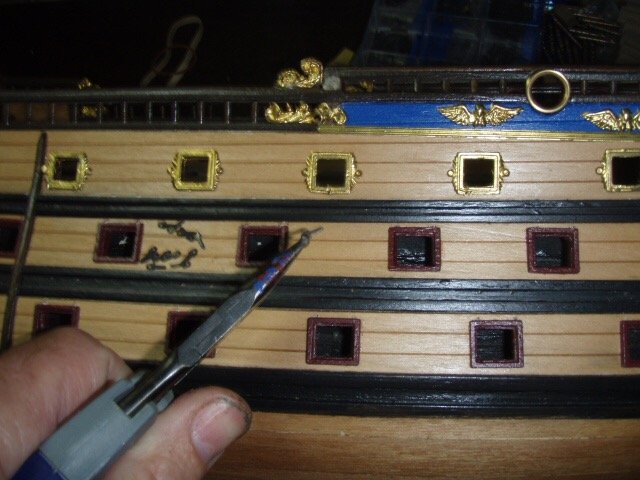
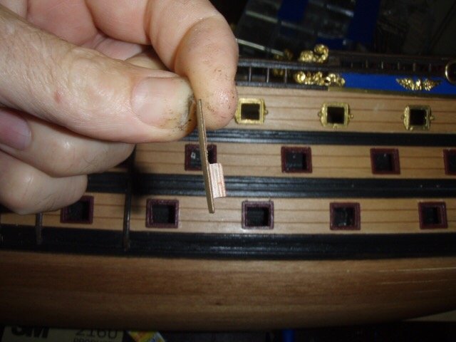
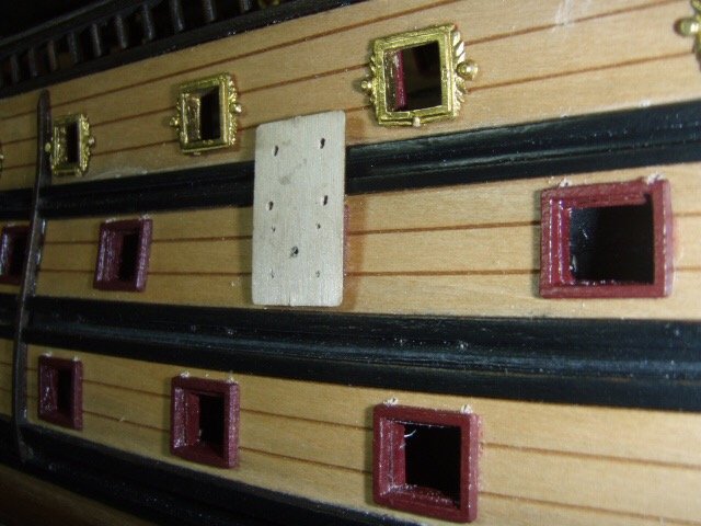
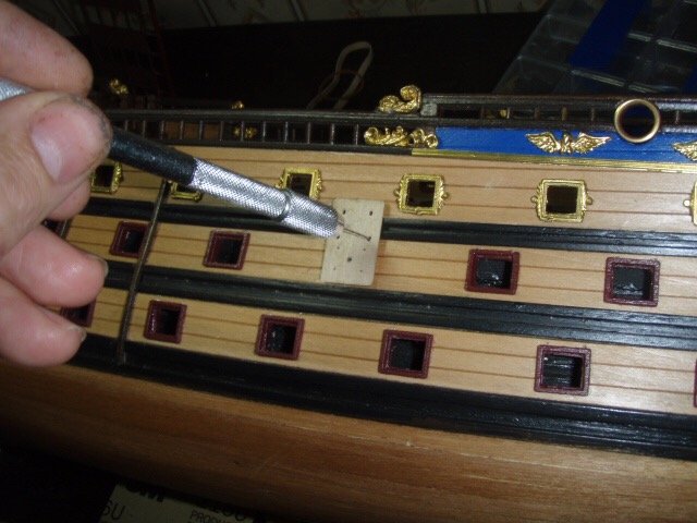
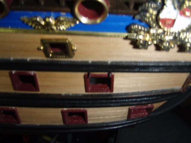
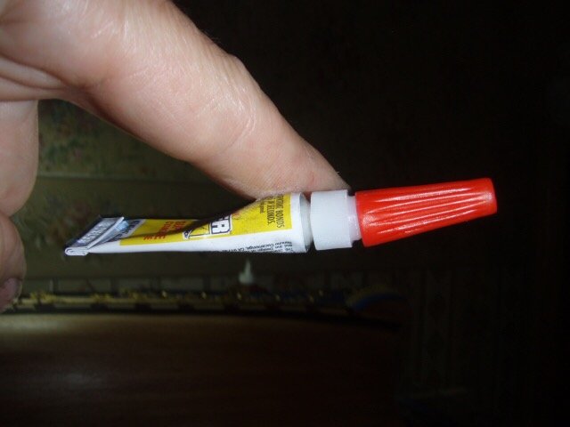
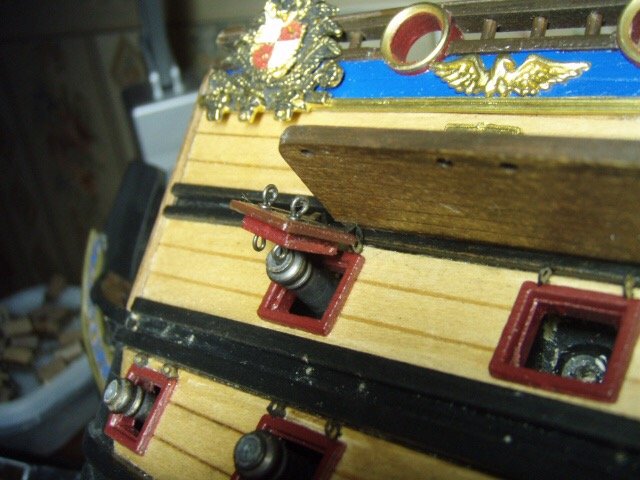
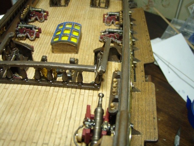
Notes from 7/14/2009 Mantua supplied a jig for drilling the two holes for the gun ports lid’s hinge pins and the two holes for the rope that would open the lids. After drilling the holes, I inserted the hinge pins. And glued the glue tube to my finger. There was a problem with the supplied drilling jig. After installing the channels, the holes for the lid ropes are above the channels. Also, as I was drilling the holes for the middle roll of guns, ( note in the picture above the white scuff marks above the rubbing strakes) I noticed the drill bit was piercing the hull inside above the main deck. I ended up having to put down a waterway to cover up all the holes. Another problem. With the lid up the eye-bolts hits the bottom of the channels, but the lid does not open high enough. On one side I left the ten lids under the fore and main channels closed. On the other side I clipped the eye-bolts off and glued the lid open.

-
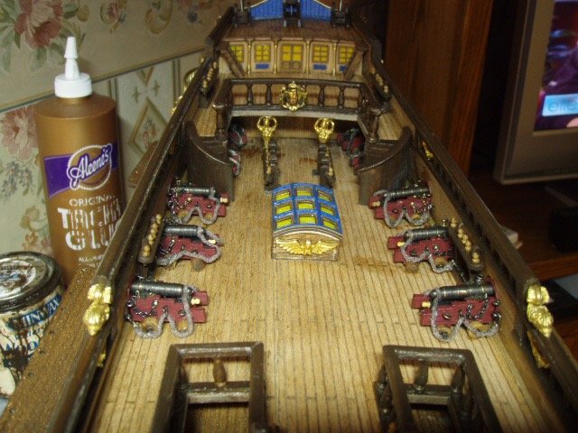
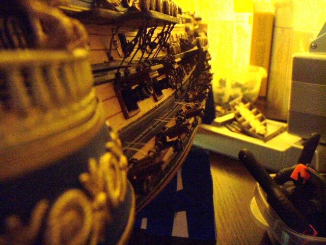
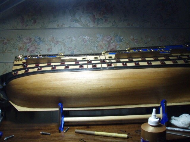
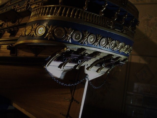
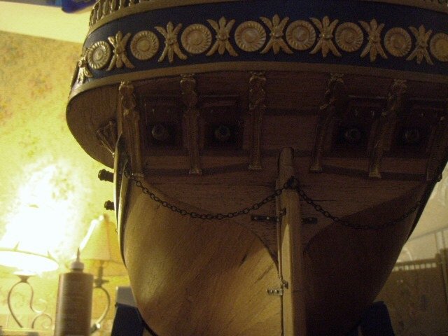
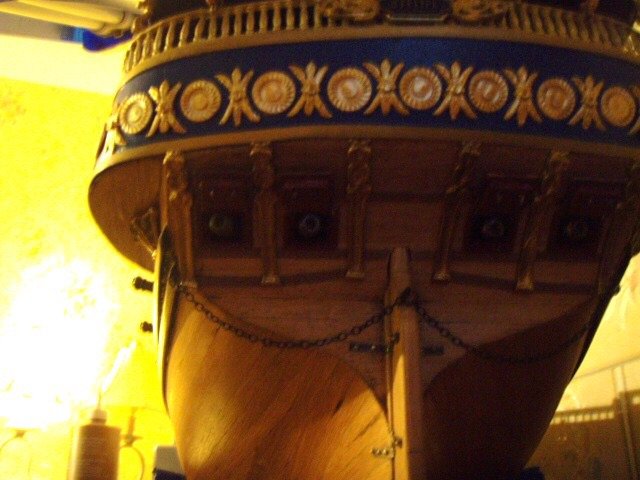
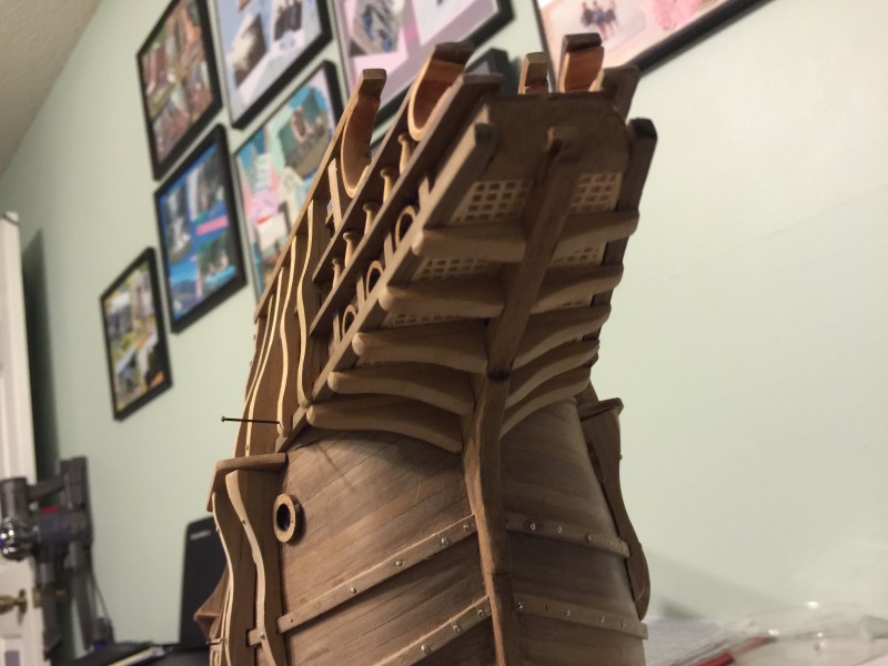
Some more pictures and notes from 7/7/2009. I glued the last of the brass on. My next build will have no brass. The last four gun ports—the four under the curve of the transom—are finished. The last four guns ( chasers ) are in. And I’m in the process of installing the gun port lids. I have discovered a problem with some of the lids and will write about it on my next post. While the ship was up-side-down I built and fastened the rudder. When I turned the ship back over I discovered I had damaged the hand rail. A little CA glue took care of that. And some more pictures.
-
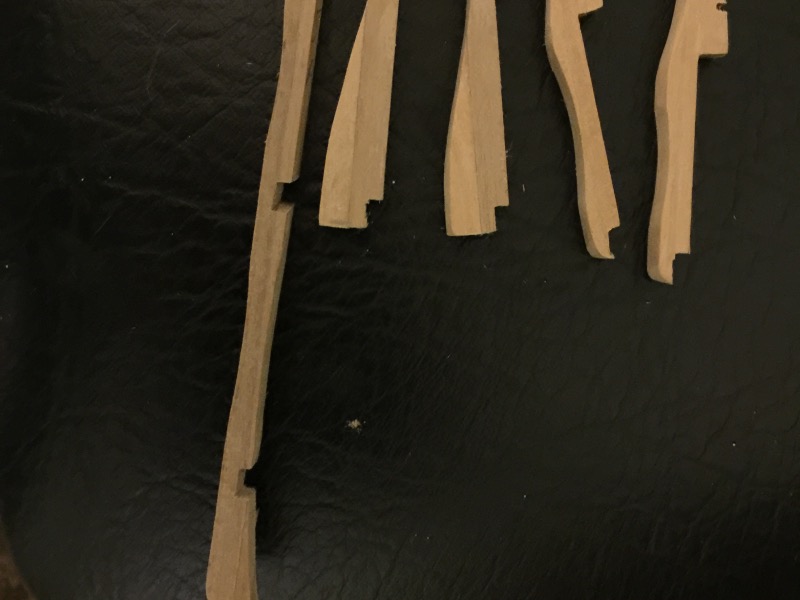
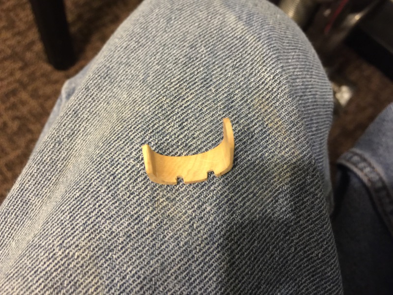
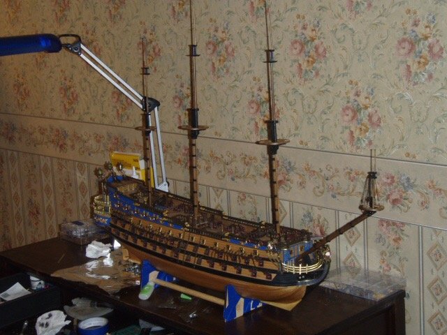
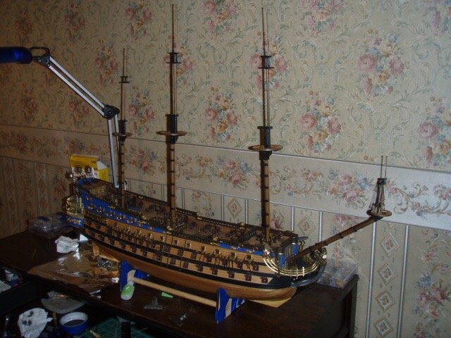
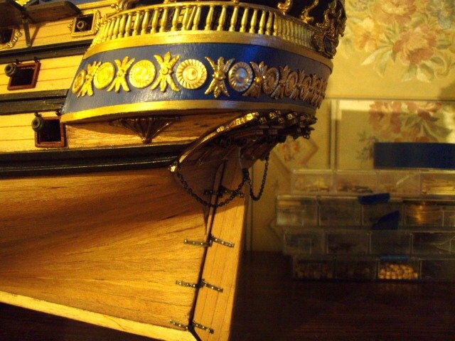
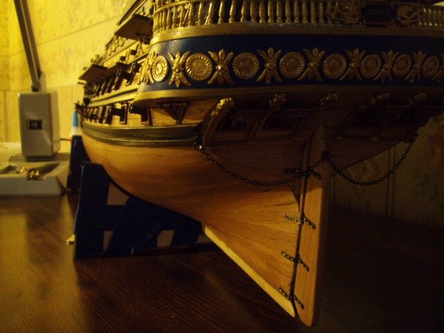
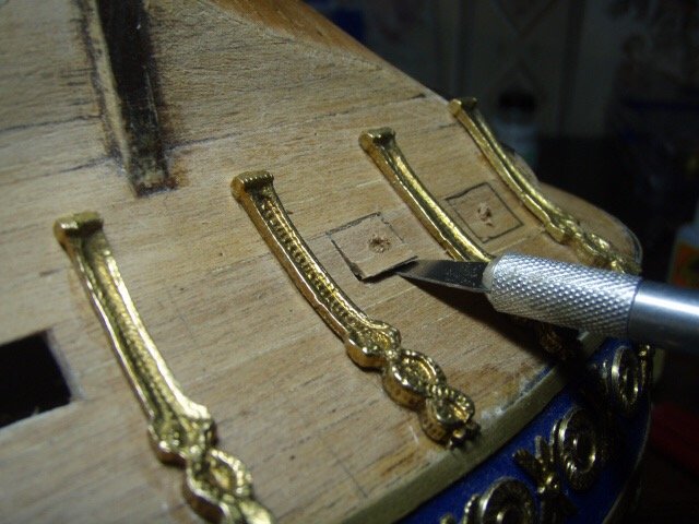
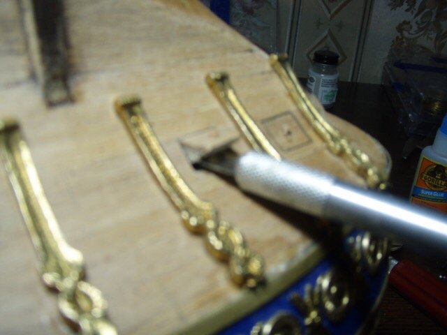
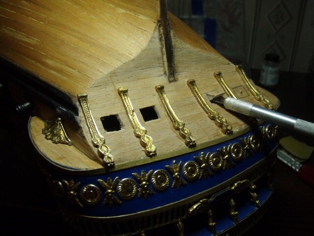
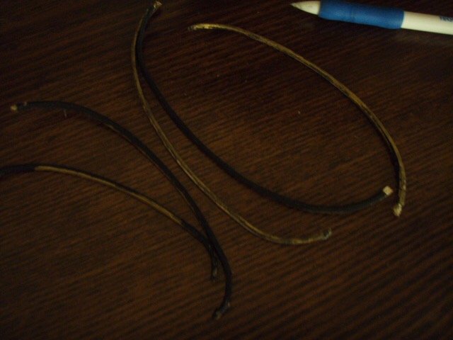
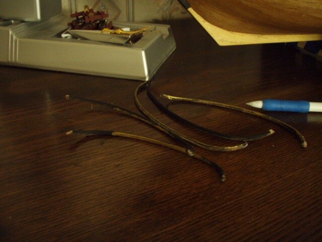
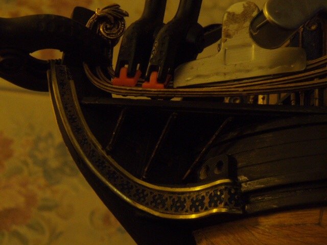
It’s been awhile. I found the San Felipe pictures on my old lab top, and wanted to post the rest of the build. This was in my notes from July 3, 2009. Headrails? I think the headrails must be the most fragile, frustrating, grueling, ambiguous, vague parts to build on a ship. For each single rail, the kit supplied three 1mm X 3 mm strips of plywood. The plywood strips had the correct shape in two-dimension ( c-shaped ). Two of the three strips are glued together and glued in place which give the rail its shape in the third-dimension. The third plywood strip is then glued to the other two. The first two pictures are of the strips being glued in place. The next picture is the rails after I removed them the next day. The next picture shows the rails I made of brass strips. These brass strips are glued and nailed to the stem and hull. The last pictures shows the catheads and the falconets. I decided to have just a breaching rope on the falconets. Three layers of ply. I was afraid it would be too flimsy. I replaced with brass strips. Finished headrails. Trying to clamp the flimsy ply headrails. Another picture of the ply headrails. Another showing an attempt to attach the ply headrails.
-
How to make sail look like wind is blowing in them
Bender replied to ranikola's topic in Masting, rigging and sails
I don’t know how to get to the correct post, but look down about half way on this third page. -
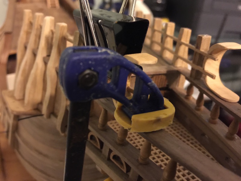
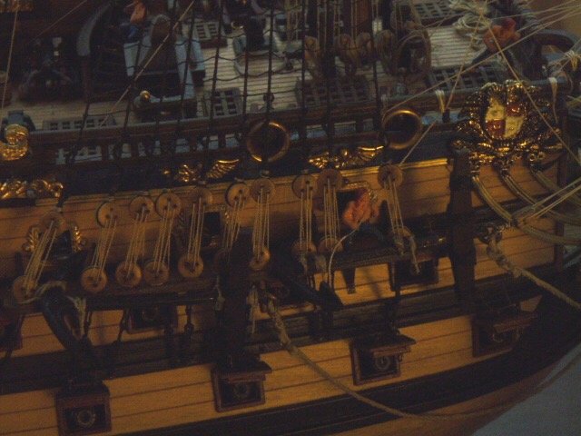
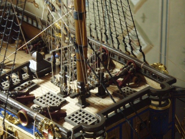
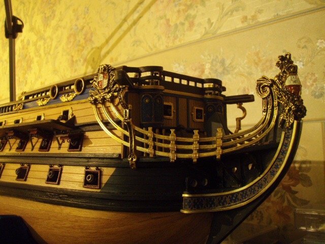
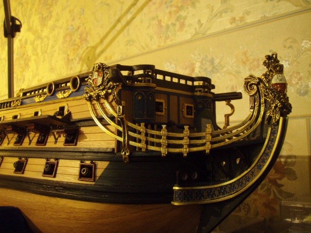
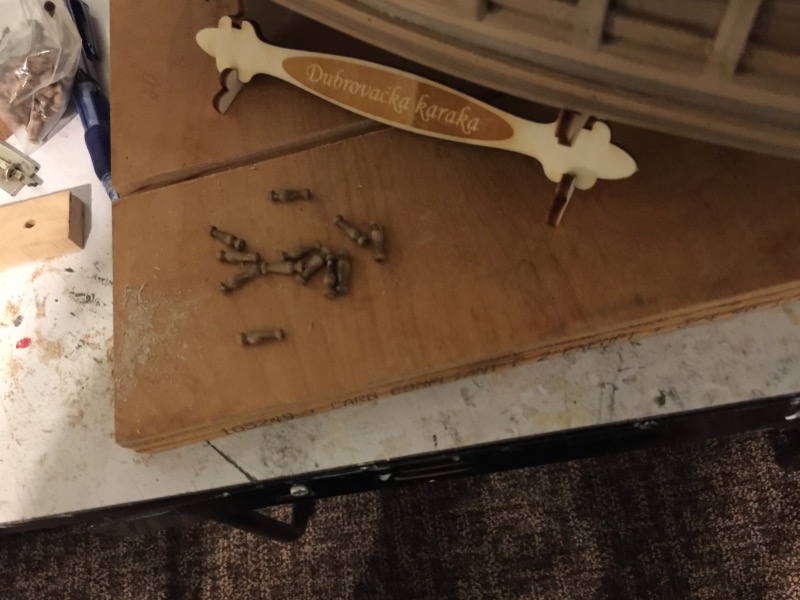
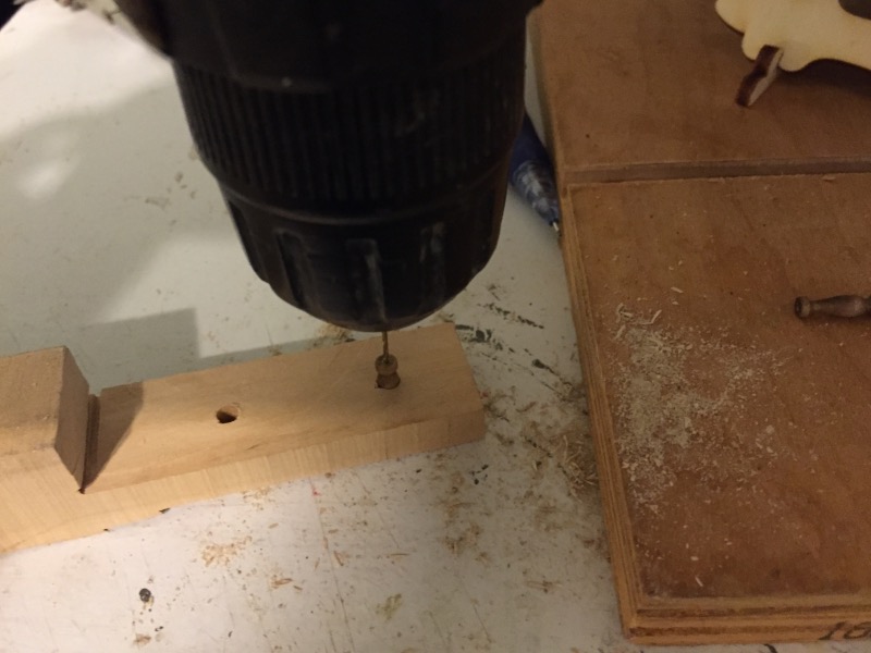
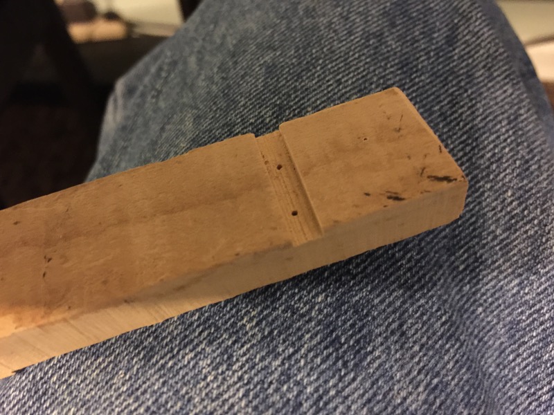
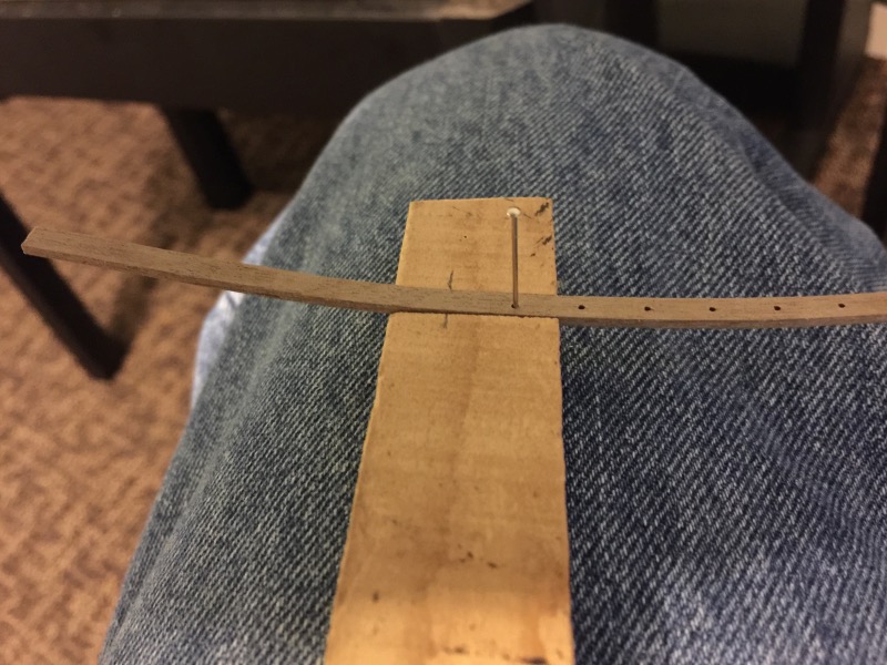
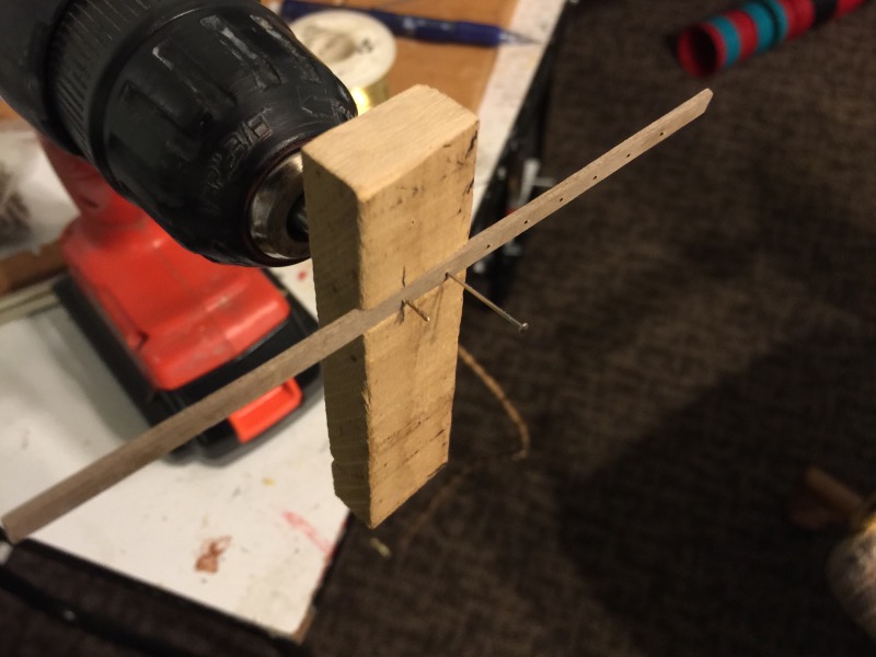
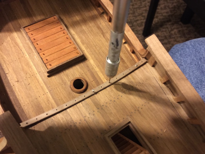
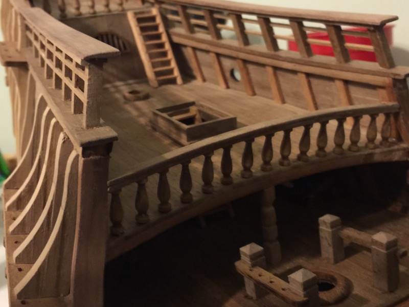
Don, thank you much for your comments. It is alsways good reading your replies. This is the same picture I posted in the above post, but this time I'll talk about the railing on the bridge deck that overlooks the main deck. The kit doesn't come with any spindles. I bought these spindles from Model Expo many years ago. I ran a brass wire all the way through the spindle so that the spindle is attached to the deck and the rail. The belt snapped on my mini drillpress last winter so I had to drill the hole with a handheld drill. My fingers got tired of holding the tiny spindles, so I made this simple holder. I needed a bunch of them. Here are the spindles strung on the brass wire. The bridge deck has a nice curve. I soaked and bent the rail to shape before drilling holes in it. I made this jig to make sure I had the holes centered in the rail and evenly spaced. I drilled one hole and then used a pin to hold the rail in position to dry the next hole. After drilling all the holes in the rail, I used the rail to drill holes in the deck. Here the railing in place.

-
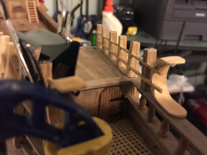
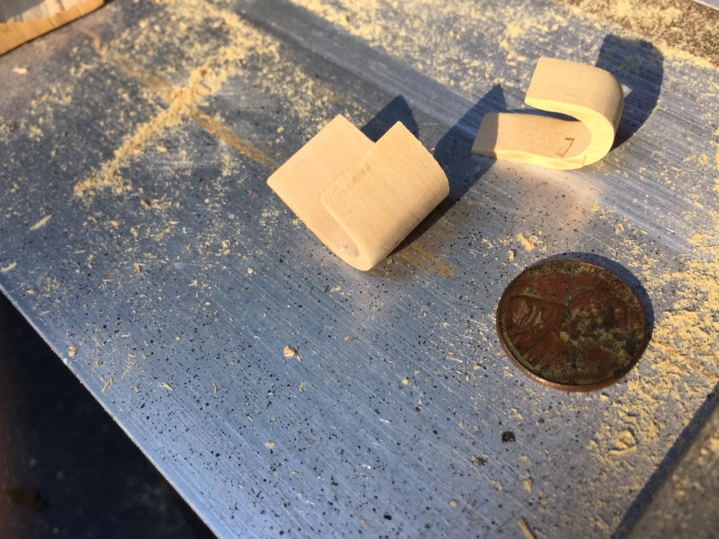
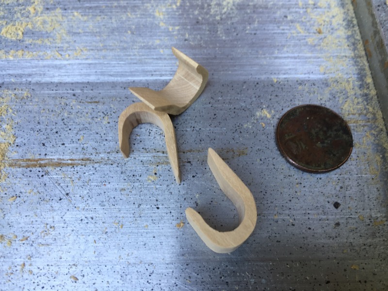
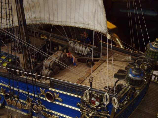
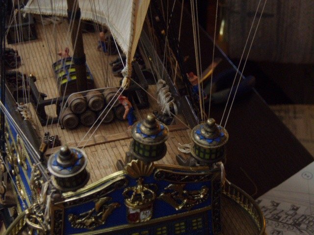
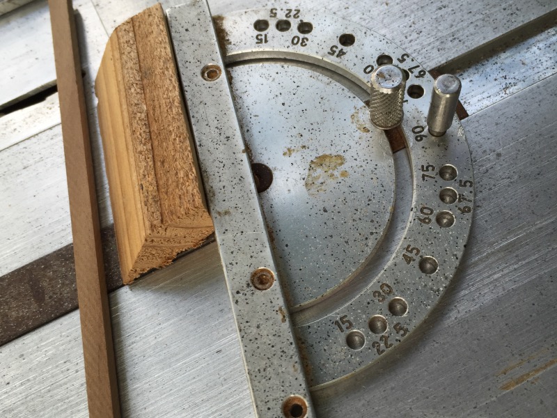
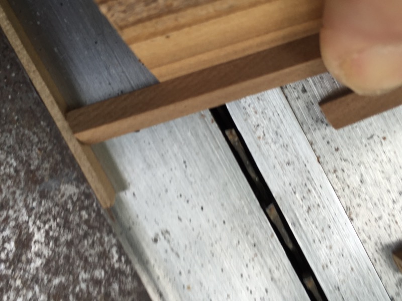
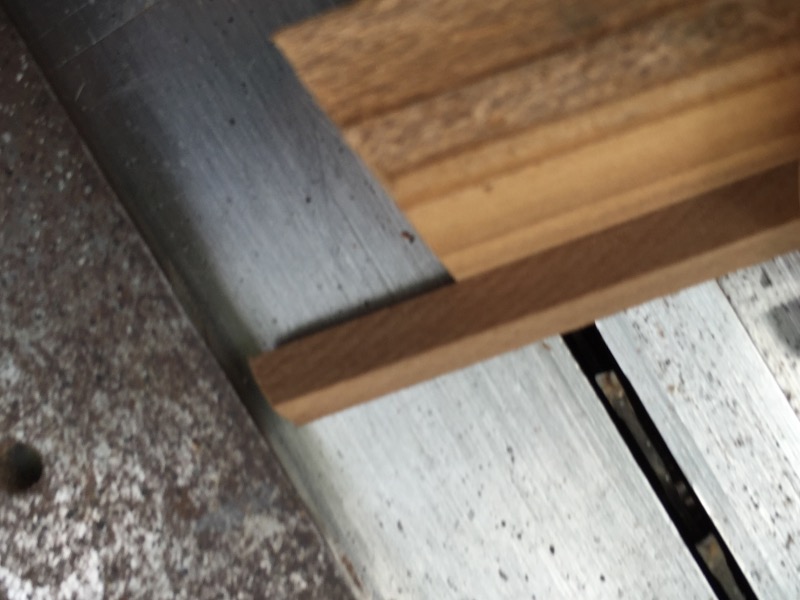
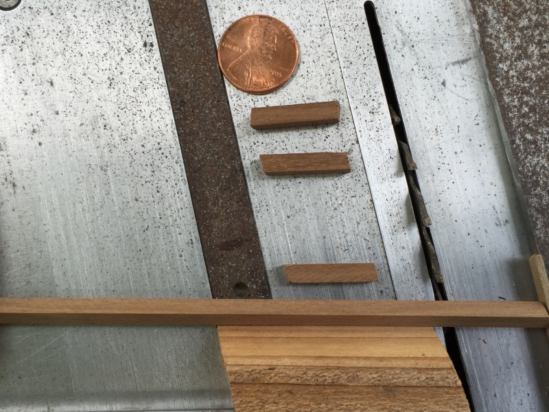
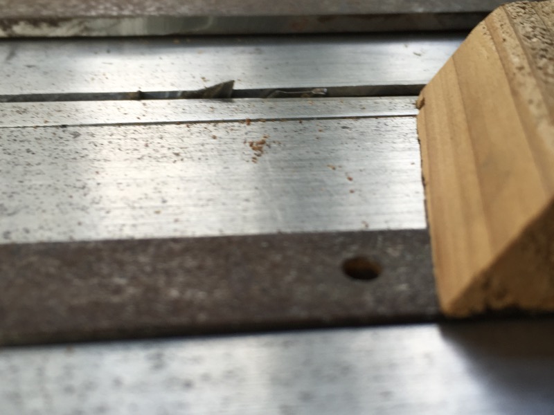
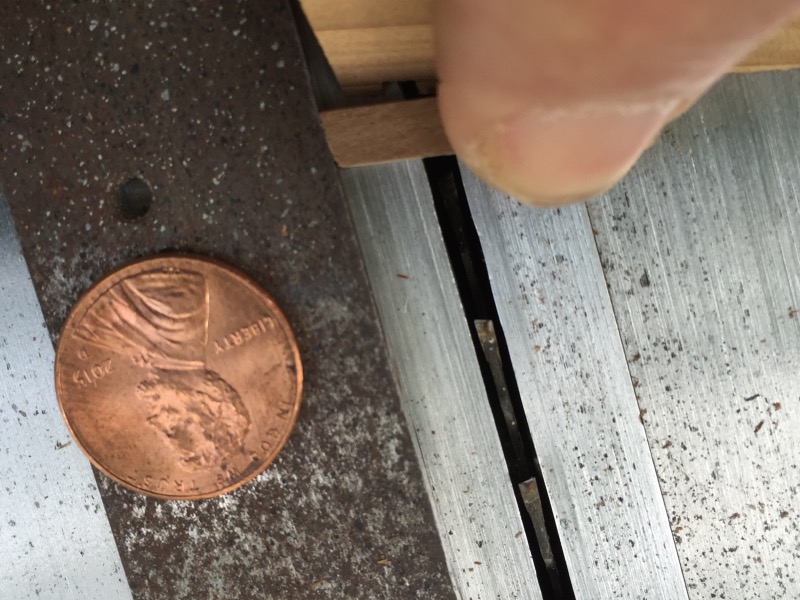
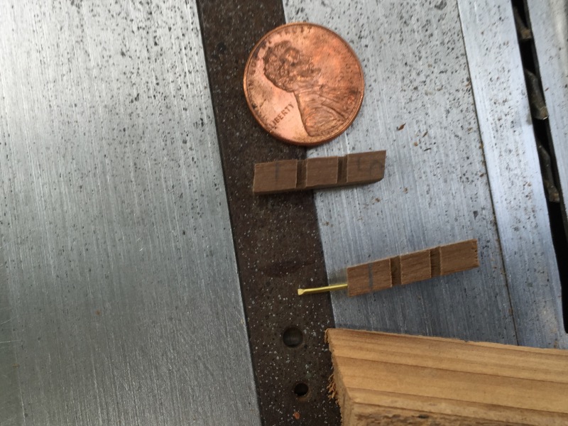
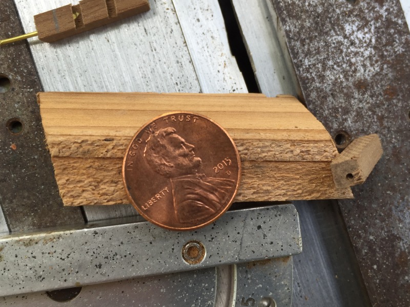
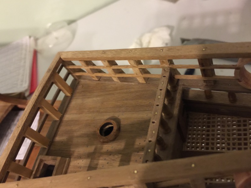
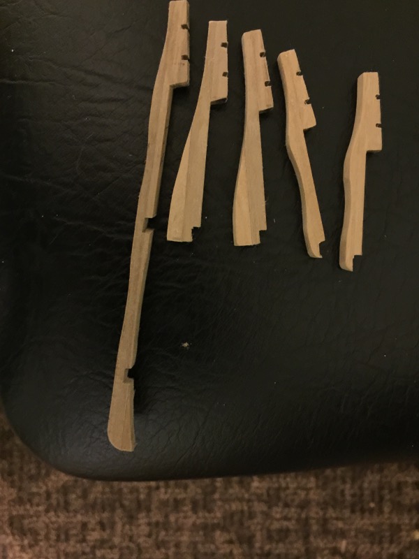
It seems like the rail would be high enough, but I guess these guys didn't want a sea monster climbing on board. This rail sits on top of the bridge deck railing. These are the rails at the left and right edge of the next picture. and the top edge of this picture. Each post leans in toward the center line. See the top picture. And sits vertical on the top rail that runs at a slope. See second picture. The Byrnes saw does not have a tilting blade, so I came up with this way of cutting the needed compound miter. By placing this piece against the t-slide and holding the 4X4 Tilted back against this piece at 45*, and setting the t-slide at 73*, I was able to get compound angle. I Used a spacer between the 4X4 and the saw fence to keep the cut piece from wedging between the blade and the fence and flying away. You can see the gap between the piece and the fence. I needed 14 posts but cut 25 pieces. After cutting the 25 pieces, I needed to cut two slots in each post to except the horizontal rails. Here the blade is 1.5 mm high. My fingers were very close to the blade when I cut the slots. I couldn't get an actual picture of me cutting these pieces. By using the wood piece against the t-slide, I was able to keep my finger further from the blade than this picture shows. Here is what the slots look like. I also drilled a hole in the bottom of each post and glued in a brass pin.

-
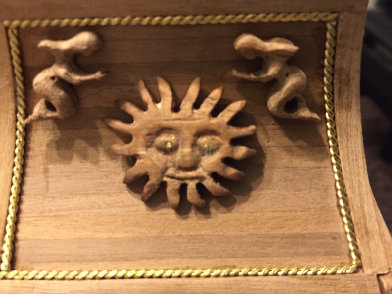
Thanks for the very kind words on the "carving." I look at the carving from other build log and am in awe of their skill. I am not yet in awe of my skill, but hopefully I will get better. This Friday I'm going to try again and see if I can get it a little better.
-
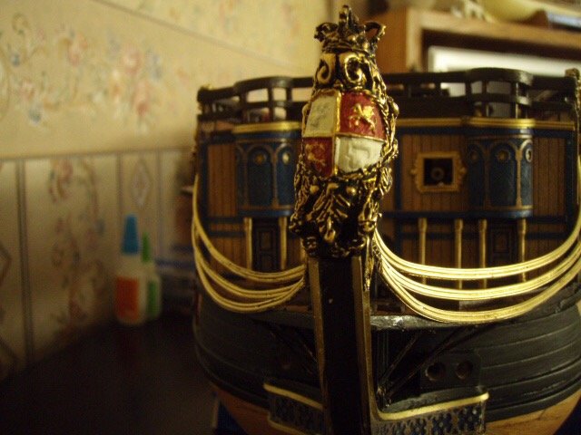
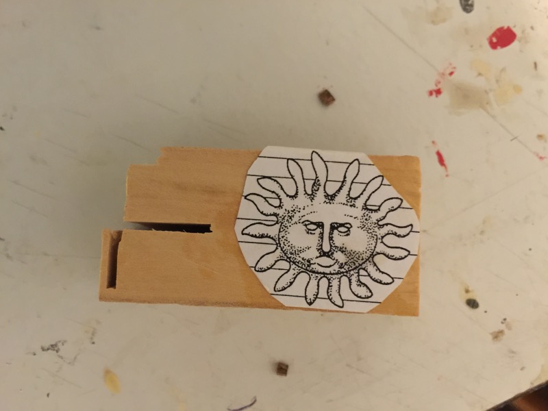
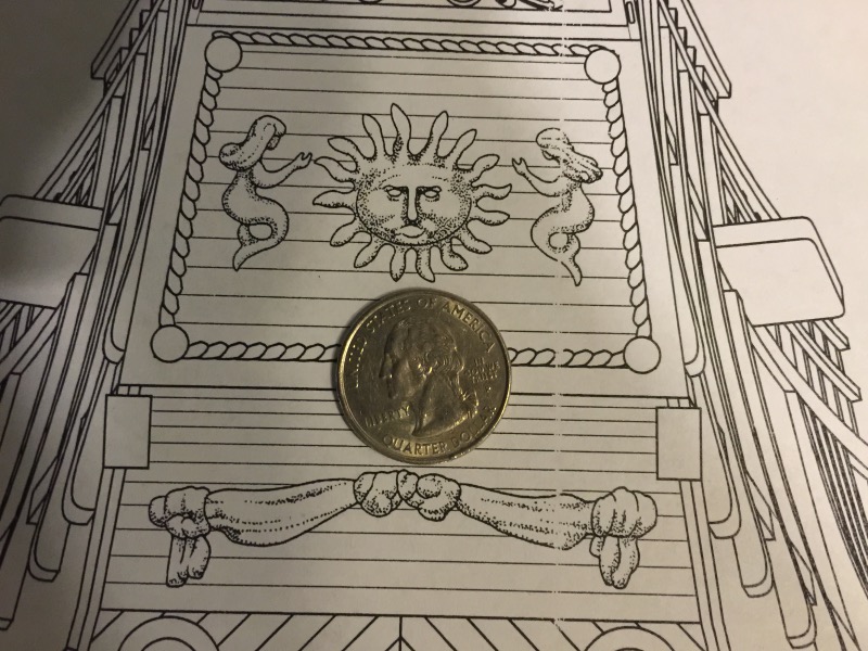
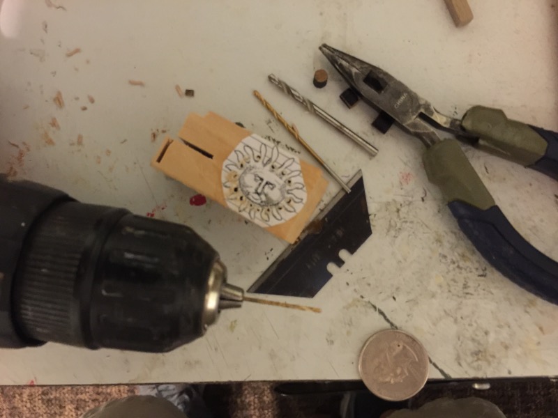
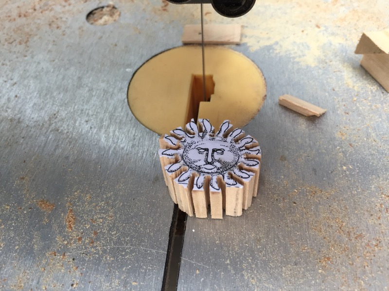
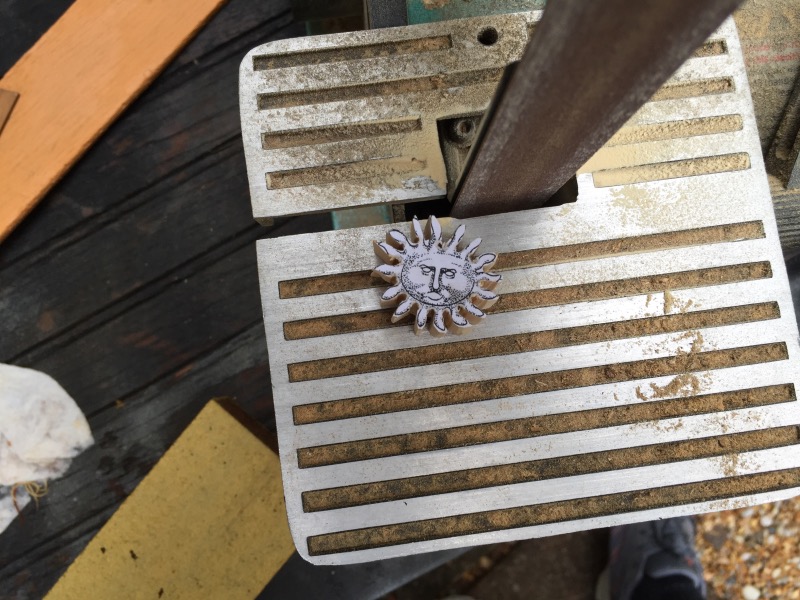
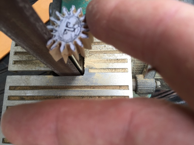
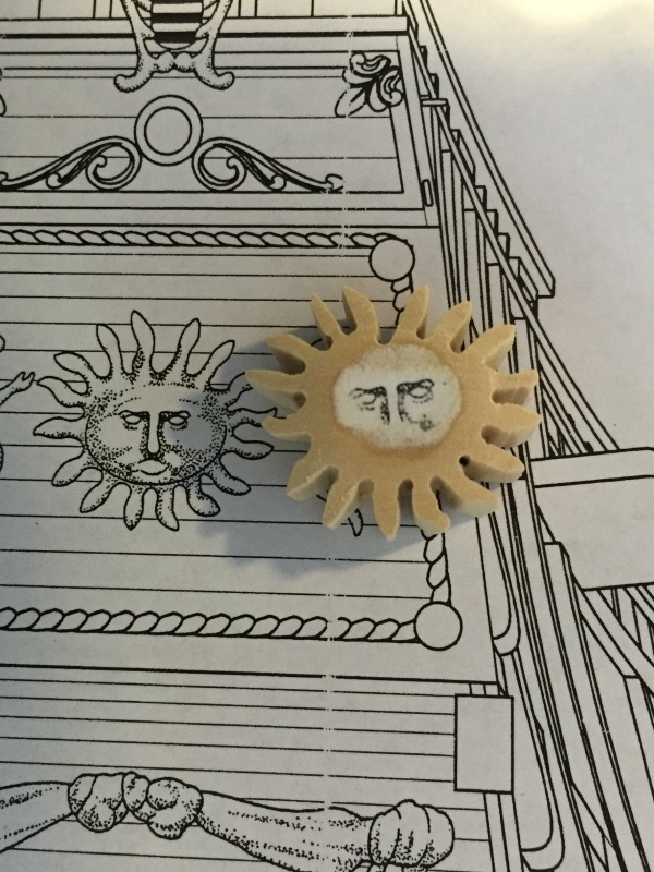
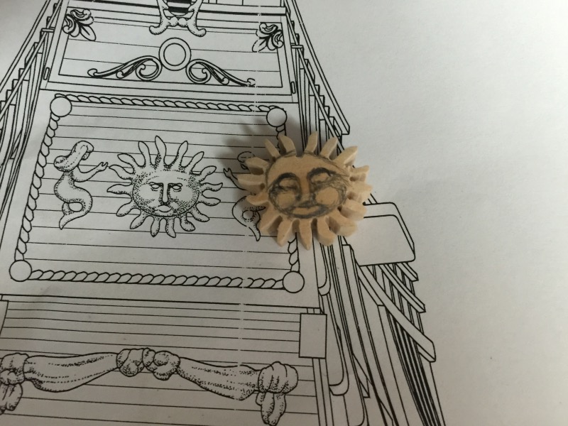
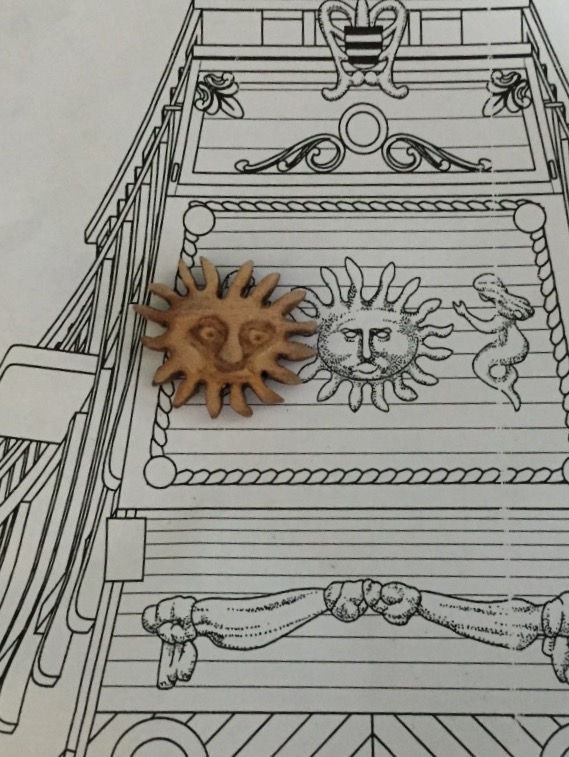
I am posting my attempt at carving. The kit came with a laser cut sun, but I butchered it badly. This is my third attempt. I copied the image and glued it onto a piece on boxwood. Here a picture to show its size. I first drilled holes at the base of the sun rays. It seemed to make it easier to stop at the correct spot when band sawing. I used three sizes of bits. I then took out a little wood with a bandsaw. Then I shaped the sun rays with a small bench belt sander. I rounded the face. I tried to carve the face by using the paper as a pattern, but it didn't work. I ended up needing to draw the face. I cannot draw. The is about three hours in. And this is the final result.
-
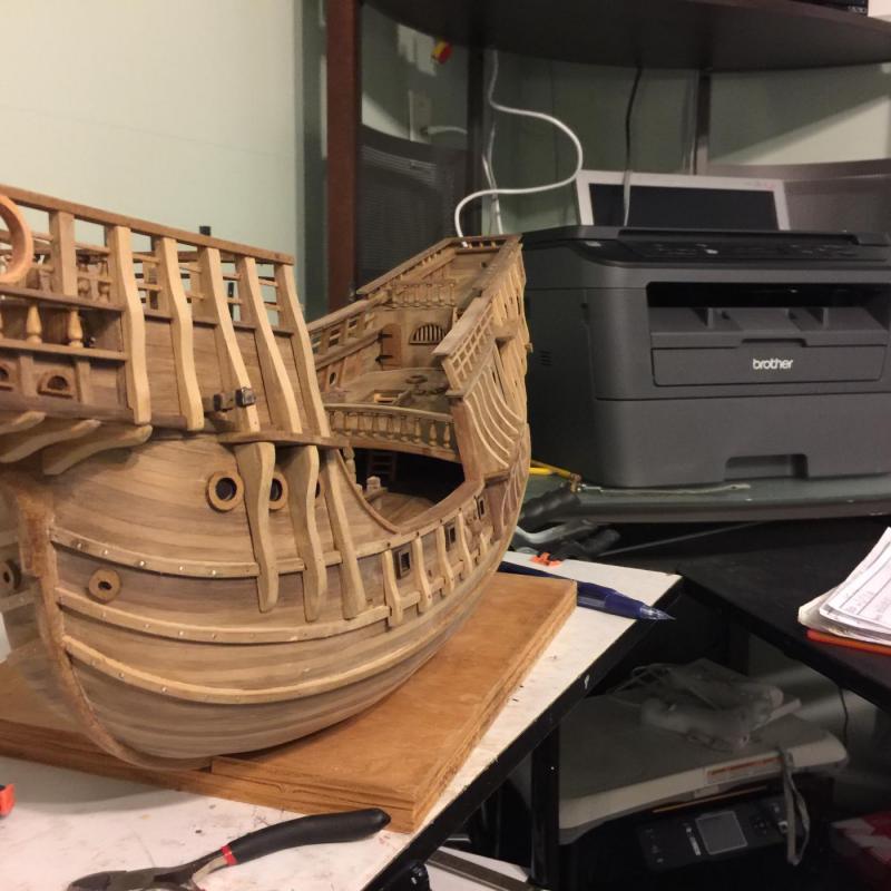
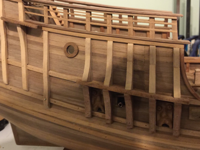
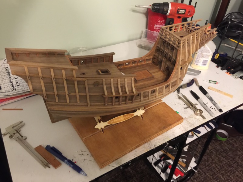
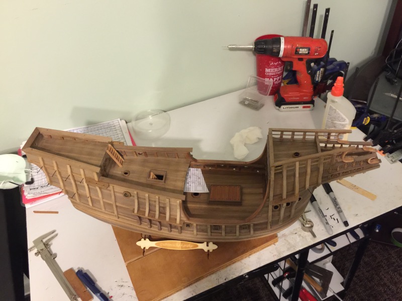
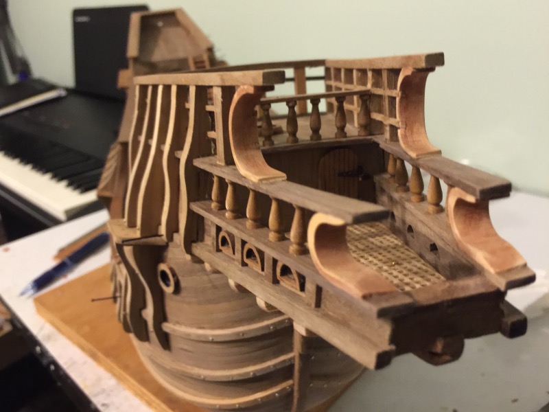
Ian, Frank, Don, and Red: Thanks for your kind words and for looking in on this log. Don, D-construction has happen a lot on this build. I have mentioned a few cases but not all. If one were to look back at the "in process" decking of the bridge deck and then look at the finished bridge deck, you could see that the hatch is in a different location. I'm still,trying to figure out where my head was when I was planning out this. I've finished all the vertical reinforcement timbers and finished the railing on the forecastle. I used a thicker piece of wood for this top rail with plans in my head for some added details later. Also, the middle balusters on both sides of the forecastle railing are not supposed to connected to the vertical reinforcement timbers. Again, this is part of plans to a few added details later. I'll point out this change below in the pictures. These first two pictures show all the progress as a whole. The two small horizontal rails below the thicker top railing is supposed to be attached on the outside of the balusters as it is on the backside of the forecastle railing. On The left and right sides you can see I've inset the small horizontal rails on the inside of the balusters. This was needed because of changing the shape of the balusters. The picture below better shows the inset small rails. Also notice the five vertical timbers. The plans show only the first and fifth vertical timbers and balusters as one piece. As you can see I made all five as one piece. The curved pieces are also different. The plans show these pieces being curved 90 degrees where I cut them with a 180 degree curve. This pictures shows the thick upper rail. I used a piece twice as thick as the plans called for. There is absolutely nothing wrong with the plans as they are. All of these little changes are just me chasing wild ideas.
-
I just read through the ten pages of your build log. You are a top level craftsman. Great work.
- 191 replies
-
- 3
-
-
- victory
- caldercraft
- (and 1 more)
-
I need to repost the first picture in the last post. It seems to have been cropped.
-
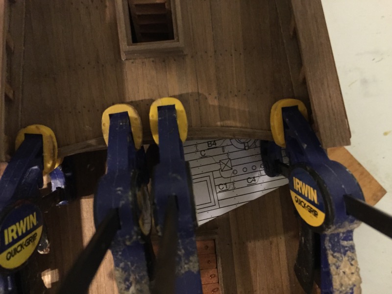
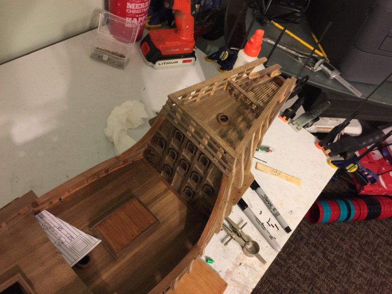
The building continues but at a slow pace. I'm still making the vertical reinforcement timbers. These pieces go on the forecastle. I needed to remove a vertical piece I had attached earlier. You can see the scuffed planks at the front edge of the forecastle. It is alway "fun" trying to figure out a way to clamp each piece. I also needed a curved piece. I tried to make it out of walnut, but the walnut kept snapping. I had some boxwood. I'm always amazed at how easy It is working with boxwood. I made one piece wide enough for the two pieces I needed. And then cut the two pieces to the size I needed. Here's how it looks now