HOLIDAY DONATION DRIVE - SUPPORT MSW - DO YOUR PART TO KEEP THIS GREAT FORUM GOING! (Only 20 donations so far - C'mon guys!)
×


Srodbro
-
Posts
299 -
Joined
-
Last visited
Content Type
Profiles
Forums
Gallery
Events
Everything posted by Srodbro
-
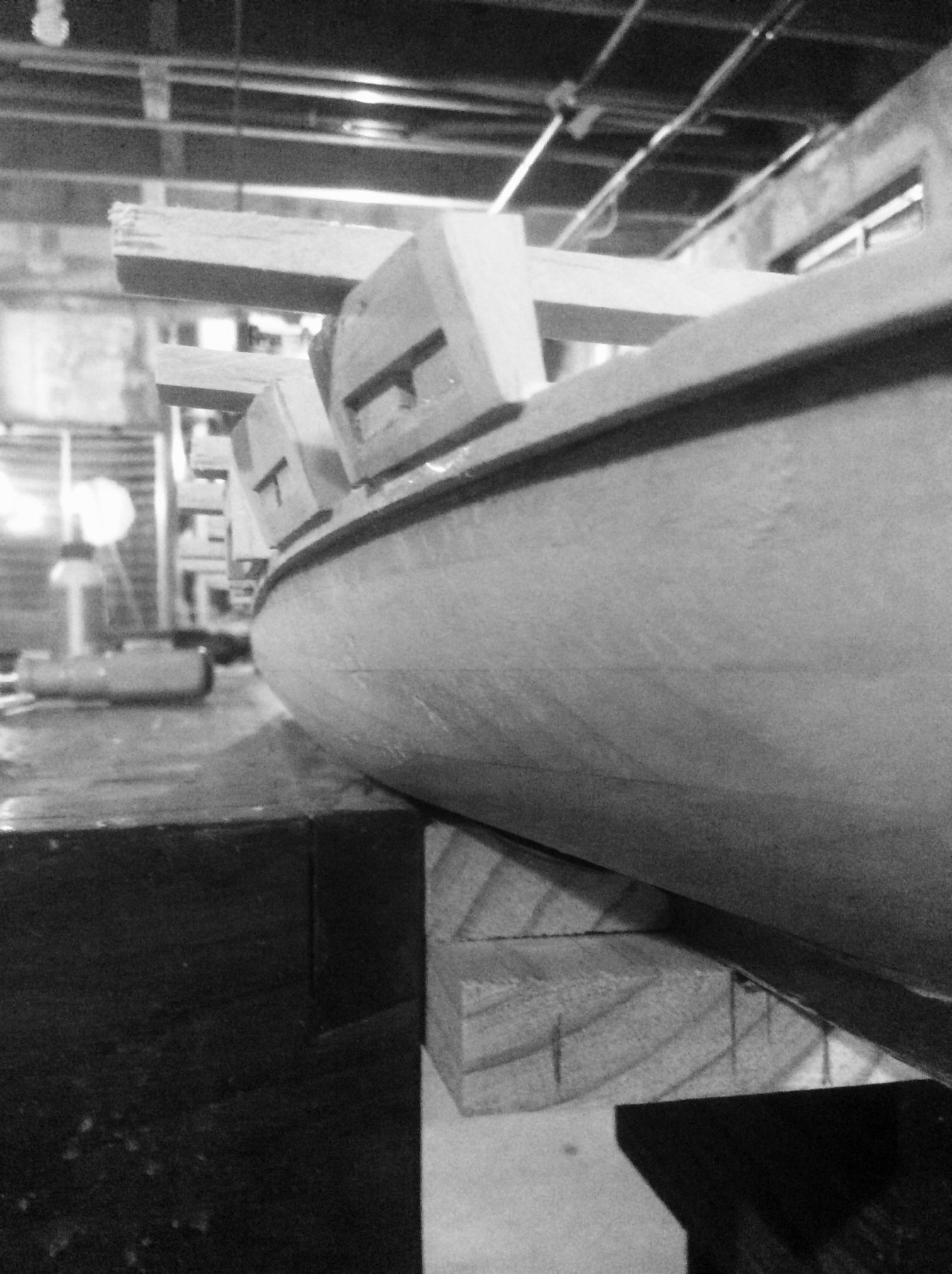
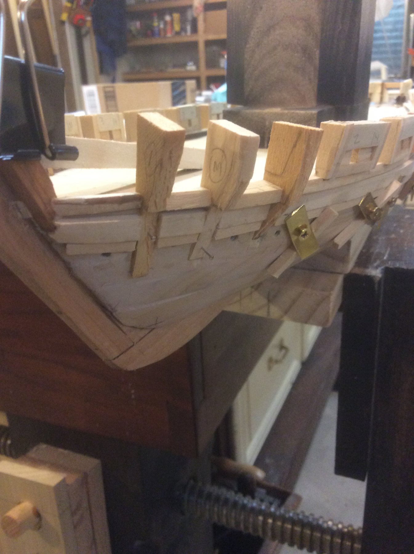
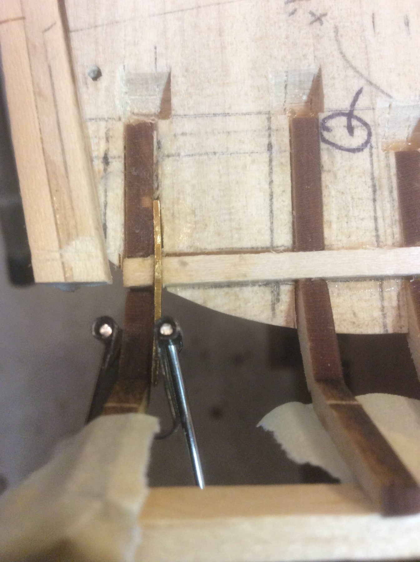
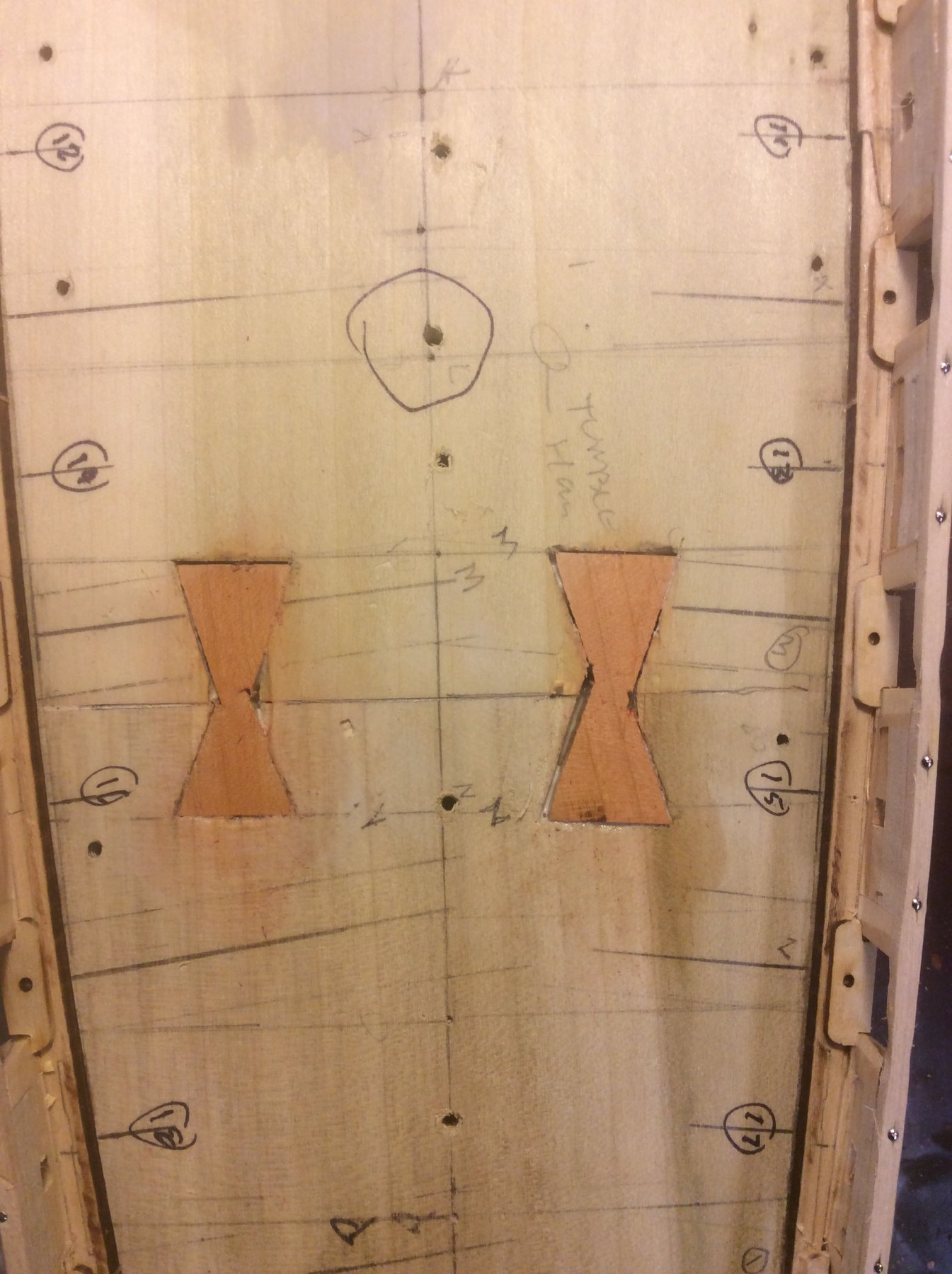
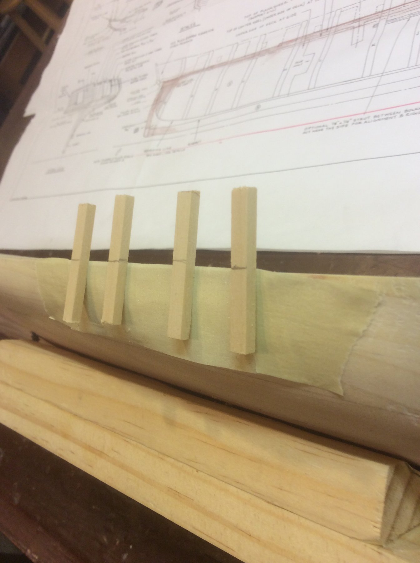
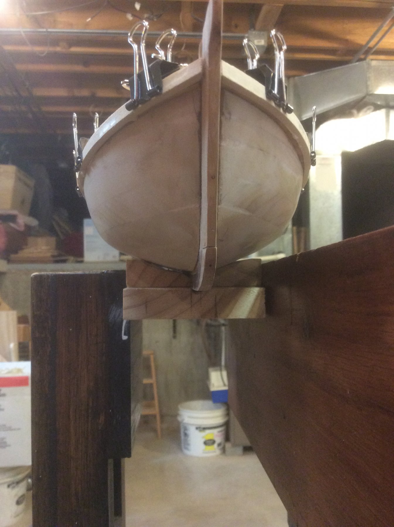
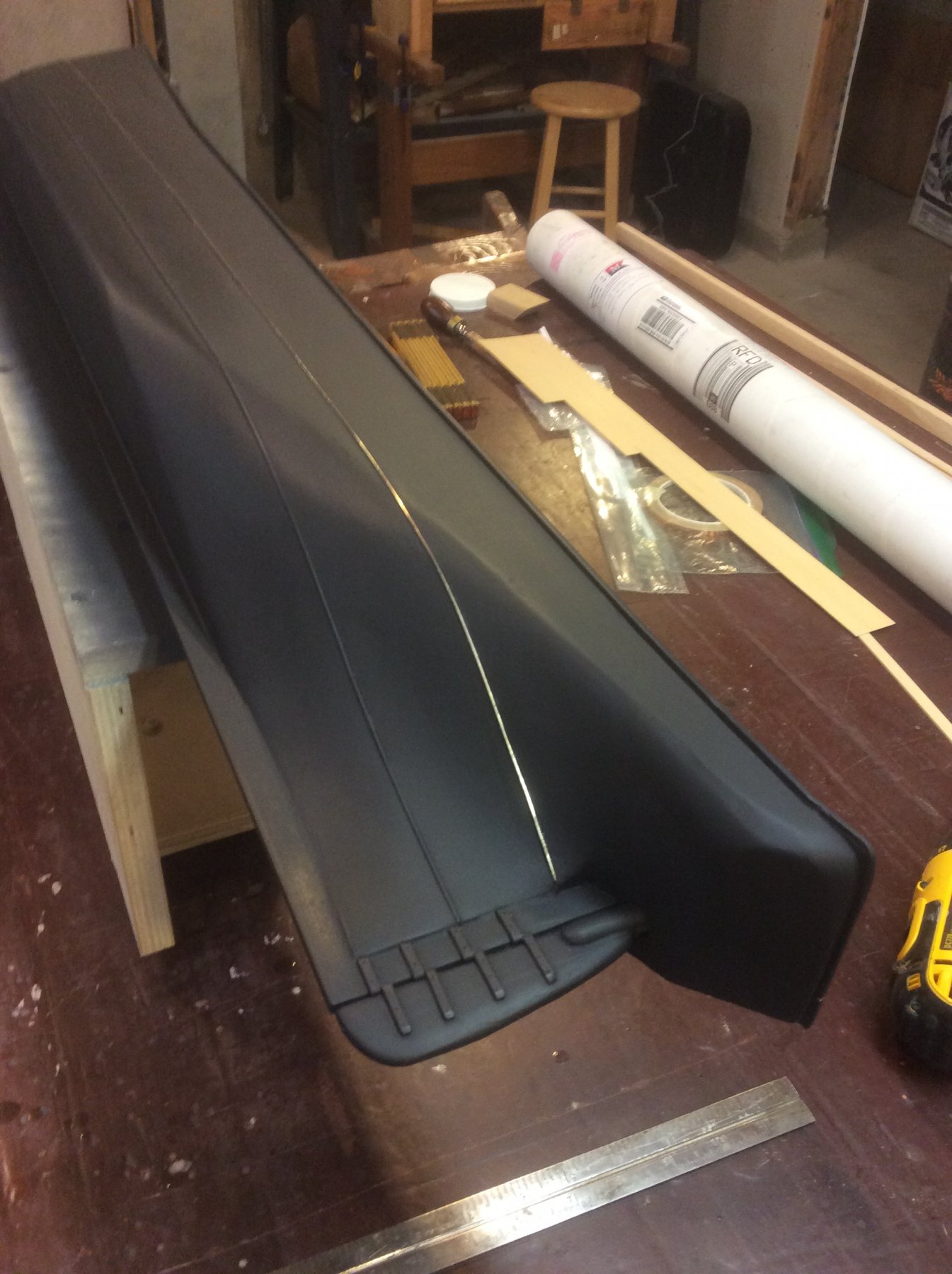
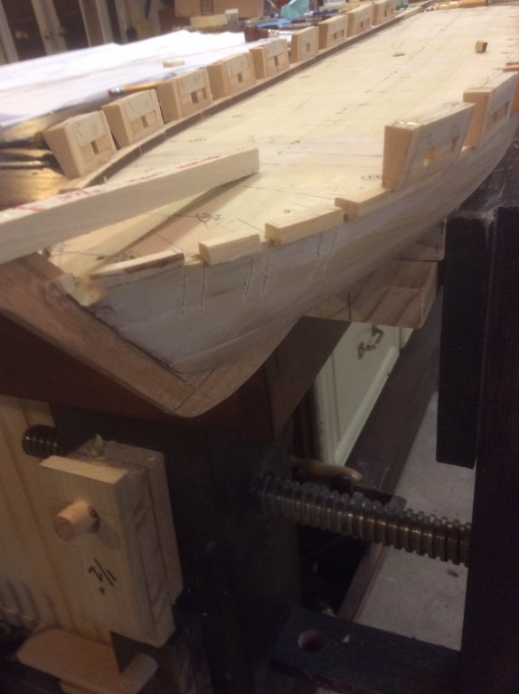
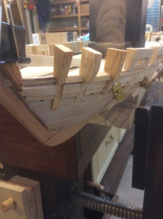
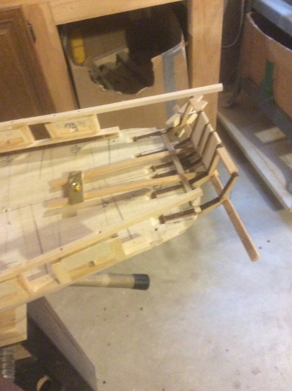
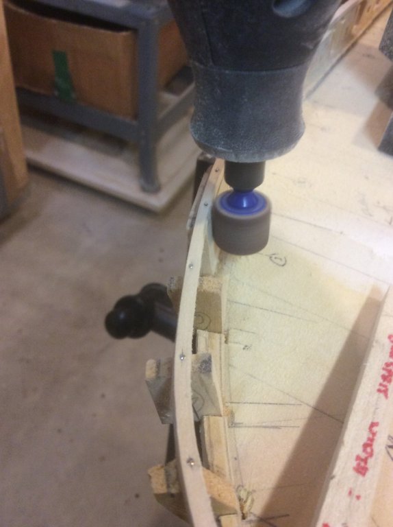
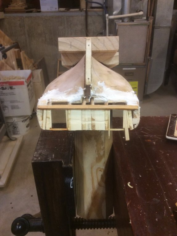
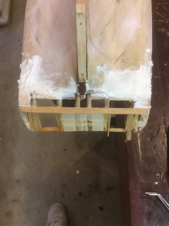
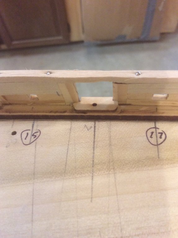
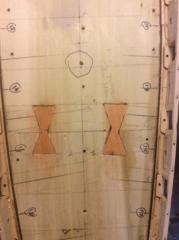
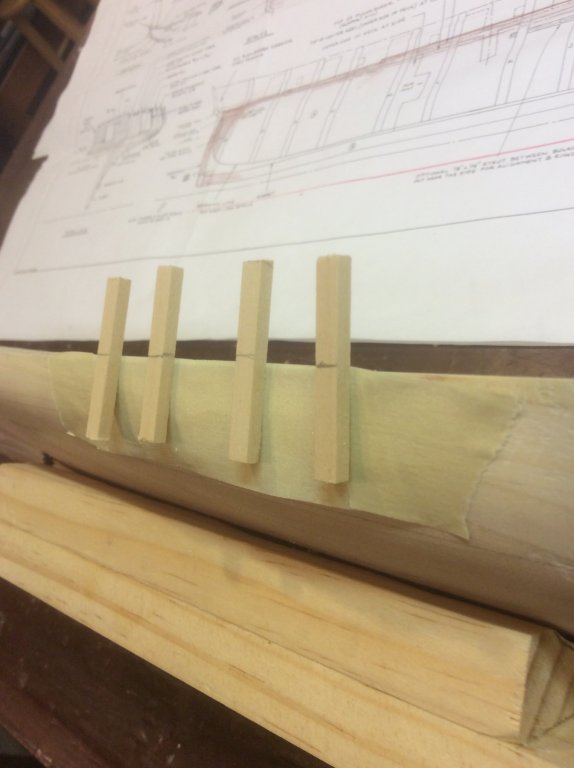
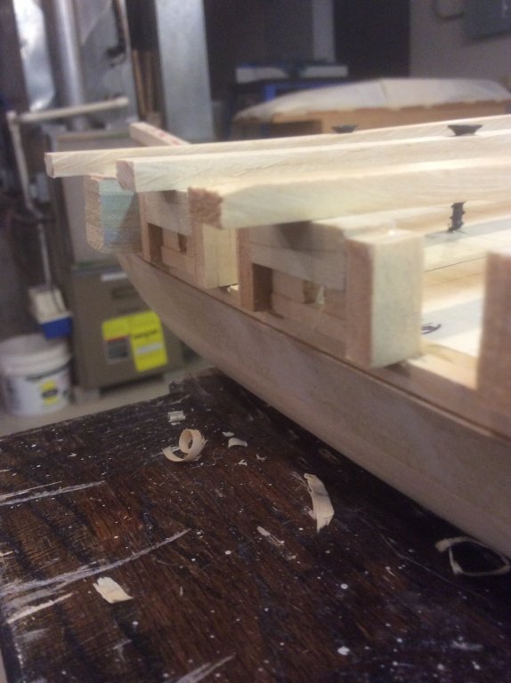
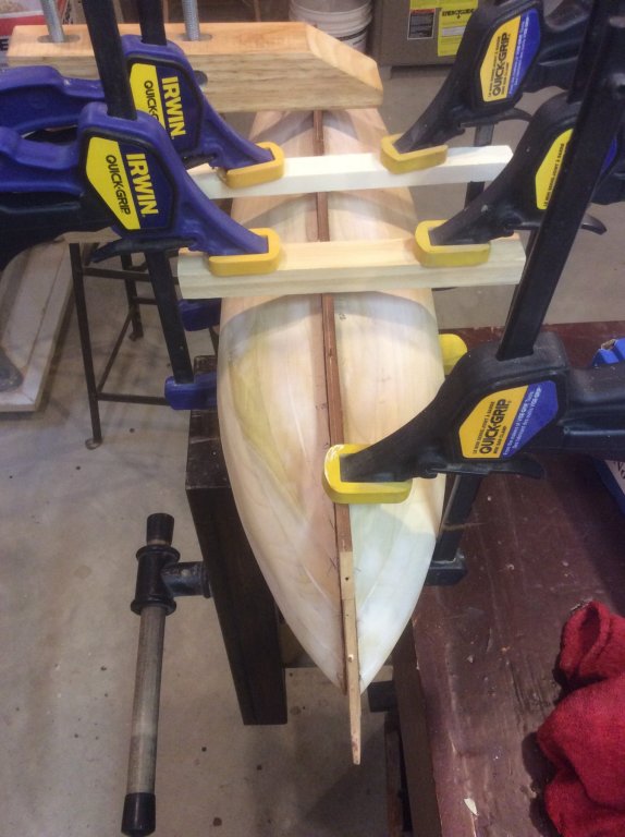
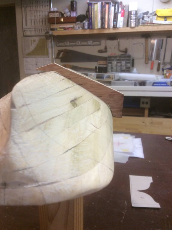
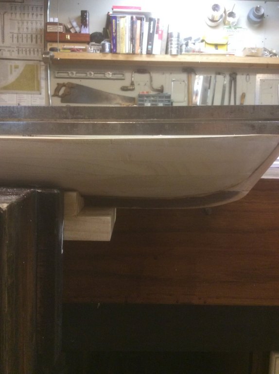
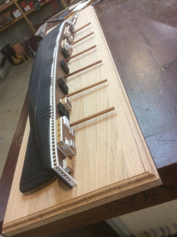
This black and white image of the hull from below the deck level looking aft highlights the relationship between the bulwarks and the waterway extension, and the hull. The portion of the bulwarks that extends outboard of the waterway extension will need to be removed, and the hull built outward. Here the grooves for the bow timberheads and knight heads have been begun. Next, the rough timberheads added, and a couple rows of wood strips added to build out the hull (to address BM#3--over-zealous hull shaping). Using the kit's laser cut rails, I laid out the lines on top of the forward timberheads and the bulwarks that would be used to shape them. Before continuing with shaping, the stern needed attention. Because the top of my solid hull is equal to the underside of the future deck, insets needed to be cut and chiseled out to set the stern stanchions flush with the hull. it didn't take long before these delicate pieces broke. If I ever do this again, I'll fabricate the stanchions of laminated styrene (seems like with all the builders who experience problems with these, kit manufacturers might consider furnishing these in Britannia metal). The port outer stanchions broke later. I repaired and reinforced the broken ones with slivers of brass, CA'd into place. After framing up the stern, the topmost element of the bulwarks, a continuous strip from bow to stern, was soaked, pinned and glued into place. the final bulwarks just forward of the stern were fabricated similar to the typical bulwarks subassemblies and glued into place. Then all the bulwarks were addressed with the Dremel tool. With filling and sanding, she was starting to look like a ship. Remember BM#1?(Big Mistake #1 -- not having a clear understanding of the stern). Well, that's coming home to roost, now. My guessing at the shape of thing aft of section "Q" required a lot of filling with wood and filler. The space between the sternpost and the archboard should get covered by about 5 or 6 planks. I only have room for about three. by the way, I haven't seen on any build log an "arch" in the archboard anywhere near that shown on the kit drawings. Mine certainly doesn't. I'll bet it has to do with the positioning of those darned stern stanchions. I may have to live with this stern inaccuracy. After another round of sanding everywhere, I turned to installation of the sheerplank. These laser cut kit pieces had cutouts for the bulkhead timberheads, which I don't have. So, I only used that portion of these parts that go into the gunports. And "Boo-Yah!!" I think I'm ready to start planking, now! No, just one more thing to do. Remember BM#2, where I glued up the hull lifts? The stern 1/3 of the upper four lifts were married to the forward 2/3 by a glued butt joint of end grain. So, I cut into my hull and added two butterfly splines across that joint. Now I can rest easy that it is less likely to fall apart until the deck planking can help marry these two sections. So, with BM#2 addressed, as well as BM#3, and BM#1 at a (maybe) acceptable state, this Niagara is going into mothballs for a few months. Next week starts late summer and fall fishing season, followed by hunting season, followed by the holidays. Many more activities for this old man to do while he can. But, I can't be in the boat all the time ,nor continually traipsing the wilderness for game, so maybe I'll get around to making the small boats in the kit, or cannons, or I may just lop off that stern, aft of section "Q". Or, who knows: I have all the kit hull components I need from the kit to build another hull, and demonstrate to myself that the solid hull experiment, vs. the plank on bulkhead, while interesting, was much more involved than I thought. I may wind up with Niagara AND Lawrence.


-
Master and Commander: The 24 minutes of deleted scenes.
Srodbro replied to uss frolick's topic in Nautical/Naval History
I've thought it would be neat to have a movie (or a book, even better) that began, oh, thirty years earlier and ended in "THE MUSIC-ROOM in the Governor’s House at Port Mahon". -
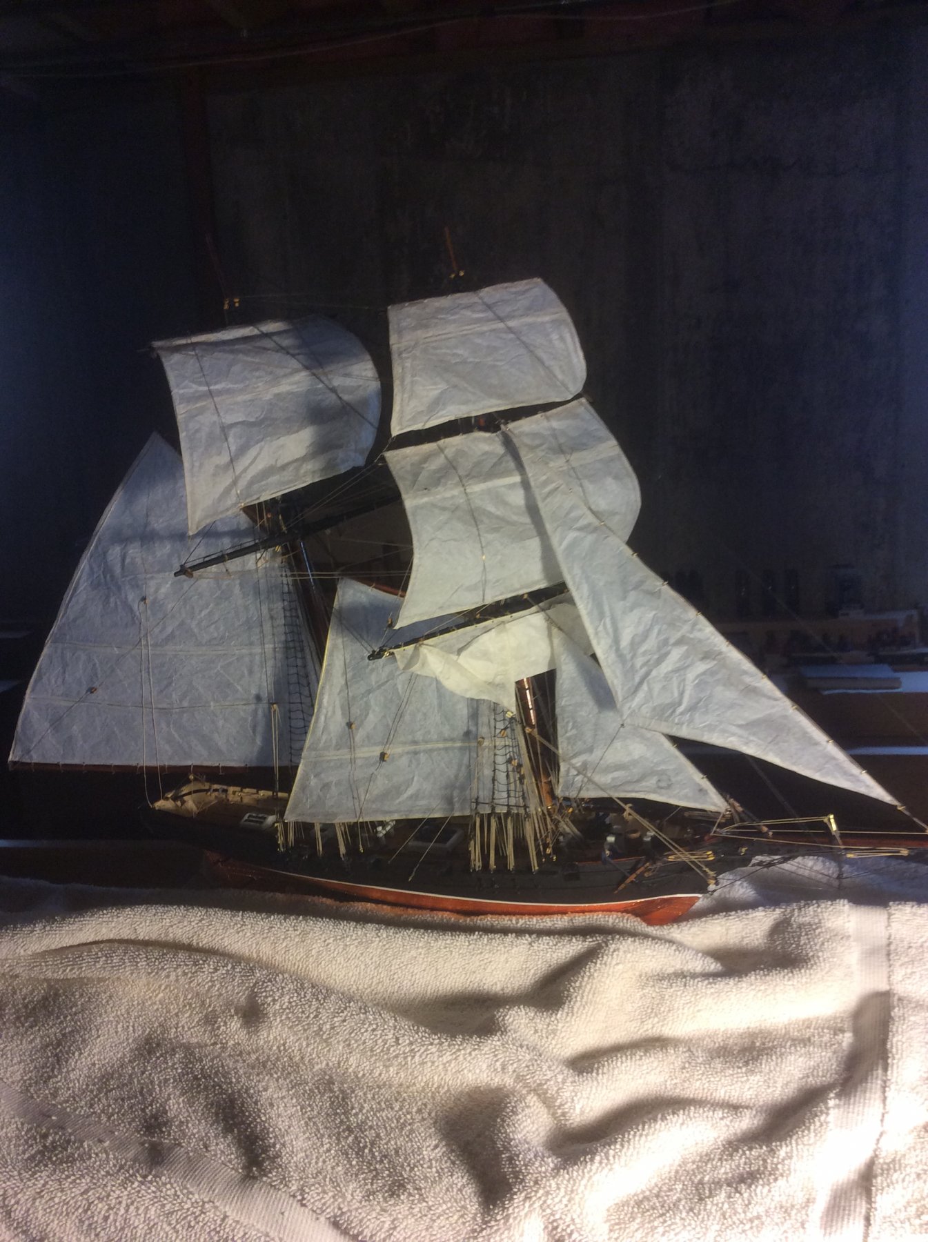
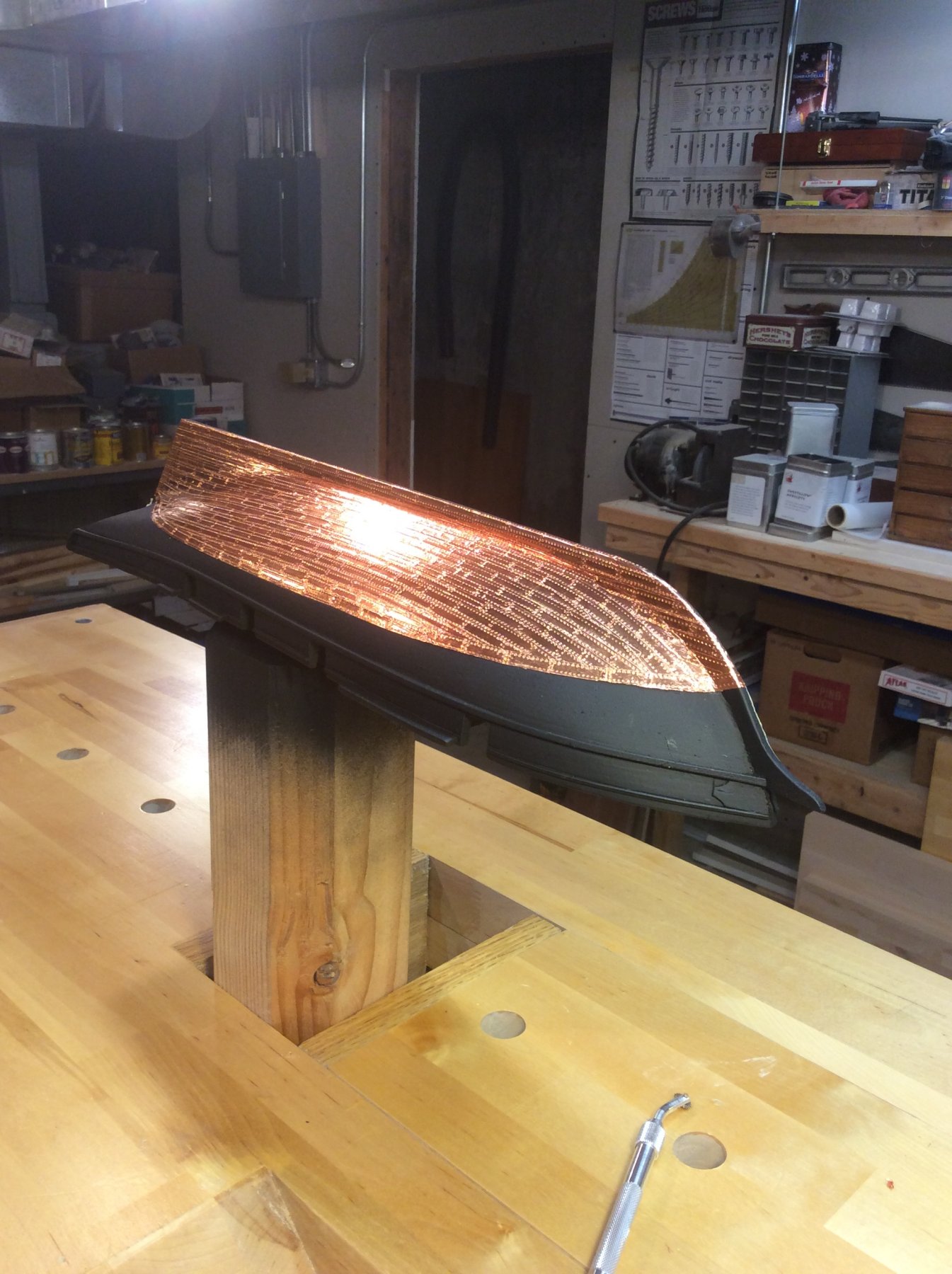
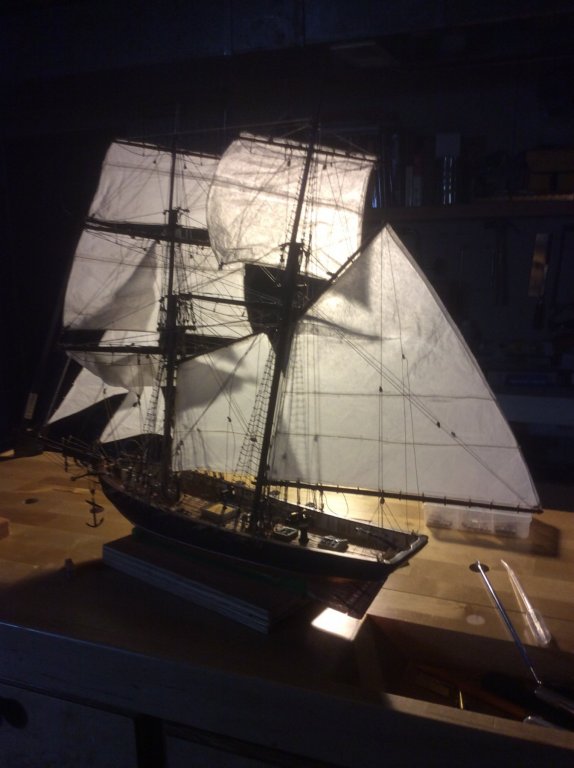
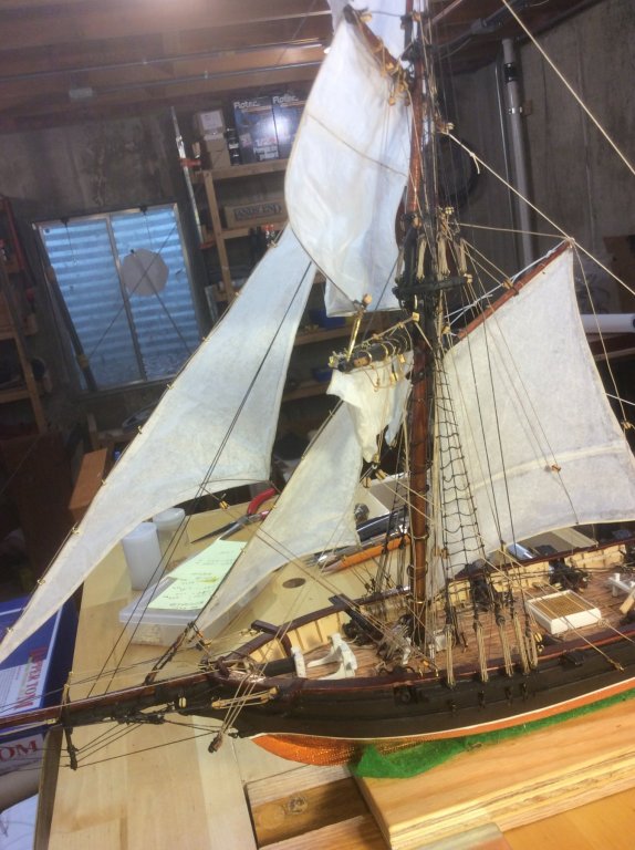
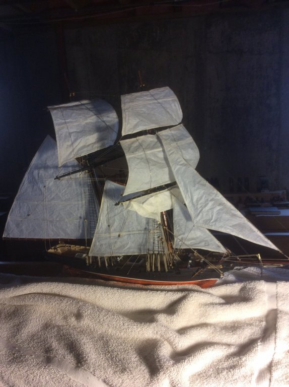
I have made sails of tissue paper (the kind used in gift wrapping, not the stuff you wipe your nose with) attached to a bolt rope running the perimeter of the sail, made of fine (28ga) brass wire. The ends of the wire are doubled about a half inch and soldered together. On gaff-rigged fore-and-aft sales, and on square sails, I'll run another wire at one or two reef points, and on large square sails I might add bunt lines, all soldered together. Then I cut the sail paper material about 1/8th inch larger than this brass skeleton, saturate the sail at the brass wire with dilute white glue, and fold over. At the reef lines, I cut a separate strip of sail material and glue in a similar manner over the wire onto the sail. Then, lash to the yards, or attach to the stays, and complete the running rigging. The brass can be bent for the desired effect. Produces an effect that's acceptable to me. The construction is easily seen in the backlit pic below. Lit from another angle, it looks ok, too. I'll also use brass wire for the sheets of head sails to hold them out as if pushed by the wind.
-
I get some from Menards, as well. It is also known as tulip poplar. Woodcraft stores sometimes have it in a greater variety of sizes. The Woodcraft stuff is also drier, and frequently on sale. Beware: When you take the plastic wrap off the Menards stuff it can quickly warp or cup, depending on the ambient humidity. Id stay away from the Aspen. Much too soft, fuzzy ... I haven't found a good use for it (not even good kindling).
-
I've used poplar for one solid hull project and am currently using it for another. Similar source as yours. No problems. Don't know how it would work cut down for planking. I know it paints well, but not sure about staining -- it has a variety of strong grain colors.
-
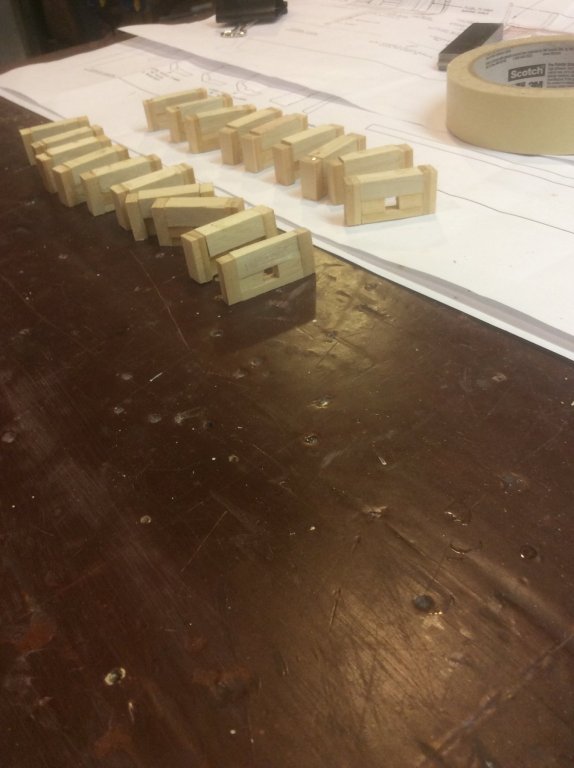
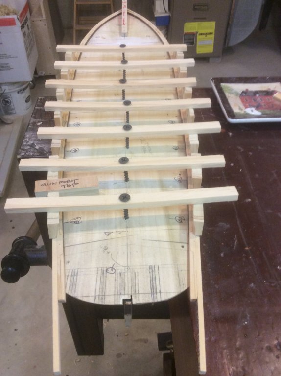
Not sure how that last pic got out of sequence but it shows the eighteen typical bulwarks subassemblies ready for installation.
-
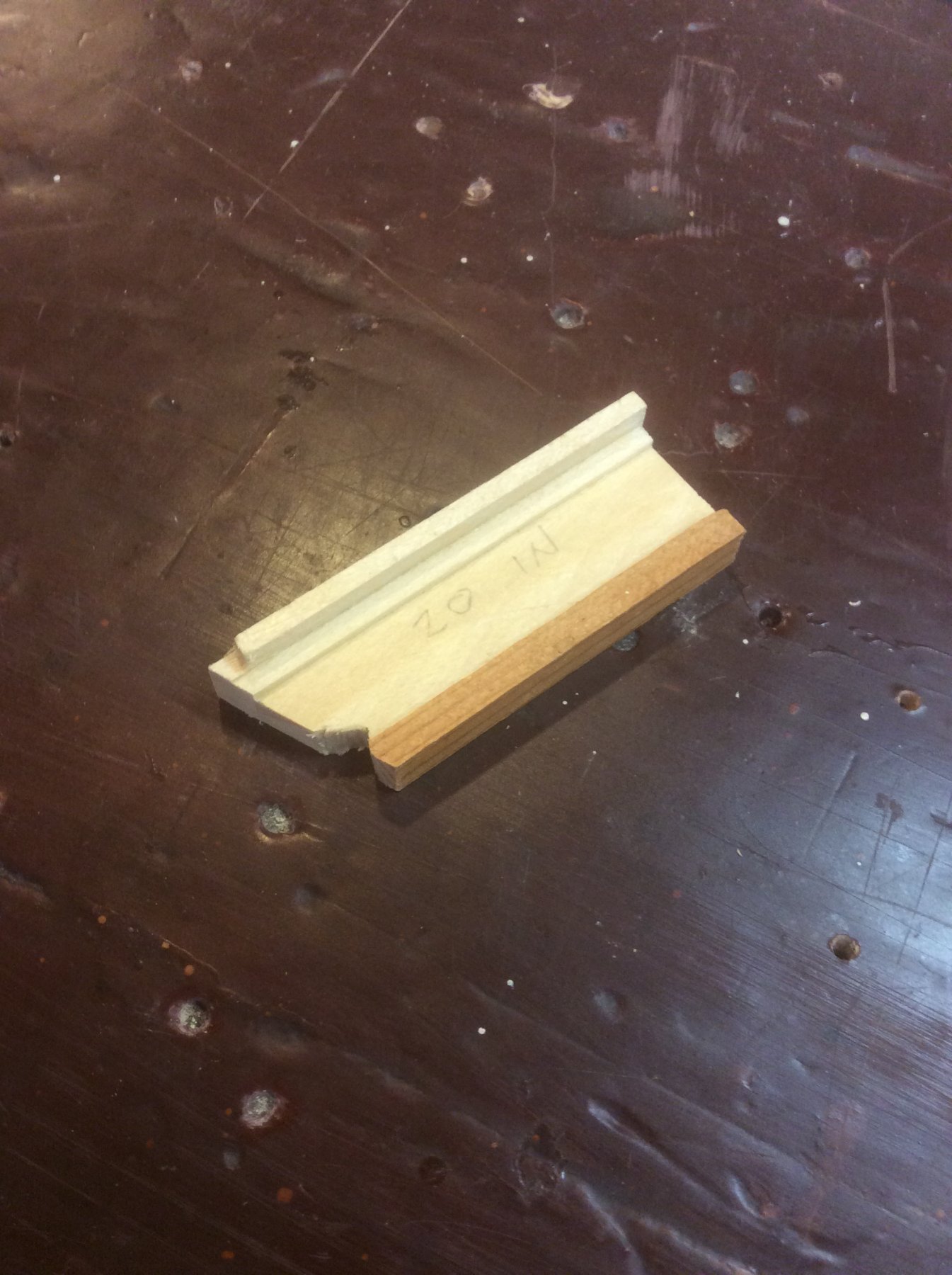
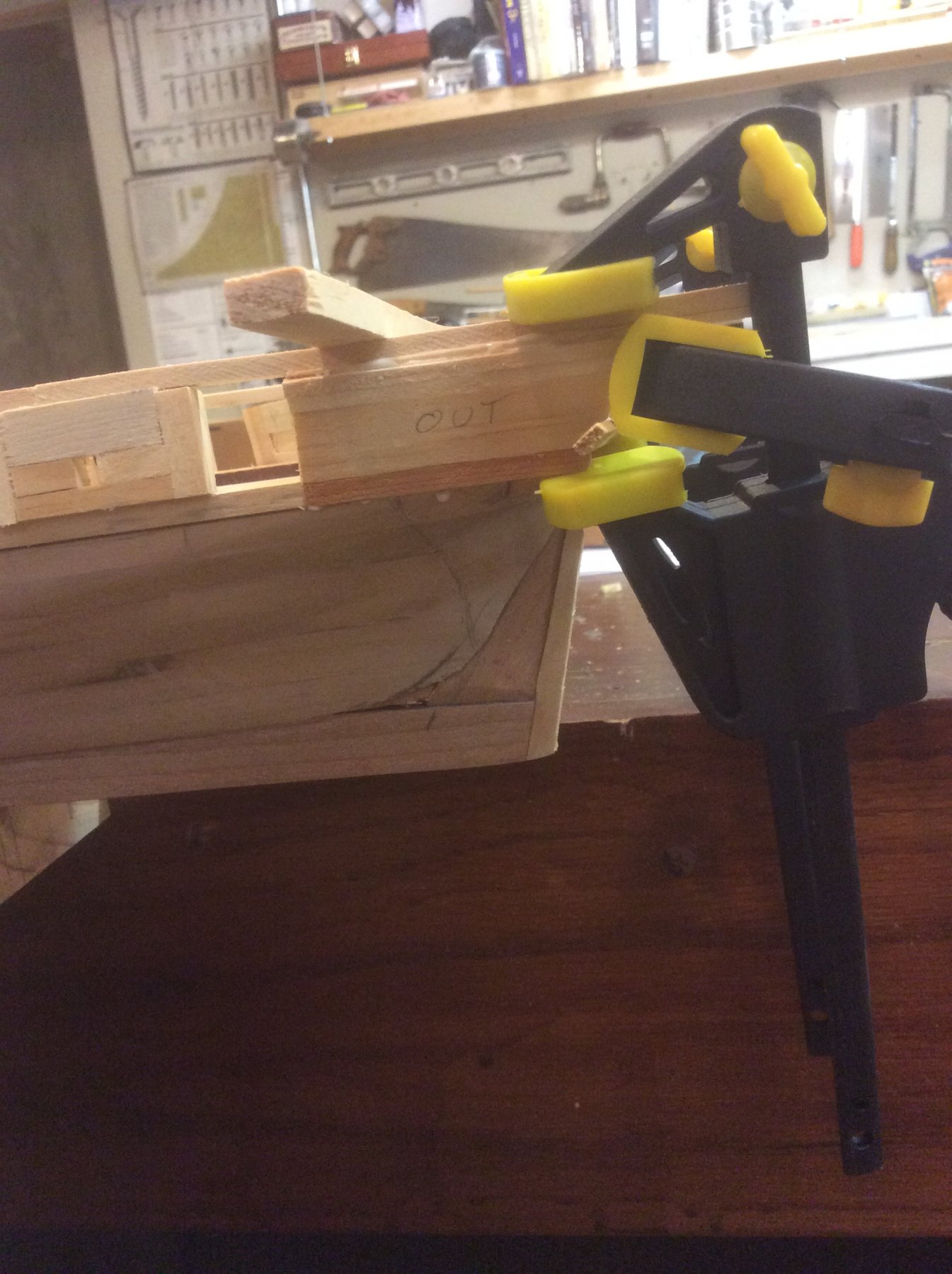
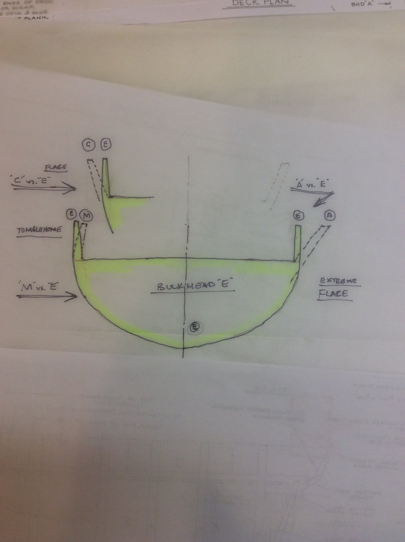
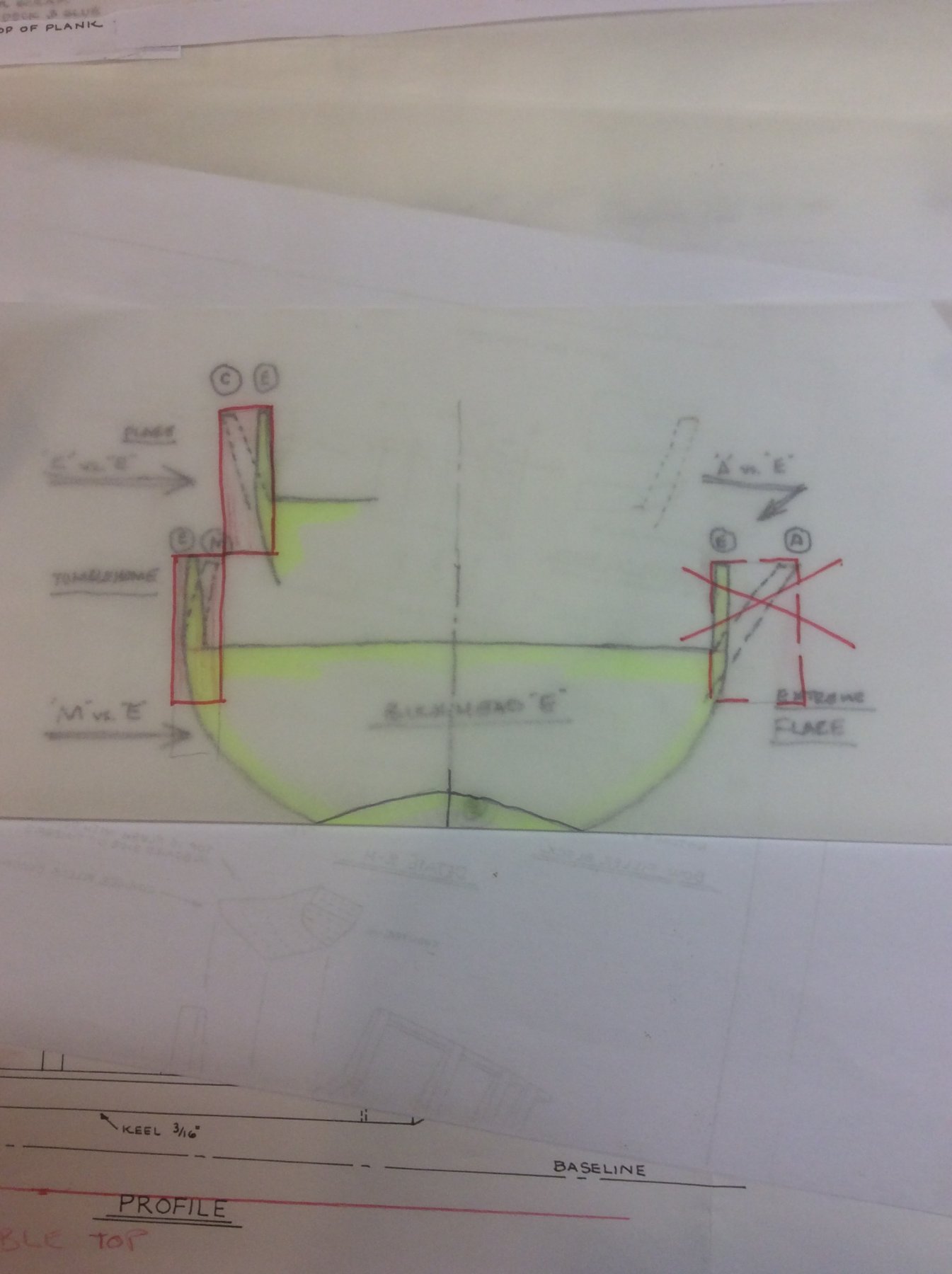
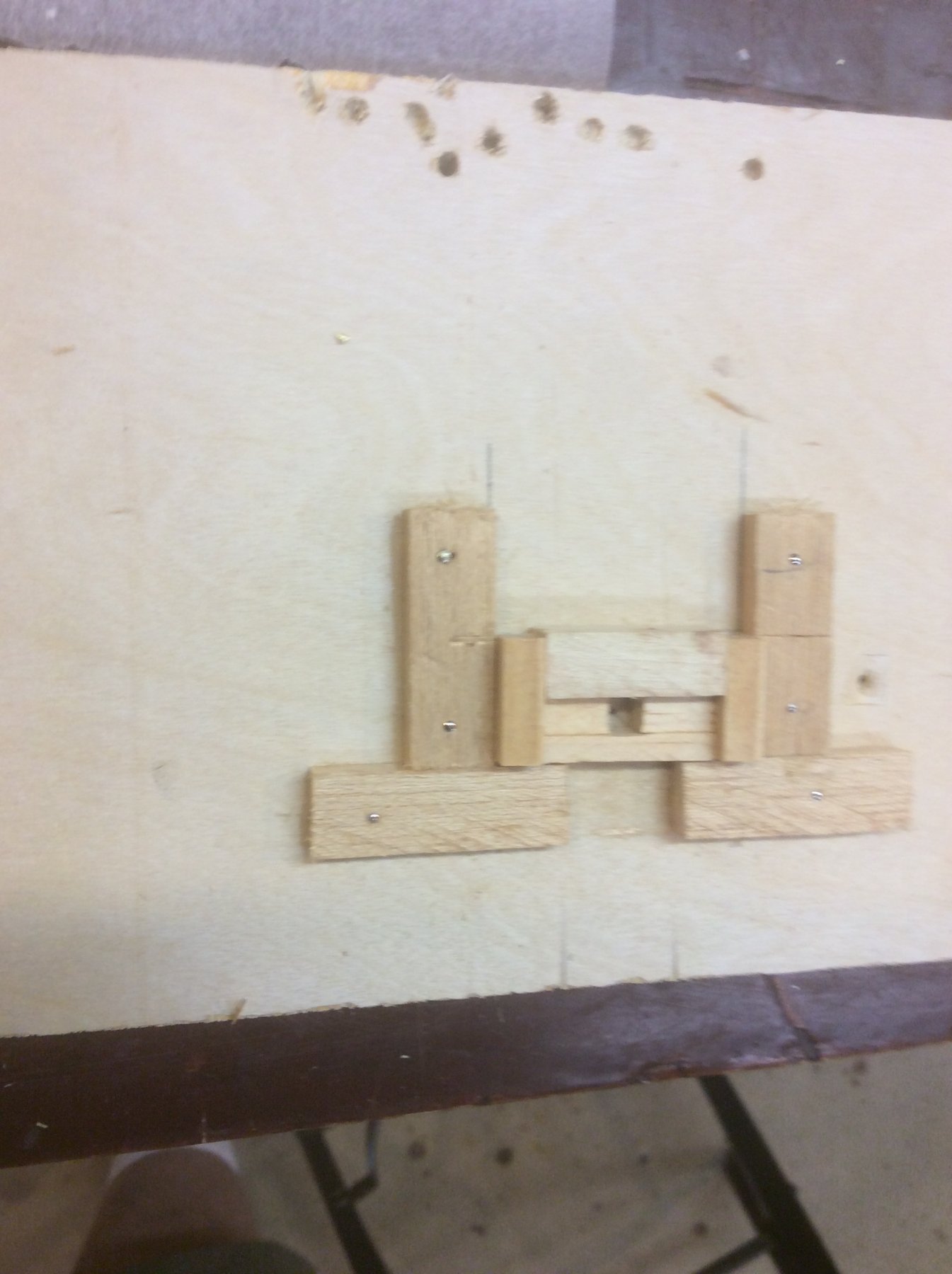
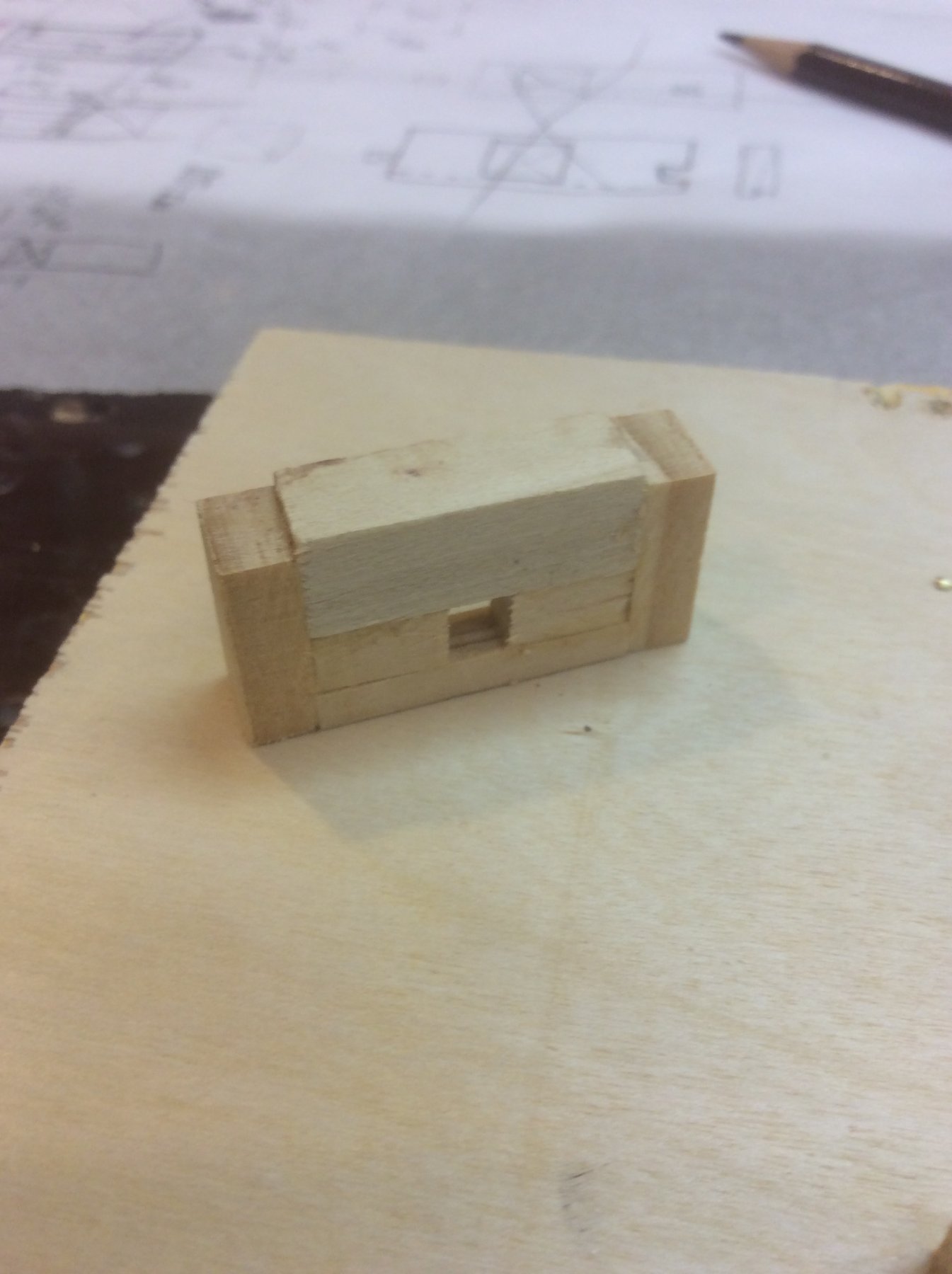
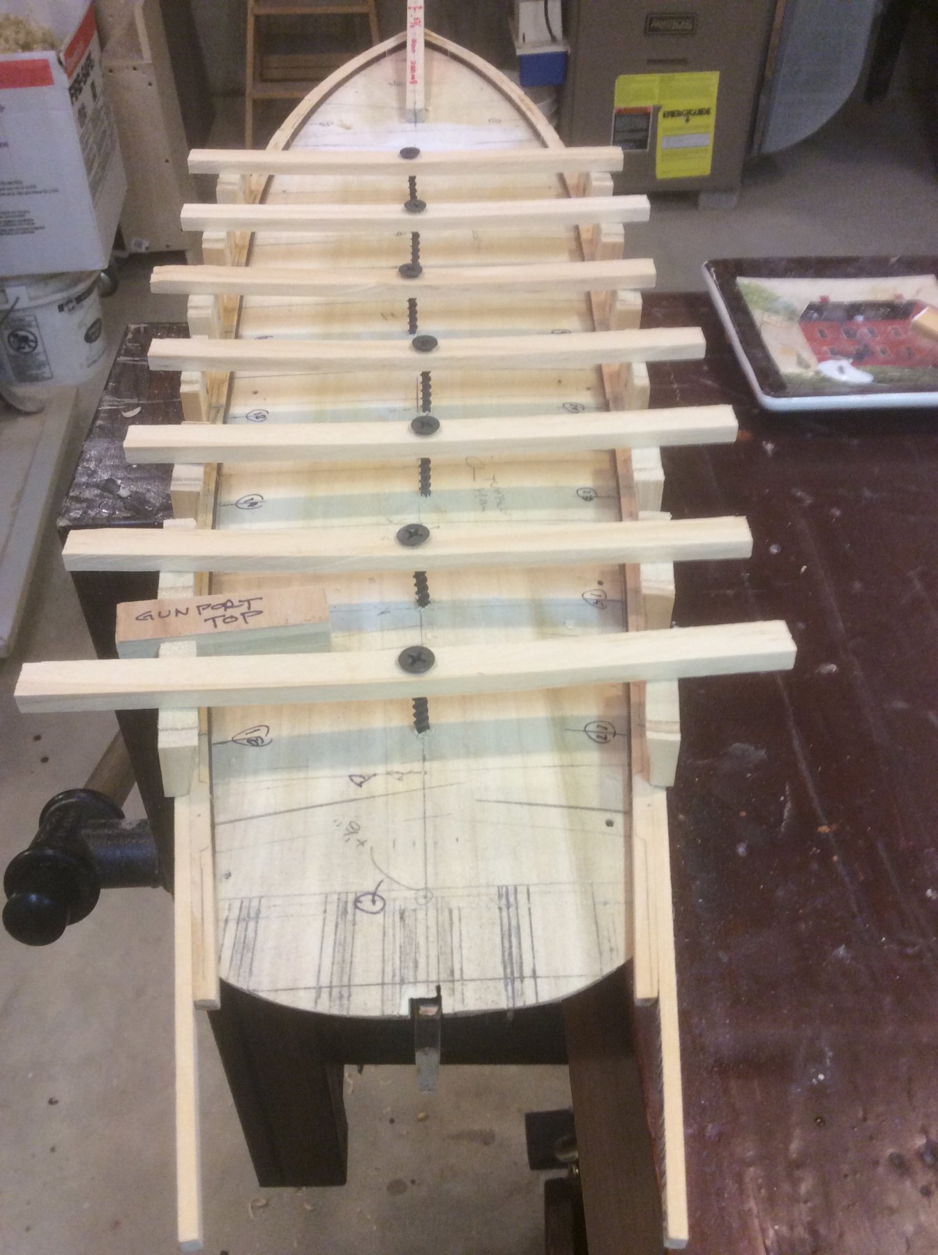
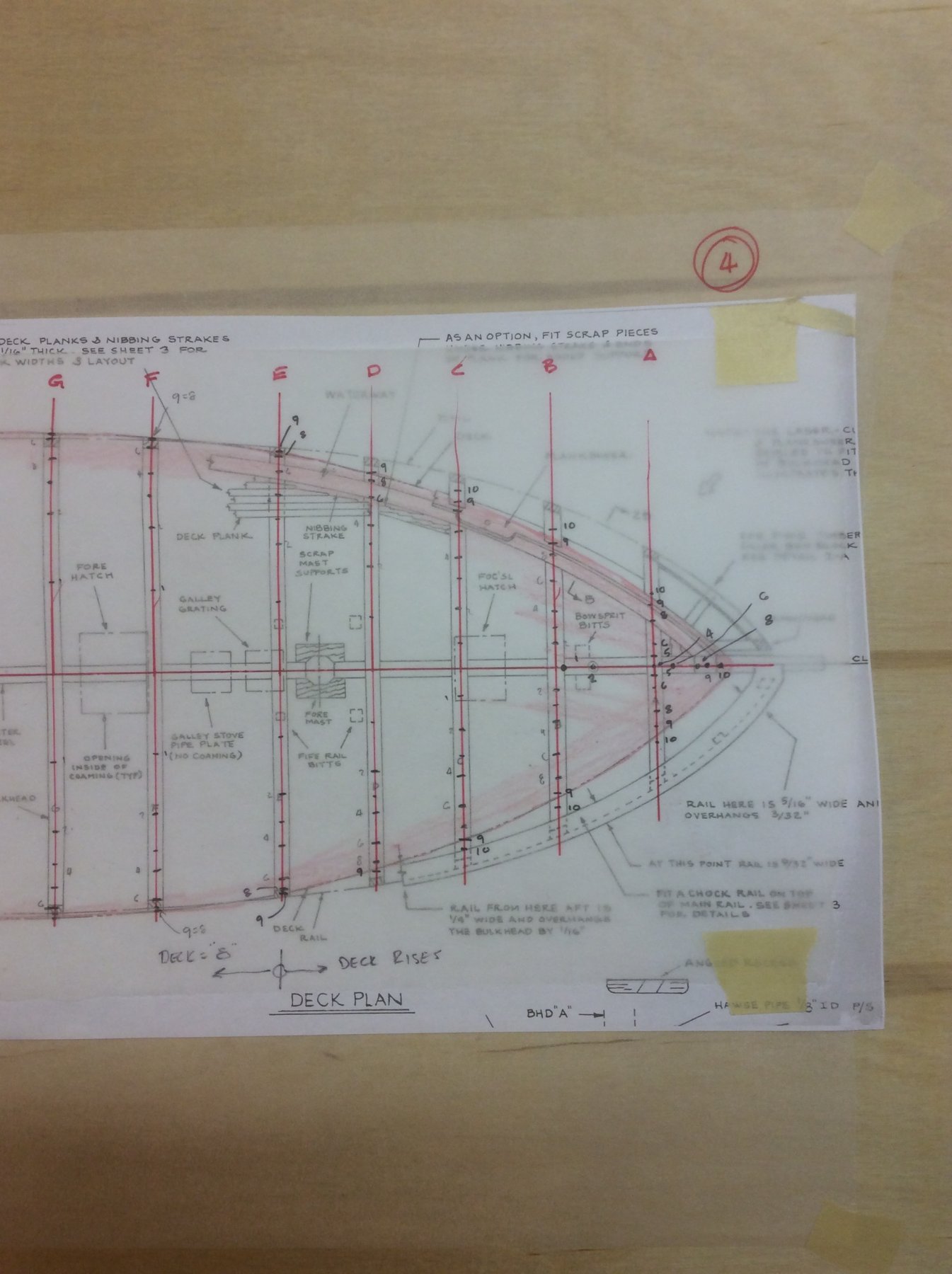
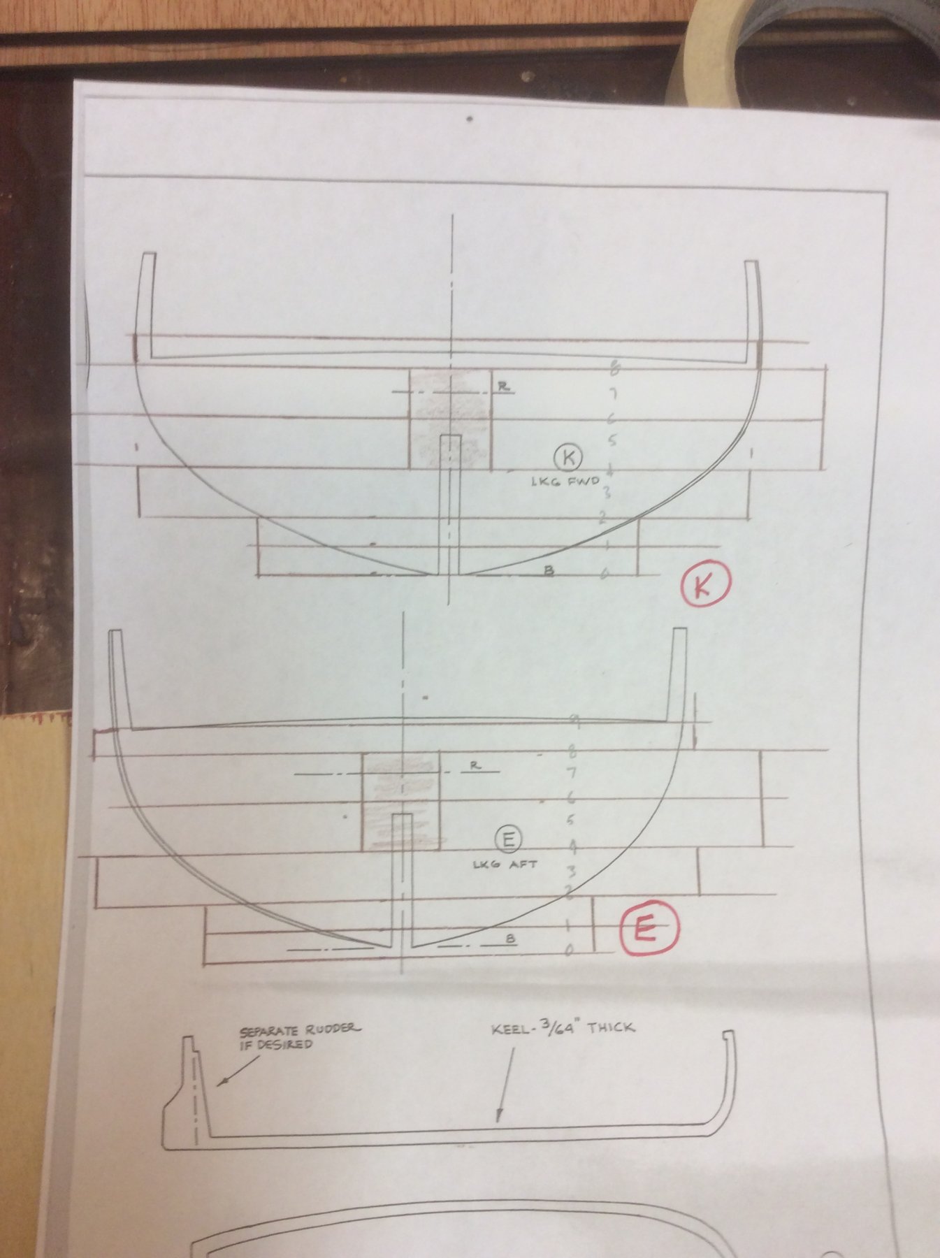
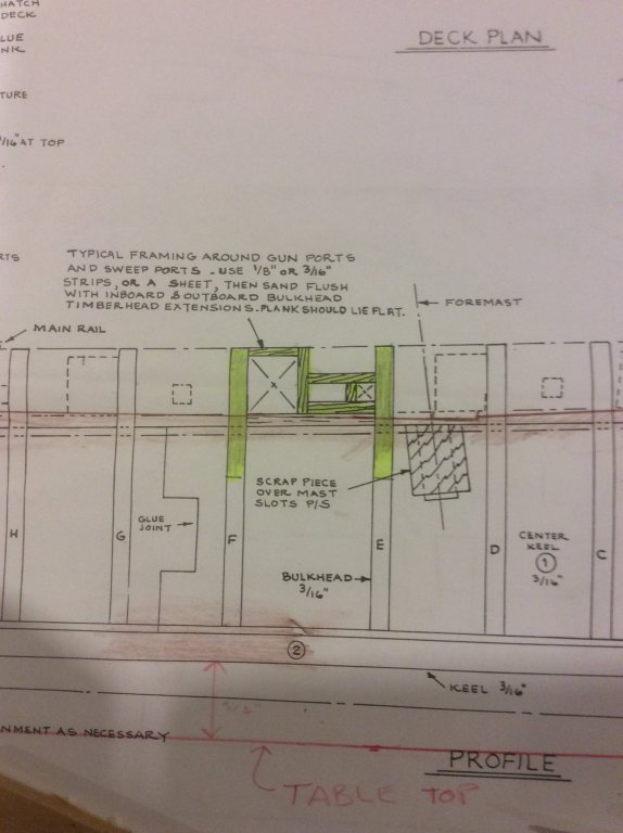
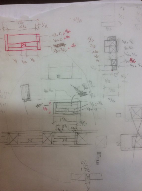
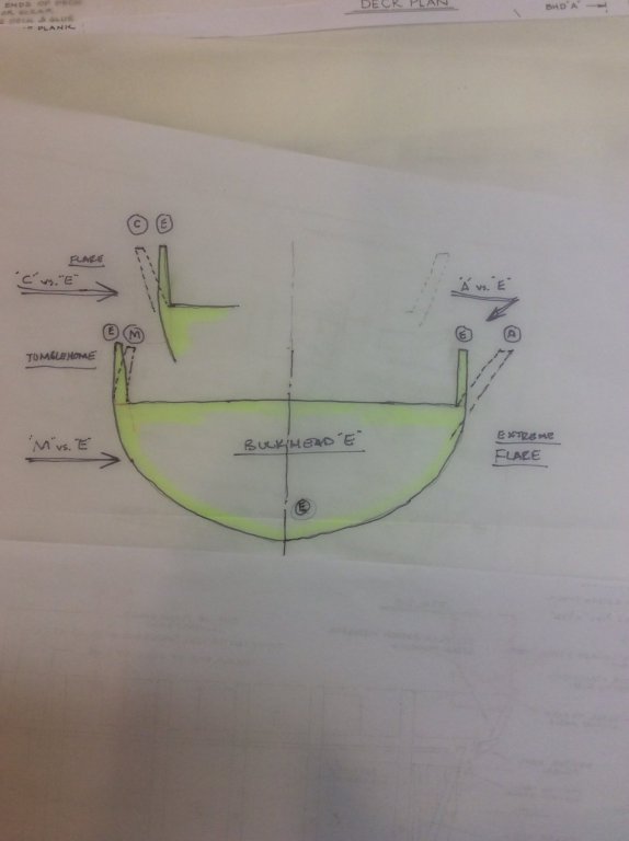
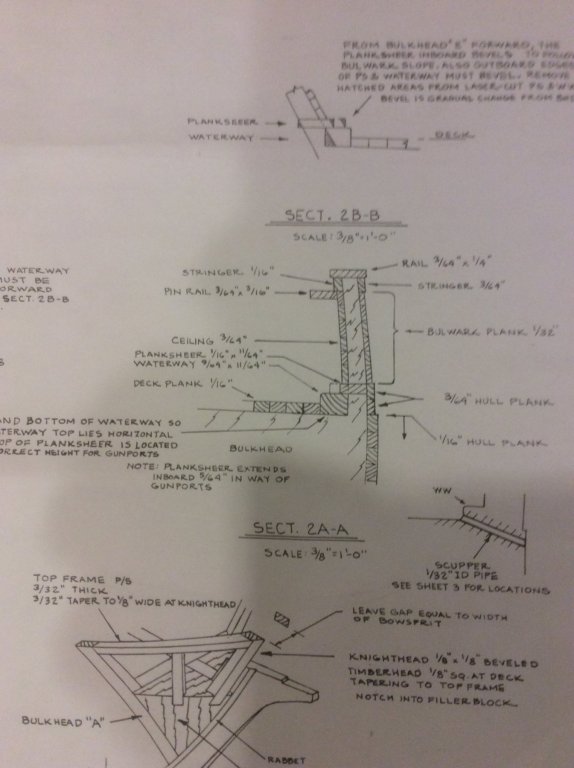
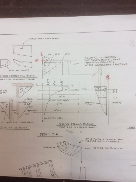
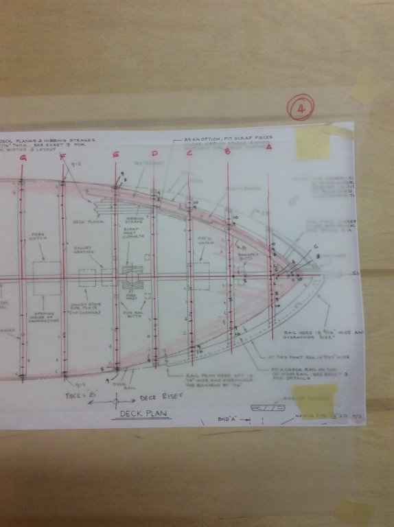
My excessive planing of the hull near the bow is my Big Mistake #3 (BM#3). But, as I know that I'll have further shaping issues ahead with the bulwarks, I'll postpone correcting this until then. On to the bulwarks. I first considered fabricating timberheads similar to the way the kit treats the stern stanchions. Then I considered cutting in vertical pieces along the hull, instead. This is similar to the way Pete Jacquith did his on Eagle. Taking this idea a bit further, I thought I could make repetitive subassemblies that would incorporate the framing for the gunports and sweep ports, maybe like the highlighted portion of the detail below. But it seemed that would require a complicated jig to get consistency. Then it dawned on me that all these approaches started with the assumption that I had to follow the spacing of the bulkheads, and that wasn't so. On this model, there is ceiling on the inboard side of the bulwarks and planking outboard. The timberheads aren't exposed anywhere. So I made a sketch of the side of the ship showing the gunports and sweep ports to find the simplest subassembly scheme. At the bottom of the chicken scratches are illustrated three gunports and two sweep ports. There are two continuous elements, the waterway at the bottom and the rail at the top. Between these, between each pair of gunports, I have four stacked elements, with the second from bottom as tall as the sweep port and divided in two by a gap the width of the sweep port. The top left sketch shows the final configuration of pieces, with two vertical elements, each forming one side of a gunport. The sketch at upper right shows that I would make the upper elements thicker, because each subassembly must accommodate both the flare of the bulwarks forward and the tumblehome aft. With the proper thickness, I could accommodate any location along the hull with a typical subassembly. i decided that forward of bulkhead section "C" the flare was too dramatic, and something else would have to be done there. So I constructed a simple jig to build the bulwarks subassemblies and put them together. To accommodate extremes of flare or tumblehome, I could install with the thicker top inward or outward and minor angular trimming of the waterway. Using a block spacer sized for the gunports, the typical bulwarks subassemblies are installed along the waterway. Also installed at this time is the temporary bowsprit. Treatment of the bow and stern bulwarks are atypical.


-
Very nice build. Really like the added details. Two years ago I returned to my Connie model that I'd shelved for nearly 50 years, and completed her. It was like getting back together with an old high school girlfriend. Whenever it is that you get back to your build you'll enjoy the reunion (although, she'll seem a bit different then from now). Hope it isn't too long from now. Just a suggestion: I found after time that some critical components don't hold a styrene cement bond thru the years. Maybe it was the fault of the modelmaker. I found that all my pinrails, fife rails and channels needed reinforcing when they became subjected to the rigors of the rigging process. Very frustrating to have half your lines attached to a rail that then breaks off. In all my builds since then. I bore fine holes and run a pair of metal pins thru the rail and into the hull and secure with CA.
-
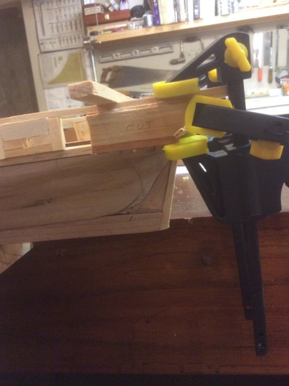
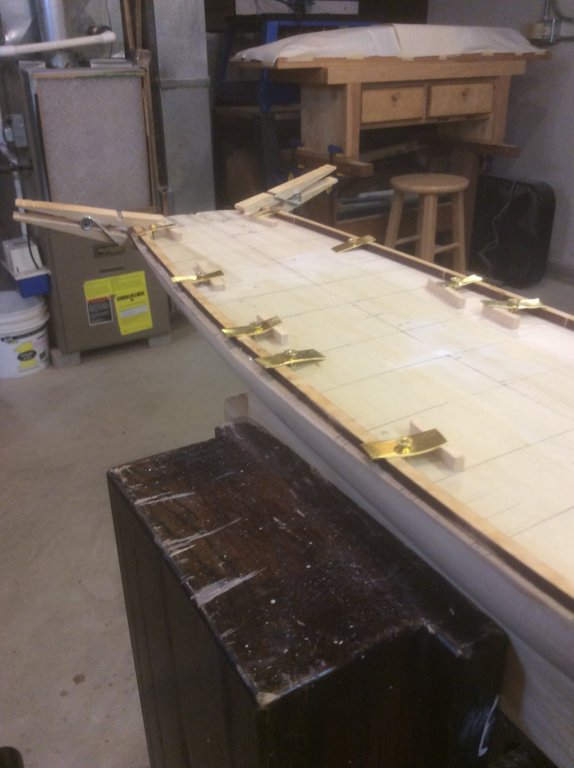
Can we trouble you to post a full pic of that cam- lock device?
- 3,618 replies
-
- 3
-

-
- young america
- clipper
- (and 1 more)
-
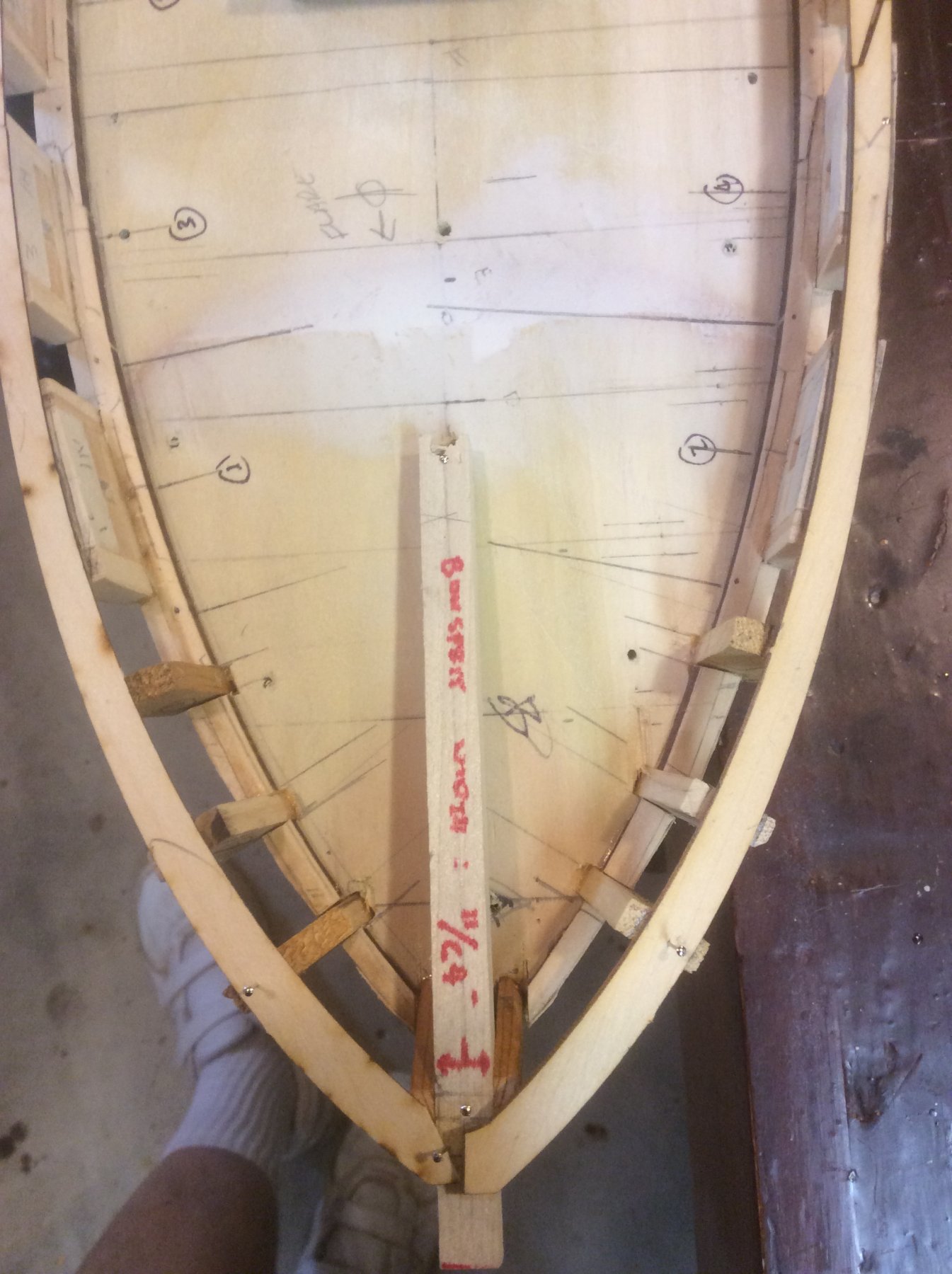
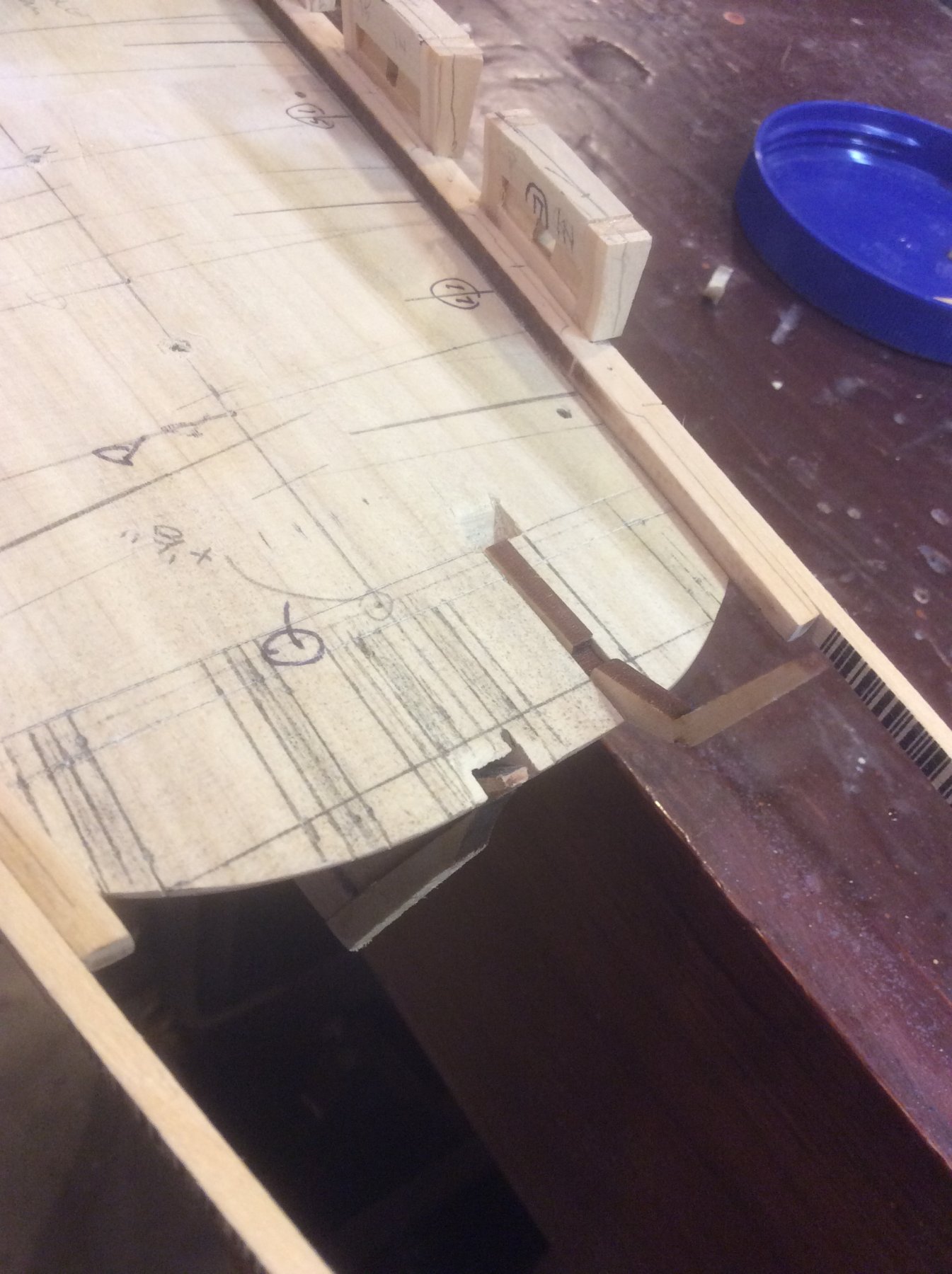
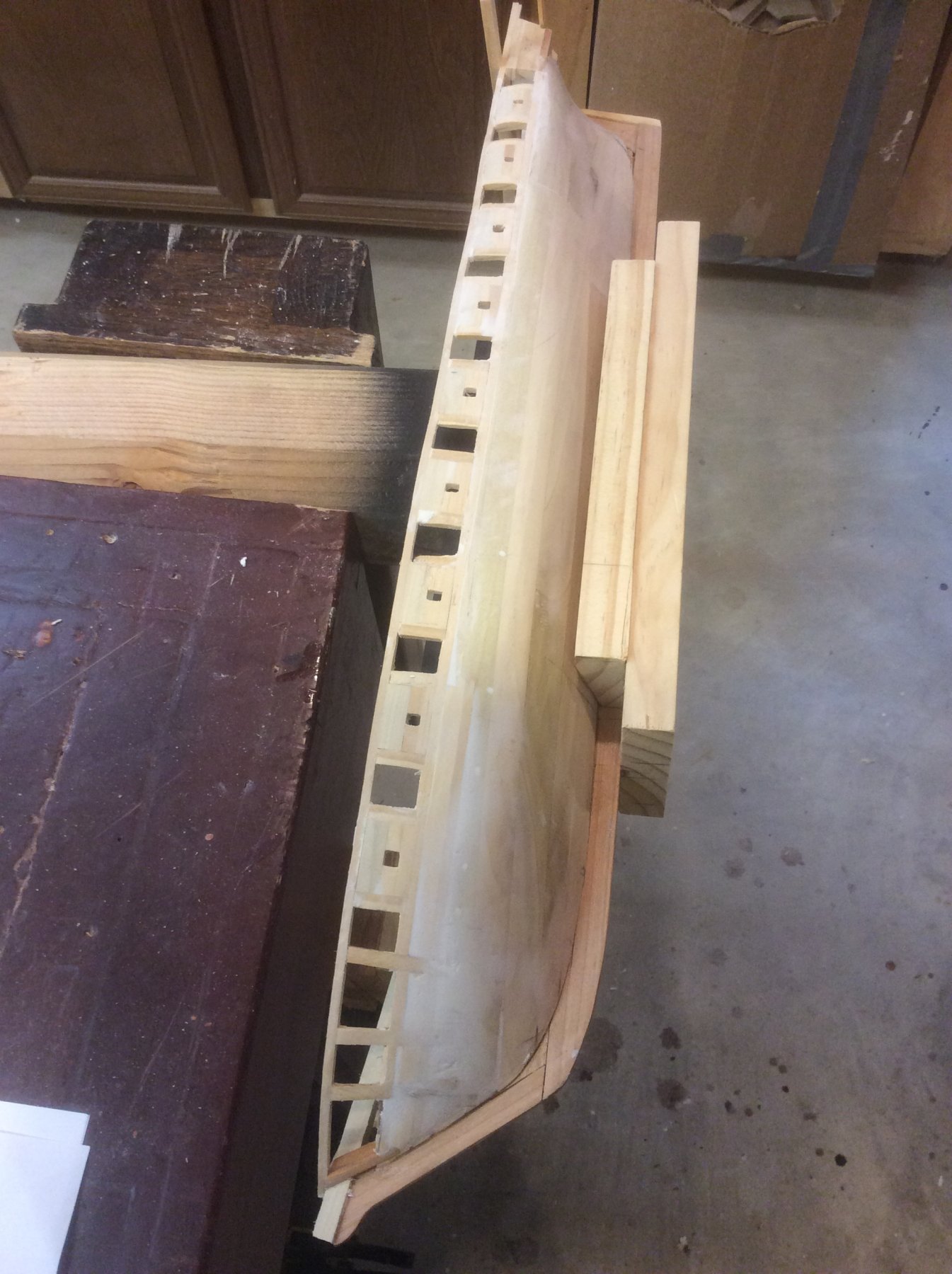
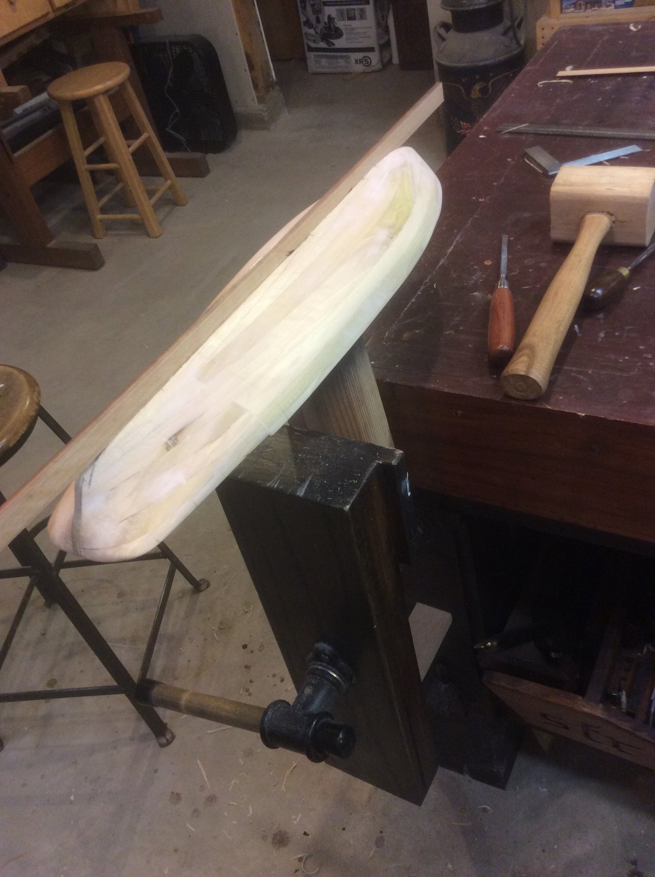
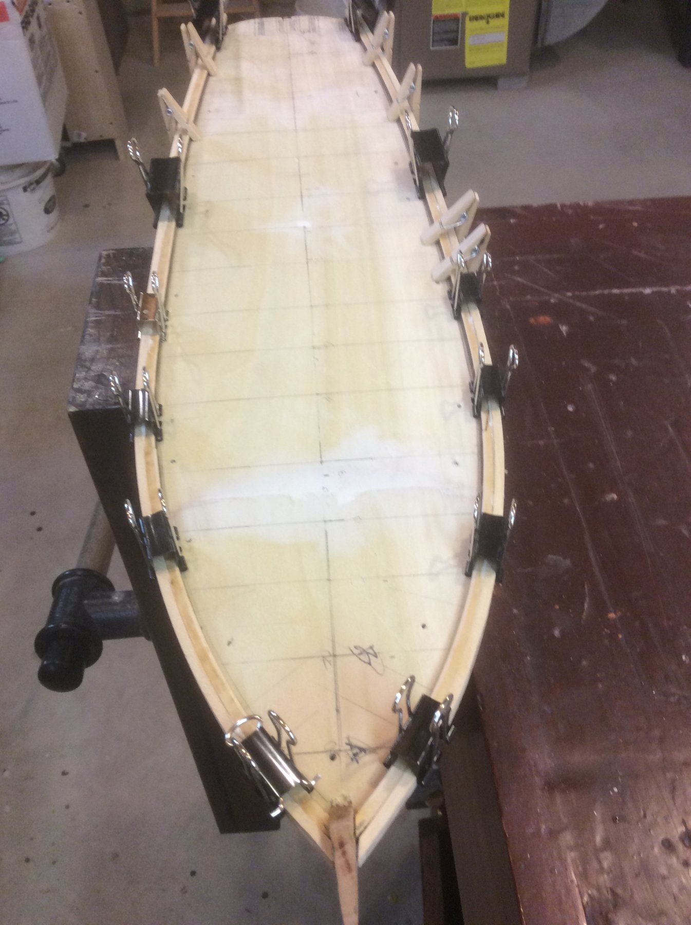
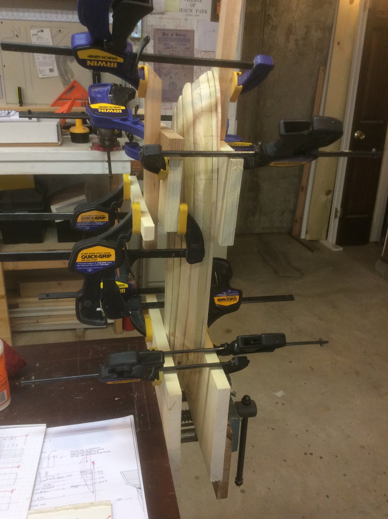
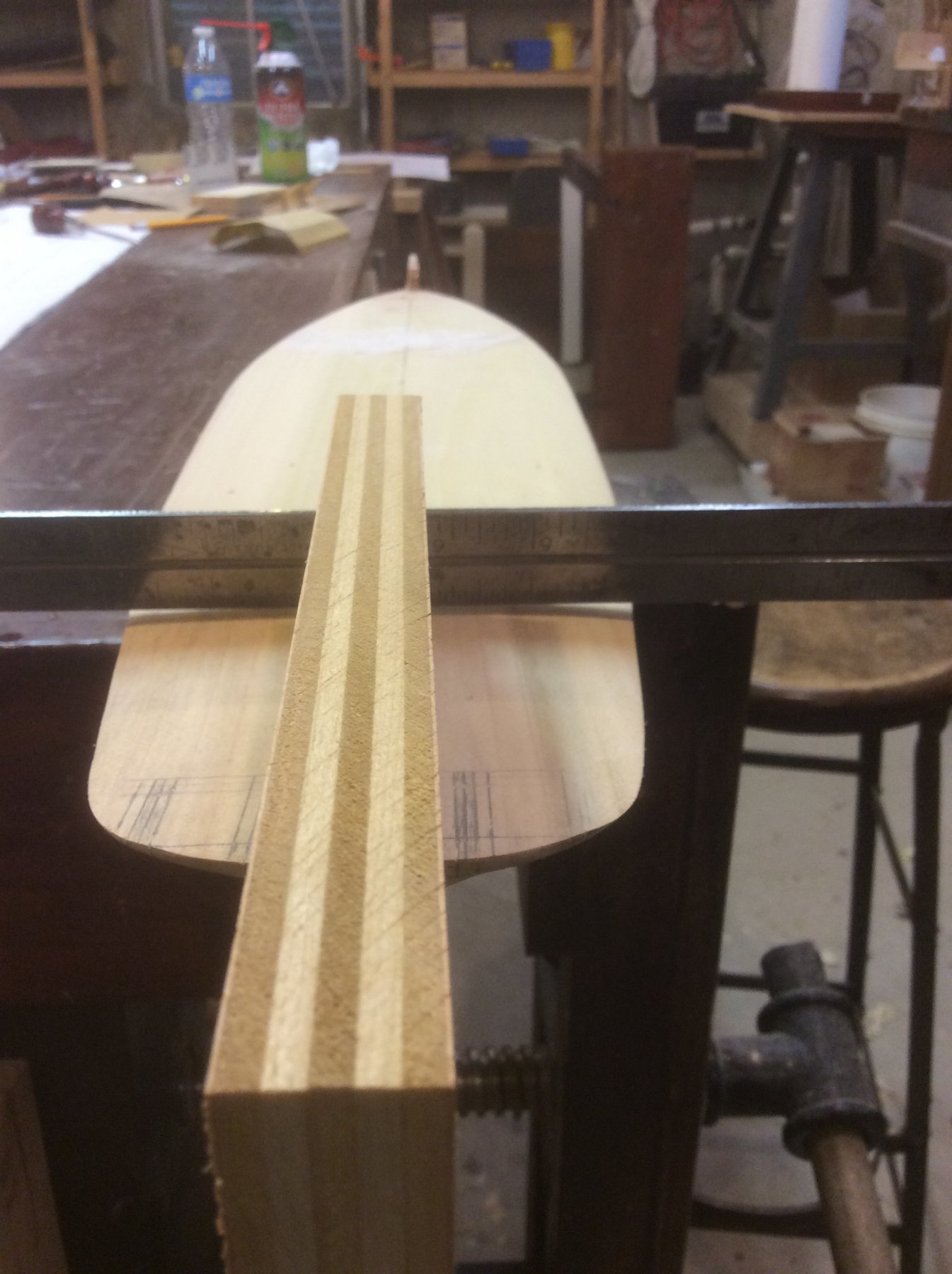
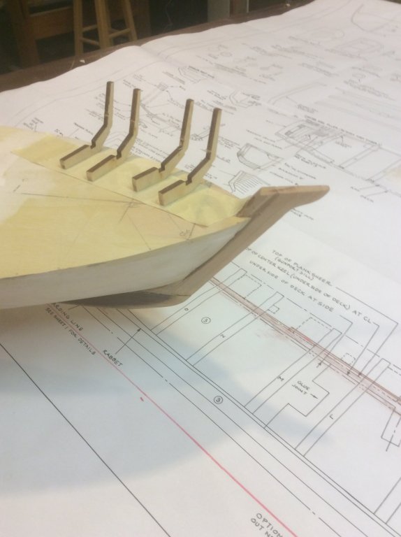
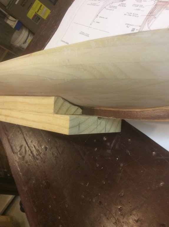
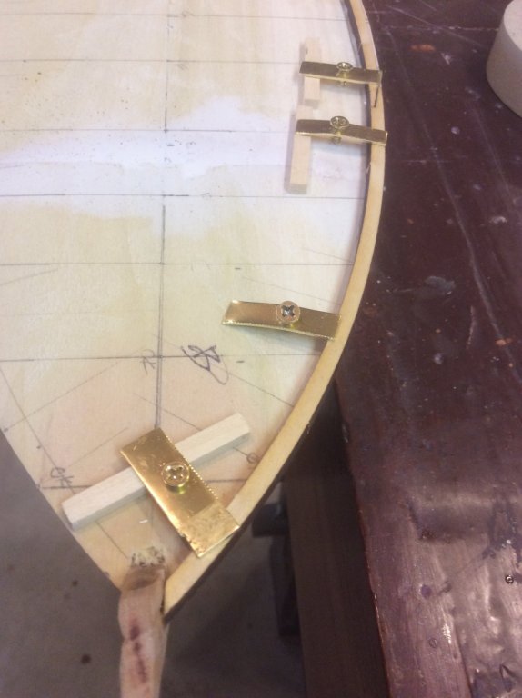
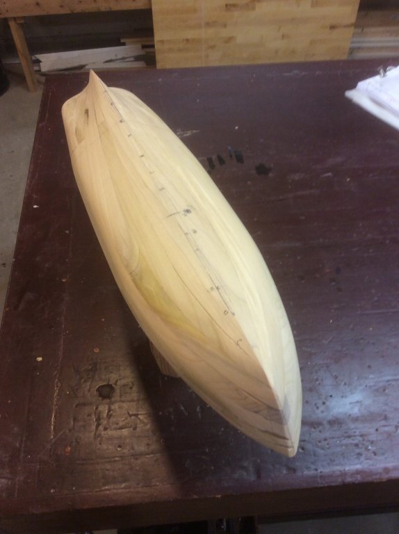
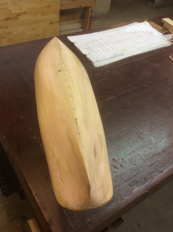
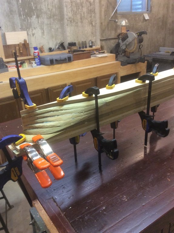
I have had the worst luck with keels on my builds. One came off, due to insufficient glue area, I think, and another split twice during the build. I was determined that the keel on this build was going to be more robust. I cut then chiseled a 1/4" groove down the centerline of the hull and inserted a piece of cherry that I had leftover from a cabinet project. I used the same material for the stem and stern, a secured with glue, clamps, and a few trenails for good measure. Ill do further shaping and sanding down to a more scaled width before planking, but for now these element remain capable of great abuse. After adding the keel, I added a strong mount to the bottom of the hull so I can hold the model in a vice while working topside. Going topside now to address the development of the bulwarks. When I fashioned the hull, I excluded the timberframes above the deck, and shaped the hull out to the sheer line. Looking at the drawing detail, the outboard edge of the waterway abuts the inboard edge of the laser cut bulkhead timberheads. So, if all turned out according to plan, when I used dividers to measure the plan distance from ship centerline to the waterway and transfer the location to the hull, I should have a bit of hull showing outboard of the outer edge of the waterway. Hey! Not too bad Oh-oh. Looks like I'll have to do some fixing at the bow. I soaked a couple of waterway extension strips and glued to the waterway to provide the base from which to build up my bulwarks. This put the sheer line beyond the hull at the bow as seen from below, so I'll have to return to this problem later. Over-zealous working with that bench plane, I guess (I just love those curly shavings flying when I get a rhythm going).


-
Pete: Thanks for referring me to your Eagle build log. Our solid hull methodology is similar, (though your workmanship far exceeds mine) but you will see in subsequent posts how I differed in my approach to the bulwarks. More than one way to skin that cat.
-
Oh, yeah. In my previous post that gunboat pic might be copyrighted by AP so if an administrator wants to pull it that's fine. My point is that the true appearance of Niagara may be more like the camels in Pathagoras's model than the Brig. (Love that display, by the way).
-
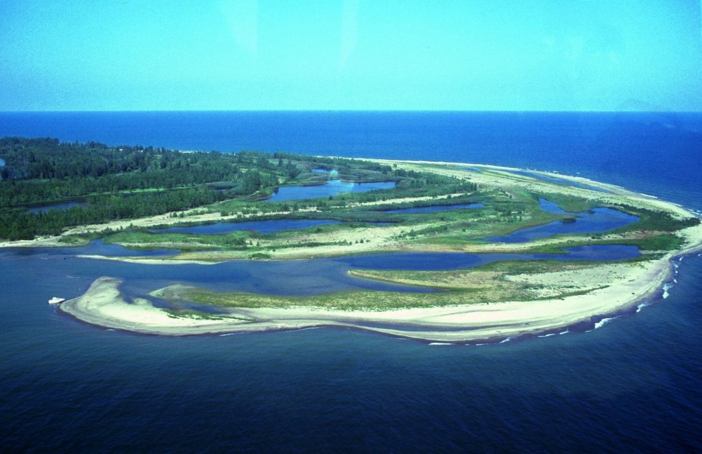
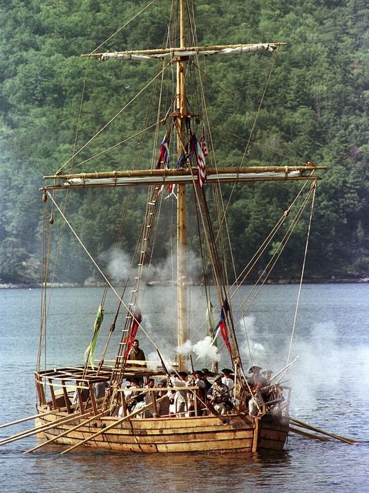
Pythagoras's model of lifting the brigs over the bar might be better appreciated in the context of this pic of Gull Point at Presque Isle. Lots of sand to deal with around there! Now that I've started my build of Niagara and am reading a bit more about the construction of the brigs, the picture is becoming much more clear that the originals were much more "rustic" (as someone said above). Given the time constraints, lack of materials and building talent, I wonder if they were just barely afloat? Given all the constraints, I can't help believing that "shortcuts" were taken. How many trenails had to substitute for iron spikes, and how many of those were installed spaced farther apart? Was there a lot of time spent faring the hull? How much did they plane the planking to get smooth surfaces? Was there enough oakum to fully caulk...were they really wet boats? Since Lawrence was started before Niagara, did she get any preference in use of available materials? Were they short of cordage, so the rigging they might not be as weatherly as desired? If so, could that have affected Niagara's sailing abilities (and contribute to Elliot's tardy arrival to the battle)? As far as the outward appearance, I'll bet they weren't too different looking than the gunboat (also built in a hurry) in the pic below. It would be interesting to build a model version of Niagara and Lawrence (as well as HMS Detroit) that focused on how deficient they may have been (compared to the "idealized" reconstructions we are familiar with). Which, IMHO, would only increase the appreciation of the battle.
-
Model Shipways Bluenose, Sails or not
Srodbro replied to Worldway's topic in Masting, rigging and sails
I also felt that sails on a schooner model were important. I also agree that if you have sails, you need water. Here is my We're Here. (Please forgive the temporary tape on the display case). I found that it was essential to reduce the sail area to about 60% of actual or the volume of sail material overwhelms the model, if sails are furled. Also, I find I get better looking sails when made of tissue paper than any cloth I've found. By saturating the bolt ropes in dilute white glue and allowing to dry before furling, the sail can be draped easily.
-
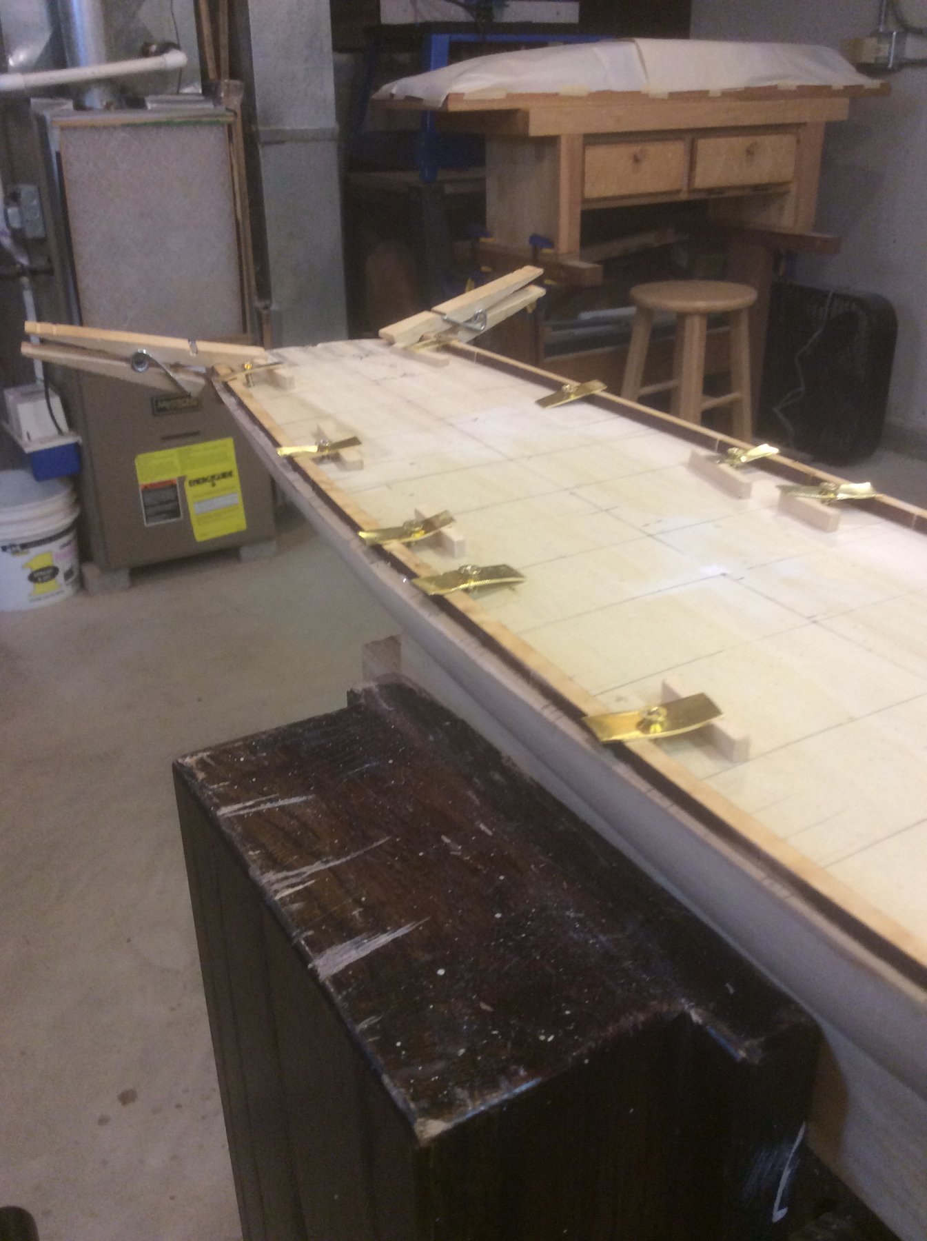
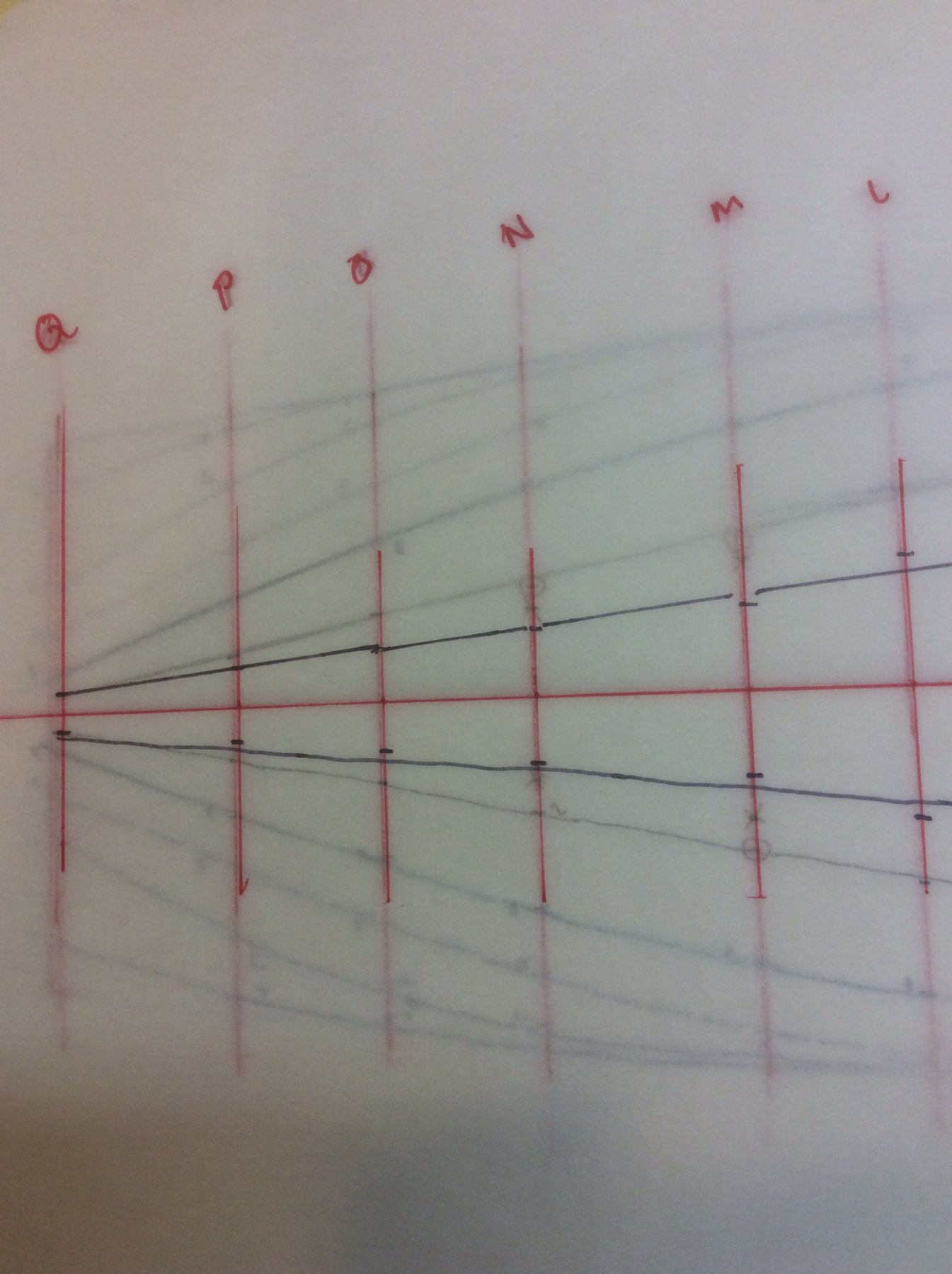
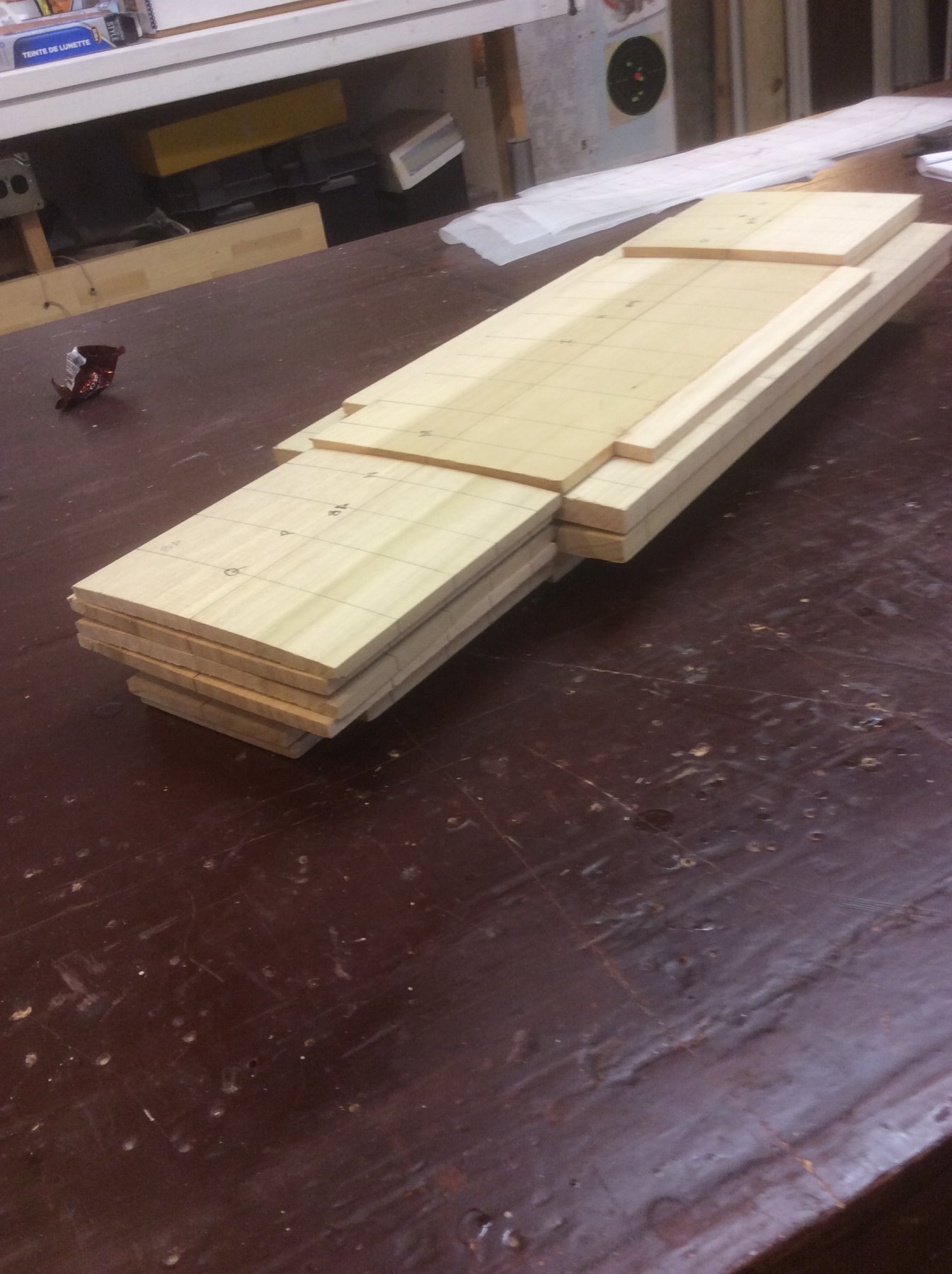
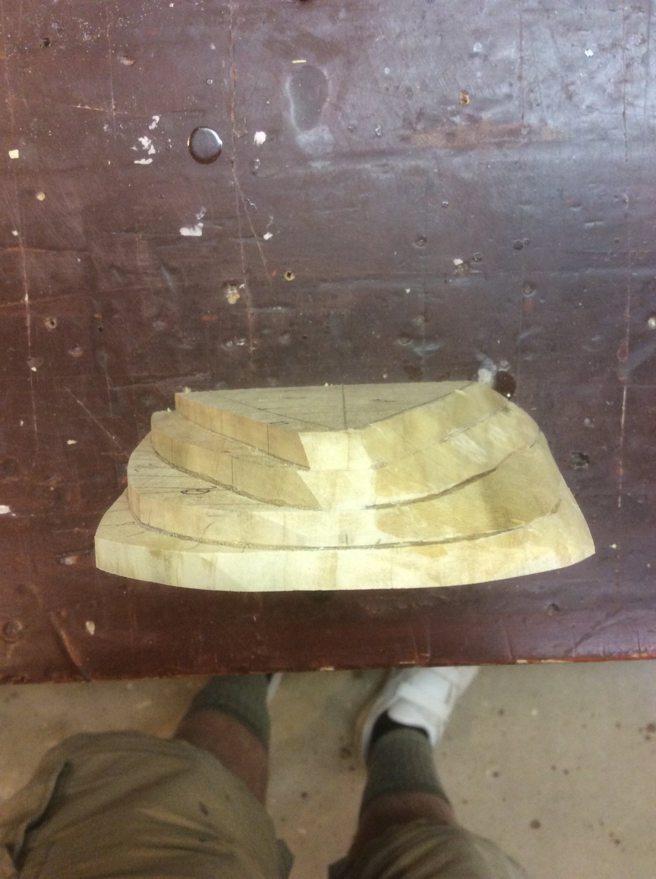
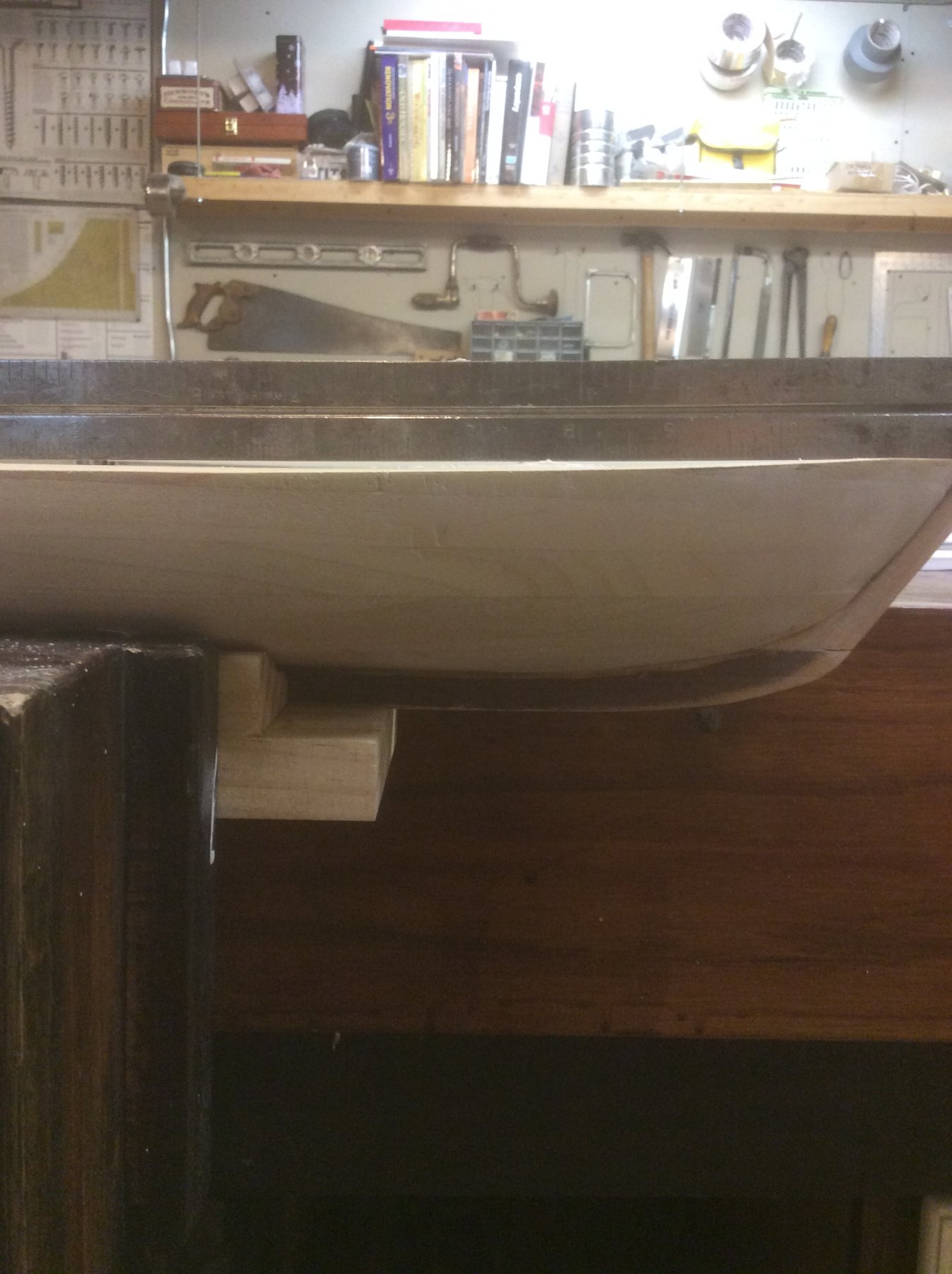
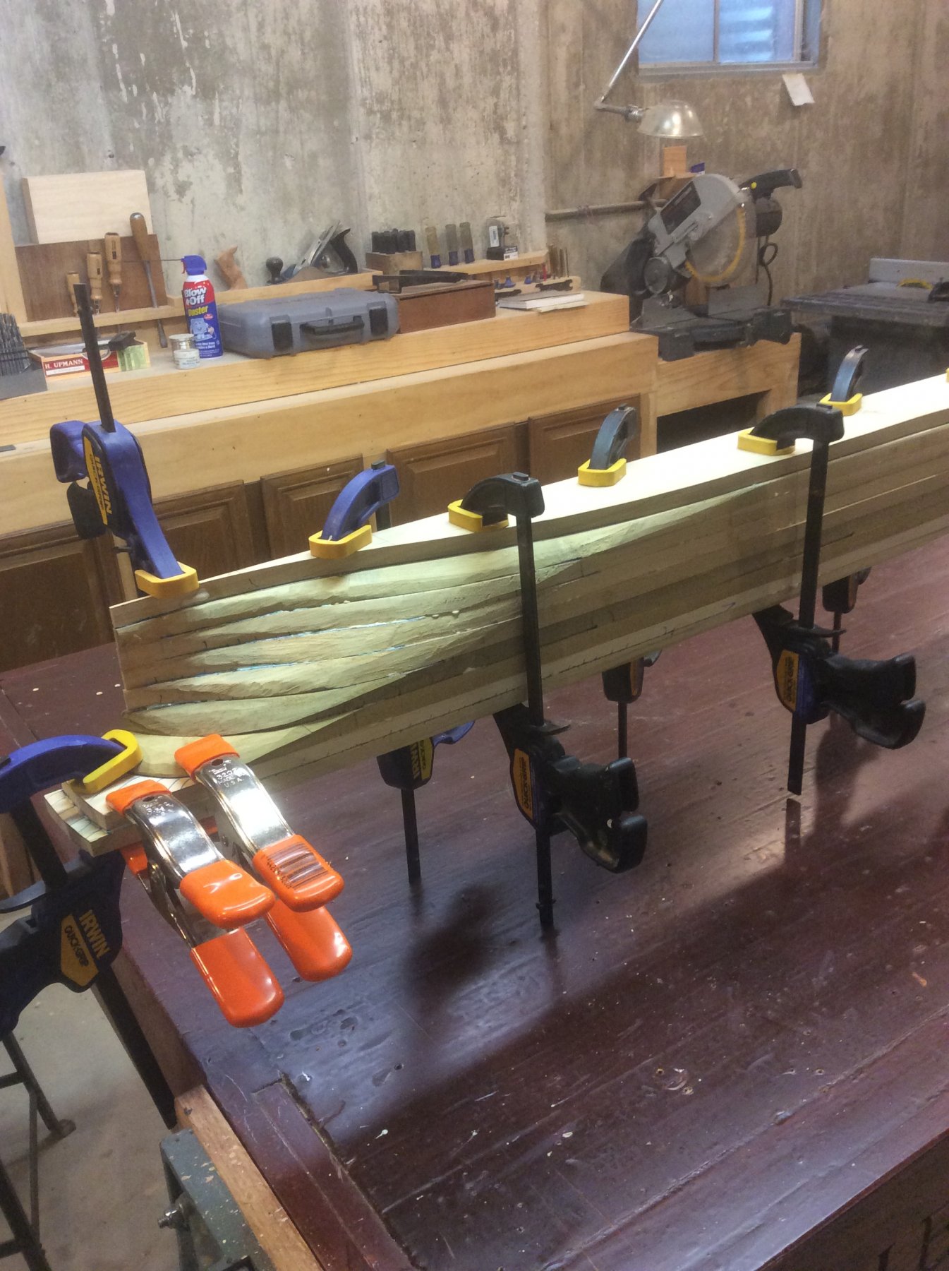
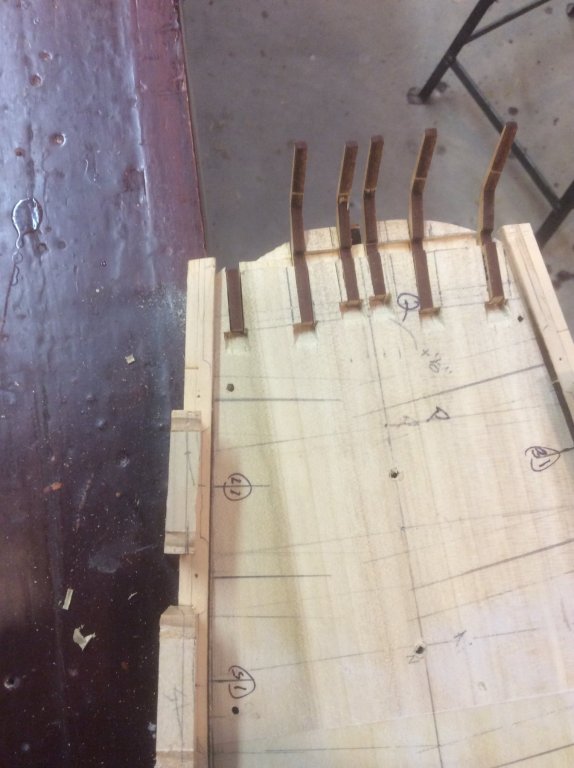
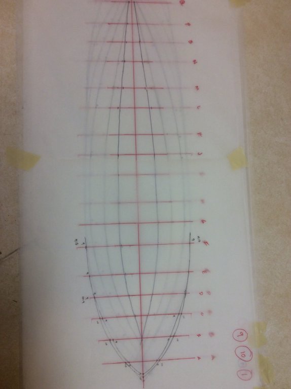
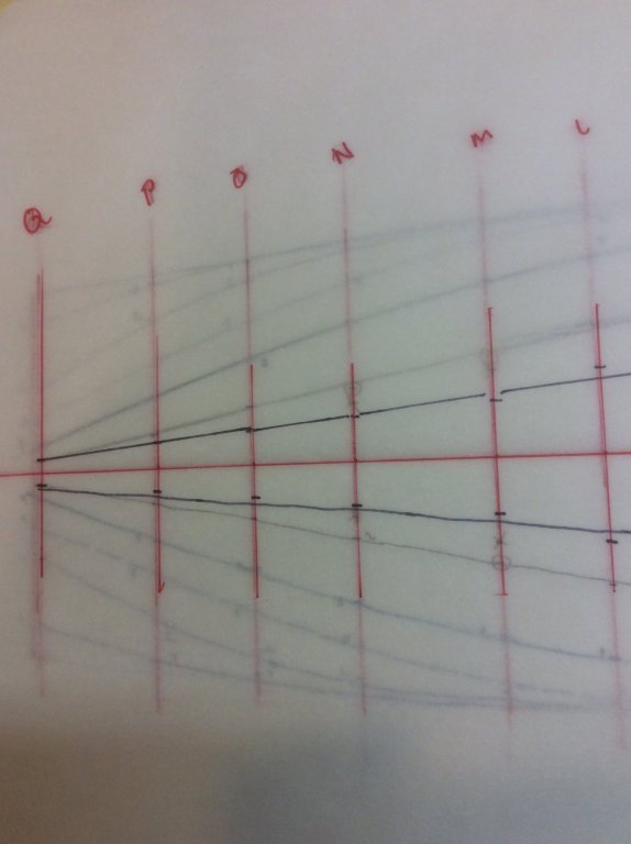
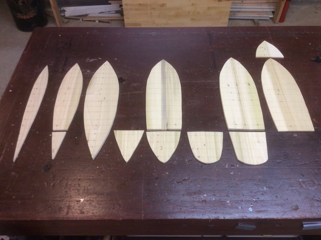
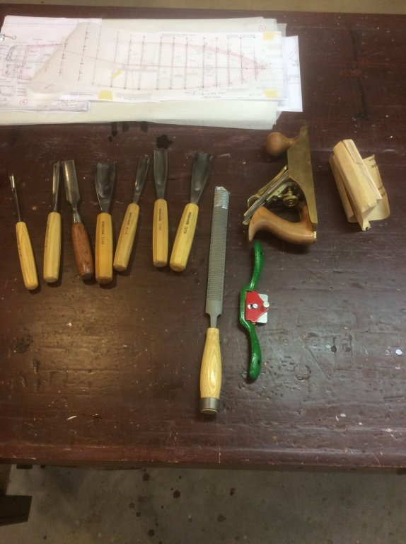
Here is a pic of the combined lift lines that I created from the kit drawings. I neglected to include anything aft of "Q" section line. (The pic is foggy in some areas because you are looking through nine layers of tracing paper. These sheets of paper I glued onto my lift blanks. i "corrected" this omission after having glued the patterns to the lift blanks, by taking points off the drawing detail 2-H, after adjusting for my lift blank thickness. But, I didn't really have a clear picture of how the complex shape of the hull married together with the sharp angles of the stern stanchions. In retrospect, I probably should have ended my hull at "Q" section line, but I didn't, I just smoothed the curves of the upper lifts to a pleasing termination. (Call this Big Mistake #1 -- BM#1 -- I'll revisit this later). Next I assembled the raw materials of my lift blanks into the proper size. I used poplar from the craft section of a local lumberyard, which came wrapped in plastic. The blanks were 1/4 and 1/2 (actually 7/16) inches thick. It didn't take long for these thin sheets to warp once in the humid basement shop. But, I figured (hoped) that by alternating the cupped surfaces the glue would bond them together. There is a split between section lines "M" and "N" which divides the aft third of lift 5,6,7 and 8, which are all 1/4" thick, from the forward two-thirds, which are 1/2" thick for lift 5/6, and 1/4" for lifts 7 and 8. This was done to provide more waterline lift points where the stern shape transitions so much more than the bow. The lifts below lift 5 are the full length of the hull. (I hope this doesn't wind up being BM#2!). After gluing on the lift patterns to each blank, they were cut out with a saber saw. The lowest three lifts were glued together, the aft-third four lifts glued together, and the forward lifts glued together, in three separate subassemblies to facilitate initial shaping. Here is the stern subassembly with initial shaping on the right Then the three subassemblies were glued together. After setting up in the clamps and vice overnight, I gathered together my arsenal for shaping the hull. I used the Waste" from around the kit's laser cut bulkheads as templates for the shaping. Rasping, sanding, filling, more sanding, and an acceptable hull emerged. Then the topside needed attention. There is a slight rise to the deck from stern to bow. And a camber to the deck from centerline to the sheer. This pretty much completed the major shaping of the hull.


-
6ohiocav: A couple factors contributed to my choice of approach. Familiarity with working on solid hulls; knowing that a solid hull can take a lot of abuse during the process; ease of securely mounting it while working on it. I also saw that most builders add varying amounts of blocking between bulkheads to reinforce the skeleton (not the least of which was illustrated by your log, of fillers between A and B bulkheads as well as everything aft of "O" bulkhead. I figured there wouldn't be too much more involved to just make it solid to begin with (which I am learning may not be entirely true) -- but, that's the heart of the experiment. The closest the laser cut bulkheads are coming to being used in the model is that I'll be using the "waste" that surrounds them as templates to check my hull. As following posts will show, I am constructing the hull of laminations as might be done for a half-hull model.
-
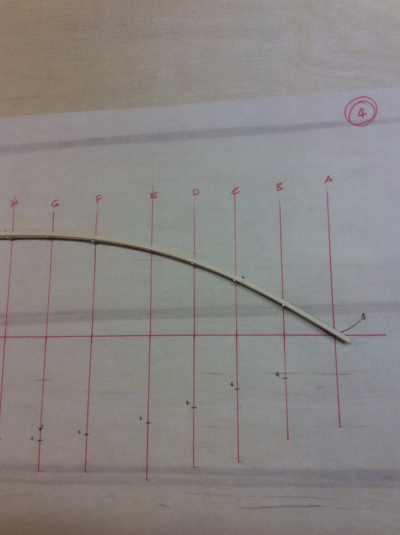
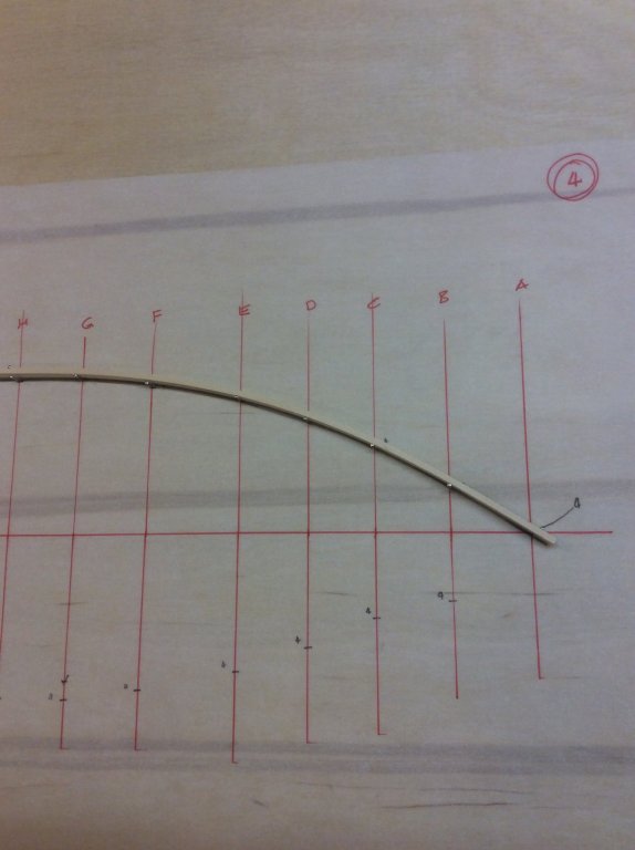
This will be my first build log, and I wasn't sure if I should have it here, in the Kits forums, or in the Scratch build forums, since I am diverging so much from the normal, plank-on-bulkhead technique. I decided on the Kit forum, since nearly everything I'm doing is, well, based on the Model Shipways kit and drawings. All of my previous builds (Yankee Hero, Fannie Gorham, We're Here, Dapper Tom, and a recent 1/2-hull - 1/2- model of six masted schooner Wyoming) have been solid hull projects. I found dealing with my builds of New Bedford Whaleboat (PoF) and Grand Banks Dory (PoB) to be tedious due to the light weight construction. When I decided to build Niagara, I thought I'd try to construct a solid hull upon which to later apply the planking, and then complete the model per kit instructions. I have made some some progress on this effort, and thought I'd share the experiences of this experiment. A couple of thoughts to begin. My old microbiology professor preached "Hinkley's Law", which said "Most experiments are failures." I expect that may turn out to be true for this one, as well. During this build I have found the build logs of 6ohiocav and mikiek very informative; the website Niagaramodel.com is invaluable. The responses to my earlier post on planking a solid hull by BACKER and Pete Jaquith were helpful. I chose to ignor the advice in wefalck's response (sorry). So, here we go. Hold fast! My first task was to create a set of waterline drawings from the drawings in the kit. Let me say up front that creating these was fraught with the opportunity for error. Every time a point is transferred from one drawing to another, or from paper to wood, error can occur. I calculated that given the number of sections, the number of points on each section, the number of transfers, I had a 1 in 960 chance of matching the kit drawings. At best. I first drew onto the kit sections of the bulkheads the outline of my wood layers. From these I measured from centerline to the intersection of each layer with the section curve of the bulkhead. This distance I transferred to an overlay of the kit plan. Then, on another overlay, I connected the points for each layer by faring with a wood strip pinned to the drawing. This gave me a pattern to glue to my wood layers for cutout. Next: attacking the wood.


-
Thank you.
-
Following your build log with great interest. I, as well, am building Niagara. But, in reviewing several build logs, became concerned with the lengths to which builders have to go to keep everything square and rigid, so decided to build a solid hull based on the kit drawings and templates. I had to construct my own waterline plans since the kit plans didn't include them. I fared the points taken from the kit section drawings and plotted onto a plan using pins at each point and a strip of wood. I found several points, on section line "M" and "N", about midway between the keel and deck, where the hull shape transitions from convex to concave, that could not possibly be "fare". I noticed that your pic shows shimming at section "F". I was wondering if you tested the "M" and "N" area with a batten , and if so, have you found the need to shim at this location.
- 18 replies
-
- 1
-
-
- niagara
- model shipways
- (and 1 more)
-
Planking a solid hull
Srodbro replied to Srodbro's topic in Building, Framing, Planking and plating a ships hull and deck
Thanks to all for your tips. I have decided to go ahead and build-up a solid hull, having lifted water lines from the kit drawings. Should this approach fail, I still have all the kit components, to which I can add fillers from the failed solid hull (if that comes to pass), and then proceed per kit directions. Thanks again. -
I wound up using poplar obtained at a local woodcraft shop, primarily because it was readily available, dry, square, and the thickness (1/2") was same as the waterline spacing on the drawings. It works quite well with hand tools. I think it turned out OK. I think because of the many layers in the glue-up it will be pretty stable. When I mounted it on the oak backboard, I secured with wood screws, but used slotted holes to allow for any differential expansion between the model and backboard.

-
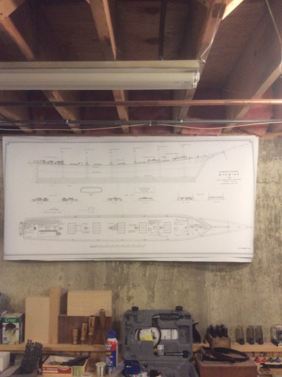
Stapled to the sill plate above the concrete basement wall, or for small plans, buried under the project materials on the bench.
-
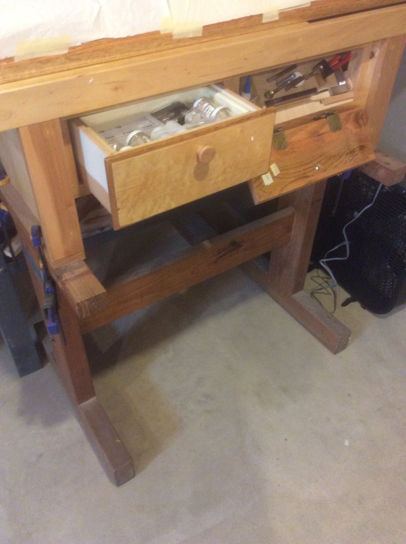
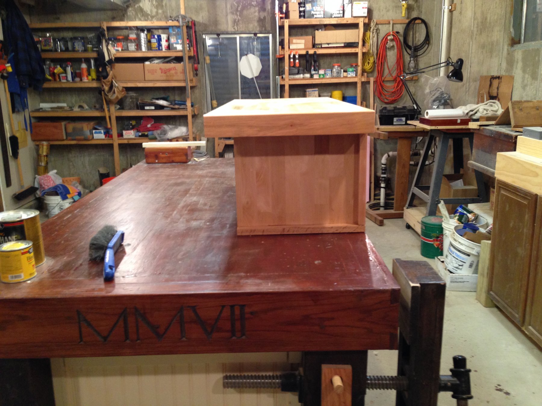
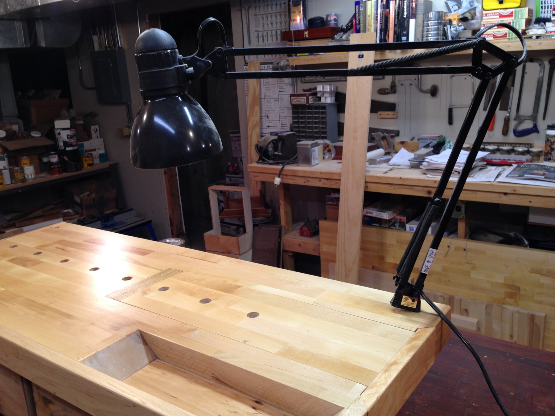
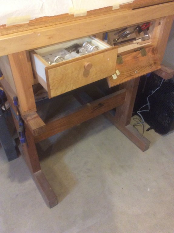
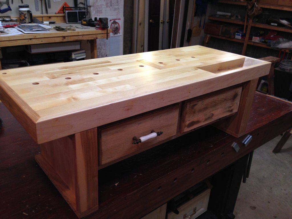
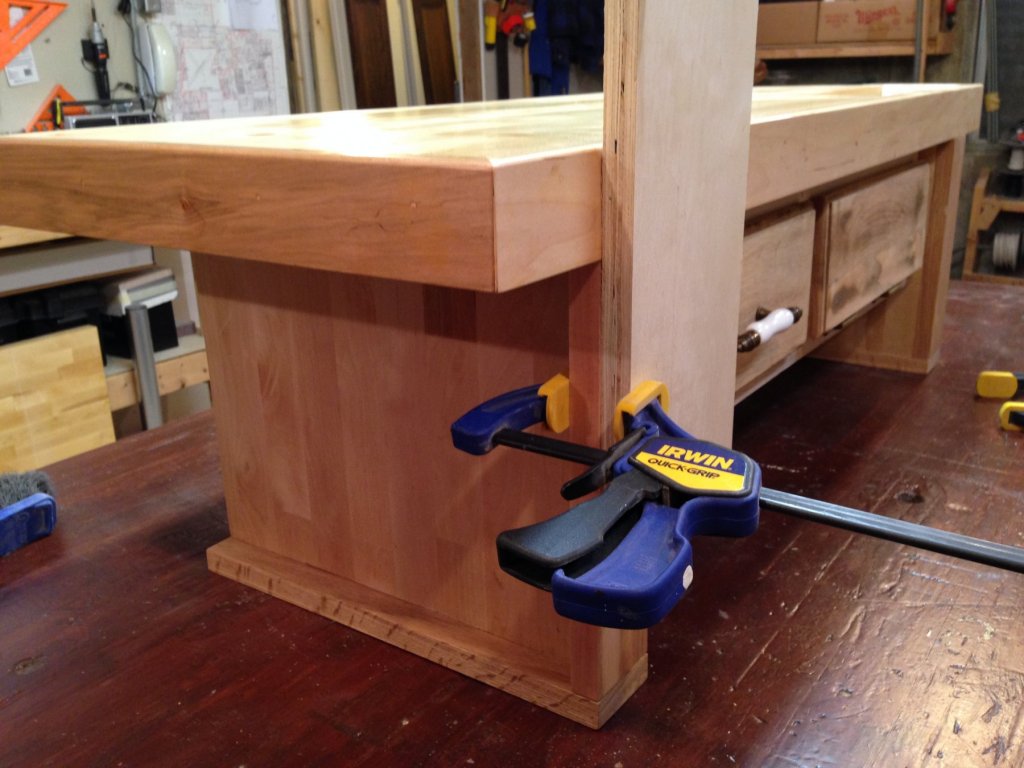
Just a basement workshop, but I did construct a mini-bench for my models. Modified from some drawings in a woodworking magazine, I have a center "tail vice" that can hold inverted hulls in about any position or used with bench dogs to hold things mounted on flat base, a depression in the top for tools/parts, drawers for frequently used tools and parts, and a mounting hole for the all important light. But, the best feature is its portability. When not mounted on the main shop bench, it can be mounted with clamps on a pair of sawhorses, or moved to a table elsewhere. I like working standing up, and the height is just right for that, and the mini-bench facilitates resting your arms on it while doing fine work. If I decide to work seated, I move it to the sawhorses. The legs are designed with flanges to allow clamping work to them as well. Finally, when the Admiral demands work on another project, the bench with model can be moved out of harms way.


- 43 replies
-
- 14
-
-
Planking a solid hull
Srodbro replied to Srodbro's topic in Building, Framing, Planking and plating a ships hull and deck
Thanks so much for your response and directing me to your build log. Great project -- beautiful workmanship. I look forward to following your progress. While you have filled between bulkheads (frames), I intend to eliminate bulkheads altogether by making a solid hull. I noticed that you have used wood filler in some locations, which I anticipate I will need to do as well. I am curious as to whether you applied adhesive to any of your filler to attach the planking, and if you have any concerns about the compatibility of the filler and adhesive? -
My next build will be the MSW Niagara. This is my first PoB kit. All previous builds have been solid hull, including my most recent, a 1:96 scratch-build half-hull of the six masted schooner Wyoming. While reading several of the build logs for Niagara and Syren, I've become concerned with all the effort required with keeping bulkheads square and properly aligned (construction of special jigs, etc.) proper beveling of the edges, removing laser charring, and then learning that, in addition to having to carve the bow and counter, many builders find they need to add solid fillers between the bulkheads to keep things rigid. So, I am considering just building a solid hull to begin with, then planking it. In searching the forums and the Sultana practicum, it is clear that planking solid hulls is not unusual (and frequently done in Europe). Seems straightforward: Just follow the same planking methodology as PoB or PoF, knowing there are a lot more points at which one could apply glue and insert temporary pins. As a bonus, the "waste" around the laser-cut bulkheads in the kit will provide nice templates for shaping the hull. Aside from the need to develop my own lift lines from the kit sections, and forever dealing with a heavier hull, I can't think of any major obstacles. My question is: Does anyone know of any special considerations for planking a solid hull?