Srodbro
-
Posts
299 -
Joined
-
Last visited
Content Type
Profiles
Forums
Gallery
Events
Everything posted by Srodbro
-
Thank you, Pat. To all : I have posted at his question on EdT’s Young America build log and he responded. I anticipate others might respond there.
-
Rigging Question - Virginia Privateer
Srodbro replied to David Lester's topic in Masting, rigging and sails
No, no ! ... please don’t leave it off. I’ve fallen in love with the Dapper Tom, Baltimore Clipper (fictitious), have completed one, but have two more in progress. My first has square topsails on the main mast, but I intended to have the gaff topsail on the next one. I, too, posted an inquiry about the rigging of this sail some time ago, with little success. Somebody called it a “Sliding Gunter” topsail, or something like that. It looks like you have a more responsive audience, and I’d love to see how you carry it to completion...so I can copy it. -
Allow me to second the comment about Syren rope. I’m not nearly in the same league of most modelers in these forums, but I will say I consider Syren rope as important to my modeling as my Dremel tool.
-
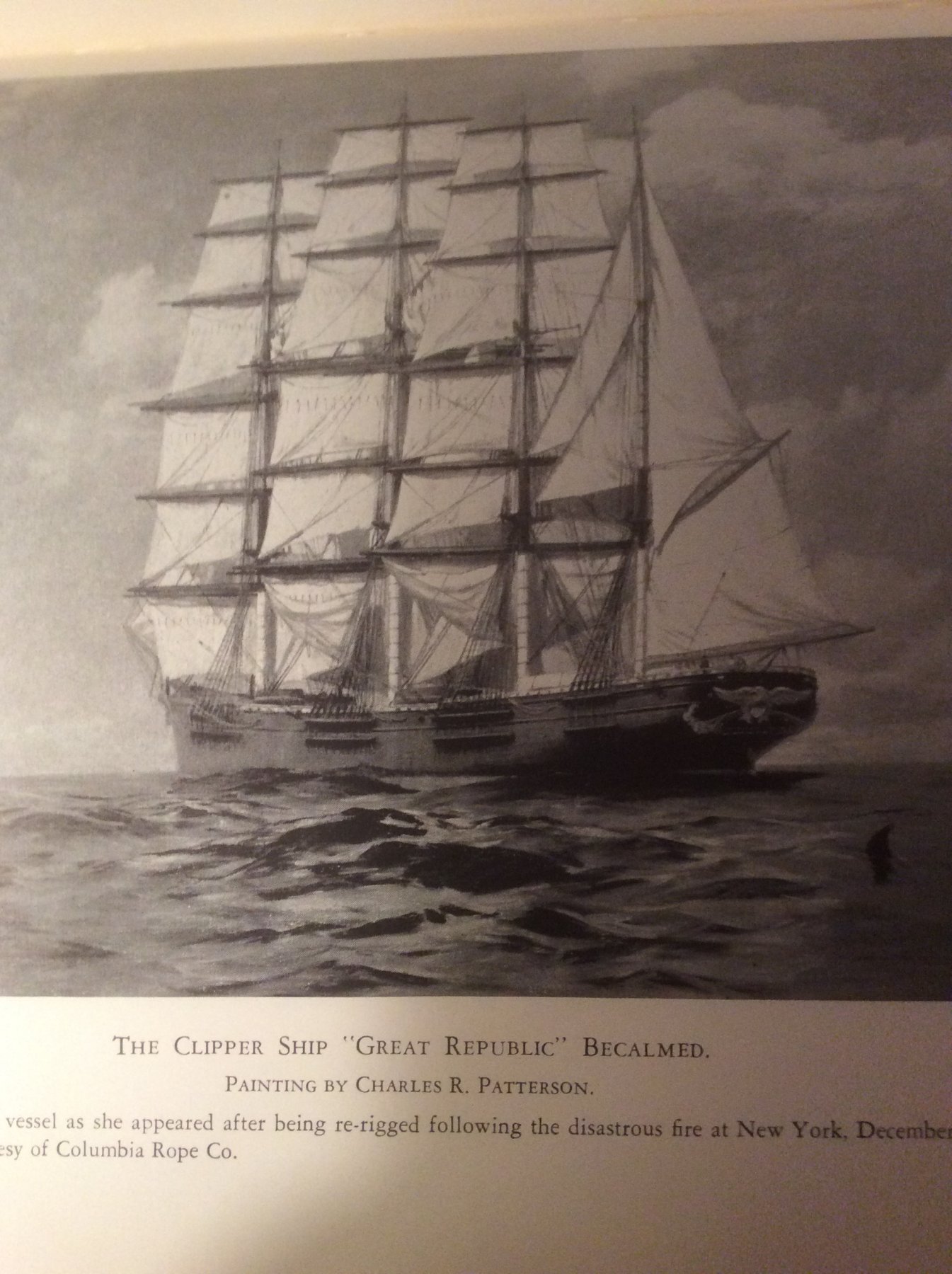
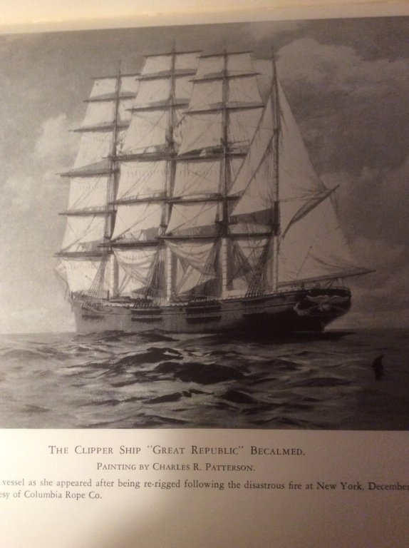
Ed: I posted this question in another topic and another member suggested I post the question directly to you in this build log. I recently noticed a detail in the pic above (from Greyhounds of the Sea by Cutler, of the Clipper Great Republic) showing double channels, one above the other, at each mast. I also found this arrangement on Queen of the West, in Chapelle’s History of American Sailing Ships, on a pic of a build of Thermopylae, and after digging through your Young America log (Part 158), there it was as well. My question is, Why double channels? I surmise that the lower channel facilities extending the chains to a lower point of attachment to the frames, perhaps at a more robust location, where forces from the shrouds might better be absorbed. But, that’s just a guess. I thought you or another “clipper” guy might be able to enlighten me. Thanks, and sorry for hijacking this topic.

- 3,618 replies
-
- 2
-

-
- young america
- clipper
- (and 1 more)
-
Ah ... good idea. Thank you. I shall.
-
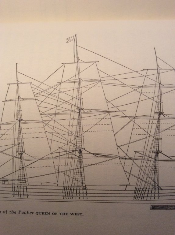
I have come across two examples of a detail I’ve not noticed before: double channels located one above the other, for each mast. I don’t understand what advantage they offer. The illustrations below are from Greyhounds of the Sea by Cutler (the Great Republic) and from History of American Sailing Ships ’by Chapelle (Queen of the West). I can only guess that this arrangement locates the point of attachment for the forces of the shrouds to a more robust location, lower on the frames. (Note: After my original post, I noticed this double channel detail is best illustrated in EdT’s Young America build log, Part 158). Still have the same question, though.
-
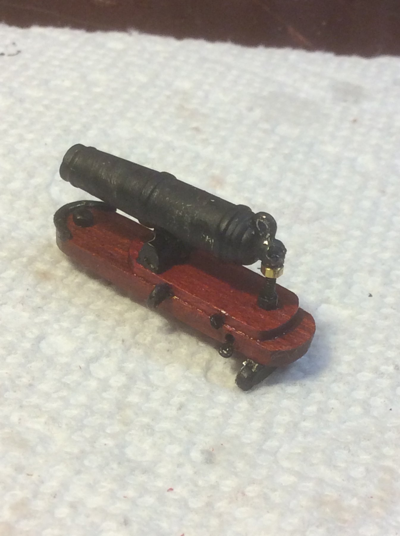
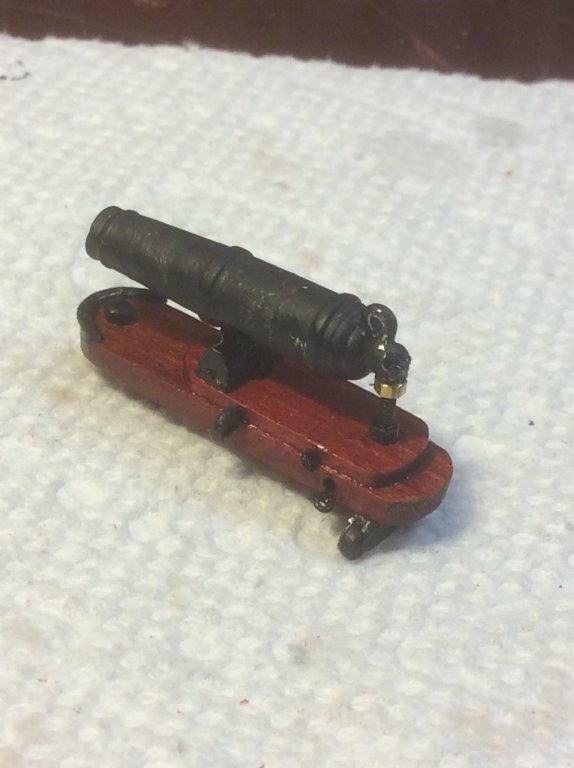
I was assembling carronades today, attaching eyebolts to the carriages, using CA. The eyebolts are blackened brass, the carriages are wood (Redheart with a touch of TruOil finish). I dabbed the joint with a small piece of paper towel to wick away the excess adhesive. I was wearing a pair of Optisight magnifying visors, and when I applied a very small amount of CA, I noticed smoke coming off the assembly. And when I touched the eyebolt with my finger to assure it was secure, it was hot! I have touched parts secured with CA that felt hot before, and thought it was my imagination, but seeing the smoke confirmed it. I have read that CA in contact with cotton or wool will spontaneously combust, but was not aware contact with wood (or was it the blacking agent, or the TruOil, or the brass, or the paper towel?) would cause such an exothermic reaction. Is my experience unique?
-
Jim:
I just today noticed your post in jablackwell’s Syren build log on 11/29/2017 and your use of Redheart for the ceiling on your build. I have been doing the same on my Lawrence (aka, Niagara with modifications).

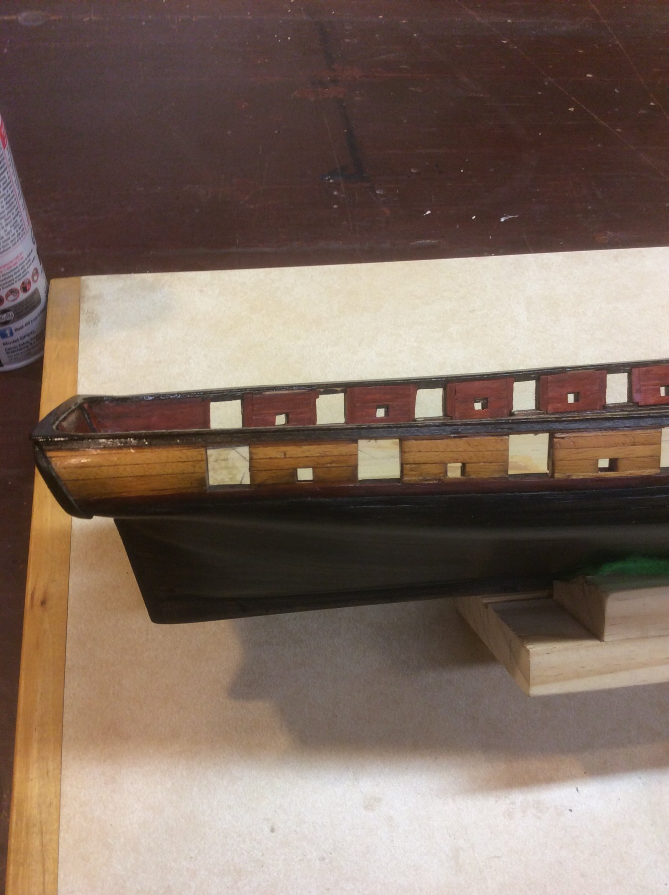
I used Redheart for the bulwarks ceiling, and Osage orange for bulwarks exterior planking.
So, a couple questions for you ...
I read that the Redheart will fade over time to dull grayish-red, so lightly coated with red stain. Did you do anything to preserve the color?
both of these woods were very hard and brittle. The first strake below the gunports on the exterior is Redheart and no matter how long I soaked it, the planks snapped when bending. I finally had to plane the plank down to nearly 1/32” to get it to bend. Did you have similar issues?
I am also using Redheart for carronade carriages.
Thanks.
-

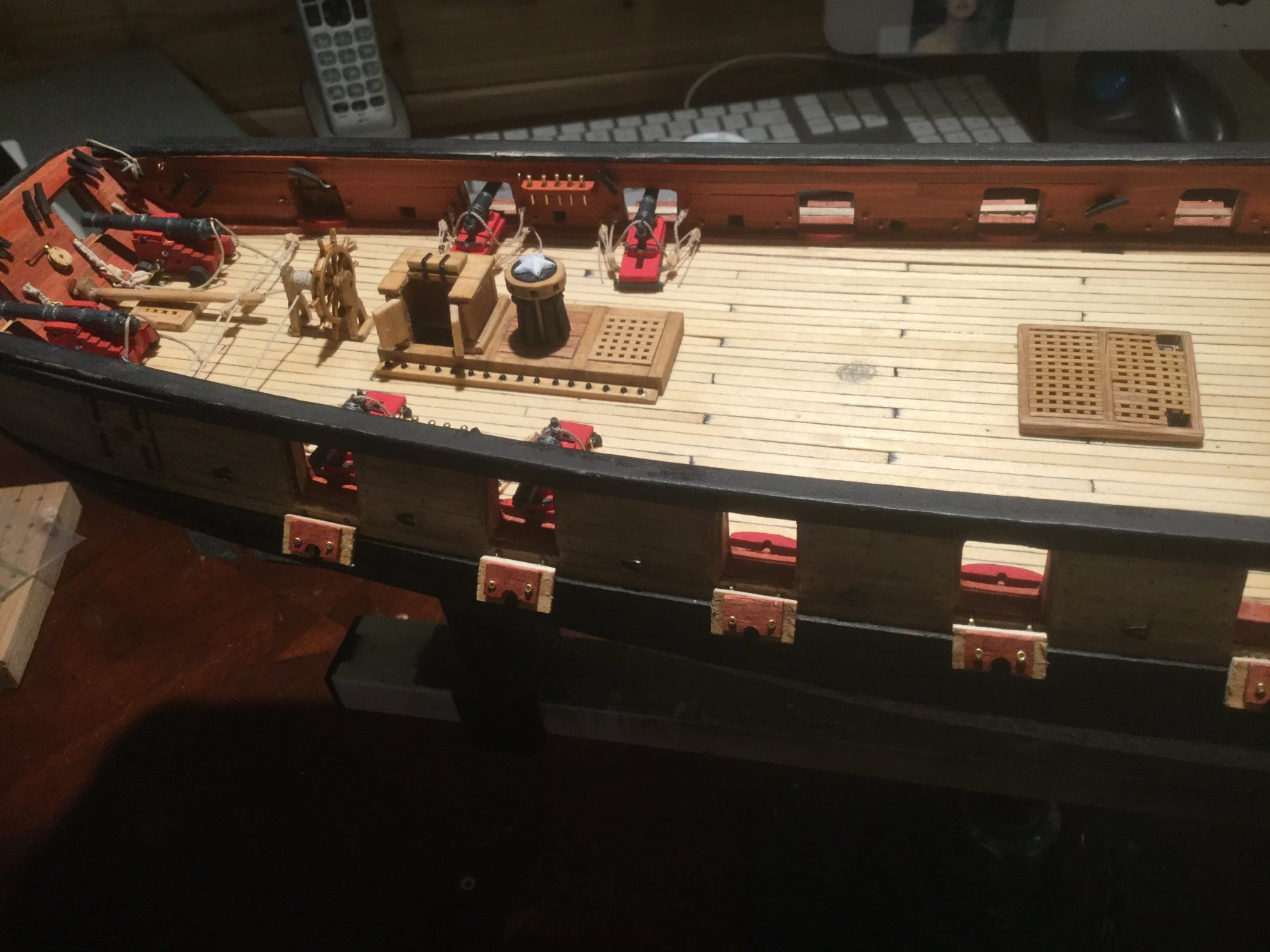
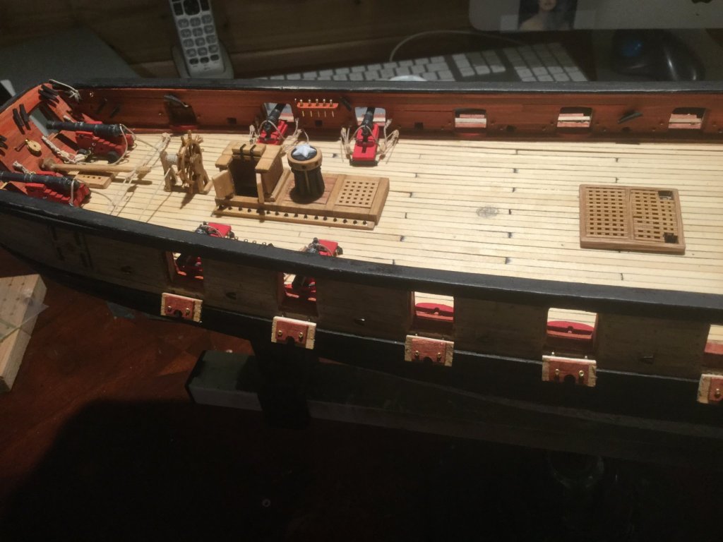
I steam bend with no issues. I tried the soaking routine and had the same results as you. I coated mine with a satin poly after installation. OMG what a color pop. You can also use Tung oil. I also used Redheart on my Rattlesnake ceiling and loved it. Another wood I use is Yellow Cedar for decks. A lot of people use Holly because they say it resembles a hollystoned deck but I think it is just to white. The cedar is the perfect shade. Not brown not white. I thought about doing the carriages with the Redheart but I like the contrast between the Redheart ceilin, Cedar Deck, black fittings and flat red carriages. That is a very good looking Carronade. Like the pop of brass.Your Lawrence is going to be stunning when complete. Here is a photo of where I am now. I build from stern forward and try to complete everything in a section prior to moving on.
-
Good looking build you have there. I almost like your flat red gun carriages slightly contrasting with the deep red Redheart more than my scheme (almost).
I like your light colored deck. Mine will be a bit more subdued, using mahogany with a light gray stain and satin poly finish. I intend to make the companion-way, grates, and fife rails of walnut. But, with this color scheme based on natural wood colors, I’m not yet sure what I’ll do with finishing the spars and tops.
-
-
-
I saw your pics in the gallery this morning at breakfast and have spent today going through your entire log. Wish I’d have looked in sooner. Picked up several tips along the way. Thanks. So glad you spent the time to chronicle you journey. Great work. Thanks for sharing it.
-
Ah, yes. Felt. I had forgotten. I did so on a previous build and it worked well (even though the mounting screws caught some of the felt material and drove it into the hull .. this time I’ll cut out felt at the screws). Thank you.
-
Thank you.
-
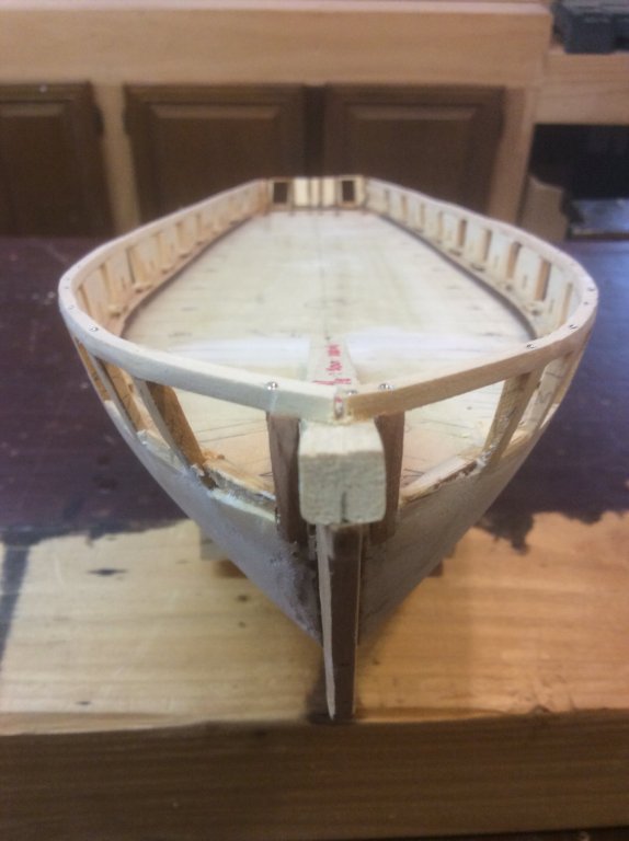
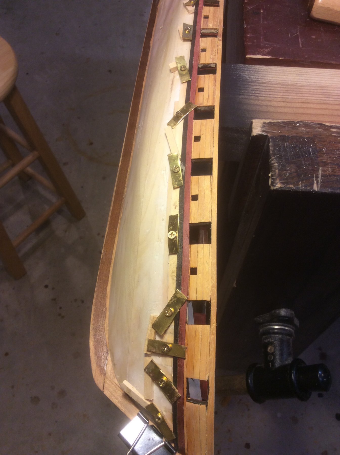
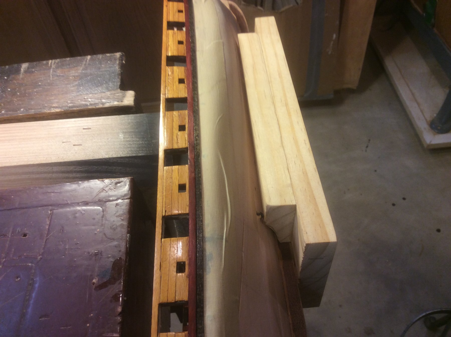
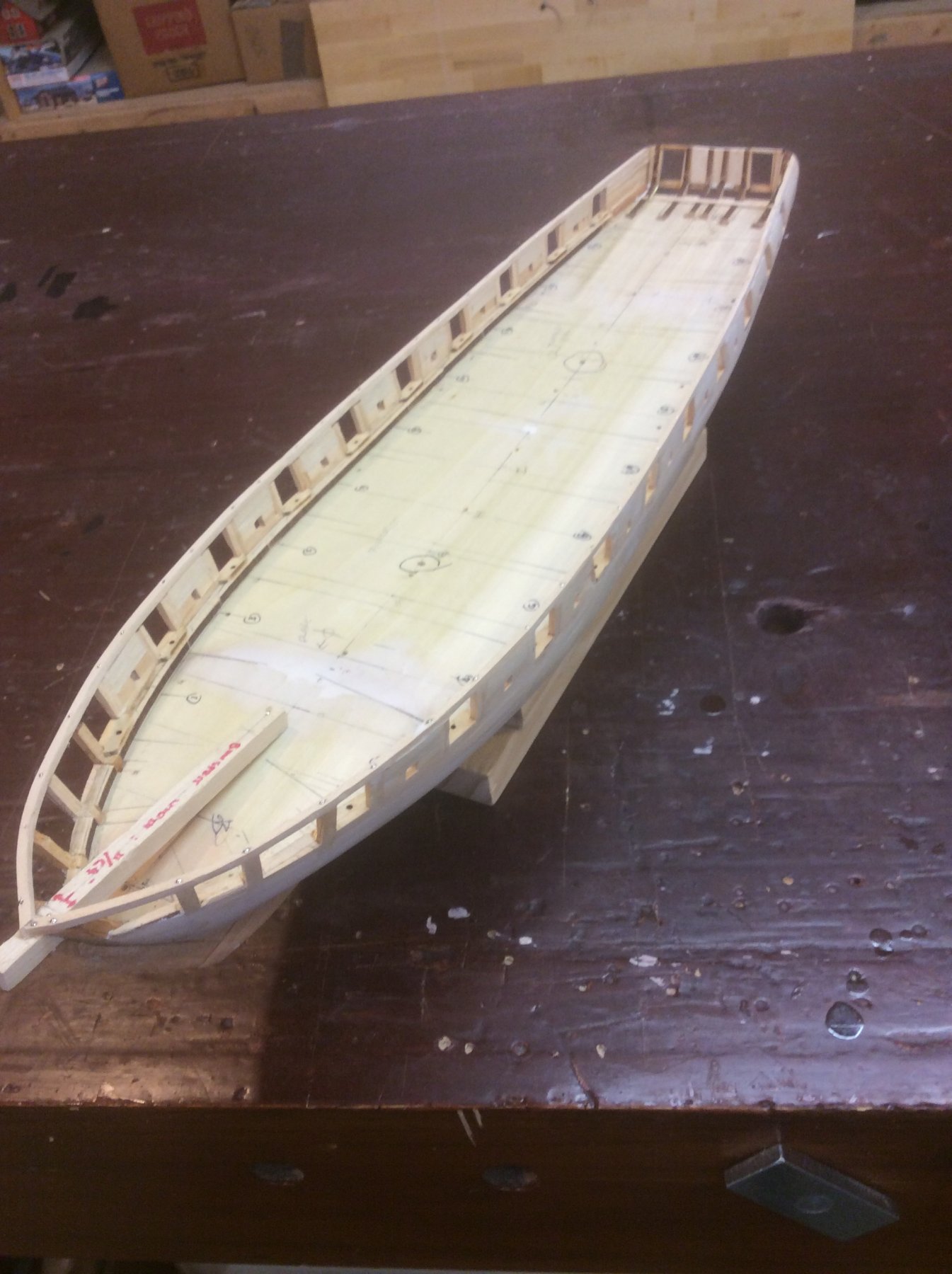
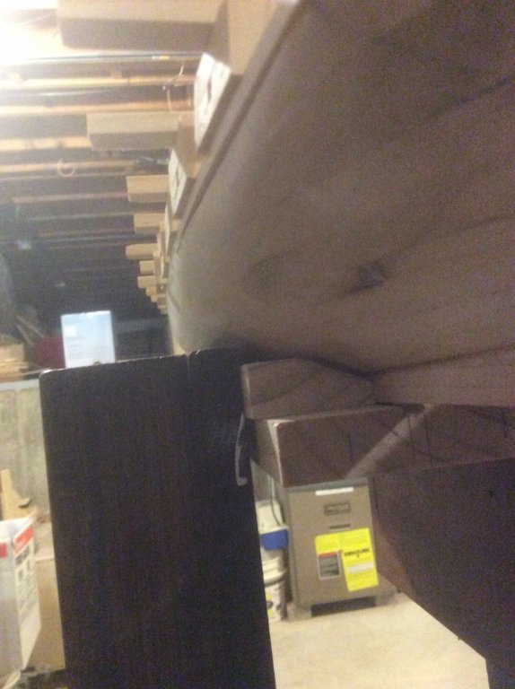
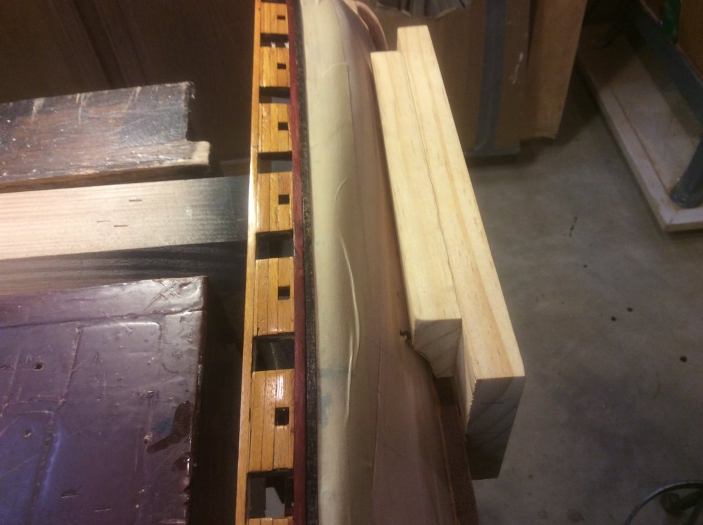
Modelerbob: Thank you. Yes, exactly to my point : Considerable debate. Mtaylor: Pic below is how I secured my hull while working topside during an earlier stage of the build. At the expense of three or four small screw holes in the hull, I get almost absolutely secure support in a bench vice for all the work ahead. Might even be able to use the holes in a future display mount. I think the only major hull attachments will be the channels and chain plates, which can be reinforced with pins or small dowels driven deep through the bulwarks, and other attachments made the same way, driven into the solid hull under the planking (I have the luxury of not having to hit individual bulkheads; also, the space between the exterior bulwarks planking and the ceiling on my model is solid wood). Although I still intend to scrape away the finish and use adhesive, as well. lmagna: Fortunately, I don’t think I’ll need the bleach, now, but will keep the thought for future reference (I still have deck planking to consider).
-
Modelerbob: There is considerable debate about what Lawrence and Niagara may have looked like and materials of construction. In spring and summer of 1813, both Brits and Americans suffered severe shortages of men and materials on Lake Erie. Lawrence and Niagara were both constructed of green locally harvested timbers (unlike contemporaries like Constitution and her sisters, which could use materials like live oak from Georgia and Florida). Most materials were either stolen from the Brits, or laboriously hauled overland from Baltimore, and up to Erie, Pa via wagon and small streams. Both brigs were built mostly by house carpenters rather than shipwrights, and even they were directed to not do something unless essential ... they were only intended to engage in a single battle, and not have a long life. Walter Rybka in his book The Lake Erie Campaign of 1813, says: Due to the shortage of oakum, the below-waterline seams of the Niagara and Lawrence were partially caulked with sheet lead. So, I’m of the opinion that Lawrence looked nothing as “finished” as typically depicted in paintings or most models. Of course, that’s speculation, and I’m not making my model as “raw” as I think the may have been. Thanks for the comment.
-
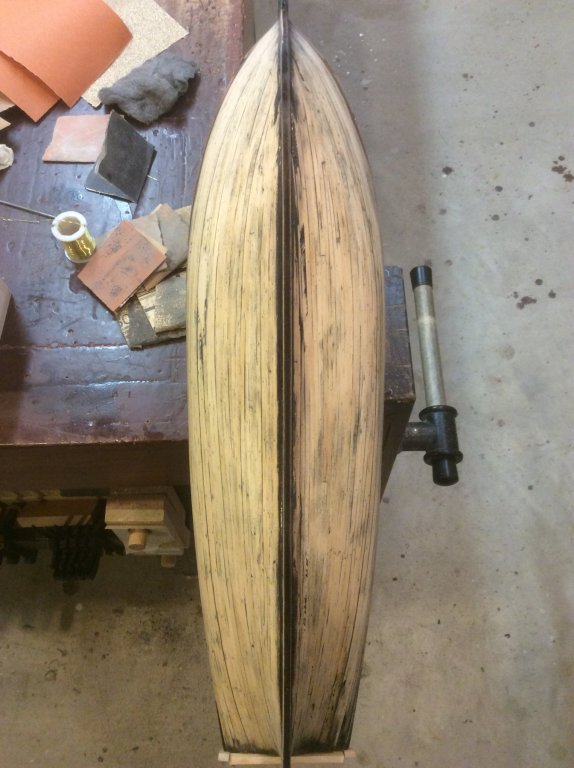
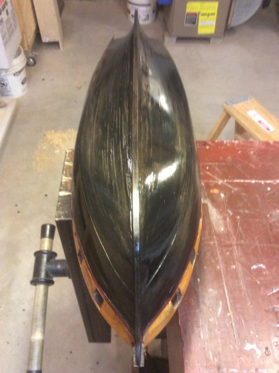
Druxey and hornet: Some of my frustration stems from the fact that I did create a test panel. But, I can surmise several reasons the hull planking differed from the test planking: I can’t say for certain that the wood used on both was from the same board, although both were clear white pine; Altho I used the same proportions, the stain used on both was mixed at different times; Who knows if when wiping down with a cloth I used the same pressure? Finally, the test panel was small, about 2”x4”. Maybe there is a difference in the appearance of small vs large (think: that dinky paint chip against the final color of the living room). Thistle17: I am reluctant to use chemical on my planking, not knowing how they might affect the PVA below. But, I’ll reserve those steps if all else fails. I decided to take the advice of sanding down again. Concerned about how much wood I had left, I probed the planking with a pin and decided that in most places I had more than I thought. So, I brutally attacked with 60 grit sandpaper. Then I worked up with 100, 150, 350, and 600 grit paper and a rub with 0000 steel wool. Then I mixed my stain in a ratio of 4:2:1 ebony, walnut and gray, and applied. Used a dry brush to wipe off excess after drying for ten minutes. Except for a couple blotches near the keel, I got the color I want (put another way, the color I’m keeping). But this model has much more work to go, so, keeping chemical treatment and veneering in my pocket for now, I need to protect the surface against greasy fingerprints and rub off during the handling ahead. I won’t be using TruOil (that’s a lesson learned!). So ... the question now is: Shellac, satin polyurethane, or paste wax? Advice welcomed. Thanks.

-
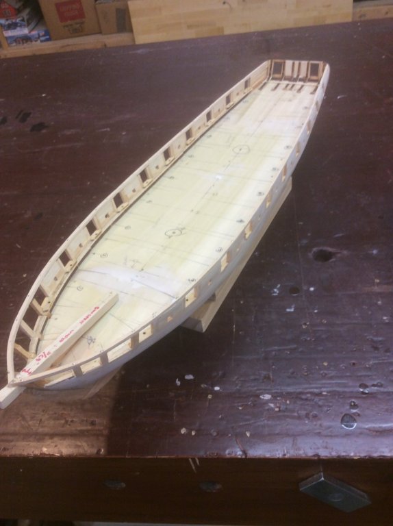
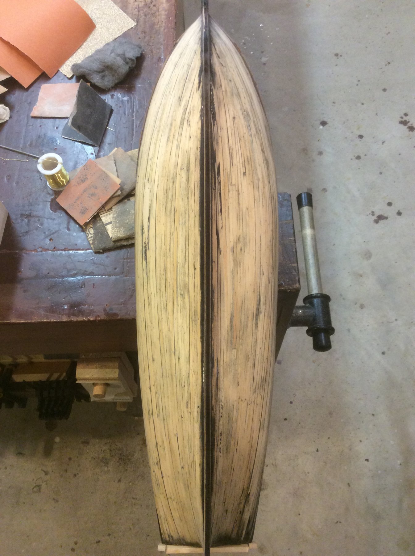
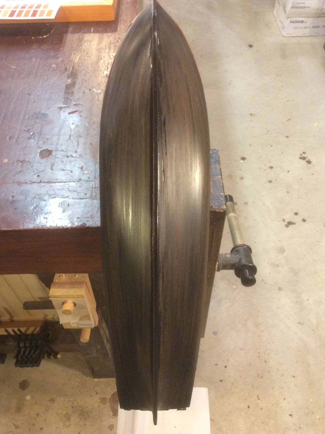
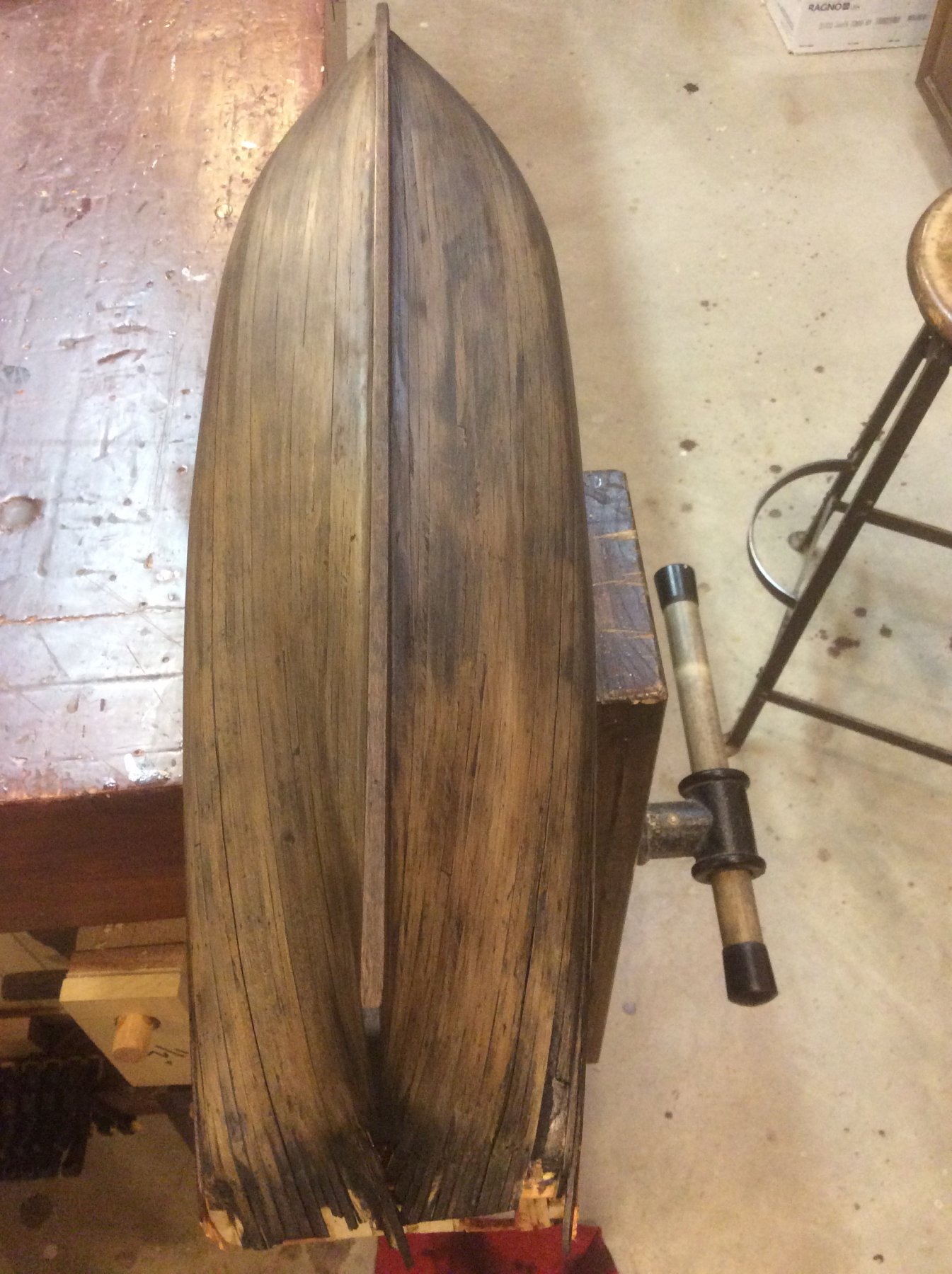
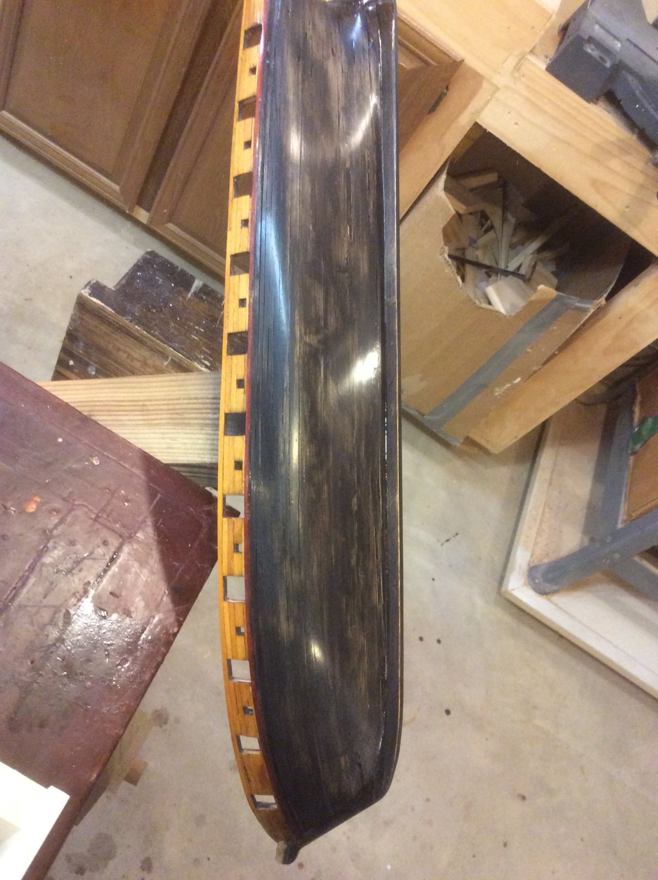
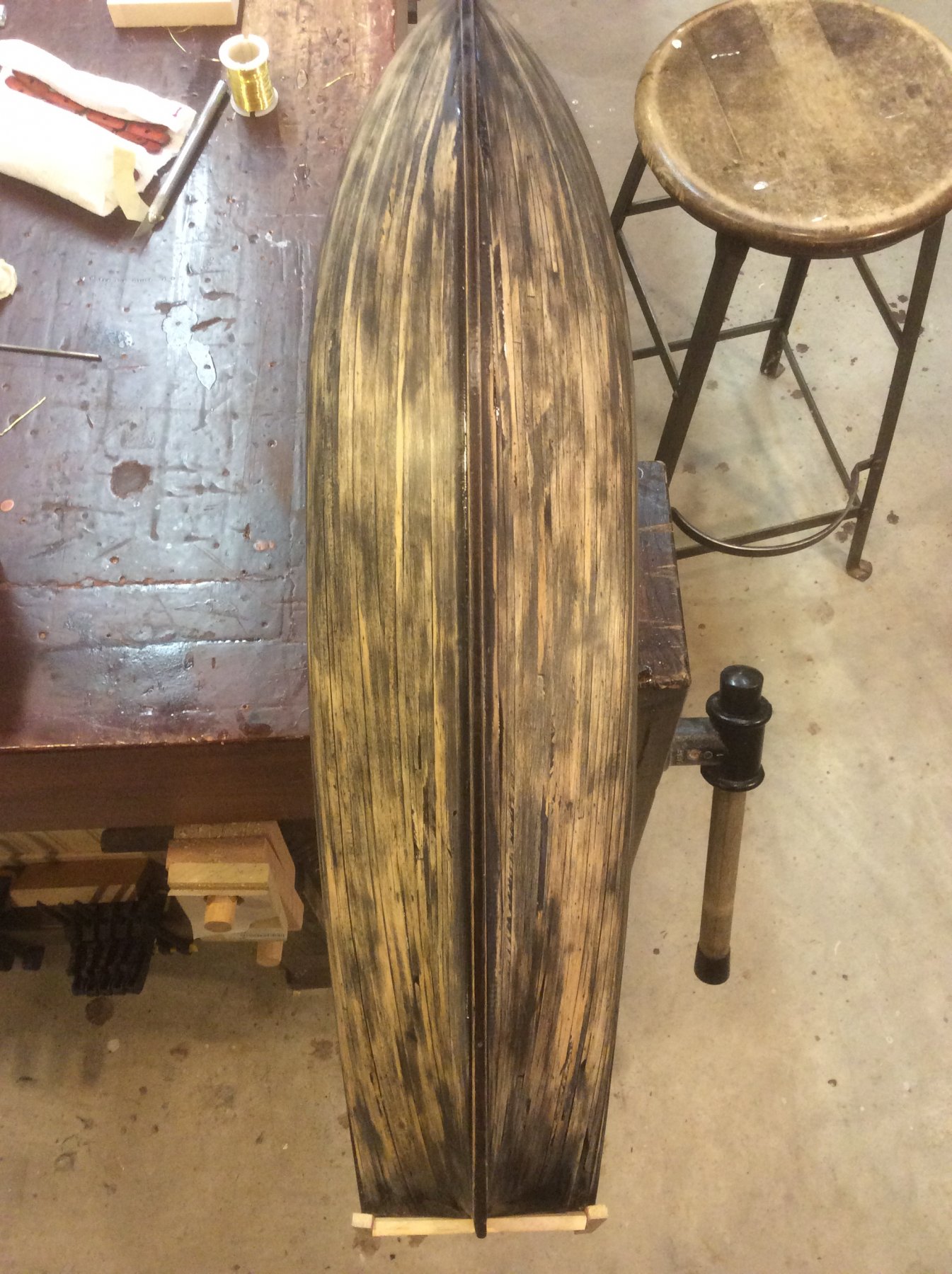
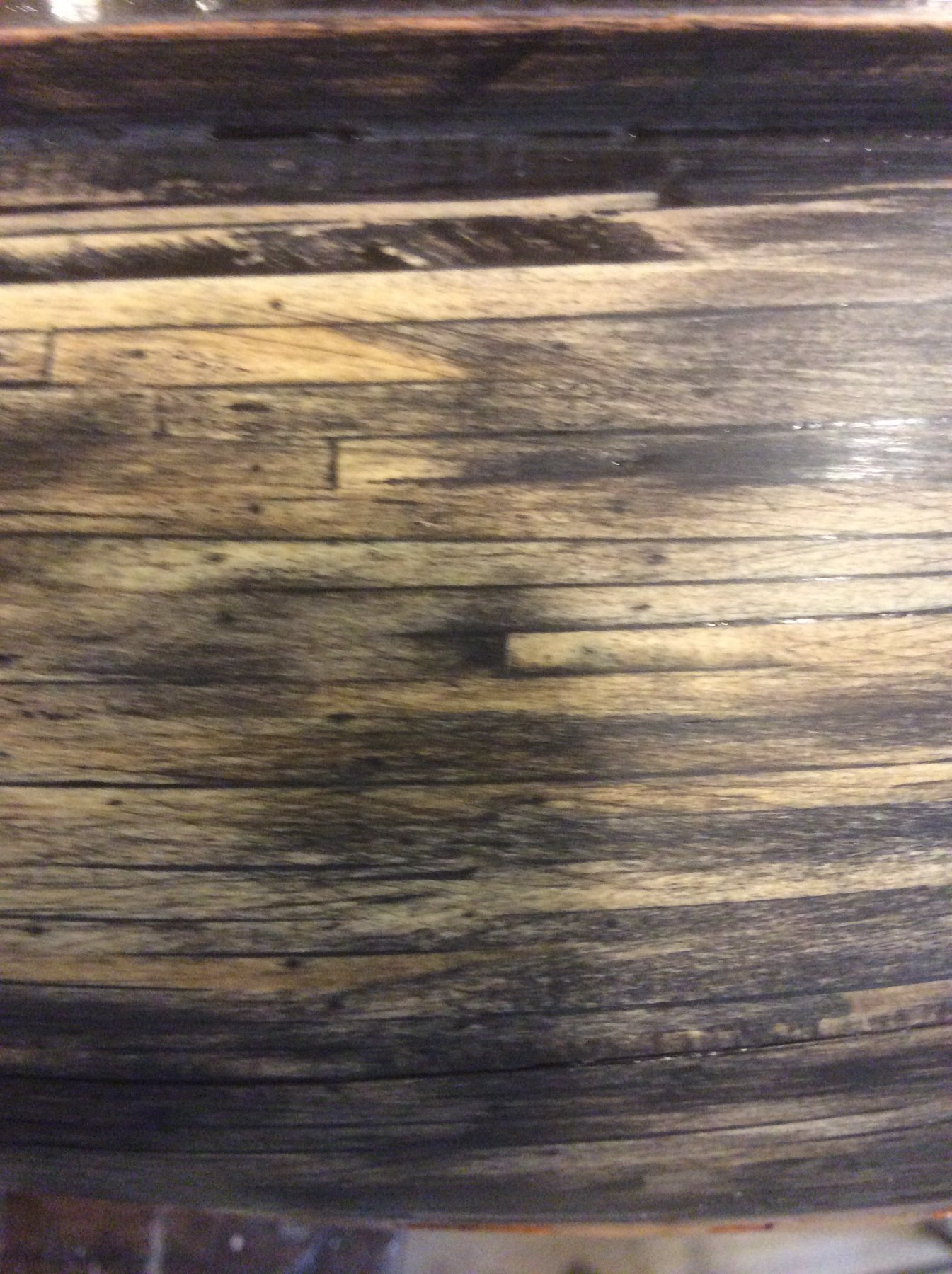
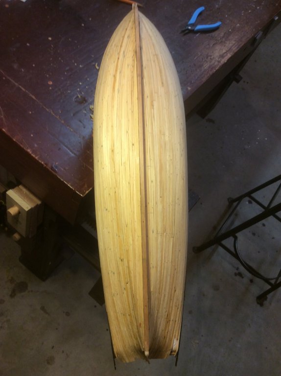
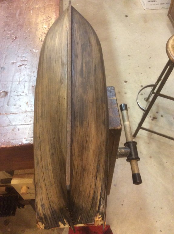
I am modeling US Brig Lawrence essentially from scratch, based on the Model Shipways Niagara kit plans. It is a solid hull, with my first attempt at planking any hull. I am pleased with the way the planking turned out (pic below prior to sanding)... ...but am struggling with the finish. I wanted to achieve several things: I wanted to use pine for the planking since that’s what the original ship was planked with I wanted the planking detail to show thru (otherwise, why go to the trouble of planking ... just paint a solid hull) I wanted to somehow evoke the idea that Lawrence might not have been painted at all, since she was built in what was essentially a wilderness at the time. Maybe these goals are are mutually exclusive. At any rate, I’ve been attempting the finish, and through the process am now at a point that I’m not sure what to try next. After final sanding of the planking, I applied a mix of gray and black stain, and wiped it down. it wasn’t as dark as I wanted, so applied another coat of black stain. This time I waited longer before wiping it down. I was fairly satisfied with the color at this point. I had seen a post by a modeler from Germany in these forums (unfortunately, since removed) of a finish I liked that used a final coat of TruOil. On the exterior planking and the ceiling of my bulkheads I used Osage Orange and Redheart, finished with TruOil, and really liked the effect. So, after staining the hull planking, I applied TruOil. But, it was too dark and too much glare for the hull. I tried to dull it down by using steel wool, but it was still not right. Then I attacked it more aggressively with steel wool and sand paper, taking it down to almost nothing. This is where it stands at the moment. I like the detail that is visible in the planking ... ...but would still like the overall to be darker. But, I have concerns in taking the next step. First, I’ll bet there is still some TruOil lingering in places ... would stain or paint stick? Second, the stain can says do not thin, so I’d have to wipe on and off, which might take off some of what is already there, and be even more blotchy. Third, the spaces between planks are already filling, and if I use some finish that is not transparent, I think I’ll lose the detail. Last, there is a limit to how much I can sand it down ... 1/16” thick planks before they were initially planed and sanded, and sanded again. The second pic above was closest to where I wanted to be, if a bit darker. So, can this hull be saved?


-
First naval engagement US versus British
Srodbro replied to allanyed's topic in Nautical/Naval History
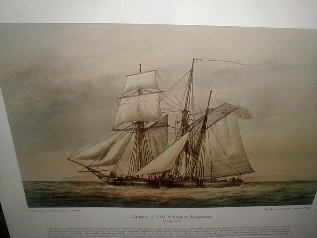
I am wondering if there is any more definitive description of HMS Margaretta and Unity than in these paintings, which appear to be contradictory. The first doesn’t depict any square rigging on Margaretta.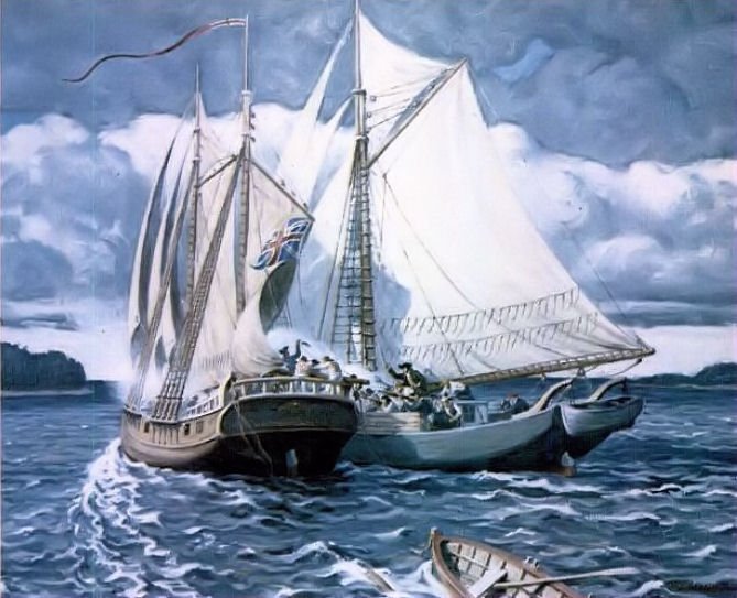
-
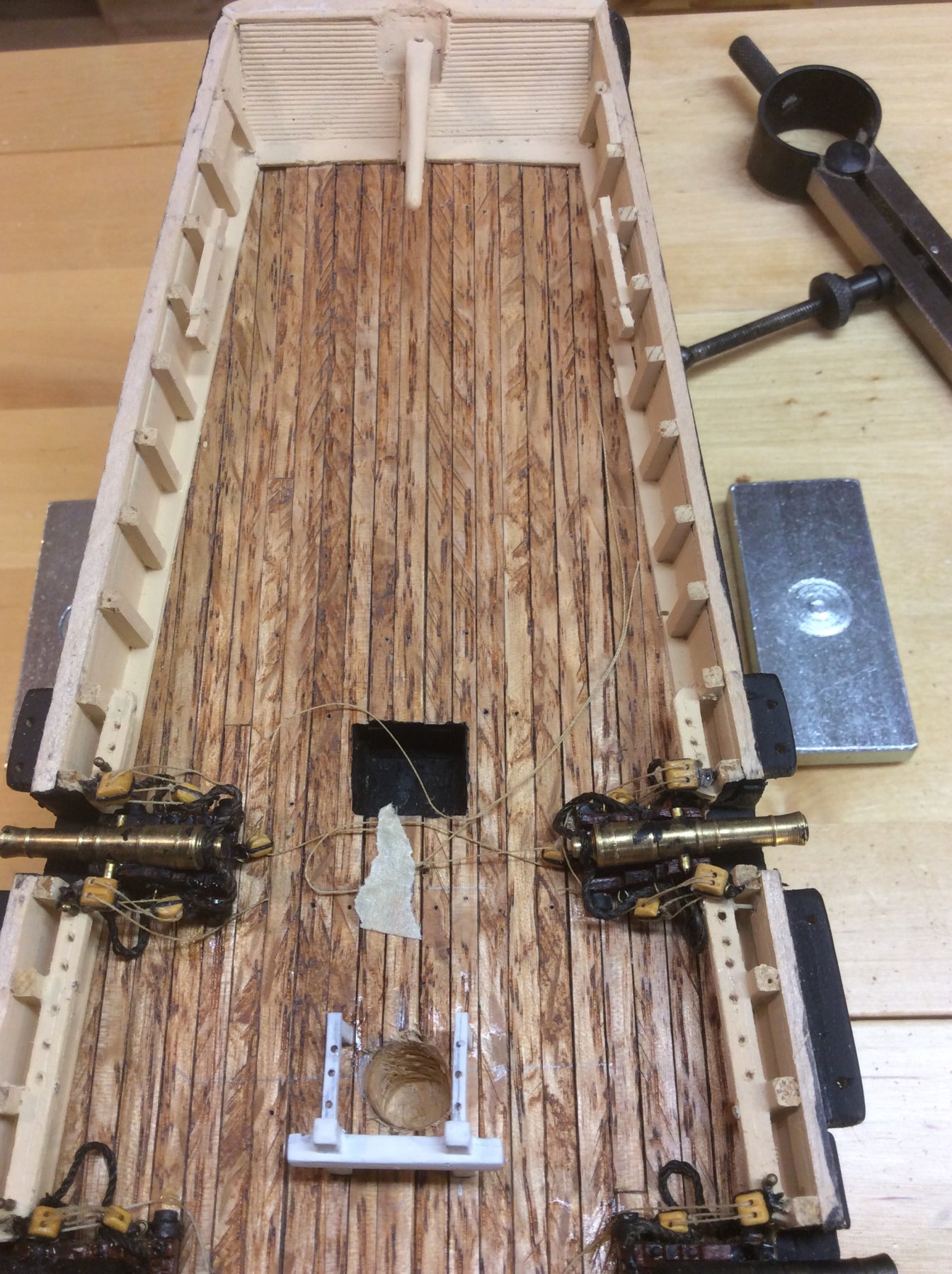
Yes, I have. For deck planking. And I agree that the grain is very pronounced, but I disagree that you can have "scaled" wood grain. True to scale wood grain I don't think you can possibly discern. As far as appearance, it depends on what you fancy. Although, I admit I'd probably not use it again, once all the deck furniture and guns and rigging are added, it still provides some character and texture to the deck, which otherwise might be flat and dead looking. Not sure I'd plank a hull with it.

-
Just discovered your build log. Glad you're back at it. Looking forward to following. I think I recognize some of the water in the background of your pics!
-
Have enjoyed following your work, and looking forward to updates in the spring. Greatly appreciate your superb craftsmanship and techniques. Thank you.
- 756 replies
-
- 3
-
-
- galleon
- golden hind
- (and 2 more)
-
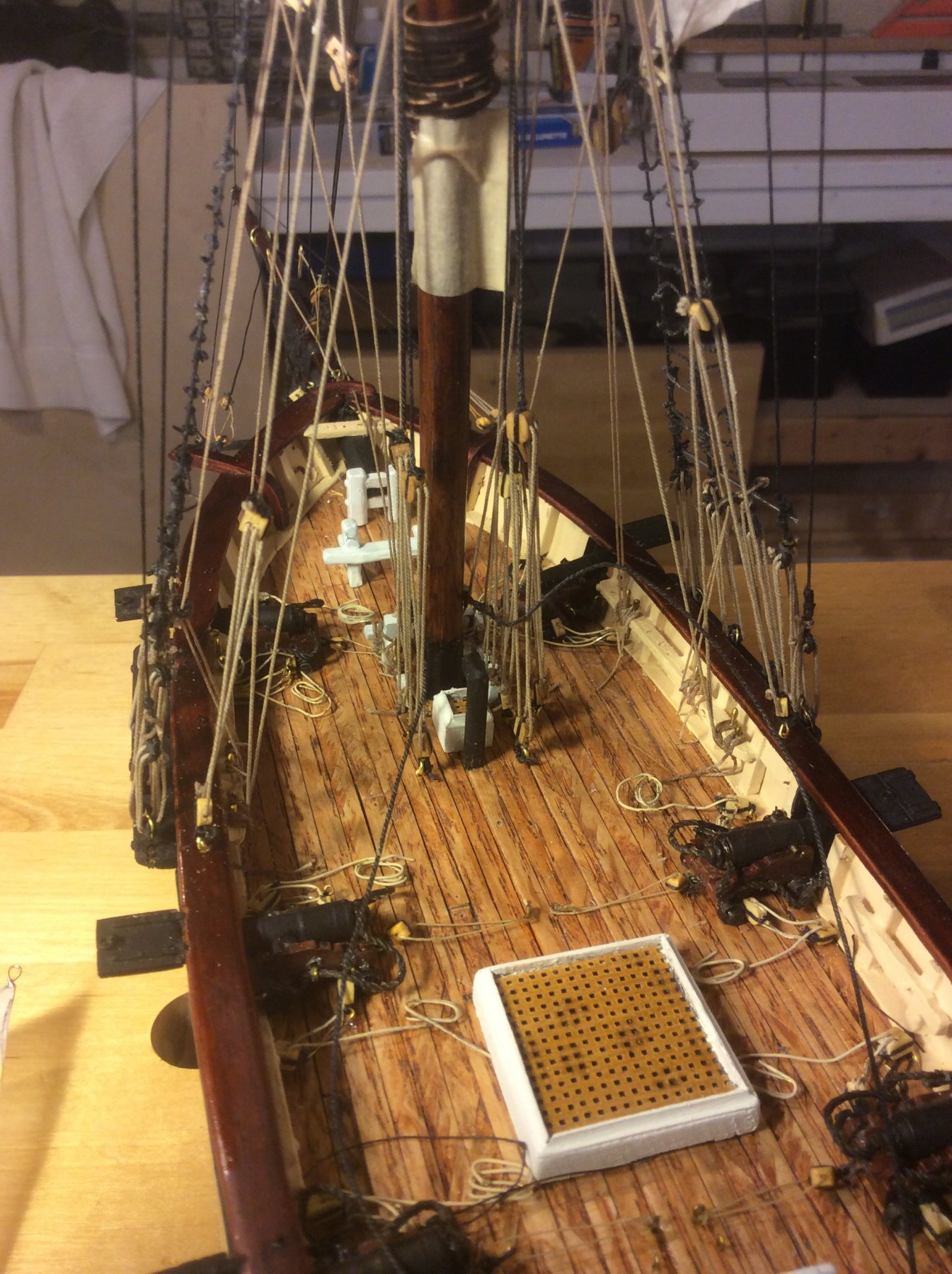
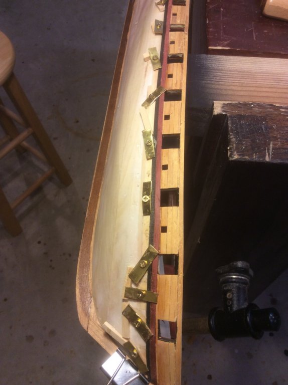
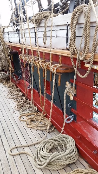
There is a pic posted by AON in the Nautical General Discussion forum of a pinrail on the Niagara, copied below. Notice the black lines run down from the pinrails to the ceiling near the deck. Is this reinforcing for the pinrail? Given the huge forces imposed onto the pinrails by half a dozen lines from the running rigging, I am surprised that this isn't more common. I've never seen this depicted on models. Lacking these reinforcements, does anyone have detail of how the pinrails were joined to timberheads? Must have been one strong joint ... dovetailed with several pins?
-
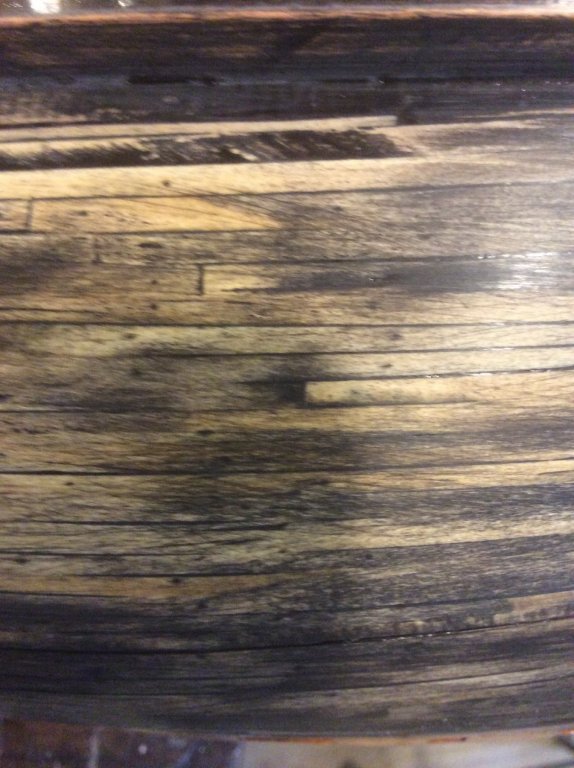
I am fascinated by this ship. I find curious the position of the lowered mast, at its 2 degree skew, appearing to be paralleling the routing of the Reep from the bow to the capstan. Also, in the photo of the base of the mast, there are sheaves thru which I would bet the Reep is reeved. Judging from the drawings, these sheaves would be at about deck level when the mast is lowered. I wonder if, after passing thru these sheaves, the Reep ran up the mast, say to the location of the throats of the gaff, then paralleled the gaff down to the capstan. Doing so would direct a lot of the force from hauling the Reep to the base of the mast, and take some of it off the peak of the bow. The additional complexity of being able to lower the mast must be driven ( in my humble opinion) by some clear critical operating advantage beyond spilling a bit more wind, but I cannot think of what it might be. The skew to the bowsprit, and its apparent ability to be retracted, is also curious. Also, something protrudes from the mast above the five crewmen on deck ( unless, this a photo defect) which excites curiosity. Fascinating!
- 193 replies
-
- 4
-
-
- wilhelmina vii
- fishing
- (and 1 more)
-
Allow me to demonstrate my ignorance with a question. In the fourth photo in the original post, the forward mast appears to be un-stepped, but the rigging of the forestay appears to allow for it. May I ask if this was done routinely, and if so, why?
- 193 replies
-
- 3
-
-
- wilhelmina vii
- fishing
- (and 1 more)
-
Menard's specialty dimensioned lumber (plastic wrapped) goes under the name "Mastercraft". Not sure if that's their own brand, or if there is an independent company out there. They used to stock a variety of species, but now you have to special order walnut and cherry and mahogany. They seem to usually have poplar, hickory, maple and oak.
-
No worry: She lives in a glass case, so is protected from the admiral and grandchild. My only concern is how she'll age, if the sails will get brittle and crack on there own.
-
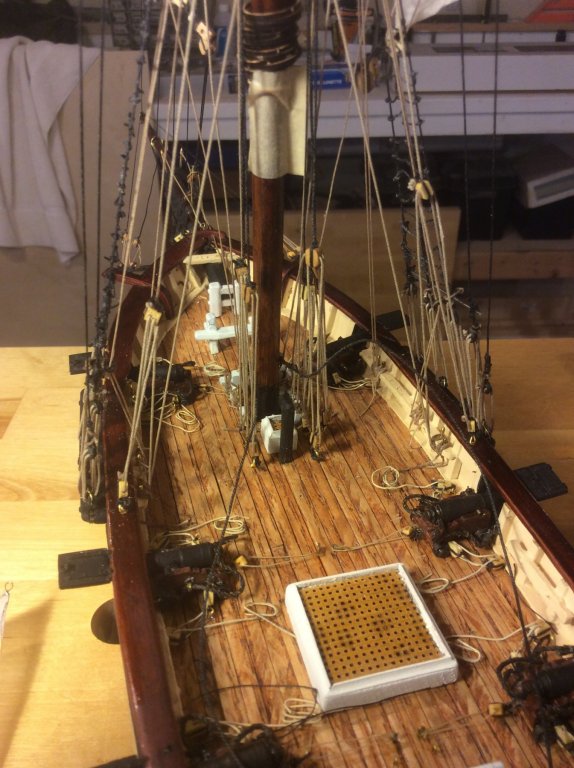
Hmmm....the gremlins are throwing in out of sequence pics again. To make up for that, here are a couple of the model as we go into mothballs. Thanks for all the comments along the way. Will be back to continue this project.