
Supplies of the Ship Modeler's Handbook are running out. Get your copy NOW before they are gone! Click on photo to order.
×

Tigersteve
-
Posts
1,316 -
Joined
-
Last visited
Reputation Activity
-

 Tigersteve got a reaction from Keith Black in Cutty Sark by My Fathers Son - Restoration
Nice!
Steve
-
 Tigersteve reacted to My Fathers Son in Cutty Sark by My Fathers Son - Restoration
I have finished with the boats for the time being as I can now access them and add any finishing touches at the proper time.
I did buy a book Ship Modelling Simplyfied by Frank Mastini but have fallen foul of the Electronic world. Actually have a book, you know, those things that have shhets of paper bound up between hard covers, you would read a section, work on completing the task and then move on to the next section. I think I need to charge up my old Kindle as this is still possible with that, but using the Kindle App on my phone is not. The point of this is getting jobs done in the right order. While Frank has told me to complete the Futtocks and upper shrouds, I have gone ahead and started the main shrouds and that is going to impede my work on other rigging tasks and installing the Yards, so I am putting that on hold for the time being.
The reason I had started this was to add stability to the Masts, I have glued these, but they are stil a little unstable.
I carried out an Audit on what Yards had survived and it appears I was missing 4. Also, they are not necessarily the most accurate in sizes, but I have decided to go with these as they were dads work. A lot of cleaning up was required and one of the larger yards, the Lower Top Sail Main yard was badley warped. 30 minutes in hot water and then clamped overnight to a metal ruler has cured that problem.
So, I am now making the missing 4 and then converting the fittings on them to match those in Harold Underhills Plate no 18 to get the metal work into some semblance of what should be. I am not going to be able to do Sheaves so I wil have to improvise on this.
This image is the Yards for the foremast. I still have to recreate the Royal, but the Upper Topsail Yard has been recreated and fitted out. Lessons learned here are Antiqued Brass Wire makes more realistic Bands than sheet Brass and are easier to make, and Pi is an important number to calculate the size of the blank.
I have to admit that this took longer than I envisaged, but the effort will be worth it when they are installed on their Mast.
Simon
-
Tigersteve reacted to My Fathers Son in Cutty Sark by My Fathers Son - Restoration
So boat 1 now has 4 oars, mast and gaff. Just needs rowlocks, lifting eyes and fittings for rigging for mast/sail.still need s a rudder as well.
-
Tigersteve reacted to Papa in Charles W Morgan by Papa - FINISHED - Model Shipways - 1/64th scale
Building a fife rail. I was surprised there where no castings other than the 3 stanchions
-
Tigersteve reacted to WalrusGuy in Figurehead of the USS Confederacy (1778)
Looks amazing! Are you planning to sell these?
-
 Tigersteve got a reaction from JpR62 in Lowell Grand Banks Dory by Tigersteve - FINISHED - Model Shipways
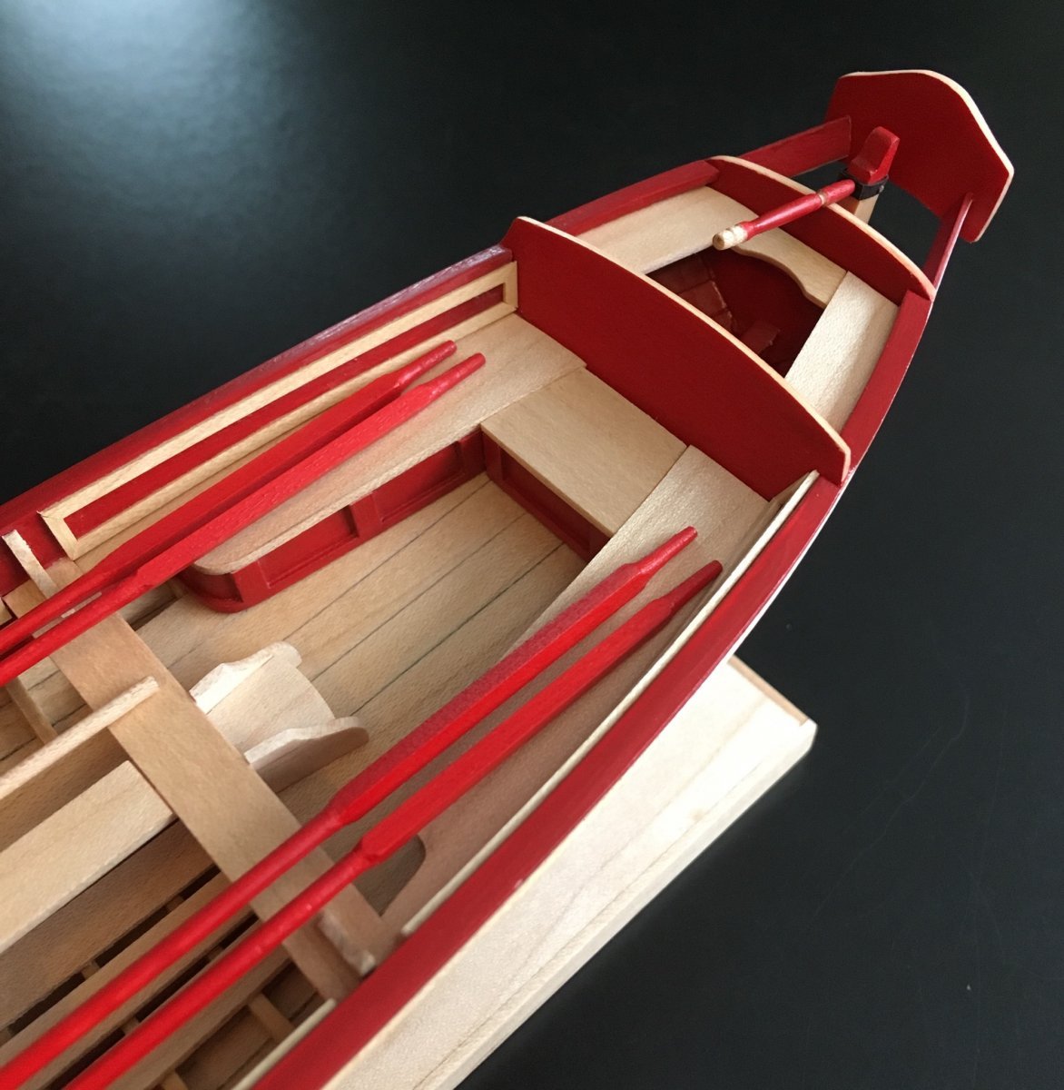
Finishing the paint job on the buckets took a while. White and green paint were mixed in different ratios to get the desired hue. The final coat was the lightest version of this mixture, followed by a damp brush while the paint was still wet. This removed most of the last coat to create the texture.
Holes were drilled in the buckets and the thwarts were permanently installed. Next, I will work on the oars.
Steve
-
Tigersteve reacted to Blue Ensign in Queen Anne Royal Barge circa 1700 by Blue Ensign - FINISHED - Syren Ship Models - 1:24 scale
Thank you Nils,
They are an eclectic mix of sitting figures purchased from Deans Marine.
Having separate arms and torso helped the 'conversion' to Royal Watermen of the early 18th century.
Unwanted detail was removed using the Dremel, and the tunics were added using Artists modelling paste, Milliput, and styrene strip.
These stage photos give you the idea.
3257
3388
3283
Regards,
B.E.
-
Tigersteve reacted to Vladimir_Wairoa in Glory of the Seas 1869 by Vladimir_Wairoa - FINISHED - 1:72 - medium clipper
Back to stern sheer etc. Kicked myself to that finally. ..upper molding missing but its final shape ...
-
Tigersteve reacted to WalrusGuy in USF Confederacy 1778 by WalrusGuy - Model Shipways - 1:64
I started planking the ship. I can already tell, I'll be doing this for quite a while!!! 😅
I am enjoying the process though, and taking my time gluing each plank.
Here is the jig I used to bend the planks:
Then I started planking. The first two strips were held using these clips:
When reaching the stern, there were some tight corners which I had to manually hold for the glue to set. I put on a Netflix series and watched for 30 mins to help speed the process mentally 😁
While planking I noticed the starboard sweep ports were not positioned correctly, so I took out the template again and noticed a 0.5 cm difference! Good thing I was planking each side systematically to notice this. Also, the first two starboard sweep ports are positioned 2 mm above where they should be located. This will be an easy fix which I will resolve as I plank the 5th layer..
And here is where the ship is at currently; on the fourth layer of planks:
-
Tigersteve reacted to Blue Ensign in Queen Anne Royal Barge circa 1700 by Blue Ensign - FINISHED - Syren Ship Models - 1:24 scale
Whilst I await the arrival of my next project I have continued to play around with more Watermen figures to people the barge.
After much faffing around I decided on six figures as this seemed to give the best balance on the boat without giving an overcluttered look.
The figures as with the original oarsman are all derived from various 1:24 scale figures from Deans Marine.
In setting the figures the trickiest part is fixing the oars in the vertical position. I had to resort to smearing ca on the palms of the rowers to secure them.
I didn’t wish to mar the varnished thwarts, so a thin strip of Blu-tac was used to secure the oarsmen in place.
3422
3423
3413
3425
3438(2)
3437(2)
3411(3)
3398
3401(3)
I think I can now declare the model finally finished, time to clear the workroom for the arrival of Sphinx.
B.E.
16/08/2021
-
-
Tigersteve reacted to Nek0 in Le Soleil Royal by Nek0 - 1/72 - Marc Yeu
Thank you very much for your messages !
Julia is growing up and will turn 1 year in a few days, it's been a very busy year between the family and the Covid but I could resume the work on the model a few days ago and I ended the third deck panels. I won't give up !
Thank you for your support, I really appreciate it !
-
.thumb.jpeg.4963596e313aceb66fe9ac8717a80c04.jpeg) Tigersteve got a reaction from Mike the Maxx in Lowell Grand Banks Dory by Tigersteve - FINISHED - Model Shipways
Tigersteve got a reaction from Mike the Maxx in Lowell Grand Banks Dory by Tigersteve - FINISHED - Model Shipways
Finishing the paint job on the buckets took a while. White and green paint were mixed in different ratios to get the desired hue. The final coat was the lightest version of this mixture, followed by a damp brush while the paint was still wet. This removed most of the last coat to create the texture.
Holes were drilled in the buckets and the thwarts were permanently installed. Next, I will work on the oars.
Steve
-
Tigersteve reacted to Chuck in HMS Winchelsea - FINISHED - 1764 - by Chuck (1/4" scale)
If you recall I didn't take any construction photos of the stove the first time around so I had to build another one. This will allow me to complete the 8th chapter.
Step1....Assemble the four 1/8" cedar pieces that will become the foundation for the stove. Note the bottom "B" in the photo. The two larger pieces are glued to each side of "B" so the ends are flush. The final smaller piece is glued to what will be the aft end of the stove. The top edges are flush. Sand all edges flush and there is no need to remove all the laser char but the fore and aft surfaces should be sanded smooth for painting black later.
Step 2 - Glue the aft face (1/32" thick) onto the aft end. The top is flush. Note how the bottom edge hangs lower a bit. That is by design.
Step 3 - Glue the 1/32" thick sides into position. Make sure you orient them the correct way. Note how the aft edges and top and bottom are flush. Sand them smooth with fine 320 grit sandpaper.
Step 4 - Glue the top into position. Sand all edges and corners flush. Once again be careful to glue it on in the correct orientation.
Step 5 - Glue the grill into position. Outside surface is flush with the side edges.
Step 6 - Although indicated as step six because I built it in this order...I know realize that the above step should be done after you complete steps 7 and 8. It will just be easier. So skip ahead and then return to step 6. In this step the two larger platforms are glued into position followed by the lids for the pots. This is pretty easy as you just have to follow the laser etched outlines. Sany them smooth for painting.
Step 7 - Glue the strips around the perimeter as shown above. These are thin so be careful. Add the three lengths for the legs first keeping them even so it wont wobble. Then add the cross piece along the top edge. The edges are flush as you can see. Sand them flush after you glue them. Dont worry about the laser char as the whole thing will soon be painted black.
Step 8 - Glue the doors into position. Dont worry about the laser char. You can also see above that I glued the two halves of the hood together so it can be shaped and sanded smooth.
Step 9 - Glue the round vent you see on the top of the stove. You can also see the hood has been shaped. It was sanded free of char and smooth. The front edge of the hood has a slope aft. This needed to be sanded into the hood. It is not a very severe slope but you should check the plans for details. The hood was laser cut a bit wider than needed to leave you room to sand it for a nice fit and all squared up.
Step 10 - Glue to more of the round pipes on the front face as shown to simulate the drains. No need to get fancy here as these will be nothing more than a shadow once installed on your model.
Step 11 - assemble the stack and drain pan. Get them ready for painting. The short ends of the drip pan were glued on first followed by the long sides. The stack is laser cut with very thin sheets ....but they are really not thin enough to look in scale. So you should at least sand the walls along the top edge much thinner to make them look in scale and more fragile. Not the whole stack but just gradually sand the sides tapered so it has the appearance of being much thinner sheet metal. This would be a great time to paint all of these parts as well. Go ahead and paint the stove and these two other pieces black. Keep the surface smooth and free of brush strokes. Sand regularly between coats as you finish up the remaining details.
Step 12 - The stove has its first coat of black paint. At this stage you can glue the laser board hinges onto the stove for all of the doors on each side. Then paint those black as well.
Step 13 - Its going to look a bit messy now because its hard to not see all of the dust on the black painted surfaces. But ignore that for now and press on. Glue the two brackets onto to stove as shown. Line up the square area of the bracket with the other one you already glued on each side. Center it so there is equal distance on the top and bottom of the tiny squared area already on the stove. Keep these brackets lined up on both sides and level. They are very delicate so be careful. Then there is one last tiny square or should I say rectangle of laser cut wood that is also glued to the top of the squared section of each bracket. This finishes the simulation that the brackets are sliding through these small clamps on the side of the stove, Paint them black when done.
Note that I also cut some 19 gauge black wire to length which will span across the brackets. I glued the tiny disc to one end of the wire as shown above. Then I also line up all the pieces for making the pulleys. The pullies are made in three layers. The center layer is very fragile so be careful.
Step 14 - To assemble the pullies...glue one of the discs over the top of those in the center layer. Tey outside layers are slightly larger than the center layers. Then repeat this process on the other side. These discs on the outer layers will simulate a pully nicely. Just remember to keep the holes for those pulleys lined up. See the photo below whic shows the entire assembly completed.
Step 15 - Glue the pulley assembly onto the other end of the long 19 gauge wire you made earlier. You will also need to cut a shorter length that will be inserted in the smaller pully of the assembly. See above.
Also not that because you may build your stove slightly different than someone else, I have laser cut three sets of "center layer" pulleys. The top one on the sheet is the longest. I used this one. But you may have to use one of the other sizes depending on how you do in the next step.
Step 16 - You must drill a hole into the side of the hood. The shorter wire on the pulley assembly will be inserted into it. Depending on where you drill this hole will determine if you need a shorter or longer pulley assembly. So place the pulley on one of the bracket arms to get a sense of where you need to drill that hole. I ended up drilling it dead center (left to right) on the hood but slightly lower than center (up and down). If that make sense. You can also use a shorter pulley assembly and place it on the next level above on the bracket arms as well. You have many possibilities.
I have also started to take care in finishing the black painted surfaces properly. Sanding the rough spots with 420 grit and repainting. I have also used some weathering powder as well to make it look like metal.
Step 17 - 24 gauge black wire was used to shape the handles for the pot lids. I drilled out the holes in the lid deeper and test fit the handles carefully so the black paint wouldt be damaged. I had to bend the wire a few times into the handle shape so it was the correct length so the holes lined up. The stack was also glued on top as you can see.
This finishes your stove. There are many more details you can add but that is up to you. The stove will end up being only partially visible below deck. So take your time and make sure the painted surfaces are smooth and painted with care.
On my stove for the model I added some wire to each side along the top edge. This was sometimes used on the stoves to hang pots and pans and utensils. But the stove is very fragile so this is an optional detail. I used 25 gauge black wire. There were also eye bolts with rings along the top edges in some cases which were used for the lifting the stove. Again ....you can get crazy with the level of details. But below deck you will be disappointed with how many of these details will ever be seen. So rather than risk breaking it or over doing it, I concentrated on "neatness" and making a well crafted and painted stove. These close ups are pretty brutal but this is a tiny fitting actually.
Ample amounts of weathering powder were used on all surfaces once completed. The powder achieves two things. First when using a rust or brownish tint it makes the whole stove look more like metal. But most importantly, the entire stove was coated with an ash or grungy black powder first. Every surface. The powder really smooths the surfaces out and covers up the brush strokes etc. ....It makes the surface smoother to a degree but all care should be taken to have a smooth painted surface ahead of time. I used the grimy grungy black powder first. Then I followed that up with some rust powder. I tried not to over do it with the rust because you dont want it to look too "rusty". You just want to use it to define certain areas. You can see the difference in the surface quality as my stove assembly progressed. With each new photo I spent time working on the surface quality and applying more powder. I also sprayed the entire stove lightly with Dull coat before adding a final layer of weathering powder.
As this was my second stove I wont go crazy. I just needed to have construction photos for you guys. Just take your time. It took me 14 hours to assemble the stove and finish it as you see it in the above photos. I also learned that it is very very hard to take pictures of a solid black object so you guys can see the details, LOL.
Shown on the model. But remember the fcastle deck isnt done yet so you can see how much of the stove is actually seen.
-
Tigersteve reacted to Doug McKenzie in Leon by Doug McKenzie - FINISHED - a beautiful little brigantine
We are a little further on towards completion. The windmill pump is installed just forward of the mainmast. I should mention that some time ago we had a question of whether Leon had a windmill pump. We know now she definitely did because of a newspaper article at her demise and because Norwegian maritime law required she have one.
The white card on the back of the starboard main shrouds is used to get proper spacing of the ratlines and rat boards.
When the ratlines are finished we'll add the braces and be done.
-
Tigersteve reacted to archjofo in La Créole 1827 by archjofo - Scale 1/48 - French corvette
Ratlines for the topmast shrouds
The topmast shrouds were thinner than the lower shrouds (comparison on the model: Fore mast shrouds ø 1.08 mm / fore topmast shrouds ø 0.66 mm), their ratlines are also to be made with smaller diameters in proportion, which is the result of earlier research.
Some time ago, I tried to clarify whether the required eye splices could be made with a thickness of ø 0.25 mm. For this purpose I made a splicing tool with a smaller diameter ø 0.8 mm, as shown in the next picture.
The fake splice (2x sticking through) with a dew thickness of ø 0.25 mm was already quite successful at that time.
In the following picture you can see the comparison of the ratlines thickness again.I don't like the simpler alternative version with knots, because it is too thick and doesn't correspond to the original version.
In the meantime I have found the time and muse to make these filigree ratlines with the fake splice directly on the model. It has to be said that this is an extremely difficult job, but it can be done. In my opinion, the result speaks for itself. In this respect it is worth the effort.
But now we will continue with mizzen topmast stay. I still have to find out how it was attached.
I would be very grateful for any information.
See you soon ...
-
Tigersteve reacted to Vladimir_Wairoa in Glory of the Seas 1869 by Vladimir_Wairoa - FINISHED - 1:72 - medium clipper
How did i make grooves.
I must say i still somehow struggle with molding grooves. Finally i think i found a way that satisfyingly brings baswood almost to 95 percent od boxwood with no fuzzies. Well IT Will never match IT but....
How did i go.
1. Slight TRIM of edges with 270 grit.
2. Thin line with scraper.
3. Widenijg line with thicker point of scraper.
4. I Made sharpened Stick of hard Wood but blanded tip of IT. I run IT as last and here are the pics. Those are pretty macro so by eyesight there IS basically no fuzz.
I mušt check how others do IT but fór the moment im Happy.
There IS one smaller 1/3 grooves and one 2/3 fór the glory sheer.
-
Tigersteve reacted to captain_hook in Le Coureur 1776 by captain_hook - CAF - Scale 1:48
Sorry Marcus, just kidding. These iron bands were more time consuming than the barrels itself. There are 5 bands per barrel supplied as photoetched parts. Each band has an overlap of about 2-3 mm, so I used a needle file to reduce the thickness of these overlap about 50% (and also on the other end - opposing side) and soldered these ends together with soft solder - over 50 pieces. Blackened all parts with my favorite blackening chemical (from Krick) and painted the little soldering spots with some black acrylic (they won‘t be seen anyway because all soldering spots are at the bottom of the barrel).
The bands are slightly smaller than the diameter needed, so pushed the bands about 1 mm into their final position.
I made 10 barrels altogether but not sure if I will use all of them because they might block your view while viewing into the side of the ship.
Now I can‘t go further because I have to wait for the ordered wood first. Stay save.
Andreas
-
Tigersteve reacted to lraymo in Norwegian Sailing Pram by lraymo - FINISHED - Model Shipways - 1:12
Just now getting back to work on the sail! I was nervous, but using some tips from the various blogs, its turned out ok so far. Used Mod Podge to coat the sail fabric (instructions said to use watered-down glue, which is what Mod Podge claims to be), and it worked out well. Also, realized too late that someone had mentioned pencil marks are hard to erase after coating. So now I have a few permanent pencil marks. So far, so good. Next is tackling all the rigging. I will need to read the instructions a few more times, as I'm still not sure about it, and I'll need to revisit some of the blogs to get a feel for what needs to be done!
The sail is complete!
-
Tigersteve reacted to WalrusGuy in USF Confederacy 1778 by WalrusGuy - Model Shipways - 1:64
The lower counter of the stern is now planked! This was my first time trying edge-bending on planks (I had to bend to match the curves of the top of the frames). Here are some photos of the progress of this section:
Here, the red line shows where the edge of the plank should rest. The one I am holding here has no edge-bend.
I used the ironing technique as shown by Chuck in his video.
Here, I glued in some of the first planks:
Cutting the notches out was a bit tricky, but manageable:
The excess planks on either side of the hull were trimmed and faired:
Then lastly, the gun ports were built. I had to align the planks to that of the lower counter. Another tricky procedure... After gluing them in place, the counter was sanded one more time. Here is how she stands currently:
Btw, I am finding this build to be more difficult than I thought (more difficult than the Syren I'd say). Small mistakes can stack on one another and lots of new techniques are needed. But all these translate to new skills, and overcoming the challenges is quite enjoyable! 🙂
-
Tigersteve reacted to captain_hook in Le Coureur 1776 by captain_hook - CAF - Scale 1:48
The barrels are mini-kits sold separately. They are made of a center plywood piece planked with two layers of cherry veneer. These barrels take quite a long time to build because every barrel needs 24 veneer parts to complete. The center plywood piece is assembled first and a piece of cherry veneer with some laser engraving is glued at top and bottom.
Then the first layer of planking is glued on the center piece. There are only 24 pieces supplied so be careful while you bend them. I selected the best ones for the outer layer and used the rest for the inner layer.
Then I gave the first layer a good sanding. Be careful - these layers are only .5 mm thick and are easily damaged. After that I glued the second layer - one part at once - and used several rubber bands to fix the part until glue had dried. As I made all barrels at once this took several hours to complete.
I gave the second layer another good sanding and applied some WOP, now they have to dry first. I will attach the iron belts in the next day, these are made of photoetched brass parts that have to be soldered to shape. A snapshot of all barrels - my crew prefer old bordeaux, keeps good mood.
Stay save.
-
 Tigersteve got a reaction from FrankWouts in HMS Winchelsea 1764 by Stuntflyer (Mike) - FINISHED - 1/4" scale
I’ve said it before. Mike’s projects make you elevate your own work. Just excellent! Thank you for raising the standard.
Steve
-
Tigersteve reacted to Vladimir_Wairoa in Glory of the Seas 1869 by Vladimir_Wairoa - FINISHED - 1:72 - medium clipper
...Bulwark stanchions angles were smoothered and rounder ( as much as All wooden corners...) So i did try to be honest to this idea...
I didnt copy any method looked how its done by model expo but invented my own process how to firmly fasten them. Helped by stringer as my usual friend here...filled holes ať the end. IT was beautiful day ....looks like waterways Will get color soon ! I mušt say there IS something astonishing following almost original process ...so much to learn and so far entire Boat IS wooden. Wow. When i stand a person in scale IT was Mammoth! Thanks for watching comment etc...Everyone have good weekend ! V.
-
 Tigersteve got a reaction from Blue Ensign in Queen Anne Royal Barge circa 1700 by Blue Ensign - FINISHED - Syren Ship Models - 1:24 scale
Very nicely done!
Steve
-
Tigersteve reacted to Chuck in HMS Winchelsea - FINISHED - 1764 - by Chuck (1/4" scale)
Just a quick update. This completes Chapter 8. The carlings and ledges were added to the deck framing. There are mostly carlings which run fore and aft between the beams defining the hatch coamings and companionways. 1/8" x 1/8" cedar strips were used. The long strip was painted red on the sides and bottom like the beams. Then small lengths were cut and fitted according to the provided templates.
Normally you see these morticed into the beams. Yes....you can do that if you like. But as long as they are glued in well and secure that is a lot of work to only be covered completely with deck planking. I just cut them neatly to fit. The two ledges on the forecastle were done using 3/32" x 3/32" strips. In addition, the mizzen mast partner was added which is laser cut for you.
We are now 2/3rds of the way through this project. There will be four more chapters in order to complete the model (not including the barge). Here is a breakdown of what those last four chapters will entail.
chapt 9 - Plank the fcastle and qdeck and remaining bulwarks. Add the cap rail. All the remaining coamings and gratings. A few other minor fittings.
Chap 10 - All remaining deck fittings..... The waist will be started as well with the gangways and stairs.
Chap 11 - Return outboard to add the channels and deadeyes....fenders and swivel stocks. The fancy rails along the sheer of the qdeck and fcastle.
Chapter 12 - Add the 8 pounder guns. The headrails. The stern lantern and other remaining fittings.
That finishes the hull and then a separate barge will be made so it can be placed on spare topmasts along the waist.
Here is a look at the hull with the planking templates (already uploaded here for you). I will start the next chapter with the margin planks and move on from there. Think about how much easier the planking will be this time. The templates are done for you and lining off the hull will be simple. You just have to fold the templates along the deck beams and use them as a ready-made tick strip. Easy-Peasy.