

tlevine
-
Posts
1,940 -
Joined
-
Last visited
Content Type
Profiles
Forums
Gallery
Events
Posts posted by tlevine
-
-
It is wonderful to relive all the great builds from MSW1. And yours is one of the great ones.
-
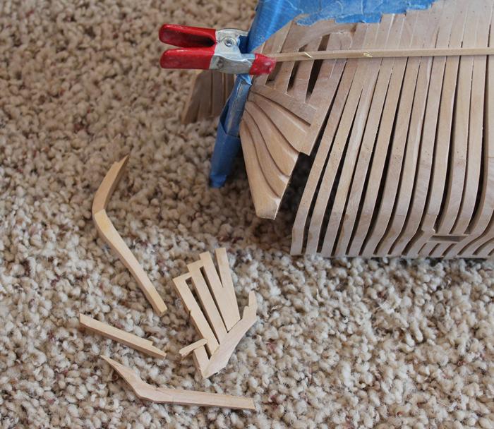
Ben and Christian, thanks for reliving the past with me. Ben, the treenails are bamboo. Specificly, 6" skewers from the grocery store. I look for the packages with the darkest wood. I found that the wood in things like chopsticks was of higher quality (stiffer, straighter grain) but was too light in color.
I hope to have the rest of the log posted within the next week or two.
-
Author: Dan Vad. Now is the right time to make up the pump intakes and dry-fit them into the recess to make sure they fit properly. I also suggest you make up the pump tubes (leave them at least 10mm too long for now) so you get a good idea on whether they fit into the inlets at the correct angles. This will make later fitting a lot easier. Danny.
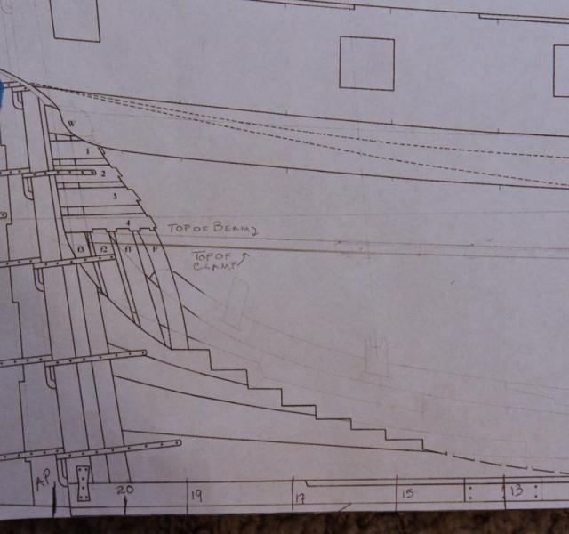
August 27, 2012. In the process of installing the upper strake of the lower deck clamp I looked at Greg’s photo on page 86 of TFFM Vol III. This shows that the top of the clamp extends to the bottom of the second transom. On the Mylar I extended the top of clamp line aft, maintaining the same slight upcurve and it appears that the top of clamp should be below the 4th transom. Danny’s and Remco’s clamp is at the top of the 3rd transom. Mine is at the middle of the 4th transom. I have repeatedly measured using two different approaches and get the same elevation and the line “looks” fair.
Lower Deck Clamp
Author: remcohe. I measured the height of the lower deck from my NMM plans, took the thickness of the beams and the 1” letdown into account and there I marked the deck clamps and it just happened to end on the 3rd transom. I don’t think any of the inner hulls of either build here is the same hence the differences where the clamp ends. RemcoAuthor: Dan Vad. I did the same as Remco and finished in the same position. There seems to be an anomaly somewhere, as neither of us finished on the same line drawn on the plans BUT everything further down the track (cabin bulkheads etc.) fell into place on both our builds. Check the measurement from the top of the clamp to the top of the wing transom. Danny.
August 27, 2012. I measured the height from the top of the wing transom to the top of the clamp and, if anything, I am a hair high.
Author: druxey. There are differences in each vessel of this class. The Mylar was drawn up from the Atalanta’s draught so it may be that the other Swans will spec out differently. The ultimate question is whether the curves fair up properly.
August 27, 2012. After my last post I laid some battens in an X for to aft and everything looks right, so hopefully things will
turn out OK.Author: Dan Vad. I’ve done a check on everything I could lay my hands and here and can’t find an anomaly in yours, but MINE is a bit too high. It’ll be staying that way too. No big deal though – the clamp runs well past the end of the lower deck at the aft end and hasn’t got any beams on it in that area. It’s virtually invisible through the frames and upper deck work as well. Danny.
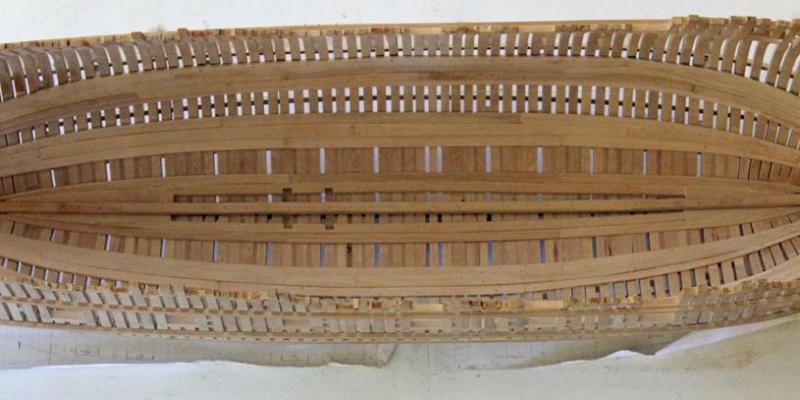
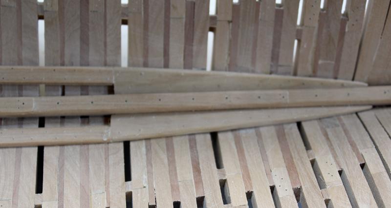
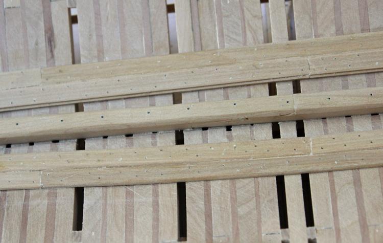
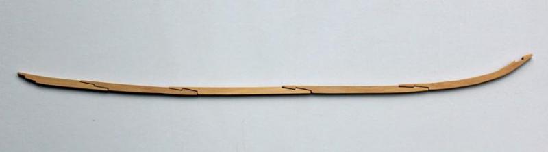
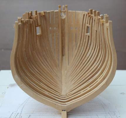
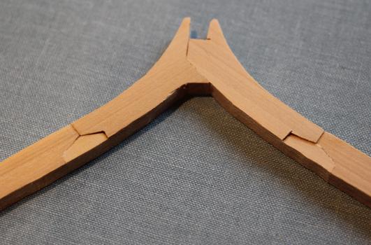
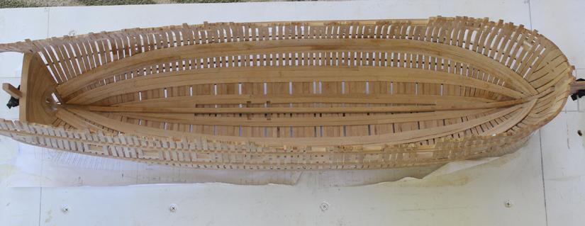
Sept. 4, 2012. I have installed the two lower deck clamp timbers. First, I fixed a copy of the Mylar plan to a plank and used my height gauge to take off the elevation at every other station. This was transferred to the hull interior. Except for the extreme fore and aft stations, the gauge easily cleared the top timbers. Once the height of the top of the clamp was determined, I used a straight-edge with a bubble level glued on to it to confirm that both sides were the same height. (I made sure the building board was level first!) These planks have anchor stock joints for extra strength. I dampened the wood in the last photo to help them stand out. After the planks were installed, I tapered them down from 4” at the top to 3” at the bottom of the run.
Deck Clamp Height
Lower Deck Clamp

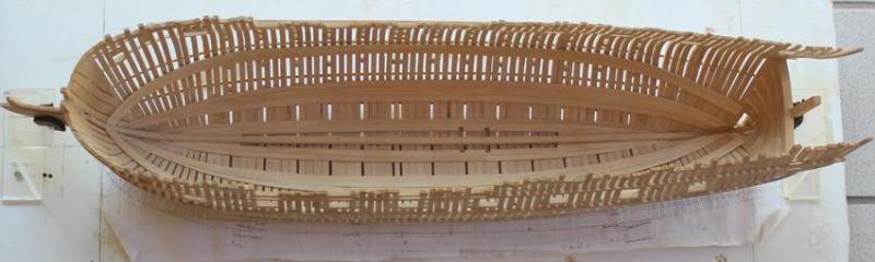
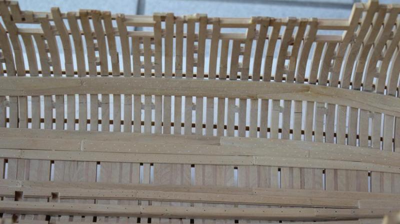
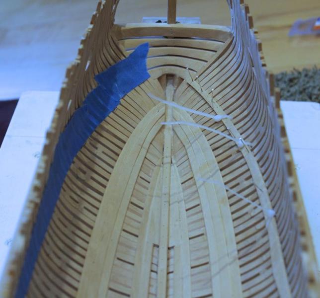
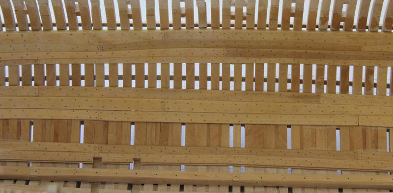
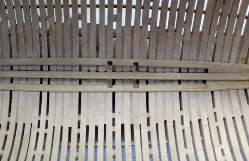
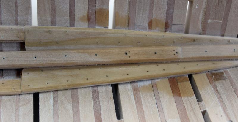
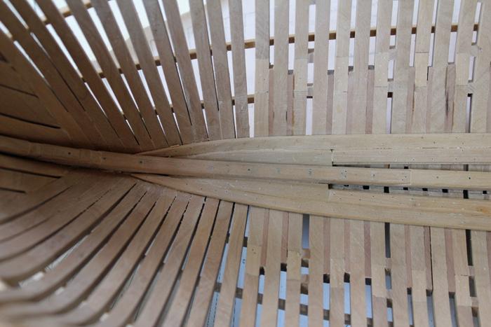
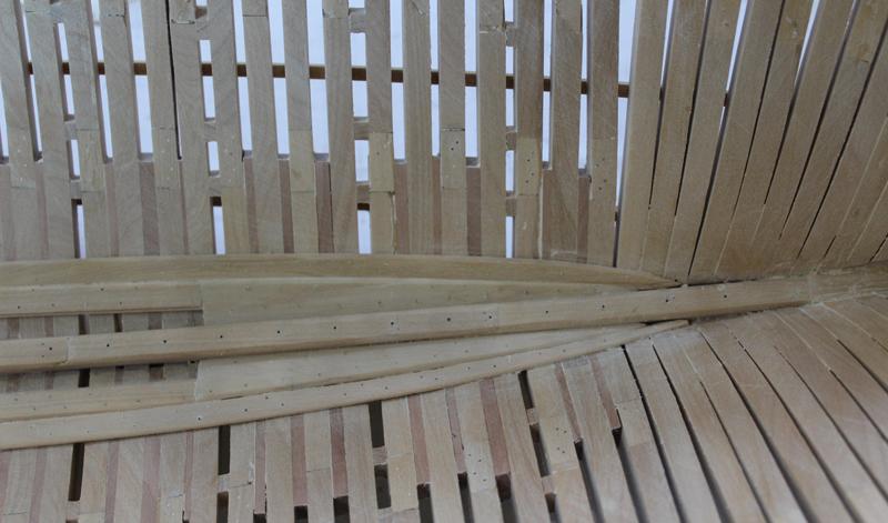
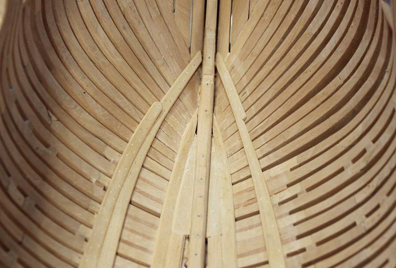
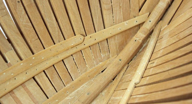
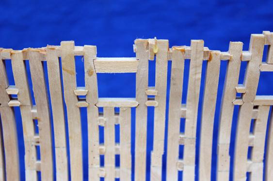
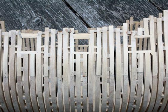
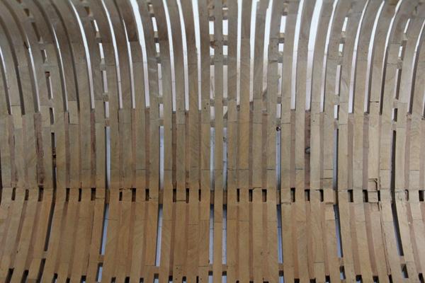
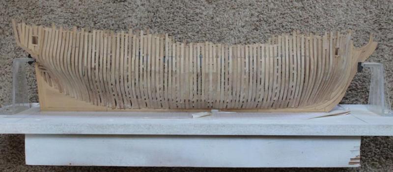
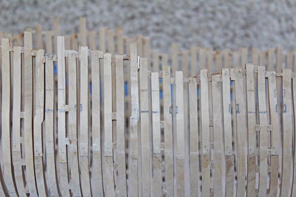
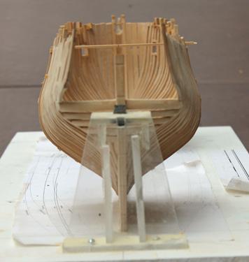
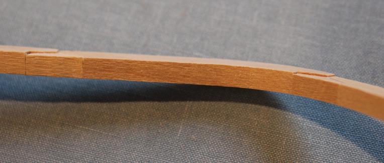
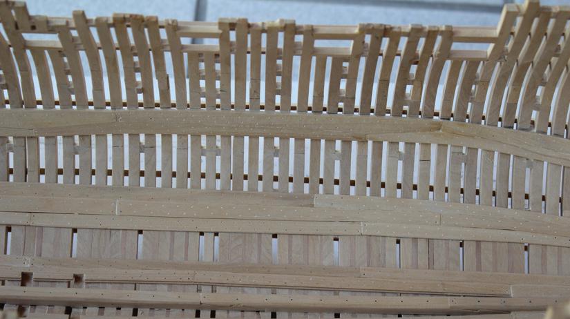
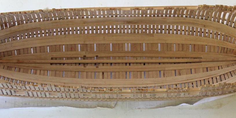
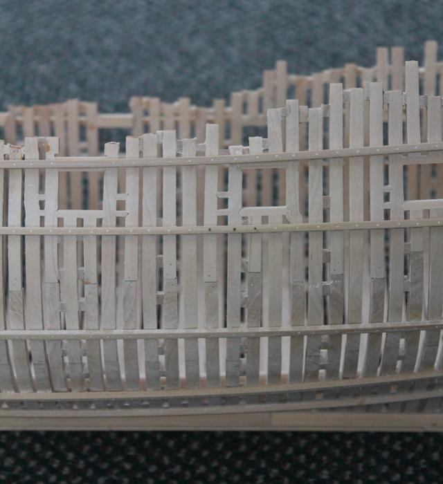
Sept. 24, 2012. I have finally finished the Thickstuff of the first futtock head. After these strakes were installed I put in all of the treenails for the six strakes of planking. There were approx. 2100 treenails to install and it took me almost two weeks to complete them. In the pictures you can see the different thicknesses of the strakes. The top lower deck clamp is 4”, the bottom one starts at 4” and tapers down to 3”. The wood has been moistened to show off the treenails.
Finished Lower Deck Clamp
- PeteB, Elmer Cornish, CiscoH and 3 others
-
 6
6
-
Elia, it is a pain to reconstruct the build log but at the same time it is instructive to review the process and look where I could improve things next build.
-
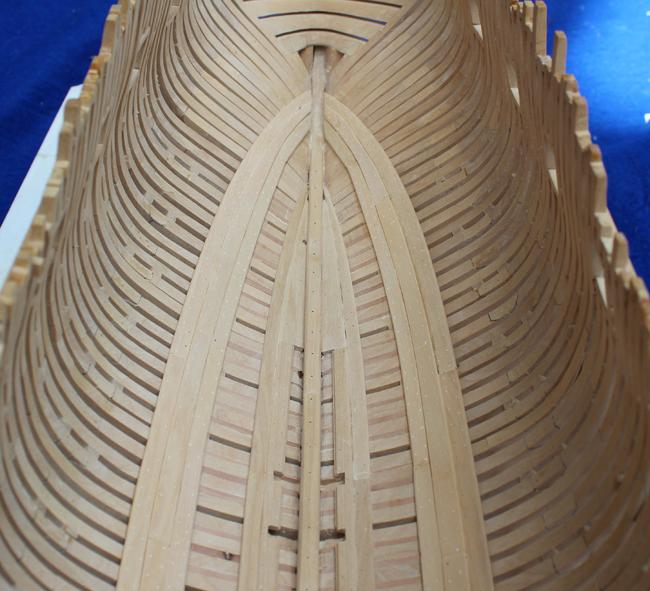
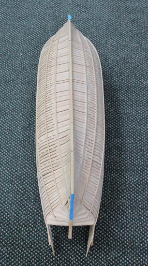
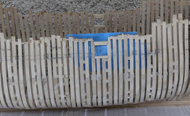
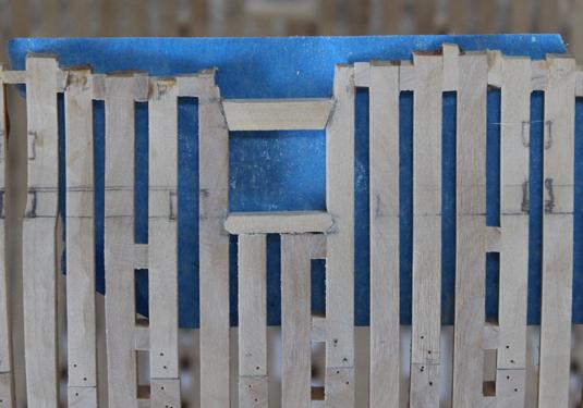
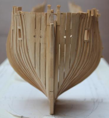
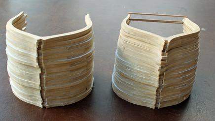
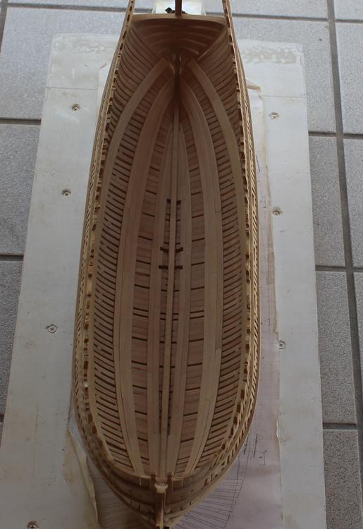
August 5, 2012. I have installed the inner strakes. The inner edge has a rebate for the limber boards and the outer edge is cambered to meet the thinner outer limber strake. I make the rebate by lowering the blade on the Preac saw to 1.5 scale inches. The cut-outs are for the well pumps. The treenails did not stand out well in the photo so I wetted the wood to bive an indication of how they will look after a finish is eventually applied. The apparent gap between the aft strake and the hull is shadowing. You can see the difference in appearance between the keelson bolts and the scarf joint treenails as well.
Inner Limber Strake
August 5, 2012. I will be using Watco’s Danish Wood Oil for my finish. It is very forgiving and gives a matte finish if one coat is used and a low luster finish if multiple coats are applied. I have not seen any change in color over the years .
Author: EdT. Watco Oil is linseed and soya. It will make the wood yellowish and will darken over time. If you want no yellow use an acrylic.
Author: dvm27. The Swan cross section was finished with Watco’s. It does impart a tone to the wood, expecially holly which yellow a bit. The finish is indeed flat after rubbing out. The Echo cross section was finished with General Finishes water based sanding sealer (slightly thinned). The box has not changed color at all, nor has my Pegasus after a couple of years. I would use the Watco’s if you wish a richer color to the wood or the General Finishes sealer if you want to maintain the rough hewn appearance of a new ship on the stocks. Greg. The pictures Greg provided in the original build log were not preserved in the MSW crash.
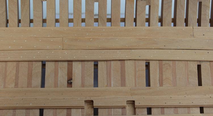
August 6, 2012. The outer limber strakes have been added. Thses taper down from a thickness of 3” to 2” at the fore and aft extremes. As this strake is only 10” wide, the treenails are in a single/double pattern. The inner strake was 12” wide
and so had a double treenail pattern.
Outer Limber Strake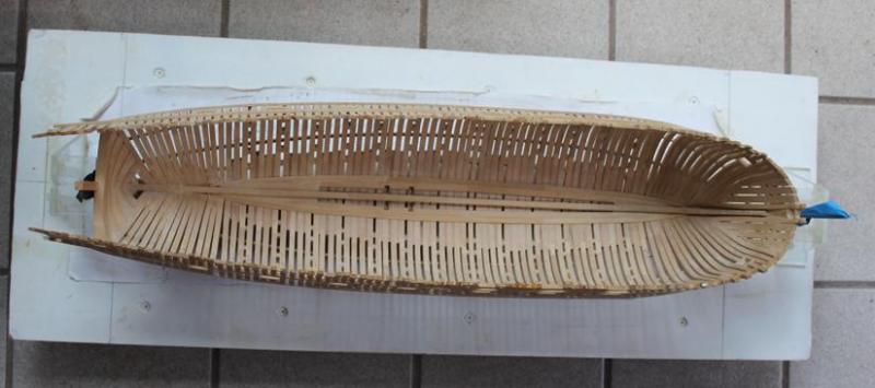
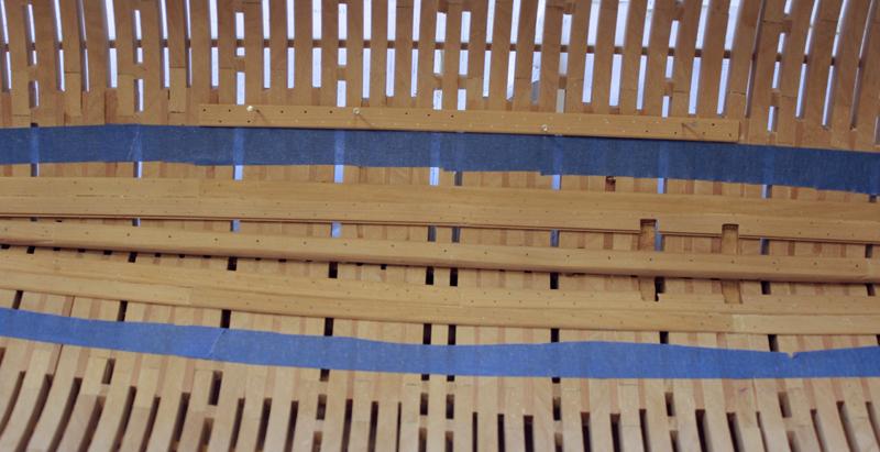
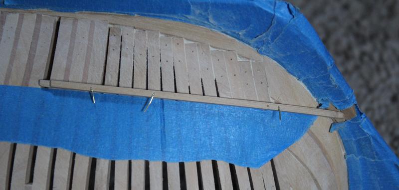
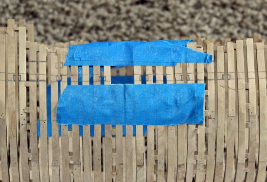
August 13, 2012. The next stiffeners to tackle are the thick stuff at the floor heads. There is an internal planking expansion drawing in TFFM. I enlarged it to full size and know it will be a tremendous asset in determining approx plank shapes. The distances from the outer limber plank to the lower floor head plank are copied from the expansion drawing. I transferred the measurement to the hull and ran my masking tape “ribband” to fair the line. This run of planking is 12” wide and comprised of four planks which taper fore and aft. The foremost plank is cut out to accept the fore end of the middle floor head plank. All of the planks were bent by microwaving them in water, bending them to shape and allowing them to dry overnight. Before installing them, the treenail locations were varked, pierced and drilled. Pins hold the plank in place until the glue
dries. These are blunt 22g pins used for beading. The holes are 24g so the pins were thinned down with a grinding wheel on the Dremel. The lower edge of the planks are cambered since the footwaling is thinner. I have decided to omit the footwaling on the model so as not to completely cover up the internal frames.The middle plank is thicker (14”) and narrows sufficiently in the bow to be dropped. I made a template of the foremost plank with adhesive backed paper and transferred to to the wood. The shadowing in the pictures illustrates the difference in the thickness between the lower and middle runs of planking. The white color in the holes is sawdust. Two bamboo treenails (tan in color) have been fitted in the fore end of the middle plank.
Floor Thickstuff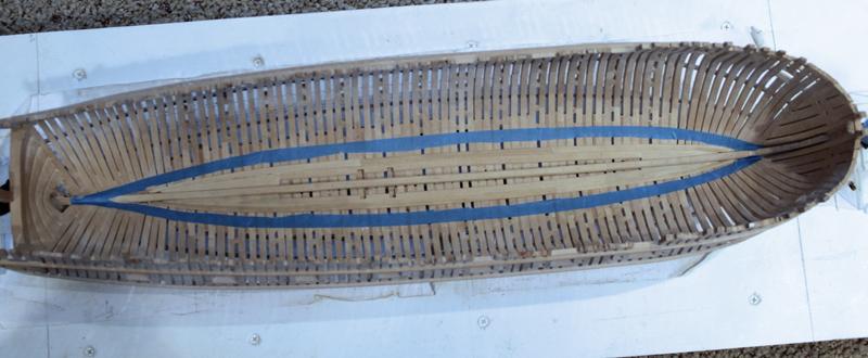
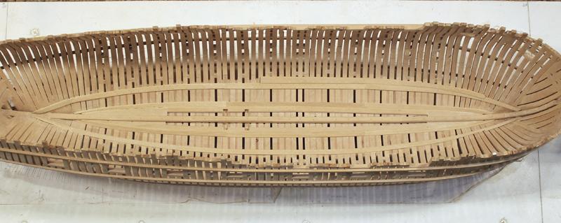
August 19, 2012. I have finally finished the thick stuff at the floor heads. The planks are drilled for treenails but they have not been inserted yet. The middle plank is 1” thicker than the outer planks.
Floor Thickstuff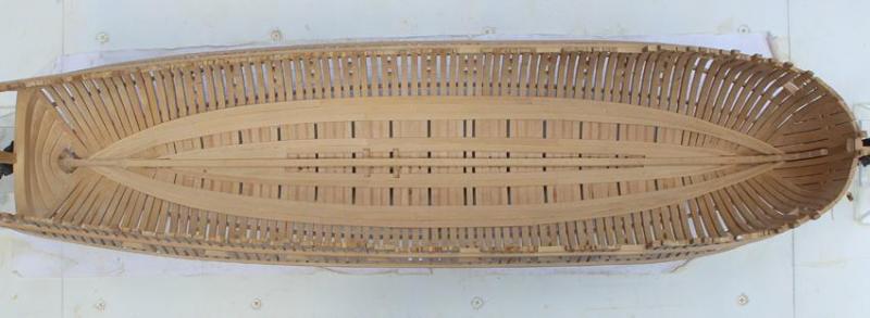

-
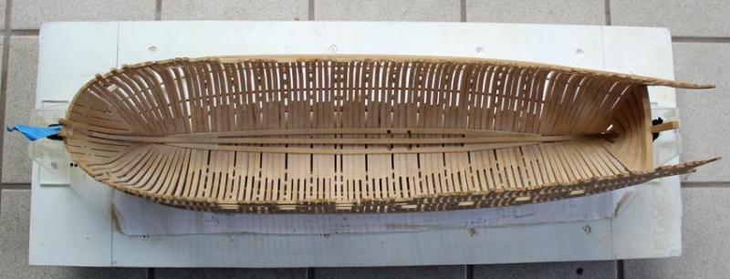
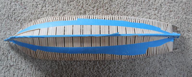
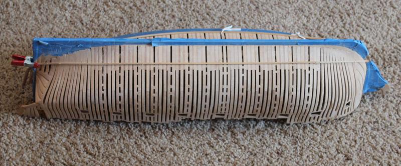
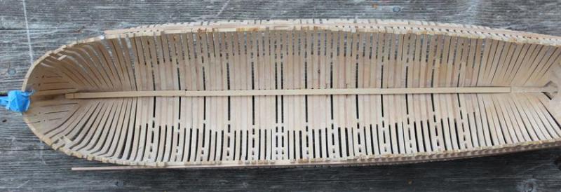
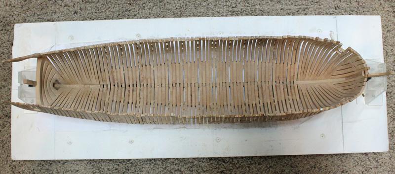
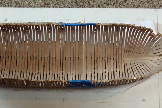
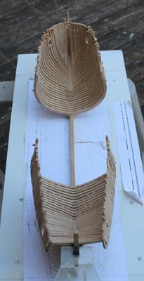
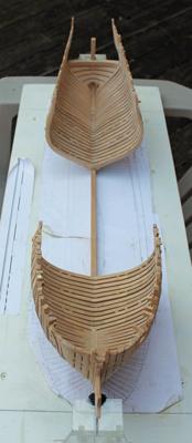
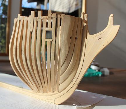
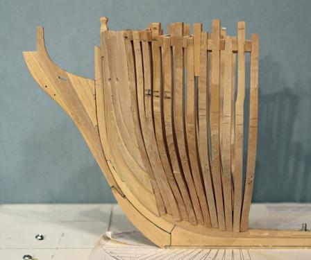
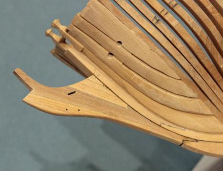
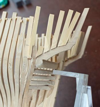
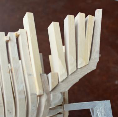
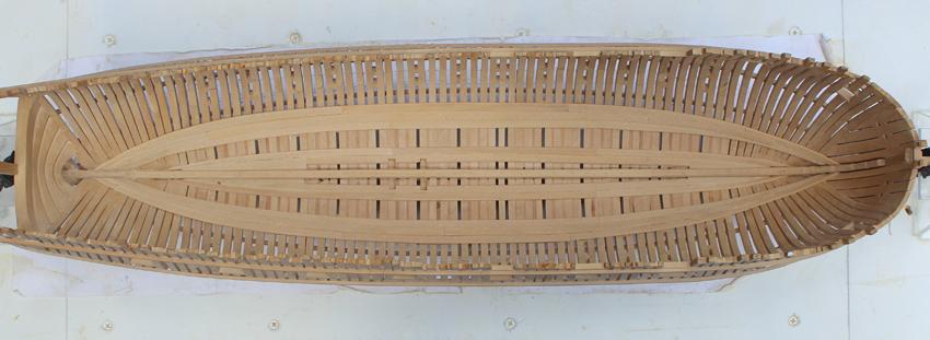
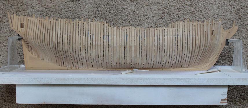
July 16, 2012. The treenails are all in place and the hull has been sanded to 220 grit. I planned on sanding the hull to 400 grit but today I felt like actually building something. (As it turned out, not the best decision I ever made.)
Next on the agenda are the ribbands and harpins. I decided to fabricate these and then finish the sanding prior to their installation. I have yet to decide how much hull planking I will be installing and so the lower four pair of ribbands will be installed on both sides. They can always be removed later and at a minimum provide a bumper for the hull, protecting it from damage. This model travels with me in the car weekly because of my work schedule, so damage is a real concern. From an aesthetic perspective, I am not sure I like the appearance of ribbands crossing through the gun ports, so the decision regarding installation of the topmost ribband will come later. The floor ribbands are located 18” below the floor heads. I have marked this out with masking tape.
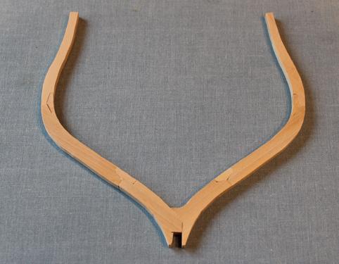
Harpin Run
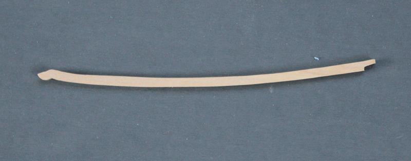
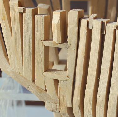
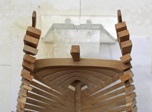
I made the harpin first. This is cut out from 4” stock. Like so many items, this is one that looks deceptively easy but is not. There is the changing angle of the hull to take into consideration as well as the angle at which the harpin abuts the stem. There is a simple scarf aft.
Floor Harpin
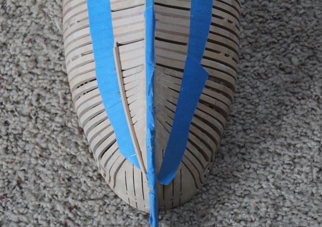
The ribbands are 4” square. I soaked the aft end of the ribband stock to fit the aft hull curve. Both the ribbands and harpins are drilled and nailed at every frame. At this point I have only drilled a few holes and installed some temporary brass pegs.
Floor Harpin and Ribband
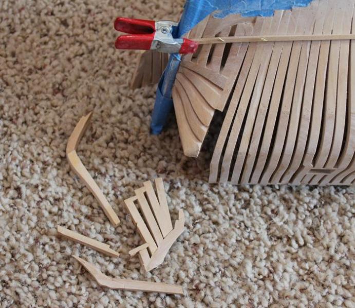
Things were going well and I was thinking of attacking the next pair until…
As I was taking the photos for the build long I repositioned myself and ended up giving the transom a kick in the rear end! Needless to say, I did the only thing an insane model builder could do…take a picture and pour myself a stiff drink!
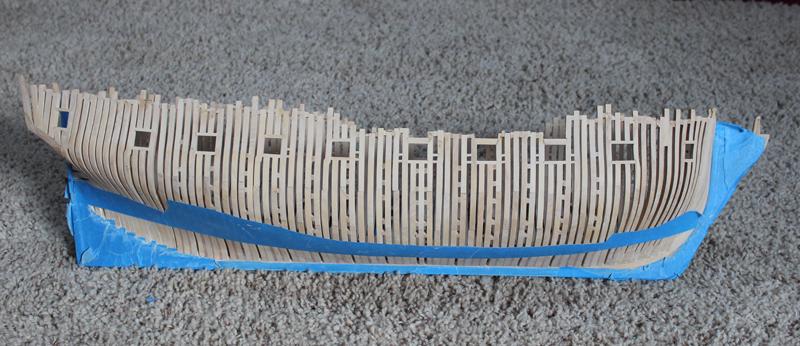
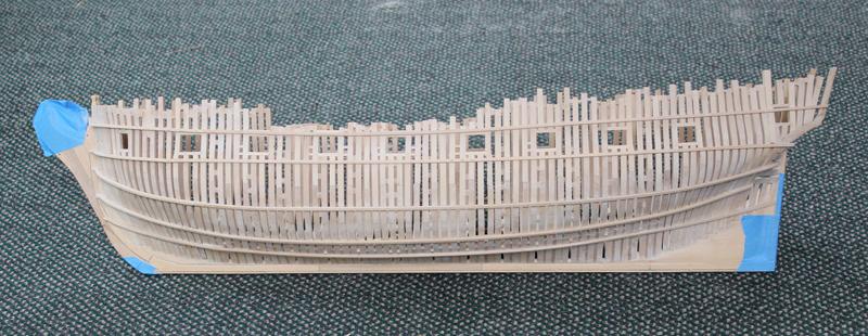
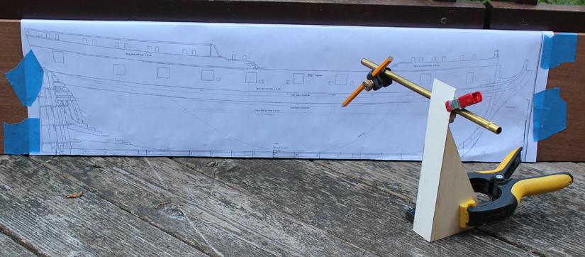
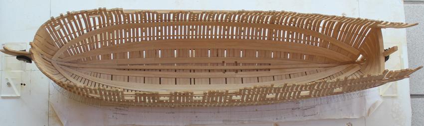
July 30, 2012. I am still working on the ribbands and harpins. These are not particularly difficult to make and install but the sheer number of steps involved means it takes a lot of time. The harpins are made by taking a template of the shape of the hull and transferring the outline to 5” sheet stock. They are actually 4” thick but the excess was sanded off afterwards. I decided to make the ribband a single run of planking to give me the smoothest line. There are five runs of ribbands and although it looks strange to me the topline ribband does run across the quarter light opening.
Once these were in place, they were nailed. There is a nail hole at every frame as well as the hawse timbers and the toe of the harpin. This adds up to approx. 85 holes which must be marked, dimples, drilled and nailed. TFFM recommends 24 g. brass wire which is left proud of the ribband. He suggests rounding off the exposed end of the wire to simulate a nail head. Unfortunately, there really is a difference in the appearance, so 85 holes times 5 runs times 2 sides plus a few extra for screw-ups… Nine hundred nails to make. (These will also be used later in the knees for the deck framing so add a few hundred more to that list!)
The white dots on the ribbands are drill holes filled with sawdust. The black dots are the first three nails.Ribbands and Harpins Completed
July 30, 2012. Scale Hardware sells 0.4 mm headed rivets that will give the right look for the nails. These scale out to ¾”. They are expensive ($10/100) so I am only going to use them where the appearance is critical.- archjofo, Elmer Cornish, Wishmaster and 3 others
-
6
-
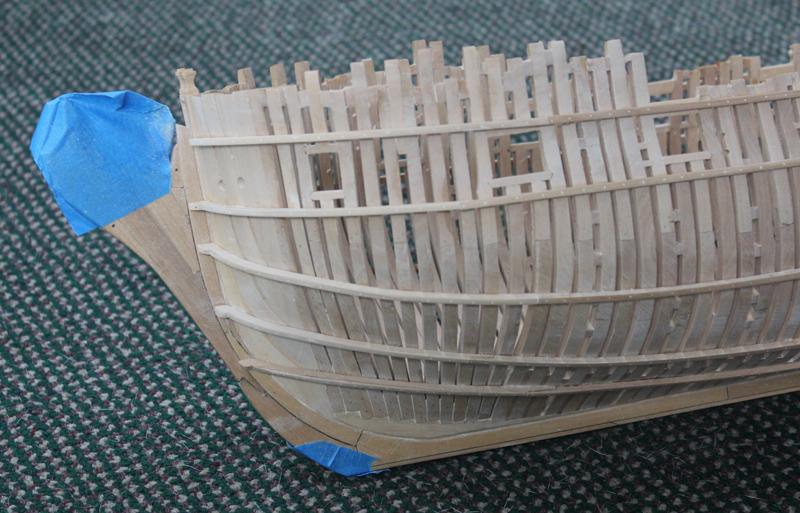
June 4, 2012. The gun port sills have been installed. My biggest problem was keeping the sills level across the ship. My solution was to take the glass bubble out of a level and place that directly on the sill.
Gun ports installed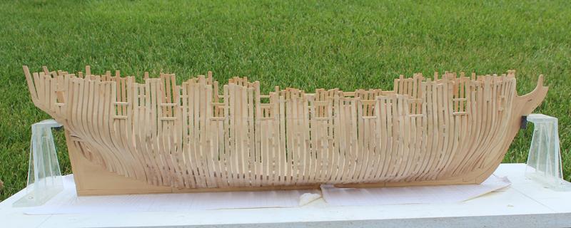
Author: Dan Vad. I’d leave the fixed blocks until later (like after you finish framing the upper deck). I don’t know how many times I managed to hit them when I was sanding parts of the deck. They don’t stick out much but just enough to be a nuisance. Danny.
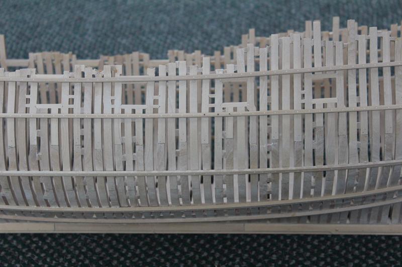
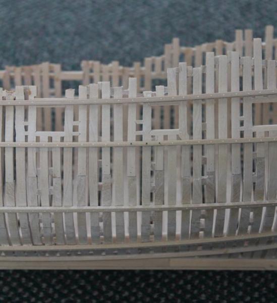
June 10, 2012. I have completed all of the sweep ports and will begin fairing next. The top timbers have been reinstalled above the gunports except in the waist where the top of the upper sill is immediately below the rail. The two close-up photos
show the inboard and outboard surfaces. It amazes me how much detail is picked up in the pictures. When I look at the model (even with Optivisors) I feel good about the appearance. But looking at the pictures it appears like the work has been done by a six year old. Sanding should take care of that!Sweeps Installed

Author: dvm27. When you get down to your final sanding grit, paint a dab of white glue into any gaps where the sills are, then sand. Those gaps will virtually disappear. Greg.
June 10, 2012. A little 60 grit has helped quite a bit. This photo is from the same part of the ship as the last photo. I only broke out two cant frames and had to reglue several of the topline spacers.Sweeps Sanded
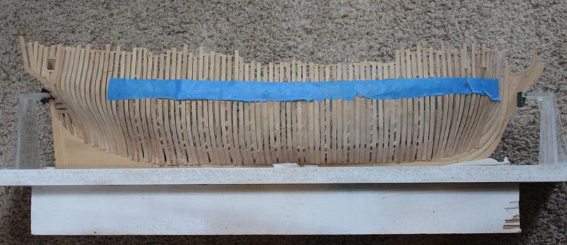
June 25, 2012. The last few weeks have been taken up with sanding and sanding and more…sanding. I took Danny’s advice and glued a temporary batten to the exterior of the hull for increased stability. I made no attempt to bend this around the bow. I used a rather stiff plank (1 x 6 mm) which I placed at the level of the gun port sills and removed several of the spacers at the top timbers. They will be replaced prior to removing the batten. You can see this on one of the photos.
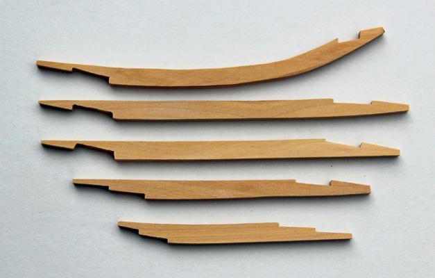
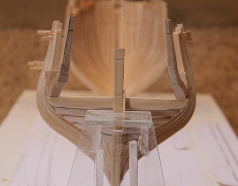
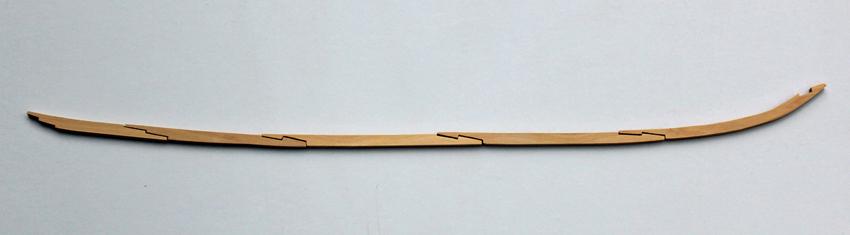
Although I am not finished with the internal sanding, I decided to fabricate the keelson. This is made up of five pieces connected with hook scarfs. The fore scarf will mate with the stemson. The aft deadwood is different on Atalanta than on the Mylar. I found it easiest to use a contour gauge to make a template of the shape. I then transferred this shape onto adhesive paper, leaving a generous amount superiorly, which was easily removed later. I still need to knock down the edges and notch one of the pieces for a crutch. The photo shows the pieces separated from each other to highlight the scarfs. The keelson is simply laid in place in the third photo.
Oh well, back to sanding.Keelson
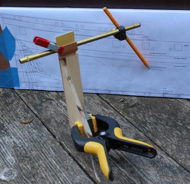
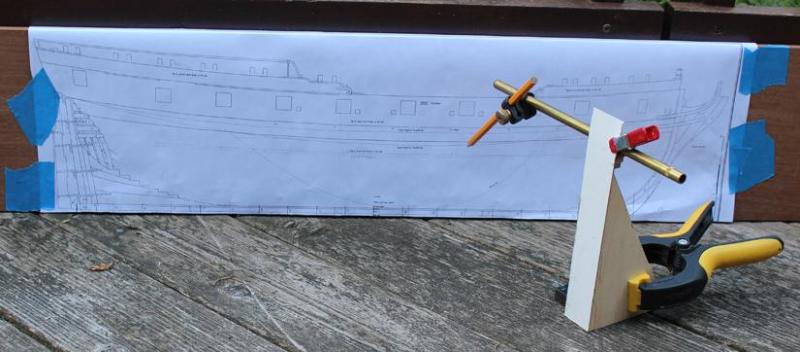
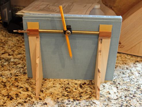
July 2, 2012. I have installed the stemson. If there is a contest for the biggest pain-in-the-you-know-where piece, the stemson is right up there. Between the hook scarf, the anterior shape as it meets the stem and the recesses for the deck clamp and breast hooks… Speaking of which, the clamp anterior to the fore mast is in a slightly different location than on the Mylar. This clamp straddles the scarf joint between the firth keelson piece and the stemson. The keelson is 12” but tapers to 9” as it fays with the stemson, which is also 9”. Bolts and trunnels are next.I made an interior height gauge to obtain the correct elevations for the stemson recessed. This will never win any beauty contests but it works well and did not require any metal work or “big boy toys”. I cannibalized parts from my exterior elevation gauge and framing jig to make it.
Stemson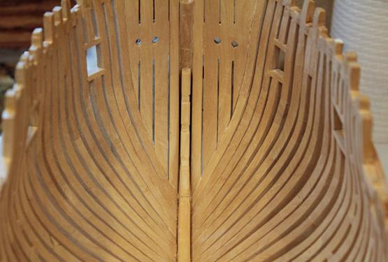

Inside Measurement Jig
- PeteB, archjofo, Elmer Cornish and 2 others
-
5
-
April 13, 2012. I wanted to get the topsides faired externally to make sure none of the frames needed to be reglued (or remade!). With the spacers glued in between the toptimbers, the hull feels reasonably stable at this point to safely remove it from the building board. The final fairing of the lower external hull will wait until the fillers are in place. I have decided to install the gunport and sweep sills after fairing. I think this will increase my accuracy in determining the sill heights.
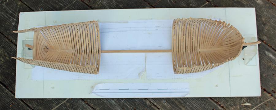
May 11, 2012. I have drawn out about 20’ of bamboo to start the treenailing. I equate this task to putting in rat lines. I started to mark out the gun ports and discovered that for two of the cast frames (nos. 4 and 8) I had placed the bend of the cast to superior. These frames were removed and new top timbers were made. Progress continues on the filling pieces I have found that the easiest way to tackle them is to make strips of wood the thickness of the largest space between the frames. Then, using a thickness sander, the strips are gradually thinned down and offered to the spaces between the frames. The filling pieces add significantly to the structural integrity of the hull at this point.May 23, 2012. I have finished the filling pieces. I used Swiss pear to give a little contrast with the boxwood. In contrast to the pear that Danny is using in his Vulture build, this is less pink. Maybe it is the age of the wood; these billets are 25 years old. I initially installed port and starboard pieces simultaneously to prevent warping of the keel (thank you Danny for that lesson!) but once everything felt solid, I removed the hull from the building board and added them where ever they would fit. I deliberately left out the filling pieces on the frames that had spacers for aesthetics and to allow a little light to enter the lower hull. The pictures show them roughly faired in. They will be finished after the gunports are completed.
Filling Pieces
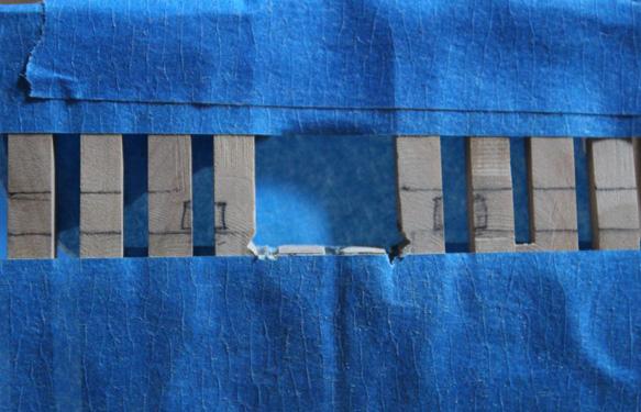
I have begun cutting out the gun ports. I read a lot of approaches and came up with the following. The top edges of the lower sills were marked out on the hull by taking measurements from the Atalanta draughts. These heights are a little different than shown on the Mylar. Next, I took a strip of blue masking tape (the kind that does not leave a residue) and ran a fair line along the hull connecting the marks. Any adjustments to the sill heights were made now. The lower edge of the upper sill was drawn in next, followed by the lower edge of the lower sill, sweep port and fixed block locations.
Now came the moment of truth! I started in the mid-ships area so that I would not initially have to worry about replacing the top timbers. The upper sill extends to the top rail. I cut the timbers about 2 mm above the final location of the sill seat on both sides. Then, a batten was placed through the opening s to confirm that the sill was level athwartship. The ports follow the angle of the deck so the fore end of the sill is slightly higher than the aft. The lower masking tape helps to prevent inadvertent damage to the frames and the upper tape adds a little extra stability. Although difficult to see, in the last picture the batten in running between the ports.
Masking for Gunports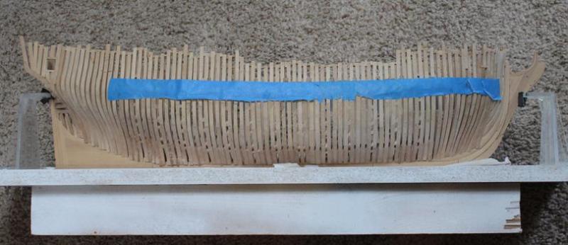
Masking Removed
Gun and Sweep Ports Marked
Lower Sill
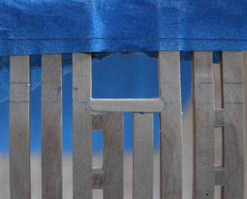
The next order of business is to cut the birdsmouth mortise. After marking it out I used an Exacto keyhole saw to mark the deepest part of the mortise. This helped me keep the Swiss files that were used to complete the mortise from wandering initially. This is easier than cutting out the cant port mortises since these are at 90 degrees to the keel. The sill was then slid into place. In the second picture, the space between the sill and frame spacer needs to be cleaned out. The upper sills have a triangular mortise. Because this is amidships, all that was required was to cut down to the top of the mortise and file the angle.Birdsmouth
Completed Gunport
- Jeronimo, Elmer Cornish, Wishmaster and 3 others
-
6
-
Hey, Geoff! You changed your avatar. Optivisors on the dog... Does it help him see better when he/she sleeps?
-
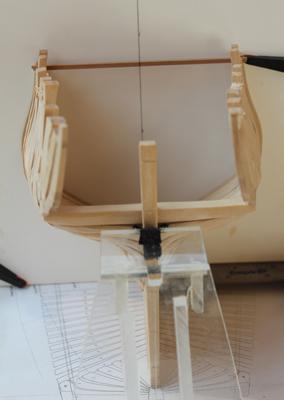
Love the display base.
-
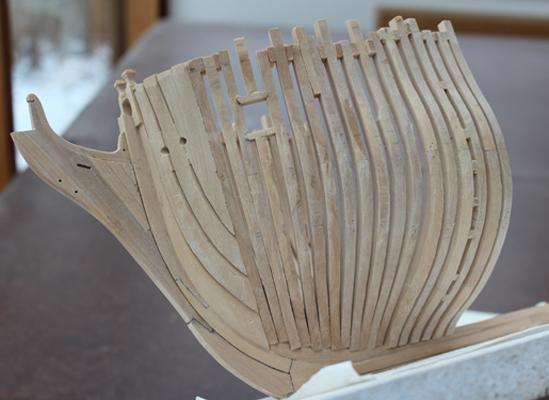
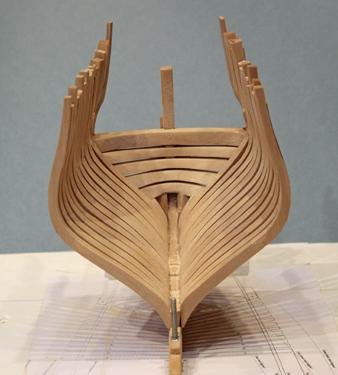
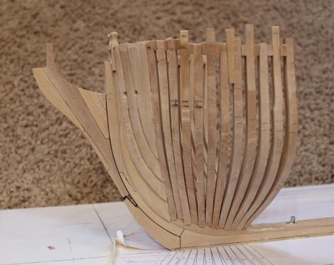
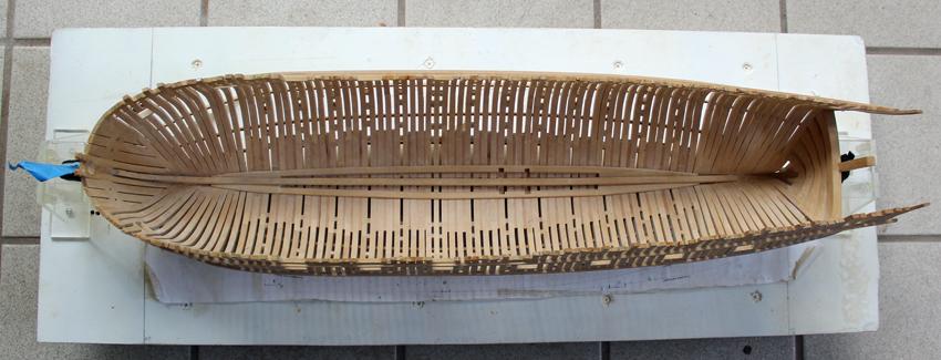
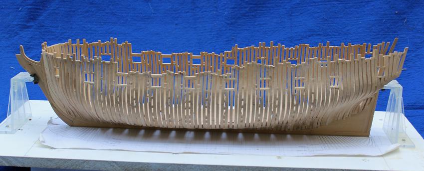
March 19, 2012. Frames 9-14 and F-L are mounted and the interior faired. No exterior fairing has been done. I have decided not to cut in the gunports and sweeps until all of the frames are in place. (Next time I think I will pin the frames in place that require sill mortices, mark everything once all the frames have been erected, remove the pinned frames to cut the mortices off the and then permanently remount the frames.)
Eleven Frames Completed

- PeteB, Elmer Cornish, Wishmaster and 1 other
-
4
-
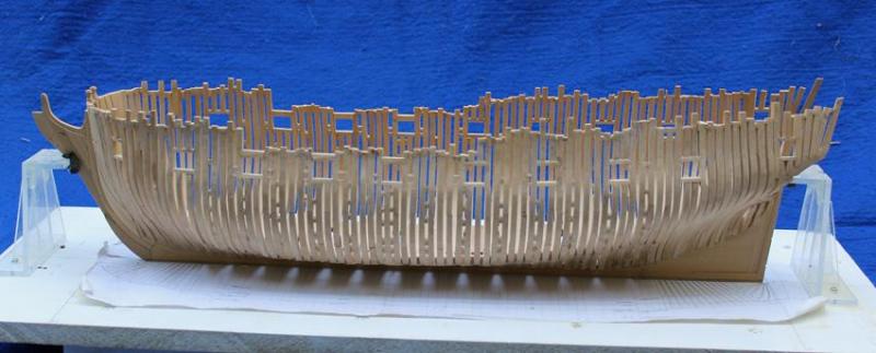
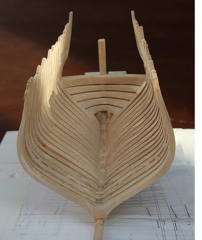
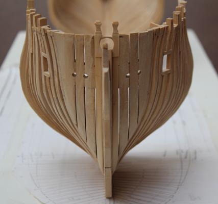
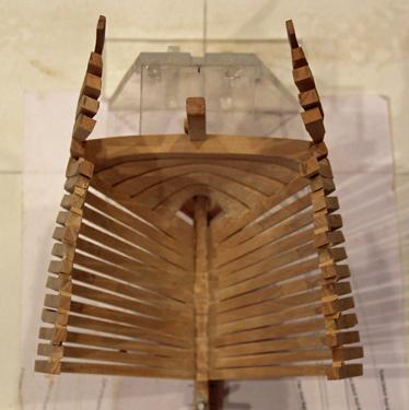
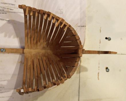
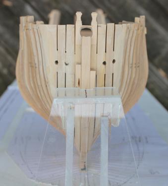
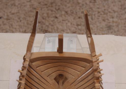
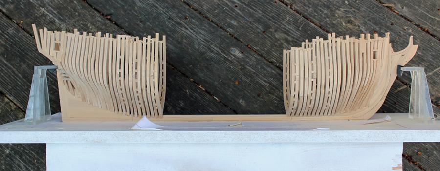
Feb, 27, 2012. The first few aft full frames are installed and I am in the process of fairing the inside of the hull. For anyone fairing a hull I would recommend taking pictures of the progress and examining them for any irregularities. There are things the lens “sees” that the eye does not.
Aft Faring
Author: dvm27. When fairing, I rely more on feel than anything. Running an open hand across the hull tells me when it’s as smooth as a sheet of paper. Wait until all the frames are in before final fairing. Greg.
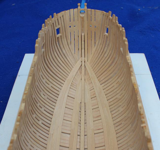
Feb 29, 2012. Greg, I found it necessary to do preliminary exterior fairing of the upperworks to get a feel for the true shape of the hull. The lower hull will not be touched until all the frames are mounted. I have mounted the first three fore frame pairs. Once mounted, I sighted down the keel to make certain there was no twist in the hull. This is most easily done with the camera. The next two pictures show the interior and exterior of the bow before any fairing.
Stern View
Interior and exterior bow
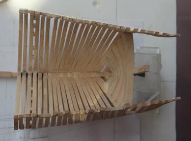
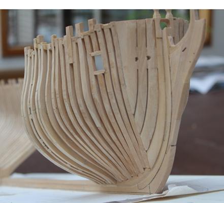
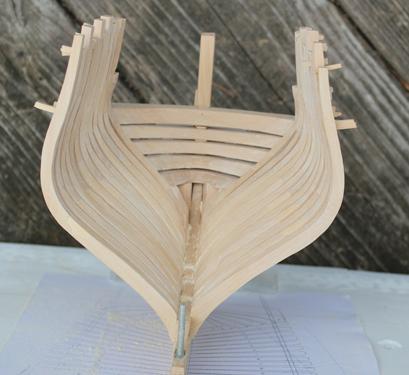
March 5, 2012. I have started to fair the port side. A moderate amount of fairing of the exterior was done on the lower part of the hull just to make sure the frames were correct. It is amazing the amount of excess wood removed. The inner fairing was done with a sanding disc on my Dremel outfitted with a right angle drive attachment followed by hand sanding. The pictures show the partially faired port side and the unfaired starboard side for comparison.
Interior and exterior bow partially faired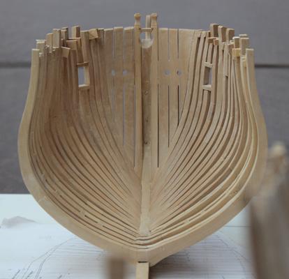
Port and Starboard Bow
-
Having built this kit, I am enjoying reading the log again. I bought the pear kit and only minimally planked it (also in pear), using apple for the wales. Keep up the beautiful work.
-
Why do you think I switched?
-
-
Thank you, John, for looking in. Greg, I assumed when Remco wrote that he was referring to the final sanding of the fore and aft faces of the frames, not the inner and outer faces of the frames.
It is interesting (and fun) to see the changes in building preferences and techniques in oneself over time. I initially hated chocks and now see that they actually simplify the joining of two complex pieces of wood. Before starting Atalanta I did not even own a chisel (unless the hand-me-down from my father-in-law that I use to pry open paint cans counts). Now I don't even start a building session without having one out on the table. I've transitioned from being a CA-girl to almost exclusively using carpenter's glue. I'm sure we can all come up with a similar list.
-
Dec. 10, 2011. I have added the extension piece on top of the head of the knee. This also tapers anteriorly. Now that the counter timber and filling pieces are in place and partially faired, I have added the sills for the counter and bridal ports. This was a real pain to do with all of the frames in the way. I am glad that I waited until now because at this point I know the height and angle of the sills are correct. The lower sills are cut with a bird’s mouth and the upper sills are cut with a wedge shape. In the pictures it appears that the lower counter sill is tilted starboard but this is just shadowing. I think that for the full frames I will add the cuts for the sills as I install the frames.
Extension Piece
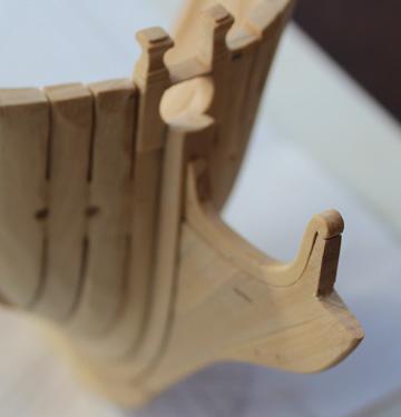
Bridal and Counter Ports
I am finding it rather difficult to make the beveled chocks for the frames I know a lot of builders use a mill but right now that is on my someday list. Until then, only 53 more frames to go!
Author: druxey. With a little practice and a very sharp chisel, plus really meticulous mark-out, making and fitting chocks will happen more rapidly once you get used to the technique. It is extremely difficult to get a flat faying surface using files. The surface will tend to round over as you file it.
Author: Dan Vad. Instead of using a file to finesse my chocks, I use a flat sanding board. I run the angled faces of the chocks one side at a time on the paper by dragging them toward me. It takes very little time to get the “feel” for the angles and how much pressure to exert on the leading or trailing edge. Leave plenty of width when rough-cutting the chocks in case you sand a little too much off one of the angles and need to sand a bit more off the other face to compensate – the inboard face will be faired with frames in any case.
Jan. 8, 2012. The frames are going a little quicker than anticipated. Eighteen down and a whole bunch to go! I decided to put chocks in all the frames. It actually is easier than plain scarf joints because of the reasons Greg stated a last month.
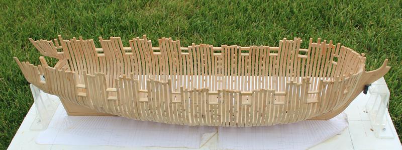
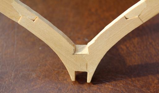
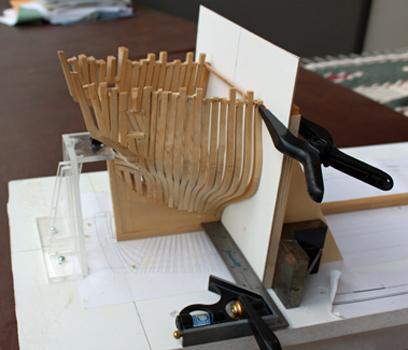
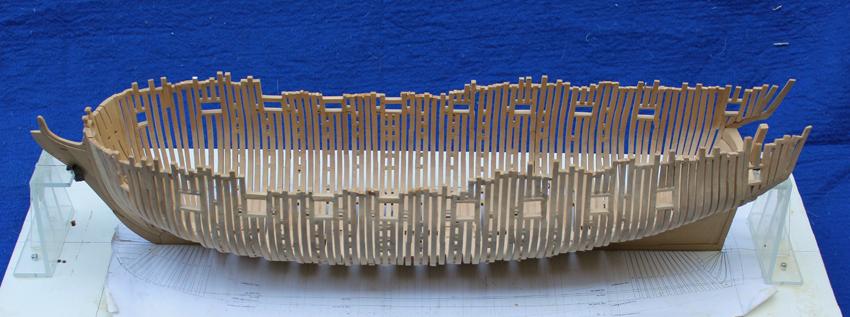
Feb. 17, 2012. I have finally finished all of the full frames (except for the cast toptimbers). By finished, I mean that they are all assembled and sanded to the outside line on the frame template. I have left the templates attached to the frames until each one is ready to mount to facilitate identifying them. As I prepare to mount them I will add the cross piece, do the final sanding of the fore and aft faces and put in the trunnels. The cross piece will be marked in the midline to help alignment. The first frame mounted is 14A (aft). The heels must be trimmed to match the shape of the bearding line and a wedge-shaped piece is removed from the floor to match the top of the deadwood after fairing.
Completed Frames
Full Frame
Heel
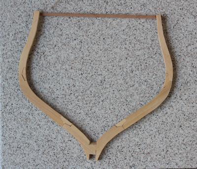
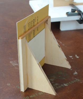
I made a jig to help ensure that the frames are square and plumb. I marked the midline and slotted the jig to fit over the keel. I chose to make mine from heavy cardstock with wood supports. I added a wood cross-brace and glued another piece of card on to the back to prevent warping.
Framing Jig
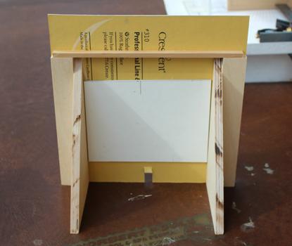
I have drawn lines on the building board to represent the fore face of frames 14A and 14F. As I add more frames I will continue to add these lines. Everything is measured from dead flat. The jig is then brought up to that like and squared true to the building board with machinist squares and contractor squares (at least that’s what they call them at Home Depot). The frame is then seated and glued in place. After the glue has set I will add spacer blocks at the top timbers. When using the jig, remember the timber thickness decreases with each successive futtock and one face of the frame is flat but the other has a stair-step. Frame 14A’s flat face is aft and the stair-step is fore. Therefore the framing jig only touches the floor futtocks. On frame 14F the flat face is fore and to the jig will be in contact with the entire frame.
Building Board Lines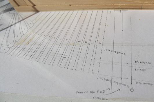
Jig in Use
- giampieroricci, Zarkon, Jeronimo and 5 others
-
8
-
Author: Dan Vad I started out doing that (chocking) to both sides before I realized that the port side wasn’t going to be seen anyway (planked over). I then used scarf joints instead of chocks for that side – MUCH quicker, neater and easier. Greg used ONLY scarf joints on his Pegasus – at the end of the day the chocks will be virtually invisible if you plan on adding any decks, etc.
Author: remcohe. All the frames on my build have scarf joints. I made scores with a scalpel to simulate the chocks. But the fairing made them disappear… I guess I don’t miss them on the inside, maybe I’ll add them again on the outside if I feel it looks better. RemcoDecember 5, 2011. I actually completed my first full frame. I decided to roughly sand down the counter filling timbers. This was done with the drum sander on the Dremel. Of course, as I was doing this the entire starboard assembly came off in my hand. The good news was that I had an easier time taking off the excess wood off the model and it also gave me better access to the port side. Except for installing the sills for the ports, Chapter 2 is now completed!
Counter Timbers
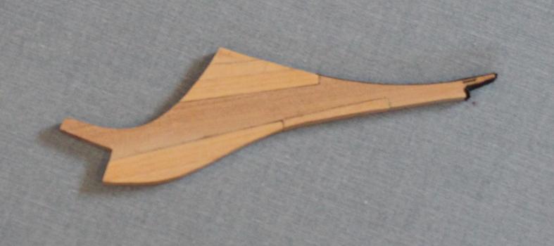
I had previously made up the knee of the head. I drilled the bobstay holes and the gammoning hole and cleaned them up with Swiss files. The lacing piece abuts the stem below water and this joint has a flannel lining. The more superior joints are above water and have no flannel. The lacing piece had to be trimmed the thickness of the flannel so that the assembly would lie flush against the stem. The knee of the head tapers from top to bottom and fore to aft. The narrowest part is scale 4” wide and at the stem it is scale 10” wide. I used pencil to highlight the edges of the various pieces.
Bow
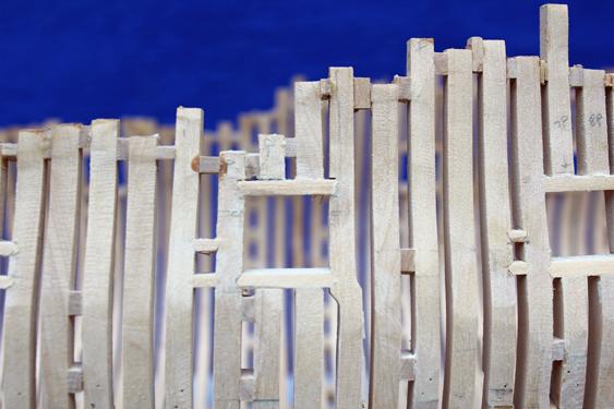
Dec. 5, 2011. On to the full frames! Each of the timbers is a narrower width as you go from keel to toptimber. The lowest timber (the floor) is 10”, the next futtock is 9.5” and the toptimber is 9”. That translates into real measurements of 0.108”, 0.098” and 0.088”. It does not sound like much but it is a noticeable difference, as can be seen in the photos. I have decided to put the flat part of the frame aft and the stairstep fore unless I can see an offset on the plans. The framing plan (Disposition Plan) is actually for Cygnet, one of the other Swan sloops.
First Full Frame
Author: Dan Vad. One thing I would have done with the benefit of my 20/20 hindsight is to fit the fillings at the same time as each square frame. Cutting them (to the shape of the larger one in a pair) would be easier, they can be faired along with the frames saving double work, they’ll strengthen the whole framework immensely and they will space the bottoms of the frames and avoid the problem I had with the keel (twisting). Be aware that not all the spacings at the bottoms of the frames are the same – there’s quite a bit of variation which can be taken from the Disposition plan. Gluing the filling to the frame to be fitted and finessing it to thickness before gluing the frame in would be the way to go.
Author: druxey. The only caution to take if fitting the fillers as you go is that there should be absolutely no ‘creep’ or cumulative error, which would result in frames not sitting on station.
Author: Dan Vad. Do what Greg and I did – measure EVERY frame position from the dead-flat to the squaring jig position as you get ready to fit it. Mark it on the keel for reference to be double sure everything is lined up.
Author: remcohe. I would definitely put the fillers in while framing and not afterwards as I did. Remco.Author: AnobiumPunctatum. I would build all full frames first, before gluing them on the rising wood. I think it’s easier to correct the cumulative errors.
Dec. 5, 2011. I plan on making frames until I cannot stand it anymore before permanently mounting them. I have not decided whether I like the aesthetics of the fillers but at the rate I build I will not have to worry much about that problem for a few months. Unlike a lot of you more dedicated builders, if I get eight hours a week to build I am happy.Author: dvm27. I place the steps on the futtocks on the outside of each bend. This way, the spacers between the pair of frames are equidistant from bottom to top. A small concession to accuracy perhaps but it guarantees that each frame in the pair (bend) is parallel when raised. Concerning chocks vs. scarphed joints I actually find it easier to use chocks. In a chocked joint you need only to mate one face of each futtock to the other over the plan. After drying, the chock opening is traced over a bland and cut and fitted. Quick work with a disk sander. In a scarphed joint you need to mate the three faces of each futtock. It’s a lot fussier work. Of course, some of the toptimbers are designated with scarph joints on the framing plan so watch for these. Greg
- PeteB, Elmer Cornish and Jeronimo
-
3
-
Nov. 15, 2011. I had time yesterday to start the fore external and aft internal fairing. It is daunting to remove all that wood from the hawser timbers and fore cants.
Beginning the Fore and Aft Fairing
Author: dvm27. When fairing the hull I use a pencil to draw lines across the hull from top to bottom. As you begin to fair the marks start to disappear. This means the high spots are being sanded down towards the lower spots (which still have the pencil marks). The pencil marks are reapplied every so often. Once all the pencil marks have disappeared the hull is fair. Sweep your hand gently across the hull from time to time and you will appreciate the fairing progress. David Antscherl taught me this method and it has worked quite nicely. Greg.
Nov. 21, 2011. I have started working on the counter timbers and the knee of the head simultaneously. There is a lot of fitting and temporary tacking of pieces, so while the aft was drying I worked on the fore, etc.
I have the angle for the counter timbers set and the timbers are temporarily pinned in place. I have also started the external curvature of these timbers. The next step will be to carve out the excess internal wood and permanently install them. I will not finish the exterior profile until I start the exterior fairing. The mark on the aft side is the top of timber line. Atalanta’s top of timber line is 4” shorter but I went with the prototype instead. The timber’s angle is the key; the height can be shortened later.Counter Timbers
The shape of the bow timbers had to be redrawn from David’s plans. The stem of Atalanta has a slightly different shape from the plan, as does the anterior edge of the knee of the head. The cheeks are positioned 6” lower and the curve of the upper part of the lacing and extension is also a little different. All of the joints below water have black paper (felt) and the upper joints have pencil on the edges to make the joint more apparent. I need to sand the knee to its final shape and drill several holes before mounting.
There are always items that seem easy but in reality are not. The filler timbers between the aft cants and the counter timbers are one example. I spent a lot of time measuring and remeasuring the location of the side lights. Even though the height of the top timbers is different on Atalanta than on the prototype, the height of the side light is unchanged. There are six timbers on each side. Two of the timbers form the vertical sides of the side lights. There is a short timber under the sill. The four aft timbers need to fill in the remaining space relatively evenly while, at the same time, gradually angling aft to approximate the angle of the counter timber. The fore timber has an unusual configuration. It is notched onto the first cant frame and has an aft taper superiorly and a fore taper inferiorly. I left these timbers very oversize because I did not know how it would all come together.
I have started cutting the first few full frame pieces. The frames will have chocks between the futtocks except as shown in the plans.
Counter Timbers
-
Chuck, I am the person who put the fillers in between the bulkheads. It makes all the difference in terms of strengthening the frame. I think a lot of builders (including myself) have snapped off that stempiece. The basswood is very soft. I left mine off the model until all the hul planking was completed.
-
Thank you for looking in, gentlemen. I have about a third finished. I am going to try to get the next third posted this weekend. It is just so difficult to sit typing and sorting pictures when I would rather be making sawdust.
-
Aldo, there are much better people to take advise from than myself and I have not looked at the partners on the upper deck but if you want to see how it looks on the lower deck go to the first page of my Atalanta (re)build. This shows the partner with an octagonal exterior. David discusses the round vs octagonal hole in Vol I. Also, why don't you look at Danny's Vulture so see how he handled it. His build log is in the process of being reposted.
-
Robbyn, as you start to kitbash you will probably end up purchasing most of the power tools along the way. The only things that I have bought specifically for scratch building are a scroll saw, a thickness sander and a spindle sander. The first is necessary, the second is useful and the third is a luxury. I also do most of my work on the kitchen table, storing everything in the garage or basement until needed. Enjoy.
-
And he still manages to get underfoot. I just make sure my hands are empty when he does.


HMS Atalanta 1775 by tlevine - FINISHED - 1:48 scale - from TFFM plans
in - Build logs for subjects built 1751 - 1800
Posted
Pat, I have tried to save the best of the comments from other authors. In addition to the info, it makes the log seem more alive. I will tell you, my typing has improved quite a bit with this little exercise!