

tlevine
-
Posts
1,942 -
Joined
-
Last visited
Content Type
Profiles
Forums
Gallery
Events
Posts posted by tlevine
-
-
These two pictures were originally entitled Starting Over and were taken right after the crash. Beam sets 6 and 7 have been installed. Both of these beams have hanging knees.
Starting Over
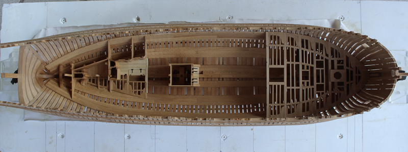

Beam sets 8 and 9 are reasonably simple…no hatches, no hanging knees, etc. What is deceptively hard is continuing a fair run of the carlings along the deck and ledges across the deck.
- fatih79, Jeronimo, Elmer Cornish and 4 others
-
 7
7
-
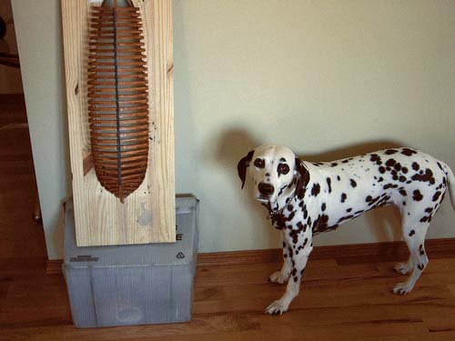
Thank you gentlemen. The dog may look innocent but... We have a saying: "All Sadie; all the time!". As soon as you hit a critical spot, she decides it is play time, squirrel chasing time, food time...you get the idea.
-
Thanks, Chuck.
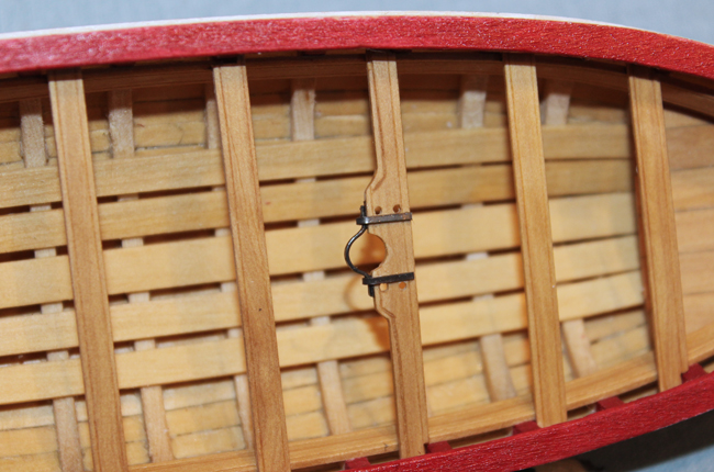
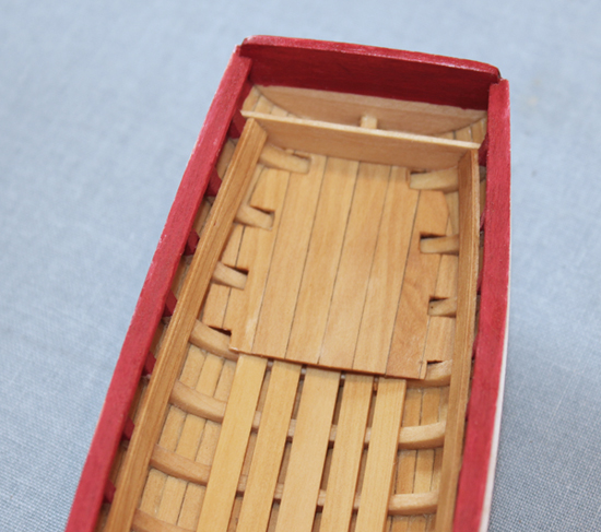
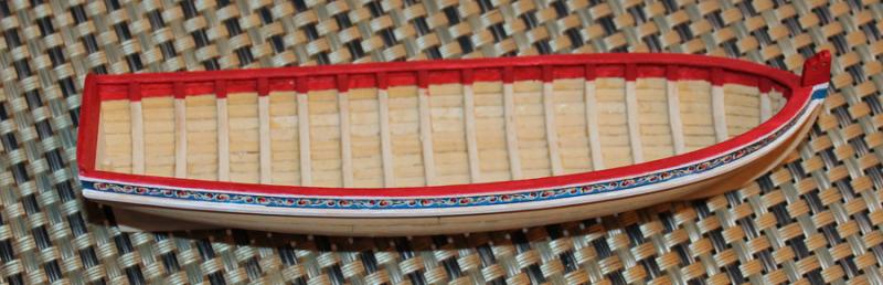
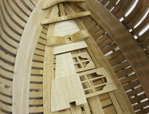
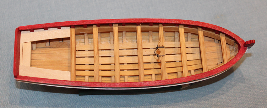
I scribed the edges of the thwarts to match the risers. The top edges were camphered but the bottom edges were left sharp. The thwart at bulkhead B is wider because of the mast. I took the scribing along the edge of the bump-out for the mast. The holes for the belaying pins were marked, scribed and drilled with a #64 bit. I will install them later. The mast bracket and support strips were made with the provided brass strip. I heated the strip in a gas flame to remove any laquer finish and temper the metal for easier bending. Once shaped, they took a bath in isopropanol and a dive into Birchwood Casey. The metal surfaces that would be glued were filed to remove the blackening and then installed with CA (one of the few times I have used it on this model). The thwarts were installed and then a coat of finish was applied.
The cockpit seats and trunk lid were made using the provided basswood pieces. Even though the thwarts and risers are boxwood, I decided to use the basswood as this area will be painted. In the pictures they are press fit in place. I have no paint with me this weekend so they will be permanently installed later.


-
Tom, Cabrapente, Dave, David and Michael, thanks for looking in. Sadie is very happy that she made an impression. She doesn't look that big next to Hannah.
- slagoon and Elmer Cornish
-
2
-
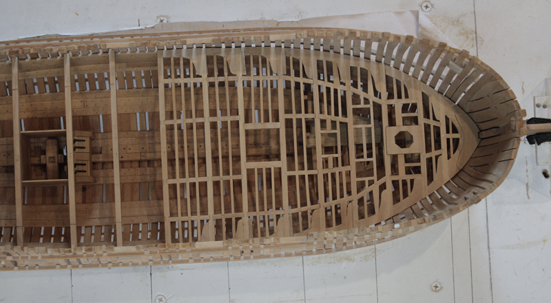
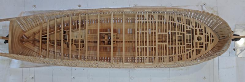
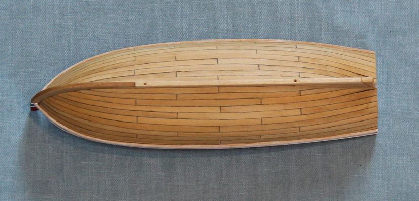
I have the radio on and was reminded that this time last year the temperature was in the low 80's. This year it is unreasonably cold. I was thrilled that it got above freezing for the first time in several weeks. I found a picture of the newly completed hull taken one year ago today and would like to compare it with my progress one year later. The good news is that I have not been distracted with gardening this year.

March 2012

March 2013

- fatih79, Elmer Cornish, PeteB and 4 others
-
7
-
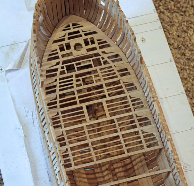
There are hanging knees on the fore side of beam 6. These are a pain to make because of the various thicknesses of the deck clamps and thick stuff. In addition there is the inward curve of the hull to account for. The hanging knee locks into the lodging knee and is bolted to the hull and the fore face of the beam.


- PeteB, fatih79, Elmer Cornish and 2 others
-
5
-
I guess admin got involved since I only see Bob's post once. Thank you both for your kind comments.
-
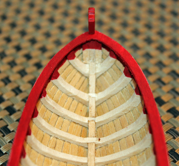
I went back and took a picture of the painted stem. Even though I painted over the dark blue/black at the bow, I left the dark color aft.
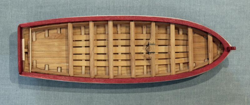
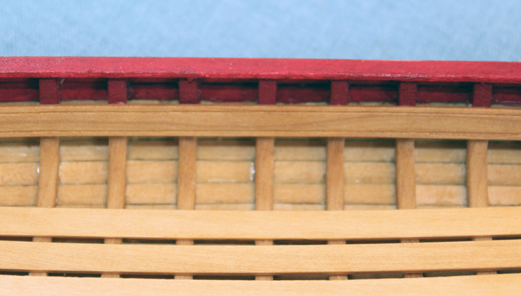
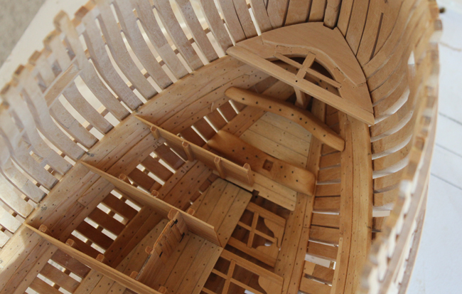
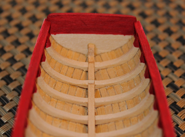
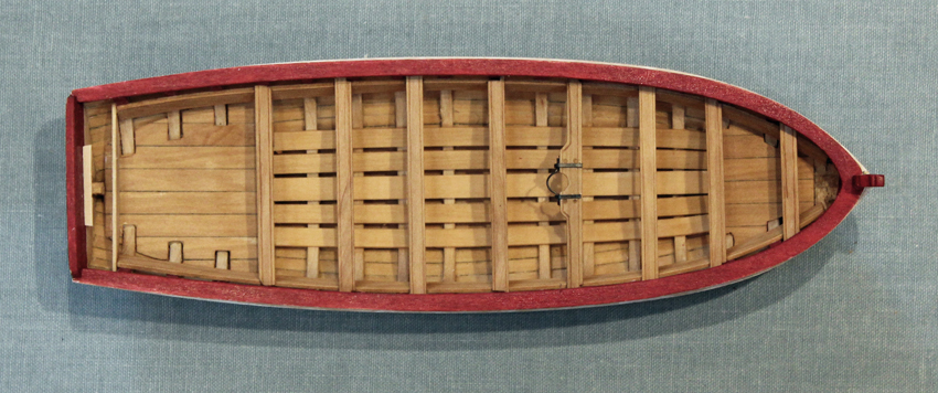
The floor boards were installed next. The central one is wider than the two outer ones. The instructions say to keep the distance between the floor boards the same. I was uncertain whether that meant constant along the length (and as a consequence tapering the floor board towards the bow) or symmetric so I tried both ways. Keeping the floor board a consistent width and gradually decreasing the distance between the boards looked better to me.
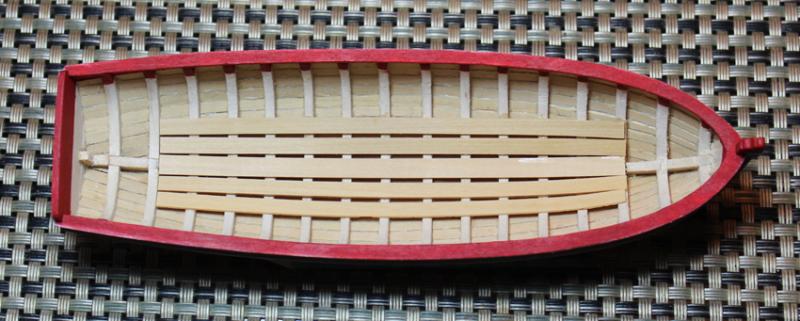
Once they were installed, I made templates for the fore and aft platforms. The photos show the aft platform stopping at bulkhead 7 but the plans show that it goes aft to the sternpost. I followed the plan. I used pencil on one edge of the planking to highlight the individual boards.
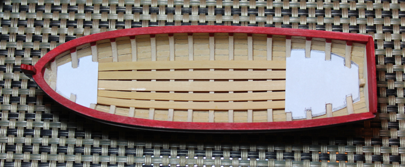
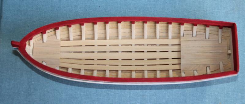
The riser strake was installed next. I scribed the top and bottom with an 11 blade using a straight-edge as a guidel It turned out that the correct distance from the rail was exactly where the paint-natural wood transition occurred. Another template was used to get the correct shape for the trunk, located aft of bulkhead 7. Once this was installed I applied a coat of Watco's Danish Wood Oil to the entire hull except for the painted rail. I am still planning on painting the hull below the water line white. I don't think I will have any problem with paint adhesion.

-
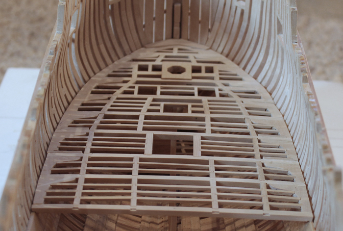
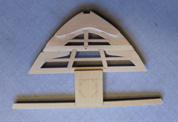
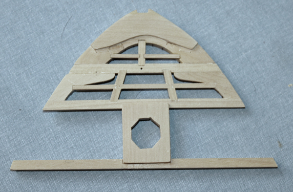
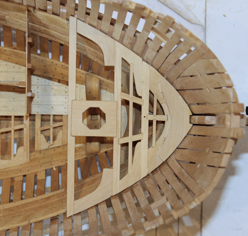
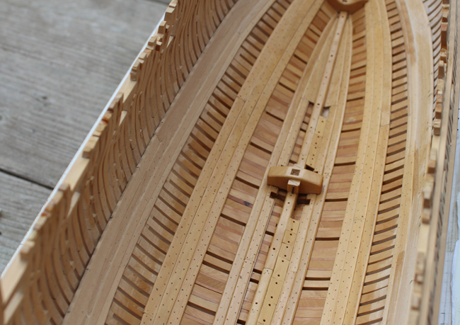
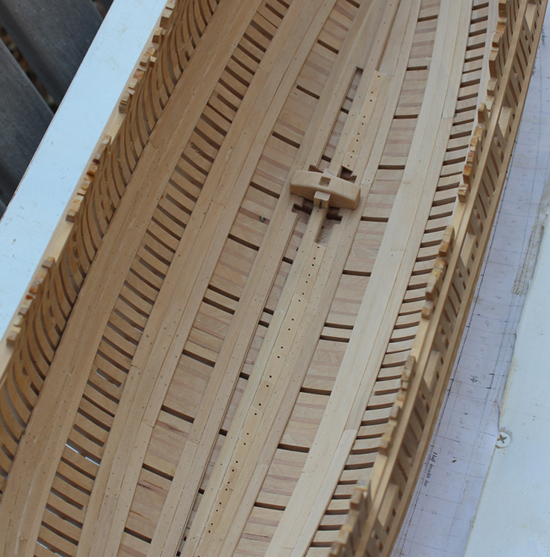
The foremast partner is an interesting piece of joinery and exemplifies why one should not glue things in place too soon. Although not seen in the pictures, there are two carlings under the plank between the second and third beams. These carlings are mortised under the beams and extend all the way across the beams. The partner is let into the beams by one inch. I made the opening by drawing it out and then drilling multiple holes just inside the outline. Using an Exacto, I connected the dots and cleaned up the octagon with a chisel and sanding sticks.
Foremast Partner

The lodging knees, carlings and ledges were made and glued-up off the model. I will call a beam and its associated lodging knees, carlings and ledges a beam set for simplicity. Finally the whole eking piece and beams 1-3 assembly was installed with the pillars.
Lower Beam 3 Lodging knees
Lower Beam 3 Carlings and Ledges


Lower Beam 3 Finished

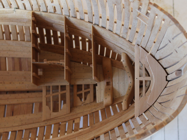
The next two beams were installed. Nothing gets glued together in one beam set until the next beam set has been made. As you can see, the angle of the inner carlings of beam set 5 is not symmetric. I mismarked the midline with the obvious result. I did not notice this until it was too late to correct the problem. Since one side of the deck will be planked over, the asymmetry will not be seen unless a fiberoptic scope is passed into the hold. After the trouble I had with beam 2, I have been very careful to make sure the beams are perpendicular to the keel.
Beam 5


- Jeronimo, Elmer Cornish, archjofo and 1 other
-
4
-
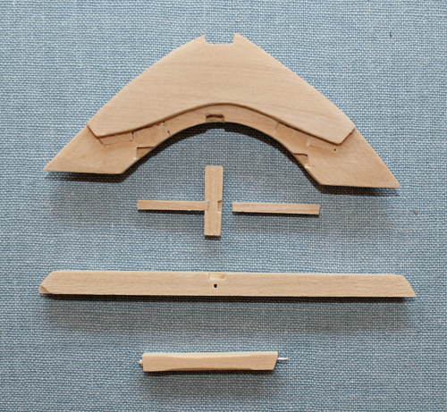
I was very proud of myself until… One of our members (I am sorry that I do not remember which one because you really did me a tremendous service by calling this to my attention) noticed that beam 2 was not perpendicular to the keel. The problem was determined to be the eking piece which was remade and the problem was solved. Happily, I had not glued anything in place on the deck clamp so nothing was damaged in the repair. While building the lower deck structure I have made it a rule not to permanently glue anything in place until I am at least one and preferably two beams down the line in case small adjustments need to be made. The picture on the left shows the problem. The starboard end of the second beam is half a frame width aft compared with the port side. The right hand photo is taken a little later in the build but shows that the beam is now perpendicular to the keel.
Remade Eking Piece

- archjofo, Jeronimo, Elmer Cornish and 2 others
-
5
-
Here are some more pictures for you Joe.
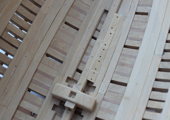
The lower deck hook/eking piece was made next. This is constructed from three pieces of wood hook scarfed together. Another difference from TFFM was found with this piece. The book shows the upper surface of the hook flat whereas the draughts show a rebate at the fore end of the hook. This would allow the deck planking to end on the hook rather than at the footwaling. The pictures show the sequence of construction of the eking piece, beam 1 and their associated carling, ledges and pillar. There is a deliberate gap at the lateral edge of the hook and beam because I am not installing any of the footwaling.
Lower Deck Hook


The second beam, with its knees, carlings and ledges was installed next.
Lower Deck Second Beam


- AnobiumPunctatum, PeteB, archjofo and 3 others
-
6
-
The fore platform bulkheads are less complicated than the aft ones. Everything is at a right angle in contrast to the odd corners aft. There is some difference in the door configuration between TFFM and the Atalanta draughts. Greg’s Pegasus also has this configuration (as seen in TFFM vol.3).
Fore Platform Bulkheads


This picture shows how the well lines up with the aft platform structures. The well will not be glued in place until the lower deck has been partially assembled. The color contrast shows where the finish has been applied.

-
I like your idea of a celebration, Pat. Mark, I am using propane and oxygen for the torch. Although not the most cost effective, I am using the little canisters from the hardware store because of their portability. The finish is Watco's Danish Wood Oil. My can of finish is five years old. I am suspicious that there has been a change in formulation recently, resulting in a shinier finish. Definitely try this product on some scrap before deciding to use it. Thanks for the encouragement, Christian.
-
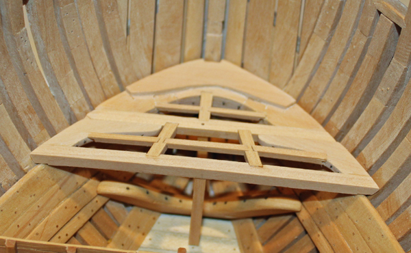
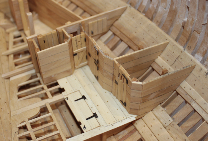
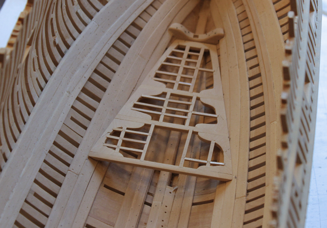
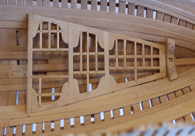
None of the beams are installed but I have decided to add the finished pillars as the bulkheads are fabricated. This is where I got in to trouble again. The fore bulkhead of the magazine rests on the platform beam and the pillar is fixed to it. Careful (after the fact) review of the plans shows that this pillar is not centered on the lower deck beam. It is shifted aft. The reason for this is that one could not open the passageway doors into the magazine if it was positioned directly under the center of the beam. Openings have been made for the door into the magazine, the light window and the scuttle into the bread room.
The mullions for the light room window were made by sawing halfway through the wood strips and then assembling them Lincoln Log style. The glazing is mica. The candle is typing paper rolled around a scrap of wood. The weathered appearance is purely accidental. My fingers were dirty when I made it.
Light Room Bulkhead

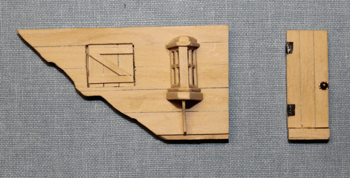

Fore Magazine Bulkhead


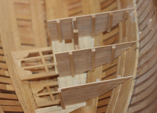
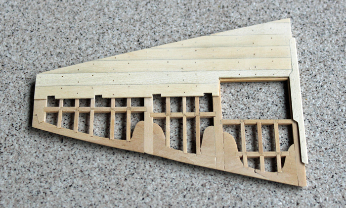
The remaining rooms on the port side of the platform have been made and installed. Since all of the wood planks for the bulkhead walls are the same dimension, I made up a stock “wall” made up of strips of wood glued together. The lengths of the bulkhead segments were then cut from that stock sheet.
Holes are drilled into the upper light room door for ventilation. The hinges on the steward and bread room doors are photo etch from Admiralty Model’s photo etch sheet for Swan Class vessels. This also includes pump assemblies, lanterns and other misc. parts.
Aft Platform Bulkheads
I have reached the end of the build log rescued by Dave (Midnight). This leaves me about two months to reconstruct de novo. At least I have the pictures...
-
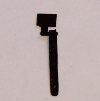
The hinge assemblies were blackened. I have used Blacken It for a long time but I have some Birchwood Casey’s on order for the next batch of metal work. Once they are installed and the finish applied to the wood, I will apply a coat of Floquil reflectance reducer to the hinges. This will even out the color and protect them from getting the gray bloom that plagues blackened fittings (at least mine). I am still deciding on what adhesive to use. I find epoxy too messy. I am considering contact cement. I used it to apply the copper plates on a Cutty Sark twenty years ago and it has shown no signs of failing.


Author: druxey. Silver solder and brass soup…been there and done that! On the other hand, I accidentally discovered a new technique. Heat the end of a wire or thin rod. The tip will melt and form a nice ball. Great for metal stanchions!
Author: Dan Vad. Epoxy doesn’t have to be messy to use on very small pieces. The trick is NOT to try to clean off any excess until it has at least ¾ set. Then trim it off with a sharp Xacto.
Author: remcohe. I used very small drops of thick CA to fix them.
Author: druxey. Excess epoxy can also be removed before it is set up by – yes, you’ve guessed it! – isopropanol. I use a Q-tip to do this.
Dec. 3, 2012. I did not like the effect from my blackening solution so I took the hinges back to almost bright metal by soaking them in Sparex pickling solution and reblackening them in Birchwood Casey Brass Blackener. Quite an improvement. I installed the hinges using contact cement. I put a tiny stripe of the cement on the door and on the hinge. I let it dry for 15 minutes and then installed them. No adhesive squeezing out. I deliberately made the hinge pins come from the same side. It seemed to me that it might be necessary for someone to remove the lid for access or repair and this would allow the door to be removed more easily.


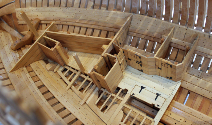
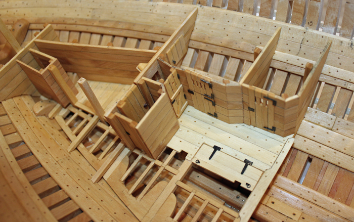
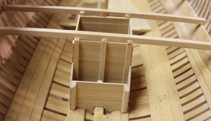
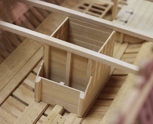
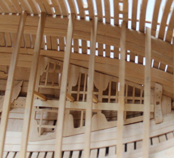
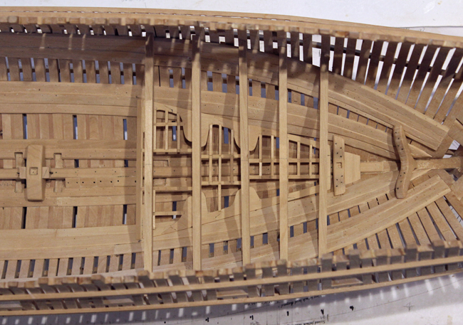
Dec. 3, 2012. There are several rooms built on to the aft and fore platforms. On the aft platform are the magazine and its maze of entry passages, the bread room, the steward’s room, the light room and other rooms on the starboard side of the ship which I will not be installing. Superficially, this seems easy. Build a bunch of walls, trim them to fit, put in a few fenestrations, pop in a few door and voila…instant room. Needless to say, this is not the case. One of the hardest parts of this for me was visualizing how everything went together. I then followed the platform plan, only to discover that the fore and aft positions of the bulkheads were slightly different from the body plan. “Slightly” loosely translates into just enough to make me start over.
I decided to start aft and work forward. The aft magazine bulkhead sits behind the mizzen mast step.
The aft bulkhead does not go all the way to the hull. There will be a bulkhead connecting the fore and aft magazine bulkheads and lateral to that is storage for the bread room. There is a box surrounding the mizzen mast, keeping it separate from the magazine. The magazine also has a removable false floor, called the palletting. These planks go athwart ship in contrast to the deck flooring. My first mistake was making the magazine area too short. The fore pallet beam had to be remade and a wider plank installed. Compare the 2nd and 4th pictures for before and after shots of the pallet beams and decking.


- archjofo, Jeronimo, Wishmaster and 3 others
-
6
-
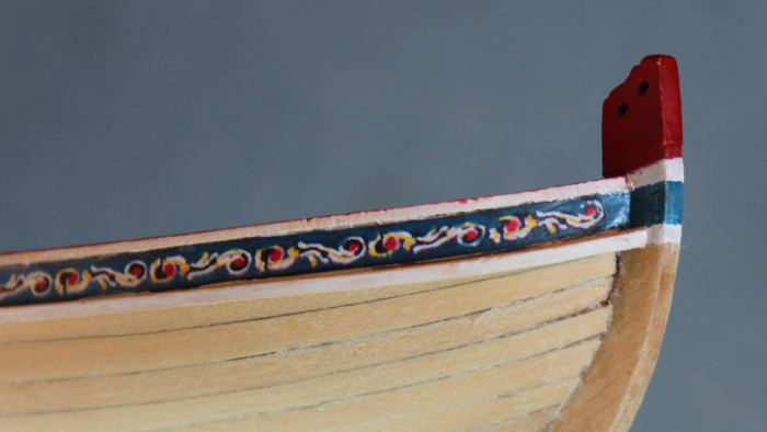
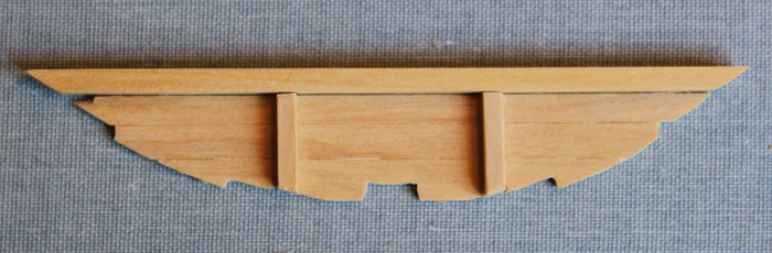
Time again to take a short break from Atalanta (and resurrecting build logs). I used the second to smallest freize downloaded from MSW for the transom. The kit supplied ones were too large. I used very dilute yellow glue to apply the freize and then painted over it with Testor reflectance reducer.
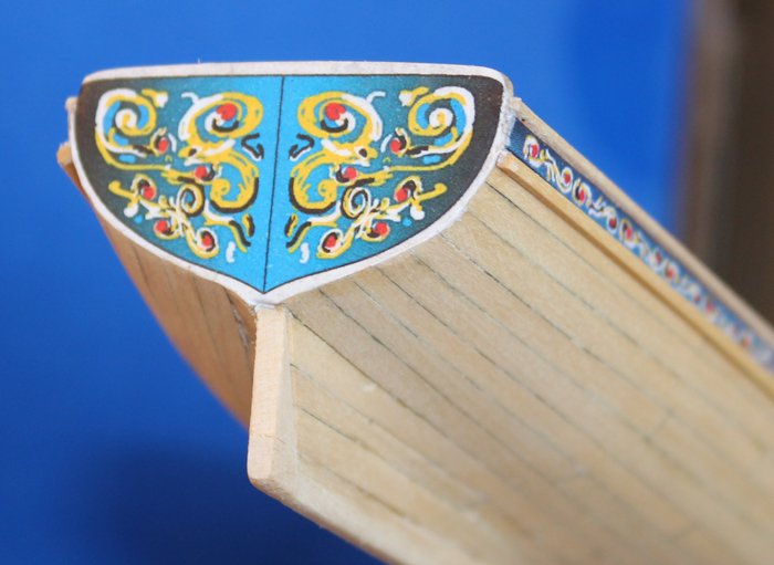
The rail, inner bulwarks, etc. were painted with Polly S Soo Line Red paint. The rub rail and edge of the top rail were painted with flat white enamel. The kit instructions suggest using black paint on the stem adjacent to the freize. I had some blue paint (Testors Blue Angel enamel) which matched the color of the freize and used that on the stem. I then feathered the paint onto the freize where the blue darkened to near-black. I will try to remember to take a picture of that and post it next time.
- archjofo, harvey1847 and Chuck
-
3
-
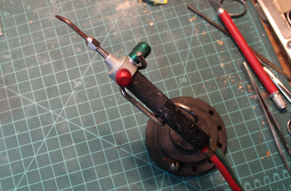
This is the web site for the torch. A lot of builders in my club use this same torch. http://www.littletorch.com/
-
Thanks, everybody. Sorry for the delay in responding. Between life and the site going down again...
Joe, that is a Smith torch. It is used in the jewelry trade. I got mine probably on EBay. It comes available with seven tips of various diameters. I use one of the medium tips. The smallest tips are difficult to stay lit with the gasses I use.
I will try to post more of the build log tonight. In real time, I have just finished the holes in the main mast partner for the pumps.
-
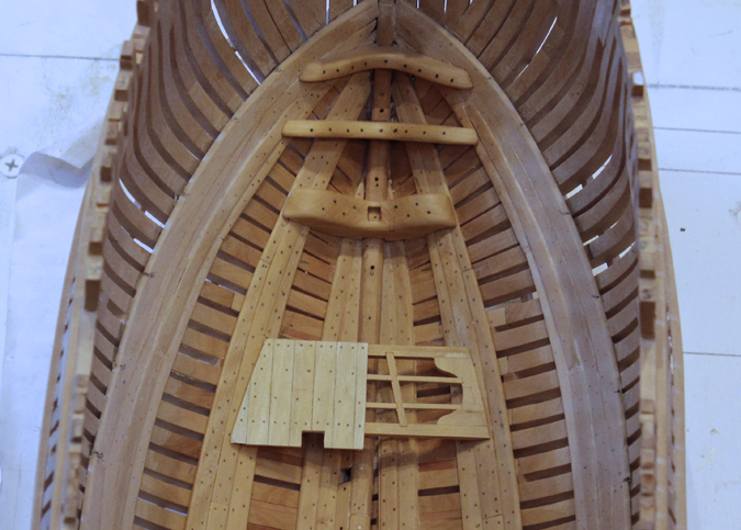
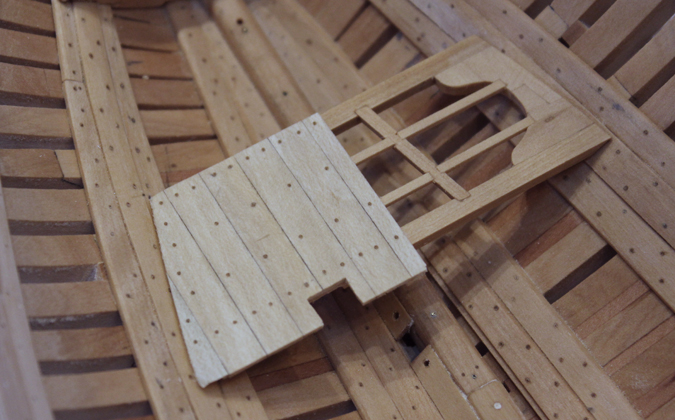
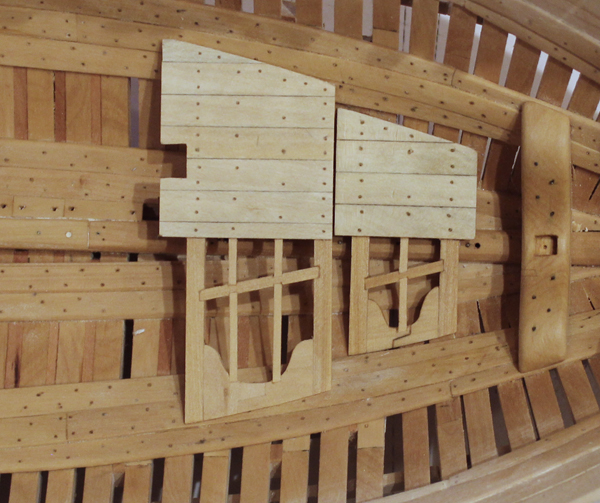
I decided to build the lower well/shot locker before the fore and aft platform bulkheads. This would give me more room to work on the well without damaging the bulkheads. The well will be permanently installed later. I build the lateral walls of the well first. Since these planks had cyphered edges, I did not highlight the plank edge with pencil. I then added the stanchions, cutting them long for later fitting with the lower deck beams. The athwartship walls were installed next. The lowest plank is wider and shaped to fit the hull configuration.
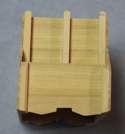


The next step was to exactly locate the well/locker fore and aft on the keelson. I had previously marked the locations of the lower deck beam stanchions on the keelson and inserted the tenon of the aft wall stanchion into this. I removed the limber boards on either side of the well and will remake them to fit later. Next, I took the lower deck beams and placed them adjacent to the athwartship walls, marking the correct height. The stanchions were cut down, keeping the mortise (for the most part) to insert into the underside of the beam.

Now it is time to add the finishing touches. The doors to the shot locker would not have been as air tight as the walls, so these plank edges were highlighted with pencil. I also left a slight gap on either side of the door to highlight the idea that these are two separate doors.

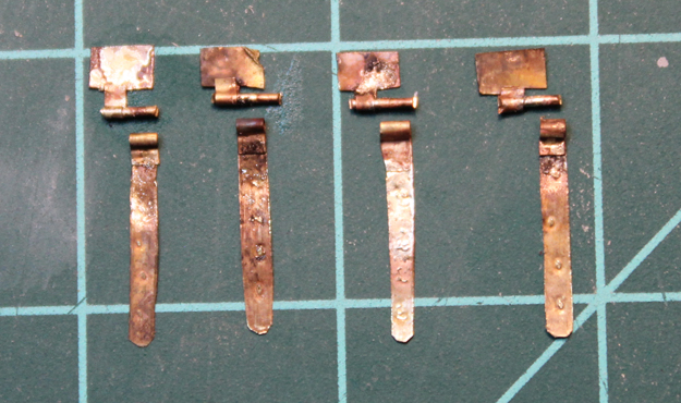
Nov. 27, 2012. I made the hinges for the shot locker. I started with shim brass (the second thinnest in a pack containing misc. thicknesses) and heat it in a gas flame to remove any lacquer that might have been applied at the factory. Next, a strap and an offset “T” piece for the hinge were cut. The hinge pin is a brass pin from Model Expo. I put pins in both pieces and formed a loop around the pin. The pin was left in place on the hinge plate and both pieces were silver soldered. I use a Smith Little Torch using propane and oxygen because it gives me a finer flame than a butane torch. With the thin brass this is important because there is a fine line between soldering the joint and creating a brass/silver soup. I attempted to dimple the strap for nail heads and was not very successful so I will simply call it “distressed metal.” With the naked eye you cannot see any detail of the surface of the metal.


- Wishmaster, Mcdood, Jeronimo and 3 others
-
6
-
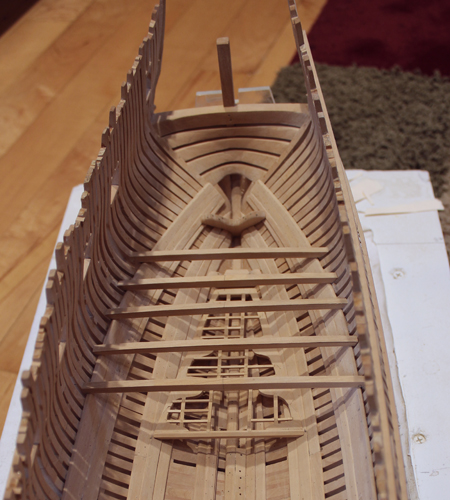
Nov 19, 2012. I am at the point of applying finish to the areas of the hull which will soon be unreachable. The first picture shows the finish applied only to the port side to illustrate the effect of the finish. The second picture shows the finish applied to both sides up to the top of the lower deck clamps.

The aft platform has been installed along with the fish room bulkheads. The door to the fish room is notched to accommodate the pillar from the lower deck beam to the keelson.
Aft Platform Installed

Nov 19, 2012. I have started the fore platforms. There are three of them, each at a different height. They are made in a similar manner to the aft platform. One must be careful to locate them relative to the various pillars. The most critical of the platforms to locate is the aft one because the riding bitts run through the aft end of the decking. The difference in the color between the two platforms is a result of the picture being taken a few minutes after I applied the finish on the middle platform and a few hours after it was applied on the aft.
Fore Platform


Nov. 26, 2012. The last two sections of the fore platform have been installed.
Fore Platforms Finished
-
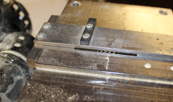
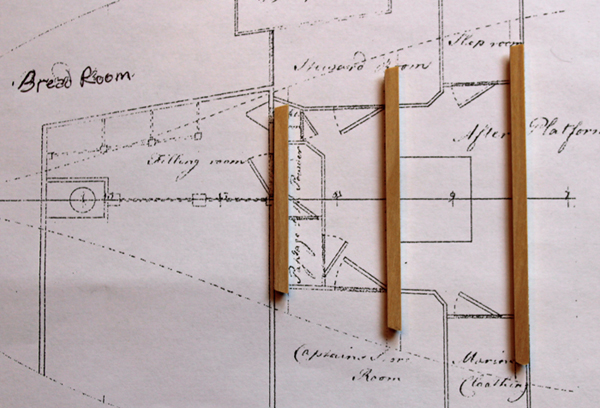
Nov. 10, 2012. The pillars between the deck beams and the keelson have been temporarily installed. Just as with the deck beams, I have left them rough until final installation so I do not have to address any damage from storing them. There is a mortise at the top and bottom of the pillar. I made the mortises with the Preac saw. By positioning the blade to that it barely clears the table I am able to get a square mortise which is perfectly positioned in the middle of the pillar. The top and bottom faces of the pillar are horizontal athwartship but not fore and aft because of the rise of the keelson and lower deck as one goes aft. The last two pillars extend to the upper deck beams. The pillars will be chamfered prior to final installation.
Pillar Blank


AFt Lower Deck Beams and Pillars

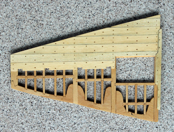
The deck planking is 1” x 12” holly. I realize there would be no caulking of this deck but I used a pencil on one side of the plank so that the individual planks would be apparent. I tried it without first and it looked like a sheet of plywood. Cut outs have been made in the first plank for the pillars. According to TFFM, dowels were used on beams and trunnels were used on ledges. They were the same size (3/4”). I used bamboo for the trunnels and holly for the dowels. Holly is no fun to pull through a draw plate!
I am at the point where parts of the model need to have a finish applied. I am using Watco’s Danish Wood Oil. As you can see, the holly dowels are almost invisible until the finish is applied. The color difference between the bamboo and holly is subtle.
Aft Lower Deck Beams and Pillars
Aft Platform Decked

- PeteB, Wishmaster, druxey and 4 others
-
7
-
Your pictures of splicing are fantastic. I have never seen a better explanation of the process.
-
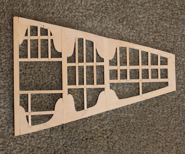
Oct. 8, 2012. The next project to tackle is the aft platform. On these smaller ships, there was no orlop deck so the fore and aft platforms served the function. The location of the platform beams were taken off the draught. The difference in length from the draught is a combination of probably removing too much wood during fairing and the thickness of the inner planking. There are two bulkhead walls which intersect the first two beams. These are the fore and aft fish room bulkheads. The planks are 2” x 9” and are cyphered or bevel-cut on the long edges. I made the planks 2” x 6” and eliminated the cypher as this will never be seen and I do not have a disc sander or a tilt table on my saw to get a consistent bevel.
There are two stanchions on the fore face of the fore bulkhead. These mortise into the limber plank and the fore platform beam. You can see the mortise and tenon for the platform beam. The limber plank connector will be a brass pin which I will insert when the platform is ready to install. I will be planking the port side and leaving the starboard exposed.
Aft Platform Bulkheads
Nov. 5, 2012. I have completed the framing for the aft platforms. The port side will be planked and so I have not installed all of the ledges. The mortises are all made with the diagonal cut technique rather than a step-mortise. I will try the other technique when I make the fore platforms. As I do not own a mill, the mortises are made with a razor saw and finished up with and 11 blade scalpel. The platform actually looks much better than the photos would suggest. Since I am not installing Footwaling, there is a gap between the lateral edge of the platform and the hull framing. As this platform will basically be invisible once the model is completed, I omitted the fasteners in the knees.
Aft Platform Frame
In order to complete the aft platform, the aft lower deck beams must be temporarily installed. There are pillars extending from the beams to the keel and these pass through the platform. There is a 3” roundup on the lower deck. Everyone has their own technique for shaping beams. My approach is to make a template of the roundup on thin balsa. I then draw this line onto an oversize beam blank. Using a spindle sander (a disc sander would be better but I don’t own one) I shape the top of the beam almost to the line and then finish it with sandpaper. Next, I fit the beam to the lower deck clamp. The beam is let 1” onto the clamp. Finally, I mark out the lower edge of the beam and repeat the process used on the top. The hardest part is getting a tight fit against the hull because of the compound curves. There is no footwaling so I should be leaving a 2” gap at the end of each beam. I did this and it looked sloppy. Therefore, I took builder’s license and extended the beams out to the hull timbers. After placing the beams on the clamps, I was thrilled to see that a straight-edge placed in the midline on top of the beams was flush with the beams. Final sanding and shaping fore and aft will wait until the beams are permanently installed.
Lower Deck Beams Aft
- Elmer Cornish, Remcohe, Jeronimo and 2 others
-
5
-
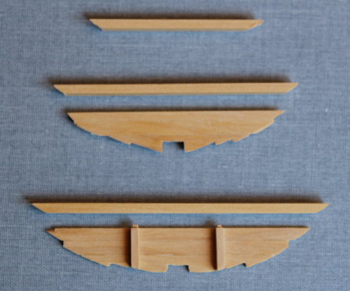
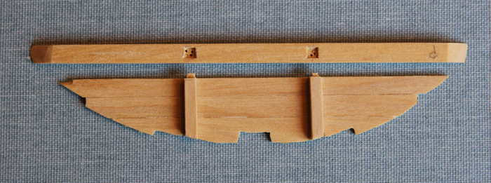
Sept. 30, 2012. I have come to the first project which requires a decision about how to build out the interior of the hull. I have decided to leave the starboard side open for viewing as much as possible and completely build out the port side (except for the Footwaling). The next items to install are the limber boards. These are supposed to be approx. 36” long except under the hatches (18-24”). I marked out the location in the bilge for the hatches, fore partition and well. I then divided these spaces evenly and came up with long boards of 32” and short boards of 20”. The second photo shows two long boards and three short ones.
Limber Boards
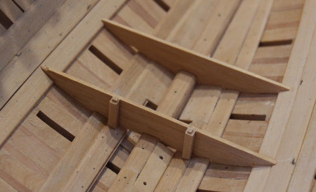
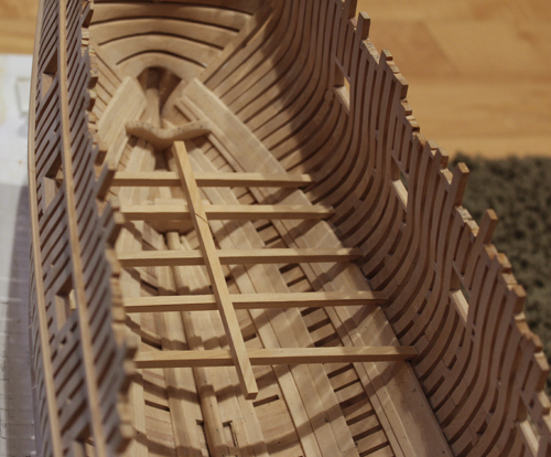
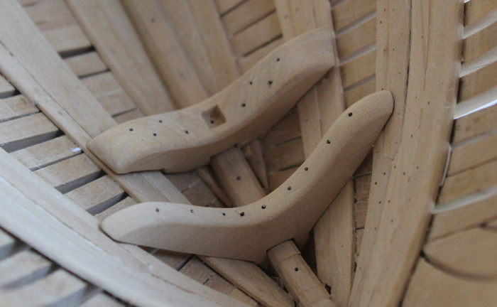
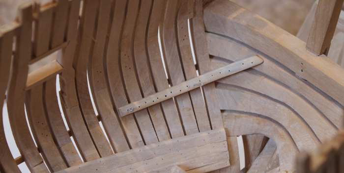
The aft crutch was next. It really does nook better in real life than the photo would suggest. I know there is a problem with the height of the top board of the aft deadwood but I could not figure out a way to rectify it at this point so I simply glued the crutch on to the top of the deadwood. The crutch and the breast hooks are perpendicular to the angle of the keelson/deadwood. This just adds a little more complexity to their fabrication. Unlike the crutch and fore/mizzen mast steps, the breasthook bolts are structural, not decorative.
Aft Crutch
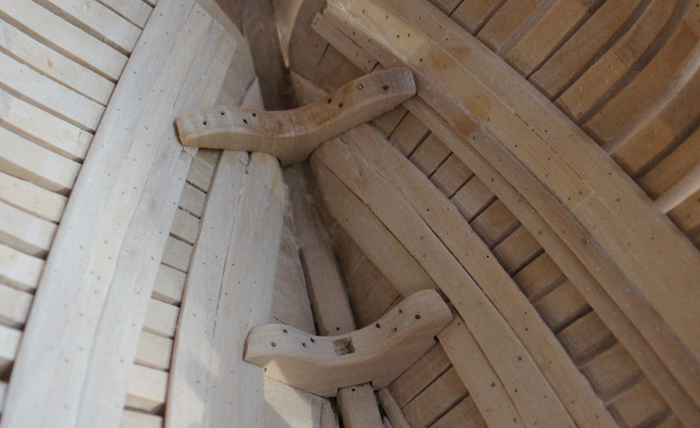
Lower Breast Hook
Author: Dan Vad. It’s just as well that we take plenty of pics of these bits, because they disappear completely later on. In fact, about the only way they’d ever be seen again is with an optic fibre or endoscope. Dan Vad.
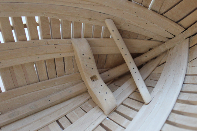
Oct. 8, 2012. I made one of the sleepers. These are knees that cross the lower transoms and the cant frames. This one cannot actually be used because the rest of the thickstuff has not been installed. There are supposed to be two bolts per transom according to TFFM but this just does not look right. Any thoughts?
Sleeper
Author: remcohe. Those are tricky to make. I just did one bolt per transom in a zig-zag pattern.

Author: druxey. One bolt per timber certainly looks neater. Those sleepers are very awkward to fit, and it looks like you’ve nailed it, Toni. I mean, bolted it. That doesn’t sound right either…
- archjofo, Jeronimo, Wishmaster and 2 others
-
5


HMS Atalanta 1775 by tlevine - FINISHED - 1:48 scale - from TFFM plans
in - Build logs for subjects built 1751 - 1800
Posted
Thanks, Danny. I am finding that, like everything else, it gets a little easier with practice. Those hanging knees are still a pain, though.
Greg, I started her in July, 2011. That puts me at least a year behind Danny!