

tlevine
-
Posts
1,966 -
Joined
-
Last visited
Reputation Activity
-

 tlevine got a reaction from MEDDO in NRG Rigging Project by tlevine - FINISHED
Most kits come with deadeyes and partially completed chains. Usually, the upper link (the link that goes around the deadeye) is pre-formed, with the bottom cut for insertion of the deadeye. Wire is provided for the builder to form the other two links but the entire assembly has very little strength and the cut ends of wire are ugly. The only way to make this assembly stronger and better looking is to solder the links closed. I prefer silver soldering, even though regular soldering will give sufficient strength. The benefit of silver soldering is that the metal is fused together rather than connected by a dissimilar metal, tin. This makes it easier to bend the part without worrying about the solder joint breaking. The downside is that there is a learning curve and the tools are more expensive. Silver solder also blackens well. There are also low melting point silver bearing solders (Tix) which can be blackened.
The measurements for all the parts of a British warship were determined by the Admiralty. There are reference books that contain this information such as Steel’s Tables. An easily read version of the tables is sold in the NRG store. The main mast diameter is given on the plans as 18”. Using the information from the tables, I determined that the main stay is 9” and the shrouds are 5.5”. Lines are measured by their circumference. The diameter of the deadeye is 1.5 times the size of the shroud or stay it is attached to, in this case 8 ¼”. A spreadsheet comes in handy in determining all the measurements.
Let me start by saying that my metal work has a bit to be desired. The chains are made from 1 ¼” wire, which is 22 gauge. I temper the wire by drawing it through a gas flame until it glows red. This makes the wire more malleable and removes any factory applied coating.
The deadeye chain is the same length for all the deadeyes. Make one and use it as a template for the others. I wrapped wire around the deadeye, leaving long tails, and inserted this into the slot in the channel. The tails were cut long enough to be able form the loop below the channel. I removed the deadeye and applied a finish.
The lower links are all the same length. From the plans I knew that the toe of the lower link is bolted 5” below the top of the wale and that its overall length was 9”. Two T-pins were inserted into the soldering board and the wire was wrapped around them, with the cut ends on the side. The middle link is different for every shroud because each is at a different angle to the mast as seen in the two pictures below. The link becomes longer with greater angulation of the shroud. You can see the difference in the shroud angles and how this would affect the length of the middle link.
To determine the angle of the chains, I put masking tape on the hull above and below the channel. A loop of rope was placed over the mast head and inserted through a slot in the channel. The angles made by the shroud were transferred to the tape. I dimpled the wale where the toe of the lower link and the lower preventer chain bolts will be located and removed the tape.
A hole was drilled through the wale where the toe of the lower link would later be bolted. The lower link and deadeye were temporarily installed. The length of the middle chains was determined by trial and error. With the deadeye and lower link in place, I formed the middle link from rope the same thickness as the wire and transferred those lengths to wire. I formed the middle link and soldered it closed, keeping the joint on one of the long sides. Then I inserted the lower link through the middle link and soldered it.
A T-pin was pushed into the soldering board and used to form the lower link toe. The lower link is also bent at the toe, allowing it to lay flat against the wale.
Finally, the wire for the upper link was passed through the middle link and soldered. The deadeye was inserted into the loop and the wire was crimped around it to fit into the channel slot, placing the solder joint in the slot camouflaged it.
And here are the ten chains, ready for blackening. The blackening chemical did not damage the wood deadeyes.
After blackening, the chains were installed. I have a piece of wire temporarily holding the lower link to the wale.
The preventer plate prevents the bolt securing the lower link from going all the way through the toe. It was made from square bar stock that was forged to the correct shape. Mine are made from sheet brass, cut and filed to the correct shape. Just like the middle links, they varied in length. The top of the plate makes a step over the bottom of the lower link toe to cover it. To determine the distance between the bolt holes on the plate, I measured the distance between the toe bolt and the previously marked lower preventer plate bolt and added the diameter of the wire the link was made from. The sequence is shown in the drawing below. After they were finished, they were blackened and installed.
To hold the upper links in the channels, a strip of molding was placed over them. Next up, the rigging begins.
-

-
tlevine reacted to Chuck in Sloop Speedwell 1752 by Chuck - Ketch Rigged Sloop - POF - prototype build
The knees wont be seen so they will be omitted. Its easy enough for folks to add should they want to. Thats a benefit of having Davids book while building the kit. But it will really complicate and make adding all of those ledges take forever. And all for something that will never be seen. I think most folks will be relieved not to make them.
the contemporary model doesnt have them either. My guess is for the very same reason.
It also reduces the cost and time to manufacture the kit quite a bit. I did add them on the fcastle however because the ends of the knees will be slightly visible in the open area left unplanked. So once the gun deck is planked…the casual viewer will actually assume you did add all of those knees for the entire model. LOL
I will take a picture with the planking templates in position. You will see what I am talking about pretty clearly. The same is true of all the ledges down the center line. They will not be seen either. The contemporary model also omits these..whats the point really.
-
tlevine reacted to Siggi52 in HMS Tiger 1747 by Siggi52 - 1:48 - 60 gun ship from NMM plans
Hello Chris,
no, I think not. It's the plan for the 1745 establishment and there the poop deck. At the QD are the cabins for the officers, and at the sheer plan is there nothing drawn. For the Tiger did't exist a plan for the poop deck. So at least I must not build there anything.
-
tlevine reacted to Siggi52 in HMS Tiger 1747 by Siggi52 - 1:48 - 60 gun ship from NMM plans
Hello, and many thanks for the likes
Today the carpenters build the grating over the lobby. All the beams are now fast, except the two in front of the bulwark.
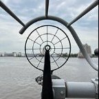
One question, did anybody know what these encircled parts should be? But before I start with planking, I think I build the wheels.
-
 tlevine got a reaction from CraigVT in Planking Tutorials PDFs
For those members who have never perused the Database section of MSW, here are the links to the planking tutorials by Antscherl and Passaro.
http://modelshipworldforum.com/resources/Framing_and_Planking/Planking primer.pdf
http://modelshipworldforum.com/resources/Framing_and_Planking/Lining Off your hull for planking.pdf
http://modelshipworldforum.com/resources/Framing_and_Planking/NailPatternJig.pdf
http://modelshipworldforum.com/resources/Framing_and_Planking/plankingfan.pdf
-
tlevine reacted to Chuck in Sloop Speedwell 1752 by Chuck - Ketch Rigged Sloop - POF - prototype build
I have reached another small milestone. All of the below deck fittings and cabins are completed. The gun deck is fully framed as well. Next up I will start planking the inboard bulwarks. That should make a huge difference.
I hope to see many of you this weekend at the New London show. It should be a very enjoyable weekend. I am looking forward to it.
Chuck
-
 tlevine got a reaction from ferretmary1 in Are you an NRG Member???
No time like the present to renew, Sam!
-
tlevine reacted to druxey in Beavers Prize 1777 by Mike Y - 1:48 - POF - Hahn style
Hahn was very clear that his models were stylized and did not reflect actual framing practice.
Also, the plans you show are of completely different ships. The upper one is Beaver's Prize dated March 1778 and the lower one is Beaver of 1757 - a French privateer.
-
tlevine reacted to dvm27 in HM Sloop Echo 1781 by VTHokiEE - 1:48 - Cross-Section
Instead of using fillers to repair the errant scores make a small patch using the same wood to fill in the defect. Make sure that the grain matches the direction of the carling (don't use end grain). Once glued in place and sanded flush the defect should be barely perceptible. I have corrected several errant mortises this way.
-
tlevine reacted to VTHokiEE in HM Sloop Echo 1781 by VTHokiEE - 1:48 - Cross-Section
Thanks @davec @Old Collingwood @glbarlow
I was happily continuing with the build when I unfortunately ran into a snag. There was a comment in @tlevine build log for the cross section "Do not measure off the practicum. Unlike the drawings in TFFM, these drawings are off scale by up to +/- 6%." Unfortunately, I re-read this caution late and now I am faced with an issue to resolve. I used the template provided on page 7 for the lower deck framing and realized that though the scale provided was measuring accurately the template would not fit the deck (it was too small). I made an executive decision to start at the provided centerline, place the carlings as indicated and continue on - this will prove to be an unfortunate mistake.
EDIT: The actual mistake was that I placed the template at the edge, by the frame, and measured out from there which allowed for too much space around the centerline. Based on measurements trying to correct this mistake if I actually had measured in from the centerline it would've been fine.
I placed the upper deck clamps, planking and spent some considerable time shaping the waterway.
I then started to think about the pump tubes and noticed that the carlings are not in the correct places. The most problematic are the interior ones in the aft - they landed right on top of the well and provide no space for the pump tubes to go into the well. This also means that the lower deck hatchway will be too large, but I can live with that mistake - I could also probably live with the error on the planked side in the aft and simply pretend that the carling was in the correct place. However, this error will not look right on the unplanned side and it will imply that the pump go through the well wall.
I think the best plan is to use some IPA and remove the most offensive two carlings, use filler (huge crossed fingers here) to hide to wrong scores, then carefully file new scores by hand (start crossing my toes here), and add the carlings back in.
-
tlevine reacted to Siggi52 in HMS Tiger 1747 by Siggi52 - 1:48 - 60 gun ship from NMM plans
Hello,
the last bulwark(?) between captains bed place and the lobby is installed.
Before I install the deck beams I have to make a decision, where to place the cannons? All sources say, there where 8 6 pdrs at the QD and 2 6 pdrs at the FC. But I never saw a model with a cannons at the FC! At least there is not so much space for cannons.
That cannon to the left has the problem with the shrouds, and the cannon to the right with the hight of the fife rail.
At least I could place all cannons at the QD, without one in the captain cabin. That would make the captain happy. And that is what you see at most of the models. If no one has a veto, I think I build it so.
-
tlevine reacted to druxey in Sloop Speedwell 1752 by Chuck - Ketch Rigged Sloop - POF - prototype build
Wait a moment - I've got a match here somewhere....
-
tlevine reacted to dvm27 in Sloop Speedwell 1752 by Chuck - Ketch Rigged Sloop - POF - prototype build
The officer gets a spoon and cup (great details by the way) but no light in the filling room? I think OSHA would level a fine for that.
-
tlevine reacted to Chuck in Sloop Speedwell 1752 by Chuck - Ketch Rigged Sloop - POF - prototype build
Thank You...
The cabins on the aft lower platform are completed. No detailed explanation since they are built exactly like the others. Each partition wall is built up with two layers glued together. Then they are detailed with hinges and door handles as required along with any upright timbers 1/8" x 1/8" strips. Their heights and widths are adjusted to fit under the deck beams etc. Finally they are assembled and glued into position.
Here is the tiny powder and filling rooms completed. These walls are slightly thicker than the other cabins as was normally the case. An extra laser cut sheet of parts shows how all the cabins are prepared for you. They are all numbered and shown on the plans. I built them in the order that they are numbered.
All of the cabins completed.
Next up is to complete the remaining deck beams carlings and ledges.
-
tlevine reacted to Erik W in HM Cutter Cheerful 1806 by Erik W - 1:48 scale
I finished the deadeyes and deadeye strops this week. And set a new personal record for the most discarded/rejected parts. Haha. I can laugh now, but at the time, it was the height of frustration. I think to get the 8 usable deadeye strops shaped correctly and mounted, I wound up with an additional 15 or so I scrapped. Admittedly most of that was trying to get the first couple formed. Once I had a system down for shaping them, things went more smoothly. I wound up chipping the paint off some of the chain plates, so had to touch that up. And I wound up rubbing off the finish of the annealed wire I used for making the strops from handling too much, so had to blacken those again . . . which made a bit of a mess on the deadeyes from blackening smudges coming off of my fingers. So, I had to re-sand some of the deadeyes to remove that. All in all not the most fun part of the build. So, I'm happy that buttons up Chapter 9 of Chuck's monograph, and I look forward to getting away from handling metal and back to working with wood for the next parts of the build!
Erik
-
tlevine reacted to archjofo in La Créole 1827 by archjofo - Scale 1/48 - French corvette
Hello,
A while back, I captured some general shots of the model. It remains under a dust cover while I´m outfitting the yards. Regrettably, I don't have any recent pictures available right now.
-
tlevine reacted to archjofo in La Créole 1827 by archjofo - Scale 1/48 - French corvette
@druxey
Hello,
I'm glad you like it. Thanks !
I would also like to thank everyone else for the LIKES.
Continuation: Equipment of the mizzen topgallant yard – Vergue de perruche
After a suggestion from model building colleagues, I secured the mousing of the hook for the tye with a thinner three strand rope with a diameter of 0.15 mm that was specially made for this purpose.
We then continued with the quarter blocks (clew lines and sheets), which are among the smallest double blocks on the model.
For the block ropes I used ropes with a diameter of 0.25 mm, which were served with silk yarn.
The last two pictures show the arrangement of the quarter blocks with the truss already attached.
Up soon …
-
tlevine reacted to giampieroricci in HMS PEGASUS by giampieroricci - Scale 1:36 - Swan-Class Sloop from plans by David Antscherl & Greg Herbert
chesstree, fenders and the entry steps:
-

 tlevine got a reaction from Nirvana in NRG Rigging Project by tlevine - FINISHED
The mast cap has two openings: a round one for the topmast and a square one for the lower mast head. There are four eyebolts that extend all the way through the mast cap. I raided my scrap box for a contrasting color piece of wood. Both openings were made with a regular drill. The square opening was then shaped with a chisel and the round one was enlarged with sandpaper wrapped around a dowel. It will not be installed until much later.
Although it also will not be installed for a while, I made the topmast next. The dimensions of the topmast are determined by the diameter of the lower mast. The lower end of topmast is 7/10 the diameter of the mast and the upper end is 11/20. This will be a stub topmast as the actual length of this mast would be 8” on the model. Its shape is more complicated than the lower mast. The lowest section (the block) is octagonal, the next section is (the heel) square, followed by another octagonal section. The upper part of the topmast is round, tapering as it goes to the head. There are three openings in the mast; the middle one is for the fid (the rectangular peg which prevents the mast from falling between the trestle trees) and the other two are for sheaves. The kit will contain a template for the topmast.
Starting with a ¼” square dowel, I marked out the mast for the various transition points. Using the 7:10:7 ratio for determining the corners of the octagon, I drew the lines for those two sections. The mast taper begins at the end of the upper octagon. The blue line is the centerline and the red lines are the corners of the octagons. Just as was done for the main mast, I taped off the square section to protect it from errant chisel cuts. The pictures shows a completed topmast above a square dowel. There is extra wood on the top and bottom of the dowel for ease of handling.
I used a saw to cut a shallow groove between the octagonal and square areas on the corners of the square section (circled area). This transition should stay sharp. The lower octagonal section was shaped with a sanding stick.
The upper octagon and round area were both shaped as octagons, without any taper.
Another piece of tape was used to protect the upper octagon and the upper part of the mast was rounded and tapered.
After removing the tape, the transition between the octagonal and round sections and between the square and upper octagonal sections were smoothed.
Making the holes for two sheaves and the fid was next. The upper and lower sheave openings are in the octagonal sections and are 90 degrees to each other and 45 degrees to the fid hole. The dimensions for the fid opening are one-third the mast diameter high and one-quarter the mast diameter wide, in this case 3” x 2.5”. The opening was formed from multiple drill holes, squared off with a #11 blade. The fid was made slightly smaller than the size of the opening and long enough to span the trestle trees.
The sheave openings are 8” long and 1.5” wide. I simulated the sheaves on this model. These were trickier to drill accurately because they are on angled faces. Here is how I made them. The sheave opening was marked on both sides of the mast. I put the mast in a vise, clamping it in the upper octagonal area, just above the sheave opening. A small hole was drilled near the top and bottom of the sheave opening but I did not drill completely through the mast. The mast was repositioned in the vise and the holes on the other side were drilled. The holes on each side were enlarged to the correct width of the opening. I did this slowly, working a little bit on one side and then switching to the other side. The holes eventually met. Then, using a #11 blade, a shallow groove representing the sheave was formed between the two holes and the “sheave” was painted. The final step was to cut off the excess wood at the top and bottom of the topmast and apply a finish.
This is how it looked installed.
-

 tlevine got a reaction from thibaultron in NRG Rigging Project by tlevine - FINISHED
At this point videos are not planned. There is more detail in the monograph and, if you purchase the kit, I would be available for questions. The Guild hopes to have it available in 4-6 weeks.
-
tlevine got a reaction from thibaultron in NRG Rigging Project by tlevine - FINISHED
Thanks, Tom. Sorry for the delayed response but I was on the road and without internet access.
-
 tlevine got a reaction from Canute in NRG Rigging Project by tlevine - FINISHED
At this point videos are not planned. There is more detail in the monograph and, if you purchase the kit, I would be available for questions. The Guild hopes to have it available in 4-6 weeks.
-
 tlevine got a reaction from Mr Whippy in 18th-Century Merchantman Half-Hull Planking Project by mtaylor - NRG
I hope you enjoy it, Mark. Last Fall I had a group of six modelers who I assisted with the kit, getting together for a half-day, every other week. It was a lot of fun for all of us.
-
tlevine got a reaction from Canute in NRG Rigging Project by tlevine - FINISHED
Thanks, Tom. Sorry for the delayed response but I was on the road and without internet access.