

tlevine
-
Posts
1,947 -
Joined
-
Last visited
Reputation Activity
-

 tlevine got a reaction from mtaylor in How much more difficult is it to cut and lay individual deck planks vs full length strips?
Or in easy to read tables here https://thenrgstore.org/collections/books-and-practicums/products/steels-tables-of-the-dimensions-of-a-ship-of-each-class-in-the-british-navy
-
 tlevine reacted to Erik W in HM Cutter Cheerful 1806 by Erik W - 1:48 scale
This was a fun week. I finished the stern details. These included building the second seat, which I'm happy to say is close to identical to the first. I made the horse for the boom sheet out of 22 gauge annealed wire, with washers made from .062" diameter styrene rod with the center .028" drilled out for the wire. I cut and formed the transom knees, and glued those on. I then shaped and added the cleats. These I had bought from Chuck a long time ago. I see he currently offers cleats in 5mm, 7mm, and 9mm. I have 9mm and 6mm on hand. So for the cleats on the transom knees, I shortened the 6mm to 5mm, and used the 9mm and 6mm cleats in the other areas of the stern. I see in these enlarged photos a couple of spots that need touching up, but I'm otherwise happy with the way these details turned out.
Erik
-
 tlevine got a reaction from Thukydides in How much more difficult is it to cut and lay individual deck planks vs full length strips?
Or in easy to read tables here https://thenrgstore.org/collections/books-and-practicums/products/steels-tables-of-the-dimensions-of-a-ship-of-each-class-in-the-british-navy
-

 tlevine got a reaction from thibaultron in NRG Rigging Project by tlevine
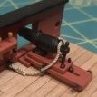
The futtock staves were made from 3” served rope and are located as far below the trestle trees as the top of the mast is above the trestle trees, approximately seven feet. For ease of installation, I used served 24 gauge wire, rather than rope. They were lashed to the shrouds. The picture on the left shows the lashing in white for clarity and the finished product on the right.
And now it is time for the dreaded ratlines. There are some lines on a ship that are a do not change with the size of the ship, such as the footropes and ratlines, both of which must hold a seaman’s weight. The ratlines are made of tarred 1.5” rope. At this scale, I simply tied, rather than lashed, them to the outer shrouds. They are secured to the inner shrouds with clove hitch knots, a drawing of which is below. This picture is also from The Boy’s Manual.
Ratlines are spaced 12-15” apart and are parallel to the waterline. The easiest way to keep them even is to make a line jig. There is a tendency to pull the shrouds inward as the ratlines are added. I like to secure a brass rod or stick to the outer shrouds to keep them straight. This is my setup. The clips are holding the line jig in place. The ratlines are parallel to the waterline, not to the deck. After several hours, 220 knots and fifteen scale feet of rope, the ratlines were finished.
Catharpins are ropes with an eye at each end which extend across and are seized to the shrouds at the level of the futtock staves. According to Steel, sloops were not equipped with catharpins but I included them in the kit to illustrate their construction. I made them from 22 gauge wire with a loop on each end. As there is no tension on them, I did not solder the loops closed. The catharpins are served and the ends are painted black to simulate the eye splice. The first catharpin is located just aft of the mast and the other two are spaced out evenly along the futtock stave.
This completed the standing rigging of the lower mast. As mentioned earlier, because this is a cross section model, lines that would not terminate on the model, such as the stays and backstays, were omitted.
-
 tlevine got a reaction from KentM in NRG Rigging Project by tlevine
The futtock staves were made from 3” served rope and are located as far below the trestle trees as the top of the mast is above the trestle trees, approximately seven feet. For ease of installation, I used served 24 gauge wire, rather than rope. They were lashed to the shrouds. The picture on the left shows the lashing in white for clarity and the finished product on the right.
And now it is time for the dreaded ratlines. There are some lines on a ship that are a do not change with the size of the ship, such as the footropes and ratlines, both of which must hold a seaman’s weight. The ratlines are made of tarred 1.5” rope. At this scale, I simply tied, rather than lashed, them to the outer shrouds. They are secured to the inner shrouds with clove hitch knots, a drawing of which is below. This picture is also from The Boy’s Manual.
Ratlines are spaced 12-15” apart and are parallel to the waterline. The easiest way to keep them even is to make a line jig. There is a tendency to pull the shrouds inward as the ratlines are added. I like to secure a brass rod or stick to the outer shrouds to keep them straight. This is my setup. The clips are holding the line jig in place. The ratlines are parallel to the waterline, not to the deck. After several hours, 220 knots and fifteen scale feet of rope, the ratlines were finished.
Catharpins are ropes with an eye at each end which extend across and are seized to the shrouds at the level of the futtock staves. According to Steel, sloops were not equipped with catharpins but I included them in the kit to illustrate their construction. I made them from 22 gauge wire with a loop on each end. As there is no tension on them, I did not solder the loops closed. The catharpins are served and the ends are painted black to simulate the eye splice. The first catharpin is located just aft of the mast and the other two are spaced out evenly along the futtock stave.
This completed the standing rigging of the lower mast. As mentioned earlier, because this is a cross section model, lines that would not terminate on the model, such as the stays and backstays, were omitted.
-
 tlevine got a reaction from MEDDO in NRG Rigging Project by tlevine
The futtock staves were made from 3” served rope and are located as far below the trestle trees as the top of the mast is above the trestle trees, approximately seven feet. For ease of installation, I used served 24 gauge wire, rather than rope. They were lashed to the shrouds. The picture on the left shows the lashing in white for clarity and the finished product on the right.
And now it is time for the dreaded ratlines. There are some lines on a ship that are a do not change with the size of the ship, such as the footropes and ratlines, both of which must hold a seaman’s weight. The ratlines are made of tarred 1.5” rope. At this scale, I simply tied, rather than lashed, them to the outer shrouds. They are secured to the inner shrouds with clove hitch knots, a drawing of which is below. This picture is also from The Boy’s Manual.
Ratlines are spaced 12-15” apart and are parallel to the waterline. The easiest way to keep them even is to make a line jig. There is a tendency to pull the shrouds inward as the ratlines are added. I like to secure a brass rod or stick to the outer shrouds to keep them straight. This is my setup. The clips are holding the line jig in place. The ratlines are parallel to the waterline, not to the deck. After several hours, 220 knots and fifteen scale feet of rope, the ratlines were finished.
Catharpins are ropes with an eye at each end which extend across and are seized to the shrouds at the level of the futtock staves. According to Steel, sloops were not equipped with catharpins but I included them in the kit to illustrate their construction. I made them from 22 gauge wire with a loop on each end. As there is no tension on them, I did not solder the loops closed. The catharpins are served and the ends are painted black to simulate the eye splice. The first catharpin is located just aft of the mast and the other two are spaced out evenly along the futtock stave.
This completed the standing rigging of the lower mast. As mentioned earlier, because this is a cross section model, lines that would not terminate on the model, such as the stays and backstays, were omitted.
-
tlevine got a reaction from thibaultron in NRG Rigging Project by tlevine
The shrouds were installed next. The starboard shroud is always placed first and are they are installed from fore to aft. Because this ship has an odd number of shrouds, the first shroud is single; the rest are double. The first shroud is served its entire length, protecting it from the lower sail. The starboard and port first shrouds are secured to each other with a cut splice, just as was done with the pendant tackle.
The remaining paired shrouds are served where they could be chafed: the center 20-25%, based on the ship being rigged. I cut a two foot piece of line and marked the midpoint and 10% the length of the shroud on either side of the midpoint, in this case 1.2”. This is the area that was served. The doubled shrouds were secured with a throat seizing tight to the mast head. The lower ends of the served portion of the shrouds should be level when they are installed. This means that the throat seizing is not exactly in the middle of the served section, but offset enough to allow this to occur. You can see this in the next picture. The aft shroud seizing is slightly longer than the fore.
The shrouds were installed, alternating starboard and port, taking care to stack them neatly. The topmast is temporarily installed in the following pictures.
The next step was to attach the upper deadeyes to the shrouds. The distance between the upper and lower deadeyes is a constant. The easiest way to ensure this is to make a spacer jig. You will actually need ten, five for each side. The picture shows two jigs. The one on the left is made by soldering the two wires together. The other one uses twisted wire. The prongs go through the two inner deadeye holes.
I started by inserting the prongs through the upper holes of the lower deadeye and bent the wire around the back of the deadeye to prevent it from coming out. Next, I wrapped the shroud around the upper deadeye and adjusted the shroud length so that the upper deadeye could be threaded onto the jig. These shrouds are cable laid (left twist), so the short end of the shroud went on the aft side of the shroud. If the shrouds were rope (right twist), the short end would be on the fore side. I secured the shrouds to the deadeyes with alligator clips. I find it important to leave the model alone for several hours at this point. This allows the rope to stretch and helps prevent sagging in the future.
The upper deadeyes are secured with three seizings. A cross seizing was placed where the shroud crossed over itself next to the deadeye. I marked the location of the cross seizing on both sides of the shroud and removed the deadeye. If left in, the loop is too big. After making the cross seizing, the deadeye was reinserted and the middle and end round seizings were added. The drawing shows a round seizing.
And the picture illustrates the relative location of the seizings, using white thread to make it easier for you to see.
Brown paint was used to represent the leather cap at the end of the shroud.
The shroud lanyards were installed next. They are considered running rigging and are not tarred. A knot was tied at the end of the lanyard and it was inserted through the back of the upper deadeye in the foremost hole. After reeving it through the deadeye, excess line was kept for tying off. Once they were done, the lanyards were gradually tightened, making sure the mast was straight. Just like with the shrouds, I gave it a few hours to allow the line to stretch. To tie off the lanyard, the rope was passed between the shroud and the deadeye (below left) and looped under the last line of the lanyard (below right). The lanyard was wrapped around the shroud a few times and finished by inserting it under the last loop.
-
 tlevine got a reaction from robert952 in NRG Rigging Project by tlevine
The futtock staves were made from 3” served rope and are located as far below the trestle trees as the top of the mast is above the trestle trees, approximately seven feet. For ease of installation, I used served 24 gauge wire, rather than rope. They were lashed to the shrouds. The picture on the left shows the lashing in white for clarity and the finished product on the right.
And now it is time for the dreaded ratlines. There are some lines on a ship that are a do not change with the size of the ship, such as the footropes and ratlines, both of which must hold a seaman’s weight. The ratlines are made of tarred 1.5” rope. At this scale, I simply tied, rather than lashed, them to the outer shrouds. They are secured to the inner shrouds with clove hitch knots, a drawing of which is below. This picture is also from The Boy’s Manual.
Ratlines are spaced 12-15” apart and are parallel to the waterline. The easiest way to keep them even is to make a line jig. There is a tendency to pull the shrouds inward as the ratlines are added. I like to secure a brass rod or stick to the outer shrouds to keep them straight. This is my setup. The clips are holding the line jig in place. The ratlines are parallel to the waterline, not to the deck. After several hours, 220 knots and fifteen scale feet of rope, the ratlines were finished.
Catharpins are ropes with an eye at each end which extend across and are seized to the shrouds at the level of the futtock staves. According to Steel, sloops were not equipped with catharpins but I included them in the kit to illustrate their construction. I made them from 22 gauge wire with a loop on each end. As there is no tension on them, I did not solder the loops closed. The catharpins are served and the ends are painted black to simulate the eye splice. The first catharpin is located just aft of the mast and the other two are spaced out evenly along the futtock stave.
This completed the standing rigging of the lower mast. As mentioned earlier, because this is a cross section model, lines that would not terminate on the model, such as the stays and backstays, were omitted.
-
 tlevine got a reaction from allanyed in How much more difficult is it to cut and lay individual deck planks vs full length strips?
Or in easy to read tables here https://thenrgstore.org/collections/books-and-practicums/products/steels-tables-of-the-dimensions-of-a-ship-of-each-class-in-the-british-navy
-
 tlevine got a reaction from _SalD_ in NRG Rigging Project by tlevine
The futtock staves were made from 3” served rope and are located as far below the trestle trees as the top of the mast is above the trestle trees, approximately seven feet. For ease of installation, I used served 24 gauge wire, rather than rope. They were lashed to the shrouds. The picture on the left shows the lashing in white for clarity and the finished product on the right.
And now it is time for the dreaded ratlines. There are some lines on a ship that are a do not change with the size of the ship, such as the footropes and ratlines, both of which must hold a seaman’s weight. The ratlines are made of tarred 1.5” rope. At this scale, I simply tied, rather than lashed, them to the outer shrouds. They are secured to the inner shrouds with clove hitch knots, a drawing of which is below. This picture is also from The Boy’s Manual.
Ratlines are spaced 12-15” apart and are parallel to the waterline. The easiest way to keep them even is to make a line jig. There is a tendency to pull the shrouds inward as the ratlines are added. I like to secure a brass rod or stick to the outer shrouds to keep them straight. This is my setup. The clips are holding the line jig in place. The ratlines are parallel to the waterline, not to the deck. After several hours, 220 knots and fifteen scale feet of rope, the ratlines were finished.
Catharpins are ropes with an eye at each end which extend across and are seized to the shrouds at the level of the futtock staves. According to Steel, sloops were not equipped with catharpins but I included them in the kit to illustrate their construction. I made them from 22 gauge wire with a loop on each end. As there is no tension on them, I did not solder the loops closed. The catharpins are served and the ends are painted black to simulate the eye splice. The first catharpin is located just aft of the mast and the other two are spaced out evenly along the futtock stave.
This completed the standing rigging of the lower mast. As mentioned earlier, because this is a cross section model, lines that would not terminate on the model, such as the stays and backstays, were omitted.
-
 tlevine got a reaction from Canute in NRG Rigging Project by tlevine
The futtock staves were made from 3” served rope and are located as far below the trestle trees as the top of the mast is above the trestle trees, approximately seven feet. For ease of installation, I used served 24 gauge wire, rather than rope. They were lashed to the shrouds. The picture on the left shows the lashing in white for clarity and the finished product on the right.
And now it is time for the dreaded ratlines. There are some lines on a ship that are a do not change with the size of the ship, such as the footropes and ratlines, both of which must hold a seaman’s weight. The ratlines are made of tarred 1.5” rope. At this scale, I simply tied, rather than lashed, them to the outer shrouds. They are secured to the inner shrouds with clove hitch knots, a drawing of which is below. This picture is also from The Boy’s Manual.
Ratlines are spaced 12-15” apart and are parallel to the waterline. The easiest way to keep them even is to make a line jig. There is a tendency to pull the shrouds inward as the ratlines are added. I like to secure a brass rod or stick to the outer shrouds to keep them straight. This is my setup. The clips are holding the line jig in place. The ratlines are parallel to the waterline, not to the deck. After several hours, 220 knots and fifteen scale feet of rope, the ratlines were finished.
Catharpins are ropes with an eye at each end which extend across and are seized to the shrouds at the level of the futtock staves. According to Steel, sloops were not equipped with catharpins but I included them in the kit to illustrate their construction. I made them from 22 gauge wire with a loop on each end. As there is no tension on them, I did not solder the loops closed. The catharpins are served and the ends are painted black to simulate the eye splice. The first catharpin is located just aft of the mast and the other two are spaced out evenly along the futtock stave.
This completed the standing rigging of the lower mast. As mentioned earlier, because this is a cross section model, lines that would not terminate on the model, such as the stays and backstays, were omitted.
-
 tlevine got a reaction from JpR62 in NRG Rigging Project by tlevine
The futtock staves were made from 3” served rope and are located as far below the trestle trees as the top of the mast is above the trestle trees, approximately seven feet. For ease of installation, I used served 24 gauge wire, rather than rope. They were lashed to the shrouds. The picture on the left shows the lashing in white for clarity and the finished product on the right.
And now it is time for the dreaded ratlines. There are some lines on a ship that are a do not change with the size of the ship, such as the footropes and ratlines, both of which must hold a seaman’s weight. The ratlines are made of tarred 1.5” rope. At this scale, I simply tied, rather than lashed, them to the outer shrouds. They are secured to the inner shrouds with clove hitch knots, a drawing of which is below. This picture is also from The Boy’s Manual.
Ratlines are spaced 12-15” apart and are parallel to the waterline. The easiest way to keep them even is to make a line jig. There is a tendency to pull the shrouds inward as the ratlines are added. I like to secure a brass rod or stick to the outer shrouds to keep them straight. This is my setup. The clips are holding the line jig in place. The ratlines are parallel to the waterline, not to the deck. After several hours, 220 knots and fifteen scale feet of rope, the ratlines were finished.
Catharpins are ropes with an eye at each end which extend across and are seized to the shrouds at the level of the futtock staves. According to Steel, sloops were not equipped with catharpins but I included them in the kit to illustrate their construction. I made them from 22 gauge wire with a loop on each end. As there is no tension on them, I did not solder the loops closed. The catharpins are served and the ends are painted black to simulate the eye splice. The first catharpin is located just aft of the mast and the other two are spaced out evenly along the futtock stave.
This completed the standing rigging of the lower mast. As mentioned earlier, because this is a cross section model, lines that would not terminate on the model, such as the stays and backstays, were omitted.
-
 tlevine got a reaction from CiscoH in NRG Rigging Project by tlevine
The futtock staves were made from 3” served rope and are located as far below the trestle trees as the top of the mast is above the trestle trees, approximately seven feet. For ease of installation, I used served 24 gauge wire, rather than rope. They were lashed to the shrouds. The picture on the left shows the lashing in white for clarity and the finished product on the right.
And now it is time for the dreaded ratlines. There are some lines on a ship that are a do not change with the size of the ship, such as the footropes and ratlines, both of which must hold a seaman’s weight. The ratlines are made of tarred 1.5” rope. At this scale, I simply tied, rather than lashed, them to the outer shrouds. They are secured to the inner shrouds with clove hitch knots, a drawing of which is below. This picture is also from The Boy’s Manual.
Ratlines are spaced 12-15” apart and are parallel to the waterline. The easiest way to keep them even is to make a line jig. There is a tendency to pull the shrouds inward as the ratlines are added. I like to secure a brass rod or stick to the outer shrouds to keep them straight. This is my setup. The clips are holding the line jig in place. The ratlines are parallel to the waterline, not to the deck. After several hours, 220 knots and fifteen scale feet of rope, the ratlines were finished.
Catharpins are ropes with an eye at each end which extend across and are seized to the shrouds at the level of the futtock staves. According to Steel, sloops were not equipped with catharpins but I included them in the kit to illustrate their construction. I made them from 22 gauge wire with a loop on each end. As there is no tension on them, I did not solder the loops closed. The catharpins are served and the ends are painted black to simulate the eye splice. The first catharpin is located just aft of the mast and the other two are spaced out evenly along the futtock stave.
This completed the standing rigging of the lower mast. As mentioned earlier, because this is a cross section model, lines that would not terminate on the model, such as the stays and backstays, were omitted.
-
 tlevine got a reaction from Dlowder in NRG Rigging Project by tlevine
The futtock staves were made from 3” served rope and are located as far below the trestle trees as the top of the mast is above the trestle trees, approximately seven feet. For ease of installation, I used served 24 gauge wire, rather than rope. They were lashed to the shrouds. The picture on the left shows the lashing in white for clarity and the finished product on the right.
And now it is time for the dreaded ratlines. There are some lines on a ship that are a do not change with the size of the ship, such as the footropes and ratlines, both of which must hold a seaman’s weight. The ratlines are made of tarred 1.5” rope. At this scale, I simply tied, rather than lashed, them to the outer shrouds. They are secured to the inner shrouds with clove hitch knots, a drawing of which is below. This picture is also from The Boy’s Manual.
Ratlines are spaced 12-15” apart and are parallel to the waterline. The easiest way to keep them even is to make a line jig. There is a tendency to pull the shrouds inward as the ratlines are added. I like to secure a brass rod or stick to the outer shrouds to keep them straight. This is my setup. The clips are holding the line jig in place. The ratlines are parallel to the waterline, not to the deck. After several hours, 220 knots and fifteen scale feet of rope, the ratlines were finished.
Catharpins are ropes with an eye at each end which extend across and are seized to the shrouds at the level of the futtock staves. According to Steel, sloops were not equipped with catharpins but I included them in the kit to illustrate their construction. I made them from 22 gauge wire with a loop on each end. As there is no tension on them, I did not solder the loops closed. The catharpins are served and the ends are painted black to simulate the eye splice. The first catharpin is located just aft of the mast and the other two are spaced out evenly along the futtock stave.
This completed the standing rigging of the lower mast. As mentioned earlier, because this is a cross section model, lines that would not terminate on the model, such as the stays and backstays, were omitted.
-
 tlevine got a reaction from rlb in NRG Rigging Project by tlevine
The futtock staves were made from 3” served rope and are located as far below the trestle trees as the top of the mast is above the trestle trees, approximately seven feet. For ease of installation, I used served 24 gauge wire, rather than rope. They were lashed to the shrouds. The picture on the left shows the lashing in white for clarity and the finished product on the right.
And now it is time for the dreaded ratlines. There are some lines on a ship that are a do not change with the size of the ship, such as the footropes and ratlines, both of which must hold a seaman’s weight. The ratlines are made of tarred 1.5” rope. At this scale, I simply tied, rather than lashed, them to the outer shrouds. They are secured to the inner shrouds with clove hitch knots, a drawing of which is below. This picture is also from The Boy’s Manual.
Ratlines are spaced 12-15” apart and are parallel to the waterline. The easiest way to keep them even is to make a line jig. There is a tendency to pull the shrouds inward as the ratlines are added. I like to secure a brass rod or stick to the outer shrouds to keep them straight. This is my setup. The clips are holding the line jig in place. The ratlines are parallel to the waterline, not to the deck. After several hours, 220 knots and fifteen scale feet of rope, the ratlines were finished.
Catharpins are ropes with an eye at each end which extend across and are seized to the shrouds at the level of the futtock staves. According to Steel, sloops were not equipped with catharpins but I included them in the kit to illustrate their construction. I made them from 22 gauge wire with a loop on each end. As there is no tension on them, I did not solder the loops closed. The catharpins are served and the ends are painted black to simulate the eye splice. The first catharpin is located just aft of the mast and the other two are spaced out evenly along the futtock stave.
This completed the standing rigging of the lower mast. As mentioned earlier, because this is a cross section model, lines that would not terminate on the model, such as the stays and backstays, were omitted.
-
.jpg.d84ec4dad1d7791e855dca06210ab6f3.thumb.jpg.f45209242e851d4409eca1a09293165b.jpg) tlevine got a reaction from hollowneck in NRG Rigging Project by tlevine
tlevine got a reaction from hollowneck in NRG Rigging Project by tlevine
The futtock staves were made from 3” served rope and are located as far below the trestle trees as the top of the mast is above the trestle trees, approximately seven feet. For ease of installation, I used served 24 gauge wire, rather than rope. They were lashed to the shrouds. The picture on the left shows the lashing in white for clarity and the finished product on the right.
And now it is time for the dreaded ratlines. There are some lines on a ship that are a do not change with the size of the ship, such as the footropes and ratlines, both of which must hold a seaman’s weight. The ratlines are made of tarred 1.5” rope. At this scale, I simply tied, rather than lashed, them to the outer shrouds. They are secured to the inner shrouds with clove hitch knots, a drawing of which is below. This picture is also from The Boy’s Manual.
Ratlines are spaced 12-15” apart and are parallel to the waterline. The easiest way to keep them even is to make a line jig. There is a tendency to pull the shrouds inward as the ratlines are added. I like to secure a brass rod or stick to the outer shrouds to keep them straight. This is my setup. The clips are holding the line jig in place. The ratlines are parallel to the waterline, not to the deck. After several hours, 220 knots and fifteen scale feet of rope, the ratlines were finished.
Catharpins are ropes with an eye at each end which extend across and are seized to the shrouds at the level of the futtock staves. According to Steel, sloops were not equipped with catharpins but I included them in the kit to illustrate their construction. I made them from 22 gauge wire with a loop on each end. As there is no tension on them, I did not solder the loops closed. The catharpins are served and the ends are painted black to simulate the eye splice. The first catharpin is located just aft of the mast and the other two are spaced out evenly along the futtock stave.
This completed the standing rigging of the lower mast. As mentioned earlier, because this is a cross section model, lines that would not terminate on the model, such as the stays and backstays, were omitted.
-
 tlevine got a reaction from gjdale in NRG Rigging Project by tlevine
The futtock staves were made from 3” served rope and are located as far below the trestle trees as the top of the mast is above the trestle trees, approximately seven feet. For ease of installation, I used served 24 gauge wire, rather than rope. They were lashed to the shrouds. The picture on the left shows the lashing in white for clarity and the finished product on the right.
And now it is time for the dreaded ratlines. There are some lines on a ship that are a do not change with the size of the ship, such as the footropes and ratlines, both of which must hold a seaman’s weight. The ratlines are made of tarred 1.5” rope. At this scale, I simply tied, rather than lashed, them to the outer shrouds. They are secured to the inner shrouds with clove hitch knots, a drawing of which is below. This picture is also from The Boy’s Manual.
Ratlines are spaced 12-15” apart and are parallel to the waterline. The easiest way to keep them even is to make a line jig. There is a tendency to pull the shrouds inward as the ratlines are added. I like to secure a brass rod or stick to the outer shrouds to keep them straight. This is my setup. The clips are holding the line jig in place. The ratlines are parallel to the waterline, not to the deck. After several hours, 220 knots and fifteen scale feet of rope, the ratlines were finished.
Catharpins are ropes with an eye at each end which extend across and are seized to the shrouds at the level of the futtock staves. According to Steel, sloops were not equipped with catharpins but I included them in the kit to illustrate their construction. I made them from 22 gauge wire with a loop on each end. As there is no tension on them, I did not solder the loops closed. The catharpins are served and the ends are painted black to simulate the eye splice. The first catharpin is located just aft of the mast and the other two are spaced out evenly along the futtock stave.
This completed the standing rigging of the lower mast. As mentioned earlier, because this is a cross section model, lines that would not terminate on the model, such as the stays and backstays, were omitted.
-
 tlevine got a reaction from BenD in NRG Rigging Project by tlevine
The futtock staves were made from 3” served rope and are located as far below the trestle trees as the top of the mast is above the trestle trees, approximately seven feet. For ease of installation, I used served 24 gauge wire, rather than rope. They were lashed to the shrouds. The picture on the left shows the lashing in white for clarity and the finished product on the right.
And now it is time for the dreaded ratlines. There are some lines on a ship that are a do not change with the size of the ship, such as the footropes and ratlines, both of which must hold a seaman’s weight. The ratlines are made of tarred 1.5” rope. At this scale, I simply tied, rather than lashed, them to the outer shrouds. They are secured to the inner shrouds with clove hitch knots, a drawing of which is below. This picture is also from The Boy’s Manual.
Ratlines are spaced 12-15” apart and are parallel to the waterline. The easiest way to keep them even is to make a line jig. There is a tendency to pull the shrouds inward as the ratlines are added. I like to secure a brass rod or stick to the outer shrouds to keep them straight. This is my setup. The clips are holding the line jig in place. The ratlines are parallel to the waterline, not to the deck. After several hours, 220 knots and fifteen scale feet of rope, the ratlines were finished.
Catharpins are ropes with an eye at each end which extend across and are seized to the shrouds at the level of the futtock staves. According to Steel, sloops were not equipped with catharpins but I included them in the kit to illustrate their construction. I made them from 22 gauge wire with a loop on each end. As there is no tension on them, I did not solder the loops closed. The catharpins are served and the ends are painted black to simulate the eye splice. The first catharpin is located just aft of the mast and the other two are spaced out evenly along the futtock stave.
This completed the standing rigging of the lower mast. As mentioned earlier, because this is a cross section model, lines that would not terminate on the model, such as the stays and backstays, were omitted.
-
tlevine got a reaction from KentM in NRG Rigging Project by tlevine
The shrouds were installed next. The starboard shroud is always placed first and are they are installed from fore to aft. Because this ship has an odd number of shrouds, the first shroud is single; the rest are double. The first shroud is served its entire length, protecting it from the lower sail. The starboard and port first shrouds are secured to each other with a cut splice, just as was done with the pendant tackle.
The remaining paired shrouds are served where they could be chafed: the center 20-25%, based on the ship being rigged. I cut a two foot piece of line and marked the midpoint and 10% the length of the shroud on either side of the midpoint, in this case 1.2”. This is the area that was served. The doubled shrouds were secured with a throat seizing tight to the mast head. The lower ends of the served portion of the shrouds should be level when they are installed. This means that the throat seizing is not exactly in the middle of the served section, but offset enough to allow this to occur. You can see this in the next picture. The aft shroud seizing is slightly longer than the fore.
The shrouds were installed, alternating starboard and port, taking care to stack them neatly. The topmast is temporarily installed in the following pictures.
The next step was to attach the upper deadeyes to the shrouds. The distance between the upper and lower deadeyes is a constant. The easiest way to ensure this is to make a spacer jig. You will actually need ten, five for each side. The picture shows two jigs. The one on the left is made by soldering the two wires together. The other one uses twisted wire. The prongs go through the two inner deadeye holes.
I started by inserting the prongs through the upper holes of the lower deadeye and bent the wire around the back of the deadeye to prevent it from coming out. Next, I wrapped the shroud around the upper deadeye and adjusted the shroud length so that the upper deadeye could be threaded onto the jig. These shrouds are cable laid (left twist), so the short end of the shroud went on the aft side of the shroud. If the shrouds were rope (right twist), the short end would be on the fore side. I secured the shrouds to the deadeyes with alligator clips. I find it important to leave the model alone for several hours at this point. This allows the rope to stretch and helps prevent sagging in the future.
The upper deadeyes are secured with three seizings. A cross seizing was placed where the shroud crossed over itself next to the deadeye. I marked the location of the cross seizing on both sides of the shroud and removed the deadeye. If left in, the loop is too big. After making the cross seizing, the deadeye was reinserted and the middle and end round seizings were added. The drawing shows a round seizing.
And the picture illustrates the relative location of the seizings, using white thread to make it easier for you to see.
Brown paint was used to represent the leather cap at the end of the shroud.
The shroud lanyards were installed next. They are considered running rigging and are not tarred. A knot was tied at the end of the lanyard and it was inserted through the back of the upper deadeye in the foremost hole. After reeving it through the deadeye, excess line was kept for tying off. Once they were done, the lanyards were gradually tightened, making sure the mast was straight. Just like with the shrouds, I gave it a few hours to allow the line to stretch. To tie off the lanyard, the rope was passed between the shroud and the deadeye (below left) and looped under the last line of the lanyard (below right). The lanyard was wrapped around the shroud a few times and finished by inserting it under the last loop.
-
 tlevine got a reaction from tkay11 in NRG Rigging Project by tlevine
The cheeks are located on either side of the mast. Their inner surface is flat so the sides of the mast will need to be flattened. On this ship they are 25 feet long and extend from the bottom of the mast head to approximately 12 feet above the deck. At this scale, that is 6.25” long, ending 3” above the deck. A template is included in the practicum. The upper part of the cheek is called the hounds and is thicker than the rest of the cheek. The photo shows the cheek before and after shaping.
The outline of the cheek was drawn onto both sides of the mast. This outline marks where the mast needs to be flattened. The hounds remain flat but the rest of the cheeks were rounded over. The apparent concavity in these cheeks below the hounds is an optical illusion.
0
The cheeks were then glued to the mast. Look at the straight line extending up the mast on the side view and the step-off above the hounds fore and aft.
The next step was to make and install the bibs. These are forward extensions of the hounds and their purpose is to support the trestle trees. They are the same thickness as the hounds and are attached with a morticed scarf joint for strength. This is how I made the mortice. Start by drawing the zig-zag mortice onto the hound. It extends approximately three-quarters of the length of the hounds. Because the lower end of the bib is curved, the bottom mortice cut is also curved.
Since I was using basswood, I used a #11 blade to inscribe the mortice. I did this a few times, deepening the cut with each pass. Once I was halfway through the hound, I used a chisel to remove the wood from the mortice. I have used pencil to make the joint more visible for you. This joint would not have been caulked and so the joint would not be very visible. It is important to keep the sides symmetric.
Next, I drew the bibs on paper. The top of the bibs is 3/8” wide and it is half the thickness of the cheek. I laid the paper over the hounds and made a pencil rubbing of the mortice to get the shape of the tenon. Each side will be slightly different so two templates were needed. The one below is marked “S” for the starboard side.
The front edge of the bibs was rounded over and installed; the top edge was left flat. There is a forward angulation to the bibs to allow the trestle trees to rest on them parallel to the water line. The top edge of the hounds and bibs should form a straight line.
-
tlevine got a reaction from robert952 in NRG Rigging Project by tlevine
The shrouds were installed next. The starboard shroud is always placed first and are they are installed from fore to aft. Because this ship has an odd number of shrouds, the first shroud is single; the rest are double. The first shroud is served its entire length, protecting it from the lower sail. The starboard and port first shrouds are secured to each other with a cut splice, just as was done with the pendant tackle.
The remaining paired shrouds are served where they could be chafed: the center 20-25%, based on the ship being rigged. I cut a two foot piece of line and marked the midpoint and 10% the length of the shroud on either side of the midpoint, in this case 1.2”. This is the area that was served. The doubled shrouds were secured with a throat seizing tight to the mast head. The lower ends of the served portion of the shrouds should be level when they are installed. This means that the throat seizing is not exactly in the middle of the served section, but offset enough to allow this to occur. You can see this in the next picture. The aft shroud seizing is slightly longer than the fore.
The shrouds were installed, alternating starboard and port, taking care to stack them neatly. The topmast is temporarily installed in the following pictures.
The next step was to attach the upper deadeyes to the shrouds. The distance between the upper and lower deadeyes is a constant. The easiest way to ensure this is to make a spacer jig. You will actually need ten, five for each side. The picture shows two jigs. The one on the left is made by soldering the two wires together. The other one uses twisted wire. The prongs go through the two inner deadeye holes.
I started by inserting the prongs through the upper holes of the lower deadeye and bent the wire around the back of the deadeye to prevent it from coming out. Next, I wrapped the shroud around the upper deadeye and adjusted the shroud length so that the upper deadeye could be threaded onto the jig. These shrouds are cable laid (left twist), so the short end of the shroud went on the aft side of the shroud. If the shrouds were rope (right twist), the short end would be on the fore side. I secured the shrouds to the deadeyes with alligator clips. I find it important to leave the model alone for several hours at this point. This allows the rope to stretch and helps prevent sagging in the future.
The upper deadeyes are secured with three seizings. A cross seizing was placed where the shroud crossed over itself next to the deadeye. I marked the location of the cross seizing on both sides of the shroud and removed the deadeye. If left in, the loop is too big. After making the cross seizing, the deadeye was reinserted and the middle and end round seizings were added. The drawing shows a round seizing.
And the picture illustrates the relative location of the seizings, using white thread to make it easier for you to see.
Brown paint was used to represent the leather cap at the end of the shroud.
The shroud lanyards were installed next. They are considered running rigging and are not tarred. A knot was tied at the end of the lanyard and it was inserted through the back of the upper deadeye in the foremost hole. After reeving it through the deadeye, excess line was kept for tying off. Once they were done, the lanyards were gradually tightened, making sure the mast was straight. Just like with the shrouds, I gave it a few hours to allow the line to stretch. To tie off the lanyard, the rope was passed between the shroud and the deadeye (below left) and looped under the last line of the lanyard (below right). The lanyard was wrapped around the shroud a few times and finished by inserting it under the last loop.
-
 tlevine got a reaction from Jorge_Goncalves in NRG Rigging Project by tlevine
The shrouds were installed next. The starboard shroud is always placed first and are they are installed from fore to aft. Because this ship has an odd number of shrouds, the first shroud is single; the rest are double. The first shroud is served its entire length, protecting it from the lower sail. The starboard and port first shrouds are secured to each other with a cut splice, just as was done with the pendant tackle.
The remaining paired shrouds are served where they could be chafed: the center 20-25%, based on the ship being rigged. I cut a two foot piece of line and marked the midpoint and 10% the length of the shroud on either side of the midpoint, in this case 1.2”. This is the area that was served. The doubled shrouds were secured with a throat seizing tight to the mast head. The lower ends of the served portion of the shrouds should be level when they are installed. This means that the throat seizing is not exactly in the middle of the served section, but offset enough to allow this to occur. You can see this in the next picture. The aft shroud seizing is slightly longer than the fore.
The shrouds were installed, alternating starboard and port, taking care to stack them neatly. The topmast is temporarily installed in the following pictures.
The next step was to attach the upper deadeyes to the shrouds. The distance between the upper and lower deadeyes is a constant. The easiest way to ensure this is to make a spacer jig. You will actually need ten, five for each side. The picture shows two jigs. The one on the left is made by soldering the two wires together. The other one uses twisted wire. The prongs go through the two inner deadeye holes.
I started by inserting the prongs through the upper holes of the lower deadeye and bent the wire around the back of the deadeye to prevent it from coming out. Next, I wrapped the shroud around the upper deadeye and adjusted the shroud length so that the upper deadeye could be threaded onto the jig. These shrouds are cable laid (left twist), so the short end of the shroud went on the aft side of the shroud. If the shrouds were rope (right twist), the short end would be on the fore side. I secured the shrouds to the deadeyes with alligator clips. I find it important to leave the model alone for several hours at this point. This allows the rope to stretch and helps prevent sagging in the future.
The upper deadeyes are secured with three seizings. A cross seizing was placed where the shroud crossed over itself next to the deadeye. I marked the location of the cross seizing on both sides of the shroud and removed the deadeye. If left in, the loop is too big. After making the cross seizing, the deadeye was reinserted and the middle and end round seizings were added. The drawing shows a round seizing.
And the picture illustrates the relative location of the seizings, using white thread to make it easier for you to see.
Brown paint was used to represent the leather cap at the end of the shroud.
The shroud lanyards were installed next. They are considered running rigging and are not tarred. A knot was tied at the end of the lanyard and it was inserted through the back of the upper deadeye in the foremost hole. After reeving it through the deadeye, excess line was kept for tying off. Once they were done, the lanyards were gradually tightened, making sure the mast was straight. Just like with the shrouds, I gave it a few hours to allow the line to stretch. To tie off the lanyard, the rope was passed between the shroud and the deadeye (below left) and looped under the last line of the lanyard (below right). The lanyard was wrapped around the shroud a few times and finished by inserting it under the last loop.
-
tlevine got a reaction from thibaultron in NRG Rigging Project by tlevine
It is time to start rigging the mast. Some lines are served with an additional layer of line wrapped around them to protect them wherever they would be at risk of damage from rubbing. On this model, the pendant of tackles, the foremost shroud, the other shrouds above the catharpins and the jeer block strop are served. Because this is a cross-section, the main and back stays will not be installed but they would also be served. Standing rigging is protected from water damage with a tar-like compound. This resulted in a dark brown appearance to the lines. The running rigging was not protected and so was a natural hemp color. On this model, the burton pendants and shrouds are standing rigging; everything else is running rigging
Rope sizes are calculated from the diameter of the mast. The kit contains a table with the dimensions for the various ropes, based on the diameter of the mast. To measure the diameter of the line, I wrap it around a dowel twenty times, measure the width of the wrapping and divide by twenty. This is much more accurate than trying to measure an individual line. The first rope to go over the masthead is the pendant of tackles. On the topmast, this line is referred to as the burton pendant. This rope is completely served, and has a thimble on one end. The other end is spliced to its opposite, resulting in the rope in the diagram below. Where the red and blue lines meet are splices. The pendants extend to approximately two feet below the hounds. They were used with a tackle to raise and lower heavy weights.
To properly rig a model there is no substitute for the appearance of a served line. I use 6-0 fly tying thread, which can be purchased at a sporting goods store or online. I start by running thread, from left to right in this case, into the depression between the rope strands (worming), smoothing its surface (the yellow areas seen in the drawing below. Then I serve the rope from right to left.
I find it easier to serve short segments of rope, such as this, on the same piece of rope and then cut them apart. I served the rope, leaving approximately six inches of serving thread for the splices (red circles).
Then I made a diagonal cut, following the lay of the rope ¼” away from the end of the serving. The unserved line was held against the other line where the splice would go and I wrapped the two lines with the left-over serving thread “splicing” them together. I continued the wrapping a few more twists to smooth out the transition and tied it off. A tiny bit of dilute glue held everything together. The pendant was put over the mast head and onto the bolsters. It was marked on each leg, two feet below the hounds and removed from the mast. I used blackened 1/16” ID brass tubing for my thimbles. The mark was placed on the side of the thimble and the pendant was wrapped around it. For simplicity I used a simple seizing to secure the thimble and put it back on the mast.
-
 tlevine got a reaction from Seventynet in NRG Rigging Project by tlevine
The shrouds were installed next. The starboard shroud is always placed first and are they are installed from fore to aft. Because this ship has an odd number of shrouds, the first shroud is single; the rest are double. The first shroud is served its entire length, protecting it from the lower sail. The starboard and port first shrouds are secured to each other with a cut splice, just as was done with the pendant tackle.
The remaining paired shrouds are served where they could be chafed: the center 20-25%, based on the ship being rigged. I cut a two foot piece of line and marked the midpoint and 10% the length of the shroud on either side of the midpoint, in this case 1.2”. This is the area that was served. The doubled shrouds were secured with a throat seizing tight to the mast head. The lower ends of the served portion of the shrouds should be level when they are installed. This means that the throat seizing is not exactly in the middle of the served section, but offset enough to allow this to occur. You can see this in the next picture. The aft shroud seizing is slightly longer than the fore.
The shrouds were installed, alternating starboard and port, taking care to stack them neatly. The topmast is temporarily installed in the following pictures.
The next step was to attach the upper deadeyes to the shrouds. The distance between the upper and lower deadeyes is a constant. The easiest way to ensure this is to make a spacer jig. You will actually need ten, five for each side. The picture shows two jigs. The one on the left is made by soldering the two wires together. The other one uses twisted wire. The prongs go through the two inner deadeye holes.
I started by inserting the prongs through the upper holes of the lower deadeye and bent the wire around the back of the deadeye to prevent it from coming out. Next, I wrapped the shroud around the upper deadeye and adjusted the shroud length so that the upper deadeye could be threaded onto the jig. These shrouds are cable laid (left twist), so the short end of the shroud went on the aft side of the shroud. If the shrouds were rope (right twist), the short end would be on the fore side. I secured the shrouds to the deadeyes with alligator clips. I find it important to leave the model alone for several hours at this point. This allows the rope to stretch and helps prevent sagging in the future.
The upper deadeyes are secured with three seizings. A cross seizing was placed where the shroud crossed over itself next to the deadeye. I marked the location of the cross seizing on both sides of the shroud and removed the deadeye. If left in, the loop is too big. After making the cross seizing, the deadeye was reinserted and the middle and end round seizings were added. The drawing shows a round seizing.
And the picture illustrates the relative location of the seizings, using white thread to make it easier for you to see.
Brown paint was used to represent the leather cap at the end of the shroud.
The shroud lanyards were installed next. They are considered running rigging and are not tarred. A knot was tied at the end of the lanyard and it was inserted through the back of the upper deadeye in the foremost hole. After reeving it through the deadeye, excess line was kept for tying off. Once they were done, the lanyards were gradually tightened, making sure the mast was straight. Just like with the shrouds, I gave it a few hours to allow the line to stretch. To tie off the lanyard, the rope was passed between the shroud and the deadeye (below left) and looped under the last line of the lanyard (below right). The lanyard was wrapped around the shroud a few times and finished by inserting it under the last loop.
-
tlevine got a reaction from CiscoH in NRG Rigging Project by tlevine
The shrouds were installed next. The starboard shroud is always placed first and are they are installed from fore to aft. Because this ship has an odd number of shrouds, the first shroud is single; the rest are double. The first shroud is served its entire length, protecting it from the lower sail. The starboard and port first shrouds are secured to each other with a cut splice, just as was done with the pendant tackle.
The remaining paired shrouds are served where they could be chafed: the center 20-25%, based on the ship being rigged. I cut a two foot piece of line and marked the midpoint and 10% the length of the shroud on either side of the midpoint, in this case 1.2”. This is the area that was served. The doubled shrouds were secured with a throat seizing tight to the mast head. The lower ends of the served portion of the shrouds should be level when they are installed. This means that the throat seizing is not exactly in the middle of the served section, but offset enough to allow this to occur. You can see this in the next picture. The aft shroud seizing is slightly longer than the fore.
The shrouds were installed, alternating starboard and port, taking care to stack them neatly. The topmast is temporarily installed in the following pictures.
The next step was to attach the upper deadeyes to the shrouds. The distance between the upper and lower deadeyes is a constant. The easiest way to ensure this is to make a spacer jig. You will actually need ten, five for each side. The picture shows two jigs. The one on the left is made by soldering the two wires together. The other one uses twisted wire. The prongs go through the two inner deadeye holes.
I started by inserting the prongs through the upper holes of the lower deadeye and bent the wire around the back of the deadeye to prevent it from coming out. Next, I wrapped the shroud around the upper deadeye and adjusted the shroud length so that the upper deadeye could be threaded onto the jig. These shrouds are cable laid (left twist), so the short end of the shroud went on the aft side of the shroud. If the shrouds were rope (right twist), the short end would be on the fore side. I secured the shrouds to the deadeyes with alligator clips. I find it important to leave the model alone for several hours at this point. This allows the rope to stretch and helps prevent sagging in the future.
The upper deadeyes are secured with three seizings. A cross seizing was placed where the shroud crossed over itself next to the deadeye. I marked the location of the cross seizing on both sides of the shroud and removed the deadeye. If left in, the loop is too big. After making the cross seizing, the deadeye was reinserted and the middle and end round seizings were added. The drawing shows a round seizing.
And the picture illustrates the relative location of the seizings, using white thread to make it easier for you to see.
Brown paint was used to represent the leather cap at the end of the shroud.
The shroud lanyards were installed next. They are considered running rigging and are not tarred. A knot was tied at the end of the lanyard and it was inserted through the back of the upper deadeye in the foremost hole. After reeving it through the deadeye, excess line was kept for tying off. Once they were done, the lanyards were gradually tightened, making sure the mast was straight. Just like with the shrouds, I gave it a few hours to allow the line to stretch. To tie off the lanyard, the rope was passed between the shroud and the deadeye (below left) and looped under the last line of the lanyard (below right). The lanyard was wrapped around the shroud a few times and finished by inserting it under the last loop.