
Supplies of the Ship Modeler's Handbook are running out. Get your copy NOW before they are gone! Click on photo to order.
×

tlevine
-
Posts
2,022 -
Joined
-
Last visited
Reputation Activity
-

 tlevine got a reaction from PeteB in HMS Atalanta 1775 by tlevine - FINISHED - 1:48 scale - from TFFM plans
The last two pictures show the knees installed.
-
tlevine got a reaction from PeteB in HMS Atalanta 1775 by tlevine - FINISHED - 1:48 scale - from TFFM plans
I have made and installed the opposed lodging knees. Since I did not go into any detail on their construction for the lower deck, let me demonstrate how I made them. First, I make a template of the knee and saw it out a bit oversized. The thickness of the blank is about 2.5 times the normal thickness to allow for the curvatures. I then mark on the blank the areas that will be removed. I use a combination of my Preac saw, Dremel sanding discs and sandpaper to remove the excess material. The knees are given a final shaping and the bolts are added prior to installation.
-
 tlevine got a reaction from paulsutcliffe in HMS Atalanta 1775 by tlevine - FINISHED - 1:48 scale - from TFFM plans
A delayed thank you to Maurey and Pavel. Druxey, the tracks are now installed and, like so many details that we add, are now almost invisible! But we all know they are there...
Beam sets 9 and 10 are in place. The only unusual items are the opposed lodging knees at the dead flat. I did not have thick enough wood with me this week to make them, so they will be installed next week. They will be identical to the ones on the lower deck. Look at page 10 of this build to see how they are shaped.
-
 tlevine got a reaction from herask in HMS Atalanta 1775 by tlevine - FINISHED - 1:48 scale - from TFFM plans
My general approach for fabricating and installing the beam sets has been one complete set at a time. This worked well where there was no curvature of the hull but I had difficulty with the run of the outer carlings at the fore end of the upper deck and decided to change my approach as I neared the stern. I set out all of the beams and tack glued them in place. I then drew fair lines for the outer carlings. The deck beams were removed as I worked on them, only mortising the outer carlings. The carlings were then tack glued without gluing the beam. This continued until the last two beams. The transom knee abuts the for end of the transom and extends along the hull just past beam 20. It is set down on to the deck clamp and "bolted" to the frames and transom. The last two beams are mortised into the transom knee.
The pictures show the run of the lateral carlings. No finish shaping or sanding has been done yet. I broke off the port counter timbers (again!) and just stuck it back on so that area looks out of whack. I will probably have to remake it when it comes time to make the counter.
-
 tlevine reacted to Alex M in HMS Sphynx 1775 by Alex M - Scale 1/48 - English 20-Gun Frigate
Hi guys,
have managet to get a free time at this weekend, here the result. Last two beams of Captains cabin are in place now, and I'm beginning to build the bulkhead. Here the stantions test fitted.
Alex
-
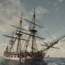
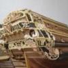
tlevine reacted to Jeronimo in LE BONHOMME RICHARD by Jeronimo - FINISHED
Hello,
capstan prepared for installation on the gun deck.
Karl
T e i l 42
-
tlevine reacted to Remcohe in HMS Kingfisher 1770 by Remcohe - 1/48 - English 14-Gun Sloop - POF
No can do John , but I can tell you it was a nice little project I can recommend to every one. Those shallow drawers are just great. Next to this I use Ikea's little boxes to store other tools and supply's unfortunately they don't sell this type any more, a real shame. I'm still looking for a better way to organize my sanding paper, keeping them in a big stack is not working...
So back to making bulkheads, I use wooden peg's under the stanchions to temporary fit and adjust until I'm getting a fit I like.
The cook's working space was not very big. Behind the riding bitt's there is another bulkhead drawn on my plan I thin I'll make a nice cupboard for the cook to store his pot's, pan's and other tools.
-
tlevine reacted to Dan Vadas in HMS Vulture 1776 by Dan Vadas - FINISHED - 1:48 scale - 16-gun Swan-class sloop from TFFM plans
Thank you Mark, John, Druxey and Pat. The puns are flying thick and fast today . Thanks also to all those who have been using the "Like" button.
Main Studding Sail Boom Irons
There are two pieces of ironwork attached to each main channel. One of these is an Eyestrap, into which a pin on the inboard end of the Main Studding Sail fits allowing it to swing out. The other (aft) one is a Gooseneck which holds the outboard end of the boom when it is stowed.
I made these from 1mm thick brass strip. Both pieces taper in width and thickness on the inboard ends. I drilled three holes in each piece for the "bolts", which are made from brass pins silver soldered to the straps and the heads filed square.
The gooseneck part was silver soldered to the arm, as it needed a very sharp bend which wasn't possible to do. I trimmed the brass nails to the thickness of the channel :
The pieces fitted after cleaning up and blackening :
Danny
-
tlevine reacted to robbl in HMS Blanche 1800 by robbl - 1/48 - POF - was HMS Euryalus 1803
Hi all
A little bit of progress internally. First, I added t-track and bolts to the building board so my gantry can be used for height measurment and clamping. Then, a new assistant supervisor was appointed.....
Retired Admiral the Lord Bob brings experience to the task.
Then, to learn about making decks and platforms, I decided to start with the aft magazine and platform, as it looked a lot simpler than the fore platorm. First I used the bulkheads I had made from Matai in the last progress post to construct the walls of the aft magazine.
And I also cut the aft platform beams from Totara, and checked their positioning for height along with the magazine.
I started with the idea of milling the mortices, but that took longer than cutting them with a scalpel and small chisels. This effort highlighted two things - I need smaller chisels and I need to cut away from the hand ... blood is on the underside of the beams.
At this stage I realised my potential for getting all the angles and measurements wrong while working inside the hull was immense, so made slots in a piece of offcut wood to allow me to construct the platform off ship.
This allowed me to line up the timbers and their mortices and hold everything nicely in place while I worked, so I ended up with this....
Which when placed back in the hull with the magazine looks like this ....
So I still have to do the knees, and until I do, the platform will not be fixed inside the hull. You might notice, in the close up of the top down image attachment below, the magazine has its floor planked (Rimu), next for it will be the internal bulkheads, lightroom fittings and doors. The "jig" for the platform worked so well, I plan on continuing that method for the orlop deck and fore platform, however I want to finish this aft area first.
oh, almost forgot, another "take-away lesson" from this was to avoid the use of blu-tack to test fit the beams in place ... it was difficult to get off afterwards.
Cheers
Rob
-
tlevine reacted to EdT in Young America 1853 by EdT - FINISHED - extreme clipper
Young America - extreme clipper 1853
Part 41 – Aft Half Frames 2
Now for the final hull frames.
The first picture shows two half frames being glued to opposite sides of the keelson using a different method of clamping than that used for the previous frames.
As the framing moves forward the frames become more full at the base. This makes the use of screw clamps increasingly awkward. For the remaining frames the feet were held in place for the toptimber pinning and then gluing using the method shown. Wood strips are pushed to the frame and held in place by the T-track clamps. This proved much easier and, as is shown in the picture, frames on either side could be installed concurrently.
The next picture shows a closer view and also a 1:72 figure – by special request.
In the next picture a frame is being pinned to the ribband at the top while held against the keelson at the base.
After pinning, the clamp is pulled back, glue is applied to the the joint and the clamp returned until the glue dries.
The pin-indexing method of assembling frames requires that all but the toptimbers are of the same siding, in this case 12”. The upper futtocks then need to be reduced in thickness after assembly, bevelling and removal of the patterns. In the next picture this is being done with a flat file.
These pieces are awkward to secure in a vise, so for this work they were pinned to a piece of Homasote board through the bolt holes.
In the next picture, the fairness of the external hull is being checked before installing the last half frame on the side.
This is also being done on the inside in the next picture.
The frames were pre-beveled to within to within roughly 1/64” of final breadth – to the outer side of the pattern lines inboard and outboard on each face. Where there are gaps of more than about 1/64” when checked as above, the offending frame was removed and reset. There were only a few of these and resetting their height brought them within range. Final sanding will finish the job.
In the next picture the last frame is being pinned to the ribband by bending over the end of the pin. The foot of the frame foot was then glued to the keelson.
Installation of this last frame was a big milestone. The last two pictures show the full hull after completing the framing.
There is no doubt that some of the toptimbers will need to be replaced later to precisely fair the upper rails. Hopefully the number will be few, but these small pieces are most subject to error when assembling the frames. They are indexed in assembly by only two pins and the pins are close together. One has already been removed below.
The hull is now ready for final fairing.
Ed
-
tlevine got a reaction from paulsutcliffe in HMS Atalanta 1775 by tlevine - FINISHED - 1:48 scale - from TFFM plans
My general approach for fabricating and installing the beam sets has been one complete set at a time. This worked well where there was no curvature of the hull but I had difficulty with the run of the outer carlings at the fore end of the upper deck and decided to change my approach as I neared the stern. I set out all of the beams and tack glued them in place. I then drew fair lines for the outer carlings. The deck beams were removed as I worked on them, only mortising the outer carlings. The carlings were then tack glued without gluing the beam. This continued until the last two beams. The transom knee abuts the for end of the transom and extends along the hull just past beam 20. It is set down on to the deck clamp and "bolted" to the frames and transom. The last two beams are mortised into the transom knee.
The pictures show the run of the lateral carlings. No finish shaping or sanding has been done yet. I broke off the port counter timbers (again!) and just stuck it back on so that area looks out of whack. I will probably have to remake it when it comes time to make the counter.
-
 tlevine got a reaction from WackoWolf in HMS Atalanta 1775 by tlevine - FINISHED - 1:48 scale - from TFFM plans
Druxey, suggestion well taken...and done. David it really isn't all that fragile except for this area and the stem. I have broken this off several times already and until now it was good enough because this is the side I intend to plank. So far the stem has been unscathed.
-
 tlevine got a reaction from Kevin in HMS Atalanta 1775 by tlevine - FINISHED - 1:48 scale - from TFFM plans
My general approach for fabricating and installing the beam sets has been one complete set at a time. This worked well where there was no curvature of the hull but I had difficulty with the run of the outer carlings at the fore end of the upper deck and decided to change my approach as I neared the stern. I set out all of the beams and tack glued them in place. I then drew fair lines for the outer carlings. The deck beams were removed as I worked on them, only mortising the outer carlings. The carlings were then tack glued without gluing the beam. This continued until the last two beams. The transom knee abuts the for end of the transom and extends along the hull just past beam 20. It is set down on to the deck clamp and "bolted" to the frames and transom. The last two beams are mortised into the transom knee.
The pictures show the run of the lateral carlings. No finish shaping or sanding has been done yet. I broke off the port counter timbers (again!) and just stuck it back on so that area looks out of whack. I will probably have to remake it when it comes time to make the counter.
-
 tlevine got a reaction from Elmer Cornish in HMS Atalanta 1775 by tlevine - FINISHED - 1:48 scale - from TFFM plans
My general approach for fabricating and installing the beam sets has been one complete set at a time. This worked well where there was no curvature of the hull but I had difficulty with the run of the outer carlings at the fore end of the upper deck and decided to change my approach as I neared the stern. I set out all of the beams and tack glued them in place. I then drew fair lines for the outer carlings. The deck beams were removed as I worked on them, only mortising the outer carlings. The carlings were then tack glued without gluing the beam. This continued until the last two beams. The transom knee abuts the for end of the transom and extends along the hull just past beam 20. It is set down on to the deck clamp and "bolted" to the frames and transom. The last two beams are mortised into the transom knee.
The pictures show the run of the lateral carlings. No finish shaping or sanding has been done yet. I broke off the port counter timbers (again!) and just stuck it back on so that area looks out of whack. I will probably have to remake it when it comes time to make the counter.
-
 tlevine got a reaction from Erebus and Terror in HMS Atalanta 1775 by tlevine - FINISHED - 1:48 scale - from TFFM plans
My general approach for fabricating and installing the beam sets has been one complete set at a time. This worked well where there was no curvature of the hull but I had difficulty with the run of the outer carlings at the fore end of the upper deck and decided to change my approach as I neared the stern. I set out all of the beams and tack glued them in place. I then drew fair lines for the outer carlings. The deck beams were removed as I worked on them, only mortising the outer carlings. The carlings were then tack glued without gluing the beam. This continued until the last two beams. The transom knee abuts the for end of the transom and extends along the hull just past beam 20. It is set down on to the deck clamp and "bolted" to the frames and transom. The last two beams are mortised into the transom knee.
The pictures show the run of the lateral carlings. No finish shaping or sanding has been done yet. I broke off the port counter timbers (again!) and just stuck it back on so that area looks out of whack. I will probably have to remake it when it comes time to make the counter.
-
 tlevine got a reaction from AnobiumPunctatum in HMS Atalanta 1775 by tlevine - FINISHED - 1:48 scale - from TFFM plans
My general approach for fabricating and installing the beam sets has been one complete set at a time. This worked well where there was no curvature of the hull but I had difficulty with the run of the outer carlings at the fore end of the upper deck and decided to change my approach as I neared the stern. I set out all of the beams and tack glued them in place. I then drew fair lines for the outer carlings. The deck beams were removed as I worked on them, only mortising the outer carlings. The carlings were then tack glued without gluing the beam. This continued until the last two beams. The transom knee abuts the for end of the transom and extends along the hull just past beam 20. It is set down on to the deck clamp and "bolted" to the frames and transom. The last two beams are mortised into the transom knee.
The pictures show the run of the lateral carlings. No finish shaping or sanding has been done yet. I broke off the port counter timbers (again!) and just stuck it back on so that area looks out of whack. I will probably have to remake it when it comes time to make the counter.
-
 tlevine got a reaction from cabrapente in HMS Atalanta 1775 by tlevine - FINISHED - 1:48 scale - from TFFM plans
My general approach for fabricating and installing the beam sets has been one complete set at a time. This worked well where there was no curvature of the hull but I had difficulty with the run of the outer carlings at the fore end of the upper deck and decided to change my approach as I neared the stern. I set out all of the beams and tack glued them in place. I then drew fair lines for the outer carlings. The deck beams were removed as I worked on them, only mortising the outer carlings. The carlings were then tack glued without gluing the beam. This continued until the last two beams. The transom knee abuts the for end of the transom and extends along the hull just past beam 20. It is set down on to the deck clamp and "bolted" to the frames and transom. The last two beams are mortised into the transom knee.
The pictures show the run of the lateral carlings. No finish shaping or sanding has been done yet. I broke off the port counter timbers (again!) and just stuck it back on so that area looks out of whack. I will probably have to remake it when it comes time to make the counter.
-
 tlevine got a reaction from avsjerome2003 in HMS Atalanta 1775 by tlevine - FINISHED - 1:48 scale - from TFFM plans
My general approach for fabricating and installing the beam sets has been one complete set at a time. This worked well where there was no curvature of the hull but I had difficulty with the run of the outer carlings at the fore end of the upper deck and decided to change my approach as I neared the stern. I set out all of the beams and tack glued them in place. I then drew fair lines for the outer carlings. The deck beams were removed as I worked on them, only mortising the outer carlings. The carlings were then tack glued without gluing the beam. This continued until the last two beams. The transom knee abuts the for end of the transom and extends along the hull just past beam 20. It is set down on to the deck clamp and "bolted" to the frames and transom. The last two beams are mortised into the transom knee.
The pictures show the run of the lateral carlings. No finish shaping or sanding has been done yet. I broke off the port counter timbers (again!) and just stuck it back on so that area looks out of whack. I will probably have to remake it when it comes time to make the counter.
-
 tlevine got a reaction from harvey1847 in HMS Atalanta 1775 by tlevine - FINISHED - 1:48 scale - from TFFM plans
My general approach for fabricating and installing the beam sets has been one complete set at a time. This worked well where there was no curvature of the hull but I had difficulty with the run of the outer carlings at the fore end of the upper deck and decided to change my approach as I neared the stern. I set out all of the beams and tack glued them in place. I then drew fair lines for the outer carlings. The deck beams were removed as I worked on them, only mortising the outer carlings. The carlings were then tack glued without gluing the beam. This continued until the last two beams. The transom knee abuts the for end of the transom and extends along the hull just past beam 20. It is set down on to the deck clamp and "bolted" to the frames and transom. The last two beams are mortised into the transom knee.
The pictures show the run of the lateral carlings. No finish shaping or sanding has been done yet. I broke off the port counter timbers (again!) and just stuck it back on so that area looks out of whack. I will probably have to remake it when it comes time to make the counter.
-
 tlevine got a reaction from SailorGreg in HMS Atalanta 1775 by tlevine - FINISHED - 1:48 scale - from TFFM plans
My general approach for fabricating and installing the beam sets has been one complete set at a time. This worked well where there was no curvature of the hull but I had difficulty with the run of the outer carlings at the fore end of the upper deck and decided to change my approach as I neared the stern. I set out all of the beams and tack glued them in place. I then drew fair lines for the outer carlings. The deck beams were removed as I worked on them, only mortising the outer carlings. The carlings were then tack glued without gluing the beam. This continued until the last two beams. The transom knee abuts the for end of the transom and extends along the hull just past beam 20. It is set down on to the deck clamp and "bolted" to the frames and transom. The last two beams are mortised into the transom knee.
The pictures show the run of the lateral carlings. No finish shaping or sanding has been done yet. I broke off the port counter timbers (again!) and just stuck it back on so that area looks out of whack. I will probably have to remake it when it comes time to make the counter.
-
 tlevine got a reaction from Paryzek in HMS Atalanta 1775 by tlevine - FINISHED - 1:48 scale - from TFFM plans
My general approach for fabricating and installing the beam sets has been one complete set at a time. This worked well where there was no curvature of the hull but I had difficulty with the run of the outer carlings at the fore end of the upper deck and decided to change my approach as I neared the stern. I set out all of the beams and tack glued them in place. I then drew fair lines for the outer carlings. The deck beams were removed as I worked on them, only mortising the outer carlings. The carlings were then tack glued without gluing the beam. This continued until the last two beams. The transom knee abuts the for end of the transom and extends along the hull just past beam 20. It is set down on to the deck clamp and "bolted" to the frames and transom. The last two beams are mortised into the transom knee.
The pictures show the run of the lateral carlings. No finish shaping or sanding has been done yet. I broke off the port counter timbers (again!) and just stuck it back on so that area looks out of whack. I will probably have to remake it when it comes time to make the counter.
-
 tlevine got a reaction from gjdale in HMS Atalanta 1775 by tlevine - FINISHED - 1:48 scale - from TFFM plans
My general approach for fabricating and installing the beam sets has been one complete set at a time. This worked well where there was no curvature of the hull but I had difficulty with the run of the outer carlings at the fore end of the upper deck and decided to change my approach as I neared the stern. I set out all of the beams and tack glued them in place. I then drew fair lines for the outer carlings. The deck beams were removed as I worked on them, only mortising the outer carlings. The carlings were then tack glued without gluing the beam. This continued until the last two beams. The transom knee abuts the for end of the transom and extends along the hull just past beam 20. It is set down on to the deck clamp and "bolted" to the frames and transom. The last two beams are mortised into the transom knee.
The pictures show the run of the lateral carlings. No finish shaping or sanding has been done yet. I broke off the port counter timbers (again!) and just stuck it back on so that area looks out of whack. I will probably have to remake it when it comes time to make the counter.
-
tlevine reacted to Trussben in HMS Pegasus 1776 by Trussben - 1:48 - Swan-class sloop based on TFFM
Small update,
Stem Pieces, Lower and Upper Apron and Fore Deadwood completed and glued to the keel.
I used some bamboo treenails and a #65 bit to add some heavy reinforcement to these pieces
as you can see.
Now I need to do the tapering up/down from 14" at top to 10" and the keel.
I have started making the aft deadwood pieces from 15" stock.
ben
-
tlevine got a reaction from Elmer Cornish in HMS Atalanta 1775 by tlevine - FINISHED - 1:48 scale - from TFFM plans
John and Elia, thank you for your kind comments. Thanks for all the Likes as well. A little more has been accomplished this weekend. I have applied the finish to the pantry. Beam set 14 has been installed and beam set 15 is in progess. The middle carlings are larger to support the capstain partner. Unlike the carlings for the mast partners, this piece is installed like a regular carling (ie from on top) rather than under the beam.
-
tlevine got a reaction from Elmer Cornish in HMS Atalanta 1775 by tlevine - FINISHED - 1:48 scale - from TFFM plans
Work progresses slowly on the upper deck framing. No pics this week. The next significant structure to construct is the capstan step. In TFFM this is shown as a roughly rectangular block of wood inserted between the beams and its supporting carlings. On the Atalanta plans there is a ovate structure instead. This would seem to have much less strength than the one suggested by David. I am looking for some help on this one. Is the structure shown on the plan correct? Or is this seated on top of a rectangular step?