

tlevine
-
Posts
1,938 -
Joined
-
Last visited
Reputation Activity
-

 tlevine got a reaction from modeller_masa in NRG Rigging Project by tlevine
It is time to start rigging the mast. Some lines are served with an additional layer of line wrapped around them to protect them wherever they would be at risk of damage from rubbing. On this model, the pendant of tackles, the foremost shroud, the other shrouds above the catharpins and the jeer block strop are served. Because this is a cross-section, the main and back stays will not be installed but they would also be served. Standing rigging is protected from water damage with a tar-like compound. This resulted in a dark brown appearance to the lines. The running rigging was not protected and so was a natural hemp color. On this model, the burton pendants and shrouds are standing rigging; everything else is running rigging
Rope sizes are calculated from the diameter of the mast. The kit contains a table with the dimensions for the various ropes, based on the diameter of the mast. To measure the diameter of the line, I wrap it around a dowel twenty times, measure the width of the wrapping and divide by twenty. This is much more accurate than trying to measure an individual line. The first rope to go over the masthead is the pendant of tackles. On the topmast, this line is referred to as the burton pendant. This rope is completely served, and has a thimble on one end. The other end is spliced to its opposite, resulting in the rope in the diagram below. Where the red and blue lines meet are splices. The pendants extend to approximately two feet below the hounds. They were used with a tackle to raise and lower heavy weights.
To properly rig a model there is no substitute for the appearance of a served line. I use 6-0 fly tying thread, which can be purchased at a sporting goods store or online. I start by running thread, from left to right in this case, into the depression between the rope strands (worming), smoothing its surface (the yellow areas seen in the drawing below. Then I serve the rope from right to left.
I find it easier to serve short segments of rope, such as this, on the same piece of rope and then cut them apart. I served the rope, leaving approximately six inches of serving thread for the splices (red circles).
Then I made a diagonal cut, following the lay of the rope ¼” away from the end of the serving. The unserved line was held against the other line where the splice would go and I wrapped the two lines with the left-over serving thread “splicing” them together. I continued the wrapping a few more twists to smooth out the transition and tied it off. A tiny bit of dilute glue held everything together. The pendant was put over the mast head and onto the bolsters. It was marked on each leg, two feet below the hounds and removed from the mast. I used blackened 1/16” ID brass tubing for my thimbles. The mark was placed on the side of the thimble and the pendant was wrapped around it. For simplicity I used a simple seizing to secure the thimble and put it back on the mast.
-

 tlevine got a reaction from robert952 in NRG Rigging Project by tlevine
It is time to start rigging the mast. Some lines are served with an additional layer of line wrapped around them to protect them wherever they would be at risk of damage from rubbing. On this model, the pendant of tackles, the foremost shroud, the other shrouds above the catharpins and the jeer block strop are served. Because this is a cross-section, the main and back stays will not be installed but they would also be served. Standing rigging is protected from water damage with a tar-like compound. This resulted in a dark brown appearance to the lines. The running rigging was not protected and so was a natural hemp color. On this model, the burton pendants and shrouds are standing rigging; everything else is running rigging
Rope sizes are calculated from the diameter of the mast. The kit contains a table with the dimensions for the various ropes, based on the diameter of the mast. To measure the diameter of the line, I wrap it around a dowel twenty times, measure the width of the wrapping and divide by twenty. This is much more accurate than trying to measure an individual line. The first rope to go over the masthead is the pendant of tackles. On the topmast, this line is referred to as the burton pendant. This rope is completely served, and has a thimble on one end. The other end is spliced to its opposite, resulting in the rope in the diagram below. Where the red and blue lines meet are splices. The pendants extend to approximately two feet below the hounds. They were used with a tackle to raise and lower heavy weights.
To properly rig a model there is no substitute for the appearance of a served line. I use 6-0 fly tying thread, which can be purchased at a sporting goods store or online. I start by running thread, from left to right in this case, into the depression between the rope strands (worming), smoothing its surface (the yellow areas seen in the drawing below. Then I serve the rope from right to left.
I find it easier to serve short segments of rope, such as this, on the same piece of rope and then cut them apart. I served the rope, leaving approximately six inches of serving thread for the splices (red circles).
Then I made a diagonal cut, following the lay of the rope ¼” away from the end of the serving. The unserved line was held against the other line where the splice would go and I wrapped the two lines with the left-over serving thread “splicing” them together. I continued the wrapping a few more twists to smooth out the transition and tied it off. A tiny bit of dilute glue held everything together. The pendant was put over the mast head and onto the bolsters. It was marked on each leg, two feet below the hounds and removed from the mast. I used blackened 1/16” ID brass tubing for my thimbles. The mark was placed on the side of the thimble and the pendant was wrapped around it. For simplicity I used a simple seizing to secure the thimble and put it back on the mast.
-
 tlevine got a reaction from JeffT in NRG Rigging Project by tlevine
It is time to start rigging the mast. Some lines are served with an additional layer of line wrapped around them to protect them wherever they would be at risk of damage from rubbing. On this model, the pendant of tackles, the foremost shroud, the other shrouds above the catharpins and the jeer block strop are served. Because this is a cross-section, the main and back stays will not be installed but they would also be served. Standing rigging is protected from water damage with a tar-like compound. This resulted in a dark brown appearance to the lines. The running rigging was not protected and so was a natural hemp color. On this model, the burton pendants and shrouds are standing rigging; everything else is running rigging
Rope sizes are calculated from the diameter of the mast. The kit contains a table with the dimensions for the various ropes, based on the diameter of the mast. To measure the diameter of the line, I wrap it around a dowel twenty times, measure the width of the wrapping and divide by twenty. This is much more accurate than trying to measure an individual line. The first rope to go over the masthead is the pendant of tackles. On the topmast, this line is referred to as the burton pendant. This rope is completely served, and has a thimble on one end. The other end is spliced to its opposite, resulting in the rope in the diagram below. Where the red and blue lines meet are splices. The pendants extend to approximately two feet below the hounds. They were used with a tackle to raise and lower heavy weights.
To properly rig a model there is no substitute for the appearance of a served line. I use 6-0 fly tying thread, which can be purchased at a sporting goods store or online. I start by running thread, from left to right in this case, into the depression between the rope strands (worming), smoothing its surface (the yellow areas seen in the drawing below. Then I serve the rope from right to left.
I find it easier to serve short segments of rope, such as this, on the same piece of rope and then cut them apart. I served the rope, leaving approximately six inches of serving thread for the splices (red circles).
Then I made a diagonal cut, following the lay of the rope ¼” away from the end of the serving. The unserved line was held against the other line where the splice would go and I wrapped the two lines with the left-over serving thread “splicing” them together. I continued the wrapping a few more twists to smooth out the transition and tied it off. A tiny bit of dilute glue held everything together. The pendant was put over the mast head and onto the bolsters. It was marked on each leg, two feet below the hounds and removed from the mast. I used blackened 1/16” ID brass tubing for my thimbles. The mark was placed on the side of the thimble and the pendant was wrapped around it. For simplicity I used a simple seizing to secure the thimble and put it back on the mast.
-
 tlevine got a reaction from BenD in NRG Rigging Project by tlevine
It is time to start rigging the mast. Some lines are served with an additional layer of line wrapped around them to protect them wherever they would be at risk of damage from rubbing. On this model, the pendant of tackles, the foremost shroud, the other shrouds above the catharpins and the jeer block strop are served. Because this is a cross-section, the main and back stays will not be installed but they would also be served. Standing rigging is protected from water damage with a tar-like compound. This resulted in a dark brown appearance to the lines. The running rigging was not protected and so was a natural hemp color. On this model, the burton pendants and shrouds are standing rigging; everything else is running rigging
Rope sizes are calculated from the diameter of the mast. The kit contains a table with the dimensions for the various ropes, based on the diameter of the mast. To measure the diameter of the line, I wrap it around a dowel twenty times, measure the width of the wrapping and divide by twenty. This is much more accurate than trying to measure an individual line. The first rope to go over the masthead is the pendant of tackles. On the topmast, this line is referred to as the burton pendant. This rope is completely served, and has a thimble on one end. The other end is spliced to its opposite, resulting in the rope in the diagram below. Where the red and blue lines meet are splices. The pendants extend to approximately two feet below the hounds. They were used with a tackle to raise and lower heavy weights.
To properly rig a model there is no substitute for the appearance of a served line. I use 6-0 fly tying thread, which can be purchased at a sporting goods store or online. I start by running thread, from left to right in this case, into the depression between the rope strands (worming), smoothing its surface (the yellow areas seen in the drawing below. Then I serve the rope from right to left.
I find it easier to serve short segments of rope, such as this, on the same piece of rope and then cut them apart. I served the rope, leaving approximately six inches of serving thread for the splices (red circles).
Then I made a diagonal cut, following the lay of the rope ¼” away from the end of the serving. The unserved line was held against the other line where the splice would go and I wrapped the two lines with the left-over serving thread “splicing” them together. I continued the wrapping a few more twists to smooth out the transition and tied it off. A tiny bit of dilute glue held everything together. The pendant was put over the mast head and onto the bolsters. It was marked on each leg, two feet below the hounds and removed from the mast. I used blackened 1/16” ID brass tubing for my thimbles. The mark was placed on the side of the thimble and the pendant was wrapped around it. For simplicity I used a simple seizing to secure the thimble and put it back on the mast.
-
.jpg.d84ec4dad1d7791e855dca06210ab6f3.thumb.jpg.f45209242e851d4409eca1a09293165b.jpg) tlevine got a reaction from hollowneck in NRG Rigging Project by tlevine
tlevine got a reaction from hollowneck in NRG Rigging Project by tlevine
It is time to start rigging the mast. Some lines are served with an additional layer of line wrapped around them to protect them wherever they would be at risk of damage from rubbing. On this model, the pendant of tackles, the foremost shroud, the other shrouds above the catharpins and the jeer block strop are served. Because this is a cross-section, the main and back stays will not be installed but they would also be served. Standing rigging is protected from water damage with a tar-like compound. This resulted in a dark brown appearance to the lines. The running rigging was not protected and so was a natural hemp color. On this model, the burton pendants and shrouds are standing rigging; everything else is running rigging
Rope sizes are calculated from the diameter of the mast. The kit contains a table with the dimensions for the various ropes, based on the diameter of the mast. To measure the diameter of the line, I wrap it around a dowel twenty times, measure the width of the wrapping and divide by twenty. This is much more accurate than trying to measure an individual line. The first rope to go over the masthead is the pendant of tackles. On the topmast, this line is referred to as the burton pendant. This rope is completely served, and has a thimble on one end. The other end is spliced to its opposite, resulting in the rope in the diagram below. Where the red and blue lines meet are splices. The pendants extend to approximately two feet below the hounds. They were used with a tackle to raise and lower heavy weights.
To properly rig a model there is no substitute for the appearance of a served line. I use 6-0 fly tying thread, which can be purchased at a sporting goods store or online. I start by running thread, from left to right in this case, into the depression between the rope strands (worming), smoothing its surface (the yellow areas seen in the drawing below. Then I serve the rope from right to left.
I find it easier to serve short segments of rope, such as this, on the same piece of rope and then cut them apart. I served the rope, leaving approximately six inches of serving thread for the splices (red circles).
Then I made a diagonal cut, following the lay of the rope ¼” away from the end of the serving. The unserved line was held against the other line where the splice would go and I wrapped the two lines with the left-over serving thread “splicing” them together. I continued the wrapping a few more twists to smooth out the transition and tied it off. A tiny bit of dilute glue held everything together. The pendant was put over the mast head and onto the bolsters. It was marked on each leg, two feet below the hounds and removed from the mast. I used blackened 1/16” ID brass tubing for my thimbles. The mark was placed on the side of the thimble and the pendant was wrapped around it. For simplicity I used a simple seizing to secure the thimble and put it back on the mast.
-
tlevine got a reaction from hollowneck in NRG Rigging Project by tlevine
Everything depended on the size and type of ship. This little ship only had a lower mast and topmast.
-
tlevine got a reaction from hollowneck in NRG Rigging Project by tlevine
Most kits come with deadeyes and partially completed chains. Usually, the upper link (the link that goes around the deadeye) is pre-formed, with the bottom cut for insertion of the deadeye. Wire is provided for the builder to form the other two links but the entire assembly has very little strength and the cut ends of wire are ugly. The only way to make this assembly stronger and better looking is to solder the links closed. I prefer silver soldering, even though regular soldering will give sufficient strength. The benefit of silver soldering is that the metal is fused together rather than connected by a dissimilar metal, tin. This makes it easier to bend the part without worrying about the solder joint breaking. The downside is that there is a learning curve and the tools are more expensive. Silver solder also blackens well. There are also low melting point silver bearing solders (Tix) which can be blackened.
The measurements for all the parts of a British warship were determined by the Admiralty. There are reference books that contain this information such as Steel’s Tables. An easily read version of the tables is sold in the NRG store. The main mast diameter is given on the plans as 18”. Using the information from the tables, I determined that the main stay is 9” and the shrouds are 5.5”. Lines are measured by their circumference. The diameter of the deadeye is 1.5 times the size of the shroud or stay it is attached to, in this case 8 ¼”. A spreadsheet comes in handy in determining all the measurements.
Let me start by saying that my metal work has a bit to be desired. The chains are made from 1 ¼” wire, which is 22 gauge. I temper the wire by drawing it through a gas flame until it glows red. This makes the wire more malleable and removes any factory applied coating.
The deadeye chain is the same length for all the deadeyes. Make one and use it as a template for the others. I wrapped wire around the deadeye, leaving long tails, and inserted this into the slot in the channel. The tails were cut long enough to be able form the loop below the channel. I removed the deadeye and applied a finish.
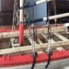
The lower links are all the same length. From the plans I knew that the toe of the lower link is bolted 5” below the top of the wale and that its overall length was 9”. Two T-pins were inserted into the soldering board and the wire was wrapped around them, with the cut ends on the side. The middle link is different for every shroud because each is at a different angle to the mast as seen in the two pictures below. The link becomes longer with greater angulation of the shroud. You can see the difference in the shroud angles and how this would affect the length of the middle link.
To determine the angle of the chains, I put masking tape on the hull above and below the channel. A loop of rope was placed over the mast head and inserted through a slot in the channel. The angles made by the shroud were transferred to the tape. I dimpled the wale where the toe of the lower link and the lower preventer chain bolts will be located and removed the tape.
A hole was drilled through the wale where the toe of the lower link would later be bolted. The lower link and deadeye were temporarily installed. The length of the middle chains was determined by trial and error. With the deadeye and lower link in place, I formed the middle link from rope the same thickness as the wire and transferred those lengths to wire. I formed the middle link and soldered it closed, keeping the joint on one of the long sides. Then I inserted the lower link through the middle link and soldered it.
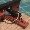
A T-pin was pushed into the soldering board and used to form the lower link toe. The lower link is also bent at the toe, allowing it to lay flat against the wale.
Finally, the wire for the upper link was passed through the middle link and soldered. The deadeye was inserted into the loop and the wire was crimped around it to fit into the channel slot, placing the solder joint in the slot camouflaged it.
And here are the ten chains, ready for blackening. The blackening chemical did not damage the wood deadeyes.
After blackening, the chains were installed. I have a piece of wire temporarily holding the lower link to the wale.
The preventer plate prevents the bolt securing the lower link from going all the way through the toe. It was made from square bar stock that was forged to the correct shape. Mine are made from sheet brass, cut and filed to the correct shape. Just like the middle links, they varied in length. The top of the plate makes a step over the bottom of the lower link toe to cover it. To determine the distance between the bolt holes on the plate, I measured the distance between the toe bolt and the previously marked lower preventer plate bolt and added the diameter of the wire the link was made from. The sequence is shown in the drawing below. After they were finished, they were blackened and installed.
To hold the upper links in the channels, a strip of molding was placed over them. Next up, the rigging begins.
-
 tlevine got a reaction from Thukydides in NRG Rigging Project by tlevine
It is time to start rigging the mast. Some lines are served with an additional layer of line wrapped around them to protect them wherever they would be at risk of damage from rubbing. On this model, the pendant of tackles, the foremost shroud, the other shrouds above the catharpins and the jeer block strop are served. Because this is a cross-section, the main and back stays will not be installed but they would also be served. Standing rigging is protected from water damage with a tar-like compound. This resulted in a dark brown appearance to the lines. The running rigging was not protected and so was a natural hemp color. On this model, the burton pendants and shrouds are standing rigging; everything else is running rigging
Rope sizes are calculated from the diameter of the mast. The kit contains a table with the dimensions for the various ropes, based on the diameter of the mast. To measure the diameter of the line, I wrap it around a dowel twenty times, measure the width of the wrapping and divide by twenty. This is much more accurate than trying to measure an individual line. The first rope to go over the masthead is the pendant of tackles. On the topmast, this line is referred to as the burton pendant. This rope is completely served, and has a thimble on one end. The other end is spliced to its opposite, resulting in the rope in the diagram below. Where the red and blue lines meet are splices. The pendants extend to approximately two feet below the hounds. They were used with a tackle to raise and lower heavy weights.
To properly rig a model there is no substitute for the appearance of a served line. I use 6-0 fly tying thread, which can be purchased at a sporting goods store or online. I start by running thread, from left to right in this case, into the depression between the rope strands (worming), smoothing its surface (the yellow areas seen in the drawing below. Then I serve the rope from right to left.
I find it easier to serve short segments of rope, such as this, on the same piece of rope and then cut them apart. I served the rope, leaving approximately six inches of serving thread for the splices (red circles).
Then I made a diagonal cut, following the lay of the rope ¼” away from the end of the serving. The unserved line was held against the other line where the splice would go and I wrapped the two lines with the left-over serving thread “splicing” them together. I continued the wrapping a few more twists to smooth out the transition and tied it off. A tiny bit of dilute glue held everything together. The pendant was put over the mast head and onto the bolsters. It was marked on each leg, two feet below the hounds and removed from the mast. I used blackened 1/16” ID brass tubing for my thimbles. The mark was placed on the side of the thimble and the pendant was wrapped around it. For simplicity I used a simple seizing to secure the thimble and put it back on the mast.
-
 tlevine got a reaction from dvm27 in NRG Rigging Project by tlevine
It is time to start rigging the mast. Some lines are served with an additional layer of line wrapped around them to protect them wherever they would be at risk of damage from rubbing. On this model, the pendant of tackles, the foremost shroud, the other shrouds above the catharpins and the jeer block strop are served. Because this is a cross-section, the main and back stays will not be installed but they would also be served. Standing rigging is protected from water damage with a tar-like compound. This resulted in a dark brown appearance to the lines. The running rigging was not protected and so was a natural hemp color. On this model, the burton pendants and shrouds are standing rigging; everything else is running rigging
Rope sizes are calculated from the diameter of the mast. The kit contains a table with the dimensions for the various ropes, based on the diameter of the mast. To measure the diameter of the line, I wrap it around a dowel twenty times, measure the width of the wrapping and divide by twenty. This is much more accurate than trying to measure an individual line. The first rope to go over the masthead is the pendant of tackles. On the topmast, this line is referred to as the burton pendant. This rope is completely served, and has a thimble on one end. The other end is spliced to its opposite, resulting in the rope in the diagram below. Where the red and blue lines meet are splices. The pendants extend to approximately two feet below the hounds. They were used with a tackle to raise and lower heavy weights.
To properly rig a model there is no substitute for the appearance of a served line. I use 6-0 fly tying thread, which can be purchased at a sporting goods store or online. I start by running thread, from left to right in this case, into the depression between the rope strands (worming), smoothing its surface (the yellow areas seen in the drawing below. Then I serve the rope from right to left.
I find it easier to serve short segments of rope, such as this, on the same piece of rope and then cut them apart. I served the rope, leaving approximately six inches of serving thread for the splices (red circles).
Then I made a diagonal cut, following the lay of the rope ¼” away from the end of the serving. The unserved line was held against the other line where the splice would go and I wrapped the two lines with the left-over serving thread “splicing” them together. I continued the wrapping a few more twists to smooth out the transition and tied it off. A tiny bit of dilute glue held everything together. The pendant was put over the mast head and onto the bolsters. It was marked on each leg, two feet below the hounds and removed from the mast. I used blackened 1/16” ID brass tubing for my thimbles. The mark was placed on the side of the thimble and the pendant was wrapped around it. For simplicity I used a simple seizing to secure the thimble and put it back on the mast.
-
 tlevine got a reaction from CraigVT in NRG Rigging Project by tlevine
It is time to start rigging the mast. Some lines are served with an additional layer of line wrapped around them to protect them wherever they would be at risk of damage from rubbing. On this model, the pendant of tackles, the foremost shroud, the other shrouds above the catharpins and the jeer block strop are served. Because this is a cross-section, the main and back stays will not be installed but they would also be served. Standing rigging is protected from water damage with a tar-like compound. This resulted in a dark brown appearance to the lines. The running rigging was not protected and so was a natural hemp color. On this model, the burton pendants and shrouds are standing rigging; everything else is running rigging
Rope sizes are calculated from the diameter of the mast. The kit contains a table with the dimensions for the various ropes, based on the diameter of the mast. To measure the diameter of the line, I wrap it around a dowel twenty times, measure the width of the wrapping and divide by twenty. This is much more accurate than trying to measure an individual line. The first rope to go over the masthead is the pendant of tackles. On the topmast, this line is referred to as the burton pendant. This rope is completely served, and has a thimble on one end. The other end is spliced to its opposite, resulting in the rope in the diagram below. Where the red and blue lines meet are splices. The pendants extend to approximately two feet below the hounds. They were used with a tackle to raise and lower heavy weights.
To properly rig a model there is no substitute for the appearance of a served line. I use 6-0 fly tying thread, which can be purchased at a sporting goods store or online. I start by running thread, from left to right in this case, into the depression between the rope strands (worming), smoothing its surface (the yellow areas seen in the drawing below. Then I serve the rope from right to left.
I find it easier to serve short segments of rope, such as this, on the same piece of rope and then cut them apart. I served the rope, leaving approximately six inches of serving thread for the splices (red circles).
Then I made a diagonal cut, following the lay of the rope ¼” away from the end of the serving. The unserved line was held against the other line where the splice would go and I wrapped the two lines with the left-over serving thread “splicing” them together. I continued the wrapping a few more twists to smooth out the transition and tied it off. A tiny bit of dilute glue held everything together. The pendant was put over the mast head and onto the bolsters. It was marked on each leg, two feet below the hounds and removed from the mast. I used blackened 1/16” ID brass tubing for my thimbles. The mark was placed on the side of the thimble and the pendant was wrapped around it. For simplicity I used a simple seizing to secure the thimble and put it back on the mast.
-
 tlevine got a reaction from JacquesCousteau in NRG Rigging Project by tlevine
It is time to start rigging the mast. Some lines are served with an additional layer of line wrapped around them to protect them wherever they would be at risk of damage from rubbing. On this model, the pendant of tackles, the foremost shroud, the other shrouds above the catharpins and the jeer block strop are served. Because this is a cross-section, the main and back stays will not be installed but they would also be served. Standing rigging is protected from water damage with a tar-like compound. This resulted in a dark brown appearance to the lines. The running rigging was not protected and so was a natural hemp color. On this model, the burton pendants and shrouds are standing rigging; everything else is running rigging
Rope sizes are calculated from the diameter of the mast. The kit contains a table with the dimensions for the various ropes, based on the diameter of the mast. To measure the diameter of the line, I wrap it around a dowel twenty times, measure the width of the wrapping and divide by twenty. This is much more accurate than trying to measure an individual line. The first rope to go over the masthead is the pendant of tackles. On the topmast, this line is referred to as the burton pendant. This rope is completely served, and has a thimble on one end. The other end is spliced to its opposite, resulting in the rope in the diagram below. Where the red and blue lines meet are splices. The pendants extend to approximately two feet below the hounds. They were used with a tackle to raise and lower heavy weights.
To properly rig a model there is no substitute for the appearance of a served line. I use 6-0 fly tying thread, which can be purchased at a sporting goods store or online. I start by running thread, from left to right in this case, into the depression between the rope strands (worming), smoothing its surface (the yellow areas seen in the drawing below. Then I serve the rope from right to left.
I find it easier to serve short segments of rope, such as this, on the same piece of rope and then cut them apart. I served the rope, leaving approximately six inches of serving thread for the splices (red circles).
Then I made a diagonal cut, following the lay of the rope ¼” away from the end of the serving. The unserved line was held against the other line where the splice would go and I wrapped the two lines with the left-over serving thread “splicing” them together. I continued the wrapping a few more twists to smooth out the transition and tied it off. A tiny bit of dilute glue held everything together. The pendant was put over the mast head and onto the bolsters. It was marked on each leg, two feet below the hounds and removed from the mast. I used blackened 1/16” ID brass tubing for my thimbles. The mark was placed on the side of the thimble and the pendant was wrapped around it. For simplicity I used a simple seizing to secure the thimble and put it back on the mast.
-
 tlevine got a reaction from gjdale in NRG Rigging Project by tlevine
It is time to start rigging the mast. Some lines are served with an additional layer of line wrapped around them to protect them wherever they would be at risk of damage from rubbing. On this model, the pendant of tackles, the foremost shroud, the other shrouds above the catharpins and the jeer block strop are served. Because this is a cross-section, the main and back stays will not be installed but they would also be served. Standing rigging is protected from water damage with a tar-like compound. This resulted in a dark brown appearance to the lines. The running rigging was not protected and so was a natural hemp color. On this model, the burton pendants and shrouds are standing rigging; everything else is running rigging
Rope sizes are calculated from the diameter of the mast. The kit contains a table with the dimensions for the various ropes, based on the diameter of the mast. To measure the diameter of the line, I wrap it around a dowel twenty times, measure the width of the wrapping and divide by twenty. This is much more accurate than trying to measure an individual line. The first rope to go over the masthead is the pendant of tackles. On the topmast, this line is referred to as the burton pendant. This rope is completely served, and has a thimble on one end. The other end is spliced to its opposite, resulting in the rope in the diagram below. Where the red and blue lines meet are splices. The pendants extend to approximately two feet below the hounds. They were used with a tackle to raise and lower heavy weights.
To properly rig a model there is no substitute for the appearance of a served line. I use 6-0 fly tying thread, which can be purchased at a sporting goods store or online. I start by running thread, from left to right in this case, into the depression between the rope strands (worming), smoothing its surface (the yellow areas seen in the drawing below. Then I serve the rope from right to left.
I find it easier to serve short segments of rope, such as this, on the same piece of rope and then cut them apart. I served the rope, leaving approximately six inches of serving thread for the splices (red circles).
Then I made a diagonal cut, following the lay of the rope ¼” away from the end of the serving. The unserved line was held against the other line where the splice would go and I wrapped the two lines with the left-over serving thread “splicing” them together. I continued the wrapping a few more twists to smooth out the transition and tied it off. A tiny bit of dilute glue held everything together. The pendant was put over the mast head and onto the bolsters. It was marked on each leg, two feet below the hounds and removed from the mast. I used blackened 1/16” ID brass tubing for my thimbles. The mark was placed on the side of the thimble and the pendant was wrapped around it. For simplicity I used a simple seizing to secure the thimble and put it back on the mast.
-
 tlevine got a reaction from Seventynet in NRG Rigging Project by tlevine
Most kits come with deadeyes and partially completed chains. Usually, the upper link (the link that goes around the deadeye) is pre-formed, with the bottom cut for insertion of the deadeye. Wire is provided for the builder to form the other two links but the entire assembly has very little strength and the cut ends of wire are ugly. The only way to make this assembly stronger and better looking is to solder the links closed. I prefer silver soldering, even though regular soldering will give sufficient strength. The benefit of silver soldering is that the metal is fused together rather than connected by a dissimilar metal, tin. This makes it easier to bend the part without worrying about the solder joint breaking. The downside is that there is a learning curve and the tools are more expensive. Silver solder also blackens well. There are also low melting point silver bearing solders (Tix) which can be blackened.
The measurements for all the parts of a British warship were determined by the Admiralty. There are reference books that contain this information such as Steel’s Tables. An easily read version of the tables is sold in the NRG store. The main mast diameter is given on the plans as 18”. Using the information from the tables, I determined that the main stay is 9” and the shrouds are 5.5”. Lines are measured by their circumference. The diameter of the deadeye is 1.5 times the size of the shroud or stay it is attached to, in this case 8 ¼”. A spreadsheet comes in handy in determining all the measurements.
Let me start by saying that my metal work has a bit to be desired. The chains are made from 1 ¼” wire, which is 22 gauge. I temper the wire by drawing it through a gas flame until it glows red. This makes the wire more malleable and removes any factory applied coating.
The deadeye chain is the same length for all the deadeyes. Make one and use it as a template for the others. I wrapped wire around the deadeye, leaving long tails, and inserted this into the slot in the channel. The tails were cut long enough to be able form the loop below the channel. I removed the deadeye and applied a finish.
The lower links are all the same length. From the plans I knew that the toe of the lower link is bolted 5” below the top of the wale and that its overall length was 9”. Two T-pins were inserted into the soldering board and the wire was wrapped around them, with the cut ends on the side. The middle link is different for every shroud because each is at a different angle to the mast as seen in the two pictures below. The link becomes longer with greater angulation of the shroud. You can see the difference in the shroud angles and how this would affect the length of the middle link.
To determine the angle of the chains, I put masking tape on the hull above and below the channel. A loop of rope was placed over the mast head and inserted through a slot in the channel. The angles made by the shroud were transferred to the tape. I dimpled the wale where the toe of the lower link and the lower preventer chain bolts will be located and removed the tape.
A hole was drilled through the wale where the toe of the lower link would later be bolted. The lower link and deadeye were temporarily installed. The length of the middle chains was determined by trial and error. With the deadeye and lower link in place, I formed the middle link from rope the same thickness as the wire and transferred those lengths to wire. I formed the middle link and soldered it closed, keeping the joint on one of the long sides. Then I inserted the lower link through the middle link and soldered it.
A T-pin was pushed into the soldering board and used to form the lower link toe. The lower link is also bent at the toe, allowing it to lay flat against the wale.
Finally, the wire for the upper link was passed through the middle link and soldered. The deadeye was inserted into the loop and the wire was crimped around it to fit into the channel slot, placing the solder joint in the slot camouflaged it.
And here are the ten chains, ready for blackening. The blackening chemical did not damage the wood deadeyes.
After blackening, the chains were installed. I have a piece of wire temporarily holding the lower link to the wale.
The preventer plate prevents the bolt securing the lower link from going all the way through the toe. It was made from square bar stock that was forged to the correct shape. Mine are made from sheet brass, cut and filed to the correct shape. Just like the middle links, they varied in length. The top of the plate makes a step over the bottom of the lower link toe to cover it. To determine the distance between the bolt holes on the plate, I measured the distance between the toe bolt and the previously marked lower preventer plate bolt and added the diameter of the wire the link was made from. The sequence is shown in the drawing below. After they were finished, they were blackened and installed.
To hold the upper links in the channels, a strip of molding was placed over them. Next up, the rigging begins.
-
 tlevine reacted to Chuck in Sloop Speedwell 1752 by Chuck - Ketch Rigged Sloop - POF - prototype build
Bulwark planking has finally been completed. It really wasnt too bad. You just have to keep plugging away and while making careful cuts between those ports. All the cracks, gaps and dents were filled and sanded in preparation for painting.
The second layer of spirketting was added as well to finish off the bulwarks below the ports. The top edge was softened or even rounded off. I dont like to leave a hard edge here. I used a 1/32" strip the same shape and size as the first layer. I took the shapes from the plans because this wide 1/2" strip needs to be tapered like the first layer and shaped before you glue it on. Every model will have slight differences so it will take some time to get it right. Then the top of the sills were very carefully sanded and the cracks filled there as well. I was careful not to sand into the top of the spirketting which would ruin the nice continuous run along its top edge. You can see how bad port sills look now but the surfaces are now smooth and once painted will look really nice.
Before I paint however I needed to add the 4 fixed blocks on the inside of the bulwarks. On Winnie, I had used laser cut fixed blocks the same thickness as the planking. You would glue them to the framing before planking and then plank around them. I went a different way this time. I just planked the entire interior bulwarks and then just drilled the fixed blocks through from the outboard side. Then I sanded them clean and reamed them a bit with a round file. To finish off these simulated fixed blocks I took a very small "V" gauge chisel and made a small simulated sheave slot between the two holes. Since the bulwarks will be painted this seemed like the better way to go. You can see the two fixed blocks below at the bow on the starboard side. I used a sharpened pencil to color the sheave to simulate a more appropriate color.
I have also hi-lighted in this photo how I planked the bow inboard. I first glued a 1/4" x 3/64" strip down the inboard side below the bowsprit hole. See the red arrow. This allows me to push the planking strakes up against it which for me makes the process easier and neater. There were two more strakes to add on each side of this to plank the bow inboard. The cracks were filled and it was all sanded smooth for painting.
Here is a photo showing the aft portion of the bulwarks planked and ready for painting as well. Note the two fixed blocks here as well.
The one last thing you might notice is that I did in fact add the margin plank all along the bulwarks. This is 1/4" wide and 3/64" thick. It finishes it off neatly. You dont have to add this yet but I find it easier to paint the bulwarks when I have a nice right angle to paint down to. Hopefully I wont bugger it up and get red paint all over the margin planks. But if you find it easier to paint the bulwarks first without making a mess then fell free to do it that way.
At the bow, the margin planks on each side were cut from a 3/64" thick sheet of yellow cedar. I used the plans and planking template provided. I cut it out and used that paper template as a starting point. After seeing what I needed to adjust for a tight fit, I transferred this shape to the wood sheet and cut it out with a sharp #11 blade. If you look at the photo again you can see my first attempt which I discarded. It didnt fit as nicely as I wanted. So I made more adjustments and cut another. You would be best served to buy a few extra 3/64" thick sheets of Yellow cedar for stuff like this. Every model will be slightly different and you will want to go through this exercise as well for a good fit.
I am ready now for painting....the bulwarks will be carefully painted red over the weekend. Depending on my honey-do list.
-
 tlevine got a reaction from Mike Y in HMS PEGASUS by giampieroricci - Scale 1:36 - Swan-Class Sloop from plans by David Antscherl & Greg Herbert
It is interesting to see the difference between the European and US/Canadian situations. In the States, there are few contests and a few non-competitive shows. Although some models are built by people who accept commissions, I would not describe them as professional modelers. Your Pegasus is beautiful and deserves to be appreciated by the modelling community.
-
 tlevine got a reaction from CiscoH in HMS PEGASUS by giampieroricci - Scale 1:36 - Swan-Class Sloop from plans by David Antscherl & Greg Herbert
It is interesting to see the difference between the European and US/Canadian situations. In the States, there are few contests and a few non-competitive shows. Although some models are built by people who accept commissions, I would not describe them as professional modelers. Your Pegasus is beautiful and deserves to be appreciated by the modelling community.
-
 tlevine got a reaction from James G in HMS PEGASUS by giampieroricci - Scale 1:36 - Swan-Class Sloop from plans by David Antscherl & Greg Herbert
It is interesting to see the difference between the European and US/Canadian situations. In the States, there are few contests and a few non-competitive shows. Although some models are built by people who accept commissions, I would not describe them as professional modelers. Your Pegasus is beautiful and deserves to be appreciated by the modelling community.
-
 tlevine got a reaction from KentM in HMS PEGASUS by giampieroricci - Scale 1:36 - Swan-Class Sloop from plans by David Antscherl & Greg Herbert
It is interesting to see the difference between the European and US/Canadian situations. In the States, there are few contests and a few non-competitive shows. Although some models are built by people who accept commissions, I would not describe them as professional modelers. Your Pegasus is beautiful and deserves to be appreciated by the modelling community.
-
 tlevine got a reaction from billocrates in HMS PEGASUS by giampieroricci - Scale 1:36 - Swan-Class Sloop from plans by David Antscherl & Greg Herbert
It is interesting to see the difference between the European and US/Canadian situations. In the States, there are few contests and a few non-competitive shows. Although some models are built by people who accept commissions, I would not describe them as professional modelers. Your Pegasus is beautiful and deserves to be appreciated by the modelling community.
-
tlevine got a reaction from dvm27 in HMS PEGASUS by giampieroricci - Scale 1:36 - Swan-Class Sloop from plans by David Antscherl & Greg Herbert
It is interesting to see the difference between the European and US/Canadian situations. In the States, there are few contests and a few non-competitive shows. Although some models are built by people who accept commissions, I would not describe them as professional modelers. Your Pegasus is beautiful and deserves to be appreciated by the modelling community.
-
tlevine reacted to giampieroricci in HMS PEGASUS by giampieroricci - Scale 1:36 - Swan-Class Sloop from plans by David Antscherl & Greg Herbert
I had the opportunity to take part in a European championship a few years ago with my 'Amarante' and, frankly, I realised that these types of competitions, at least in Europe, are completely distorted by rampant hypocrisy, inept judges who don't even know the basics of naval architecture, and verdicts already written before they even begin! By now, the most important federations (French, Belgian, German) snub these competitions while they are very committed to non-competitive events (such as the next international meeting to be held in Evian), leaving the competitions to the Eastern European countries whose participants for the most part are professional modellers who profit from their works, which are perfect because they are for the most part made in 3D technique and CNC machines, against which even the best manual artist cannot compete!
Therefore, at least until this stagnant situation can be changed, my Pegasus will not take medals! 🙂
Translated with DeepL.com (free version)
-
tlevine reacted to Siggi52 in HMS Tiger 1747 by Siggi52 - 1:48 - 60 gun ship from NMM plans
Hello,
the wheels. They kept me busy this week, and other things like my garden. But now they are in the raw ready. I think I must not explain the pictures
and then that So, go back to start, and try again
This time I made the beads before I cut the rim loose. The shipwright is pleased.
In the foreground you see some of the spokes. They are from mammoth ivory. So, if you hear nothing from me the next weeks, I'm busy or I had thrown it all away. I hope not.
-
 tlevine got a reaction from Canute in NRG Rigging Project by tlevine
Everything depended on the size and type of ship. This little ship only had a lower mast and topmast.
-
tlevine got a reaction from Canute in NRG Rigging Project by tlevine
Yes, the kit will have the lower topmast deadeyes. And yes, they are smaller. As I stated in my post above, "The diameter of the deadeye is 1.5 times the size of the shroud or stay it is attached to..." The topmast shrouds are 3.5", in contrast to the lower shrouds (5.5").
-
tlevine reacted to dvm27 in La Créole 1827 by archjofo - Scale 1/48 - French corvette
We've all been there Johann! At least, hopefully, you can reuse all the fittings you've made. I'll wager these took a lot longer than fabricating the yard.