


garyshipwright
-
Posts
916 -
Joined
-
Last visited
Reputation Activity
-

 garyshipwright got a reaction from popash42 in HMS Montague 1779 by garyshipwright - 74-gun Alfred-class
Thanks Mark. It does make one stop and think till you been on a air craft carrier which had a crew of 7000. Try feeding that many guys. That is untill you find out that they had three kitchens that usually work 24/7. Had to work in one for two weeks when I was on board the Midway. Lots of fun for sure.
Hi Larry.Thank you sir and am glad that my log is a help to you. I was going to ask Larry but have you started a build log and would love to see your Alfred on here. Now if I understand your question your asking about the grating/deck planking on the orlop deck around the pump well? As far as grating on this deck am not sure that other then in the middle were hatches would of been may of been the only place for grating, which probably been flushed with the planking. Most of the plank's would of been short and fitted in to rabbets on the forward and aft edges of the top of the beams, which could be removed in order to get at the supplies in the hold. If I was going to plank it I would have just cut short planks to fit between the beams. They did also fit carlings and ledges between the orlop beams to help strengthen the short planks between the beams but I didn't install them also. You may of miss this detail on the orlop deck so have included a photo showing the rabbet. Peter Goodwin in his book Sailing Man of War, show's on page 59 fig 2/8 how the planks would of looked accept I do believe they would have been flush with the beams. Keeps one from stubbing a toe that's for sure. Hope this is of some help Larry. If it doesn't answer you question let me know and we will come up with the right answer.
Gary
-
 garyshipwright reacted to archjofo in La Créole 1827 by archjofo - Scale 1/48 - French corvette
Hello Grant,
thank you for your nice comment.
The gun port lids from the starboard side are now completed.
Here are two pictures that show how they look on the model.
To be continued ...
-
garyshipwright reacted to Gaetan Bordeleau in Le Fleuron by Gaetan Bordeleau - FINISHED - 1:24
Thank you Mark, you understand exactly the idea. In a way the drawing is only a guide, the builder to succeed only needs flowing lines. I do not think that certain lines can be drawn on the first try. In this case horizontal curves are surely established before the vertical ones. Dry fit with the brass nails is a very forgiving way, but even with this, I do not succeed all the parts in the first try, sometimes it easily can go up to 4 or 5 try. Also in this case the thickness change, by example on the first picture, the thickness of the molding changes and in the second picture there are 4 layers to apply, you just have to guess which one you apply first. Finally to add some icing on the cake, there is a lot of discrepancies in the drawings
Gaetan
-
garyshipwright reacted to albert in HMS Naiad 1797 by albert - FINISHED - 1/48
Hello, I have cut and pasted more than 80 square frames, now I have put almost 400 choks, finish the whole thing and start to assemble the keel.
http://imgbox.com/lz5Fjg84
http://imgbox.com/7AFA3TZx
http://imgbox.com/EspHI2DH
http://imgbox.com/1WkgniPp
-
garyshipwright reacted to SJSoane in HMS Bellona 1760 by SJSoane - Scale 1:64 - English 74-gun - as designed
Hi everyone,
I have started construction on the stern. The first images show constructing the transom at the quarterdeck into which the vertical timbers will dovetail. When I taped it in place in the third image, I realized that there were too many parts in motion, and I would need a jig to keep it all aligned.
So the next images show a jig at the location of the stern lights. The most important thing to keep straight in this construction is the equal spacing of the stern lights. The jig represents the windows themselves, with the correct round up and round aft, and the locations of the vertical timbers. I then cut slots for the timbers into which I could locate them while shaping them. I did not have to work very hard to create the right bevel; I just filed the aft faces flush to the jig.
You will also see that I initially mounted the jig on a right angle fixture over a slab of granite. This allowed me to use a flat, parallel surface from which I could construct the radiating lines for the vertical timbers with a drafting triangle. Once I found the correct angle on one side, I could flip the triangle and draw exactly the same angle on the opposite side. That kept everything perfectly symmetrical from the center. I initially tried to do this while the jig was located on this ship itself, and there were too many things in the way.
Still lots to do...
Mark
-
 garyshipwright got a reaction from Cap'n Rat Fink in HMS Montague 1779 by garyshipwright - 74-gun Alfred-class
Thanks Mark. It does make one stop and think till you been on a air craft carrier which had a crew of 7000. Try feeding that many guys. That is untill you find out that they had three kitchens that usually work 24/7. Had to work in one for two weeks when I was on board the Midway. Lots of fun for sure.
Hi Larry.Thank you sir and am glad that my log is a help to you. I was going to ask Larry but have you started a build log and would love to see your Alfred on here. Now if I understand your question your asking about the grating/deck planking on the orlop deck around the pump well? As far as grating on this deck am not sure that other then in the middle were hatches would of been may of been the only place for grating, which probably been flushed with the planking. Most of the plank's would of been short and fitted in to rabbets on the forward and aft edges of the top of the beams, which could be removed in order to get at the supplies in the hold. If I was going to plank it I would have just cut short planks to fit between the beams. They did also fit carlings and ledges between the orlop beams to help strengthen the short planks between the beams but I didn't install them also. You may of miss this detail on the orlop deck so have included a photo showing the rabbet. Peter Goodwin in his book Sailing Man of War, show's on page 59 fig 2/8 how the planks would of looked accept I do believe they would have been flush with the beams. Keeps one from stubbing a toe that's for sure. Hope this is of some help Larry. If it doesn't answer you question let me know and we will come up with the right answer.
Gary
-
 garyshipwright got a reaction from popash42 in HMS Montague 1779 by garyshipwright - 74-gun Alfred-class
Well guys, I got to finally do some cooking and if any one has a pig, bring it on over and we can have a roast. Only kidding but finally have Alfred stove just about finished. Been working on it for a couple of days and has been a lot of fun. Its built of copper and brass, and a few pieces of plastic and wood thrown in to the mix. Still have to put the bar around it and finish the stack. A couple of the items, probably will get replace, such as the pot holder's and in the mean time will have to make some pot's and pans. Don't be to hard guys and still need a lot of work on it. Also have to figure out how am going to get that cast iron look so if any of you have any ideal's on how to do this, let me know, would you please. Just to let you know there was a few items that came from Chuck's photo etch set which came in real handy, so thank you Chuck. Enjoy the photo's guy's.
Gary
-
garyshipwright got a reaction from popash42 in HMS Montague 1779 by garyshipwright - 74-gun Alfred-class
Thanks B.E., Joe and Ed. It did come a long way didn't it. Thanks again. Gary
-
 garyshipwright got a reaction from Mirabell61 in HMS Montague 1779 by garyshipwright - 74-gun Alfred-class
Thanks Mark. It does make one stop and think till you been on a air craft carrier which had a crew of 7000. Try feeding that many guys. That is untill you find out that they had three kitchens that usually work 24/7. Had to work in one for two weeks when I was on board the Midway. Lots of fun for sure.
Hi Larry.Thank you sir and am glad that my log is a help to you. I was going to ask Larry but have you started a build log and would love to see your Alfred on here. Now if I understand your question your asking about the grating/deck planking on the orlop deck around the pump well? As far as grating on this deck am not sure that other then in the middle were hatches would of been may of been the only place for grating, which probably been flushed with the planking. Most of the plank's would of been short and fitted in to rabbets on the forward and aft edges of the top of the beams, which could be removed in order to get at the supplies in the hold. If I was going to plank it I would have just cut short planks to fit between the beams. They did also fit carlings and ledges between the orlop beams to help strengthen the short planks between the beams but I didn't install them also. You may of miss this detail on the orlop deck so have included a photo showing the rabbet. Peter Goodwin in his book Sailing Man of War, show's on page 59 fig 2/8 how the planks would of looked accept I do believe they would have been flush with the beams. Keeps one from stubbing a toe that's for sure. Hope this is of some help Larry. If it doesn't answer you question let me know and we will come up with the right answer.
Gary
-
 garyshipwright got a reaction from JesseLee in HMS Montague 1779 by garyshipwright - 74-gun Alfred-class
Thanks Mark. It does make one stop and think till you been on a air craft carrier which had a crew of 7000. Try feeding that many guys. That is untill you find out that they had three kitchens that usually work 24/7. Had to work in one for two weeks when I was on board the Midway. Lots of fun for sure.
Hi Larry.Thank you sir and am glad that my log is a help to you. I was going to ask Larry but have you started a build log and would love to see your Alfred on here. Now if I understand your question your asking about the grating/deck planking on the orlop deck around the pump well? As far as grating on this deck am not sure that other then in the middle were hatches would of been may of been the only place for grating, which probably been flushed with the planking. Most of the plank's would of been short and fitted in to rabbets on the forward and aft edges of the top of the beams, which could be removed in order to get at the supplies in the hold. If I was going to plank it I would have just cut short planks to fit between the beams. They did also fit carlings and ledges between the orlop beams to help strengthen the short planks between the beams but I didn't install them also. You may of miss this detail on the orlop deck so have included a photo showing the rabbet. Peter Goodwin in his book Sailing Man of War, show's on page 59 fig 2/8 how the planks would of looked accept I do believe they would have been flush with the beams. Keeps one from stubbing a toe that's for sure. Hope this is of some help Larry. If it doesn't answer you question let me know and we will come up with the right answer.
Gary
-
garyshipwright reacted to Dan Vadas in HMS Vulture 1776 by Dan Vadas - FINISHED - 1:48 scale - 16-gun Swan-class sloop from TFFM plans
Drift Rails
The Drift Rails are the uppermost ones. I used dark Swiss Pear as they are a continuation of the Planksheers in the Waist :
They cut in over the Catheads :
Danny
-
-
garyshipwright got a reaction from popash42 in HMS Montague 1779 by garyshipwright - 74-gun Alfred-class
Hi druxey. Sorry sir I don't cook, accept maybe a can of soup
Hello Marsares. Don't believe I will sir. That may just be a little to small for me but it's a ideal I just may have to look in to.
Hi Sailor 1234567890, and thank you. As far as I can tell from looking of this photo, at the equipment around the Victory stove I would say yes they did. It seems they even had frying pans which I just may have to make a couple. As far as the giant stock pot there was two big boiler's on the other side from the grill section plus a stove for cooking bread.
Gary
-
_71_1x86.3_.._.thumb.jpg.4ff9bc3b85b954e7d28d815293dc20ce.jpg) garyshipwright got a reaction from Askold in HMS Montague 1779 by garyshipwright - 74-gun Alfred-class
garyshipwright got a reaction from Askold in HMS Montague 1779 by garyshipwright - 74-gun Alfred-class
Thanks Mark. It does make one stop and think till you been on a air craft carrier which had a crew of 7000. Try feeding that many guys. That is untill you find out that they had three kitchens that usually work 24/7. Had to work in one for two weeks when I was on board the Midway. Lots of fun for sure.
Hi Larry.Thank you sir and am glad that my log is a help to you. I was going to ask Larry but have you started a build log and would love to see your Alfred on here. Now if I understand your question your asking about the grating/deck planking on the orlop deck around the pump well? As far as grating on this deck am not sure that other then in the middle were hatches would of been may of been the only place for grating, which probably been flushed with the planking. Most of the plank's would of been short and fitted in to rabbets on the forward and aft edges of the top of the beams, which could be removed in order to get at the supplies in the hold. If I was going to plank it I would have just cut short planks to fit between the beams. They did also fit carlings and ledges between the orlop beams to help strengthen the short planks between the beams but I didn't install them also. You may of miss this detail on the orlop deck so have included a photo showing the rabbet. Peter Goodwin in his book Sailing Man of War, show's on page 59 fig 2/8 how the planks would of looked accept I do believe they would have been flush with the beams. Keeps one from stubbing a toe that's for sure. Hope this is of some help Larry. If it doesn't answer you question let me know and we will come up with the right answer.
Gary
-
garyshipwright reacted to Drazen in De Zeven Provinciën 1665 by Dražen - Scale 1:45
... gratings been grinded.
It looks boring at the moment, but will get some depth after applying slight bating/mordant and after the nails are on/in.
Dražen
-
 garyshipwright got a reaction from Jeronimo in HMS Montague 1779 by garyshipwright - 74-gun Alfred-class
Hi druxey. Sorry sir I don't cook, accept maybe a can of soup
Hello Marsares. Don't believe I will sir. That may just be a little to small for me but it's a ideal I just may have to look in to.
Hi Sailor 1234567890, and thank you. As far as I can tell from looking of this photo, at the equipment around the Victory stove I would say yes they did. It seems they even had frying pans which I just may have to make a couple. As far as the giant stock pot there was two big boiler's on the other side from the grill section plus a stove for cooking bread.
Gary
-
garyshipwright reacted to Gaetan Bordeleau in Le Fleuron by Gaetan Bordeleau - FINISHED - 1:24
A little update for this Friday, I did retouch horizontal curving alignment of the tiles for the windows, I still will have to do some realignment. Now working on port and taking pictures give no mercy. On the second picture I draw a red line to show that some realignment will be needed. Nothing is glued yet, so that realignment can be done when necessary. It is easier to see on a picture of the model than on the model itself.
-
garyshipwright reacted to EdT in Young America 1853 by EdT - FINISHED - extreme clipper
Young America - extreme clipper 1853
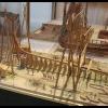
Part 40 – Aft Half Frames 1
As in the forward section, the aft half frames lie between the cant frames and the aftermost of the full square frames. They bolt to the vertical side of the deadwood and are square to the line of the keel. When installed they will be hard to distinguish from the full frames that rest on the keel. However when the horizontal bolts are installed the difference will be more obvious.
I installed the first of these following the method used on the forward frames. As shown in the first picture these, although separate, were fabricated as a single assembly held together with temporary cross-spalls. This assembly would then be slipped over the deadwood at the correct height. The breadth at the top is held by the spalls and alignment set using the center string line.
The next picture shows the erection method.
The sides are contained by the two clamped squares located at the line on the base drawing. The center of the spall is marked and aligned with the string. The height on both sides is set using the vertical caliper based on heights taken from the drawing. This worked well except that gluing and accurately clamping at the deadwood was a bit involved. I soon adopted the simpler method shown in the next picture.
In this method the two frame halves are installed separately. The ribbands at the planksheer were extended back into the cant frames. These ribbands are then used to set the height and breadth of the frames at the top, where they are pinned tightly through the ribband as was done for the full frames. This method roughly mimics actual shipyard practice.
This turned out to be a very much simpler method with equal accuracy. In the next picture a half frame has been lightly clamped at the bottom and the frame is held so the top of the aft top member is at the top of the ribband. The ribband has been marked with the joint line of the frame for fore and aft alignment. A pin hole is being drilled through in the picture.
Once pinned at the top it is an easy matter to rotate the frame to apply glue to the face, then position and clamp it in place by one of the methods shown above. This process is almost too simple. However, it does depend on an accurate ribband line.
To help assure this, a spreader was inserted and pinned at frame 33, about midway in the remaining open space. Sized from the pattern for 33, this helps maintain the correct curve of the ribband breadth. This spreader and two measured strips are shown in the next picture.
The strips are loose and were merely used to check the breadth at the last full frame and the last installed half frame.
The last picture shows the hull at present. The remaining gap in the framing should soon be filled.
Apart from the clutter of my workshop in the background, this picture gives an idea of the length of this hull – and of the L/B ratio. This is one long slim ship - roughly 240 feet long by about 43 feet broad – about 6/1. Naiad: 3.7/1.
Ed
-
garyshipwright got a reaction from Jeronimo in HMS Montague 1779 by garyshipwright - 74-gun Alfred-class
Hi everyone, I went and made a few items to go with the stove but after looking in on Remco stove and pot's, find his to be a lot cuter so going to have to do a little face lift on mine to make them just a tad cuter, if that's possible Beside got to thinking, whats a stove with out pot's and pan's. Remco see what you went and made me do. Gary
-
garyshipwright reacted to DORIS in ROYAL CAROLINE 1749 by Doris - 1:40 - CARD
Dear friends,
thank you very much for your compliments and kind words, I appreciate them a lot.
Today I took a video to show you the tutorial, how I make the belaying pins. All is handmade, cause I have not any special tools.
The pins are solid enough, even if they are made of two parts.
And what's new on RC.....
I have finished spiral staircase - it is made of paper and covered with foils to imitate wooden look.
Kind regards
Doris
-
garyshipwright reacted to Jeronimo in LE BONHOMME RICHARD by Jeronimo - FINISHED
Hi friends,
cannons for assembly on the Gun-Deck prepared.
Karl
T e i l 4 1
-
 garyshipwright got a reaction from 42rocker in Licorne 1755 by mtaylor - 3/16" scale - French Frigate - from Hahn plans - Version 2.0 - TERMINATED
Hi Mark.
Just to let you know sir, the French did have sister frames like Hahn did, only they were thicker sister frames. Your right they didn't have cant frames but one and this would have been all the way back at the stern, which I do believe was the fashion frame that connected the stern framing with the last square frame at the aft part of the ship. As far as the spacing have to agree with you, this also was different then what Hahn did and at the moment am unsure of what that is but will take a look in the Boudroit books and let you know. If you need any kind of information on the French ship sir, please let me know. I have quite a few of the Boudriot books and will be more then happy to pass along any info that you may need to help you. I have the L'Amarante of 1741, the La Renommee of 1744, the Salamandre of 1752 and the Boullongne of 1759 which should help you build her in her time frame. Look forward to your new build sir.
Gary
-
garyshipwright reacted to Dan Vadas in HMS Vulture 1776 by Dan Vadas - FINISHED - 1:48 scale - 16-gun Swan-class sloop from TFFM plans
Yeah John, I'm full of them (it??? ).
Here are a couple of pics of the Channels fitted to the Port side :
Sheer Rails
The Channels intersect the Sheer Rails, which is why the channels had to be fitted first :
An unusual way to hold the end of the sheer rail whilst the glue dried - clamps were ineffective in this situation, so I've temporarily glued a piece of scrap to the end of the channel :
Danny
-
 garyshipwright got a reaction from mtaylor in Licorne 1755 by mtaylor - 3/16" scale - French Frigate - from Hahn plans - Version 2.0 - TERMINATED
Hi Mark.
Just to let you know sir, the French did have sister frames like Hahn did, only they were thicker sister frames. Your right they didn't have cant frames but one and this would have been all the way back at the stern, which I do believe was the fashion frame that connected the stern framing with the last square frame at the aft part of the ship. As far as the spacing have to agree with you, this also was different then what Hahn did and at the moment am unsure of what that is but will take a look in the Boudroit books and let you know. If you need any kind of information on the French ship sir, please let me know. I have quite a few of the Boudriot books and will be more then happy to pass along any info that you may need to help you. I have the L'Amarante of 1741, the La Renommee of 1744, the Salamandre of 1752 and the Boullongne of 1759 which should help you build her in her time frame. Look forward to your new build sir.
Gary
-
garyshipwright reacted to Dan Vadas in HMS Vulture 1776 by Dan Vadas - FINISHED - 1:48 scale - 16-gun Swan-class sloop from TFFM plans
Thank you very much John, Colin, Doris and Popeye .
Fitting the Channels perfectly horizontally was accomplished by the use of a couple of specially made "jigs" that sit on the planksheers from one side to the other. Masking tape and clamps hold the jigs firmly in position. The leg glued to the underneath of the horizontal member was measured at the inboard edge and cut square.
Danny