drobinson02199
-
Posts
1,079 -
Joined
-
Last visited
Content Type
Profiles
Forums
Gallery
Events
Everything posted by drobinson02199
-
 Chris: Yes, the instructions are pretty clear about it. What they say is "paper glue" -- whatever that is. I was originally going to use diluted PVA, which is what I used for the decorations, but I thought about it and felt that PVA would make the paper too hard to remove, so I used spray adhesive which is like rubber cement, but easier to apply uniformly. On side one I only used one spray coat, and the paper slipped off as I cut it, so I initially reinforced it with undiluted PVA (which was a bear to get off), but then started using clips while cutting the strips where I could remove the paper. On side 2 I sprayed two coats (wet -- one right on top of the other), and that solved the slipping issues, but some of it was harder to remove. The steamer fixed that. What Amati doesn't specify is HOW you are supposed to remove the paper. So that's up to the modeler to figure out. It all gets painted, so the color marks that sanded paper leave on won't matter as long as it's smooth. I suppose that the alternative would be to laser cut all the strips, but then there would still be the challenge of getting the portholes drilled exactly, which is what the paper strips on the first 4 rows do. Regards, David
 -
Chris: I think I understand your question. For the strips not yet glued where I can remove the paper, I just slip a knife under it and slowly pry it up. The spray adhesive loosens and it peels up. The few remaining spots then sand off. For this second side, I found that this worked for most of the other strips glued to the hull as well, and then I had to go back to the steamer. I think spray adhesive works well for this. When I used PVA glue on side 1 to strengthen things, the paper was much harder to get off and I had to use the steamer all the way. Regards, David
-
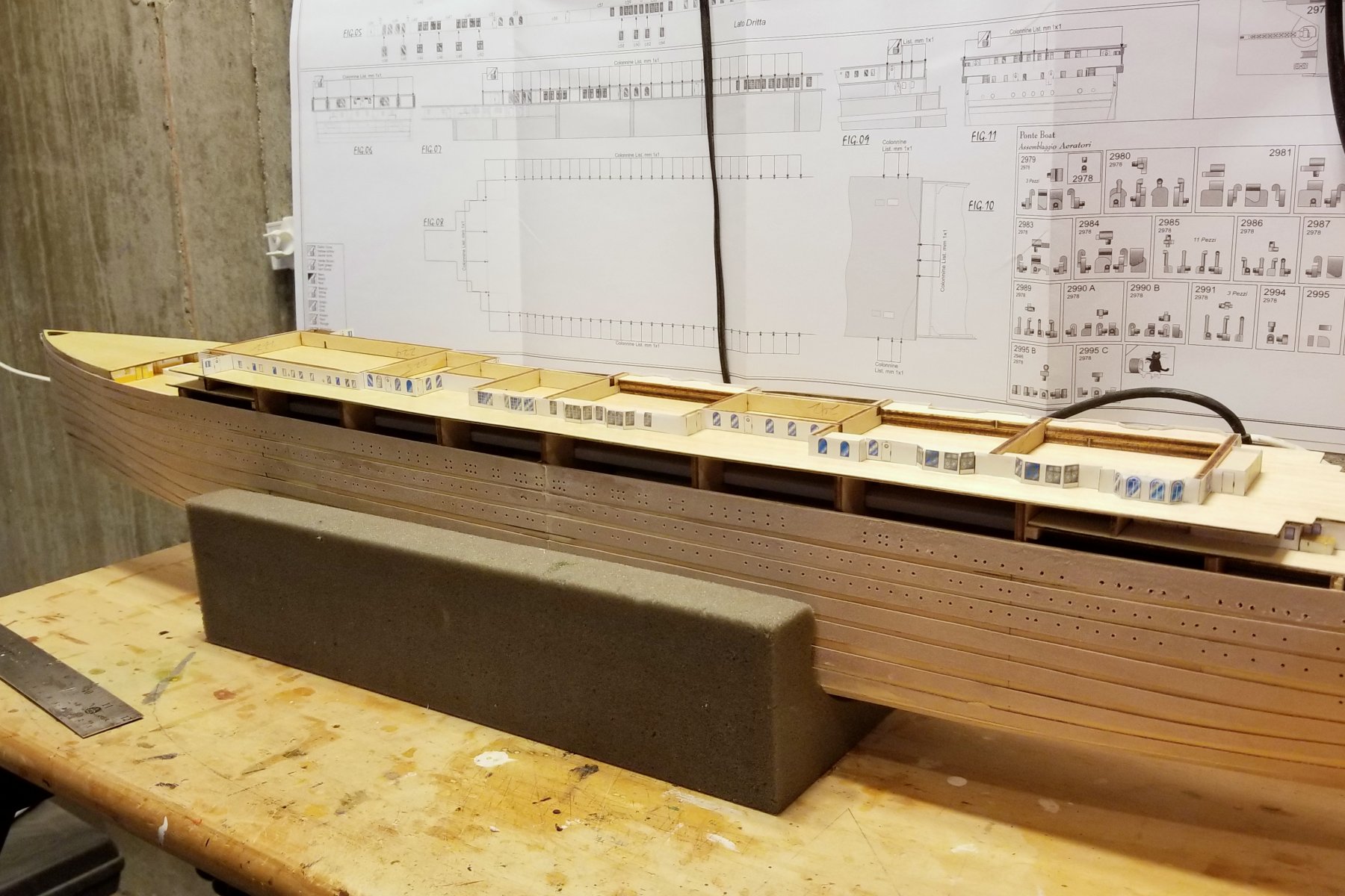
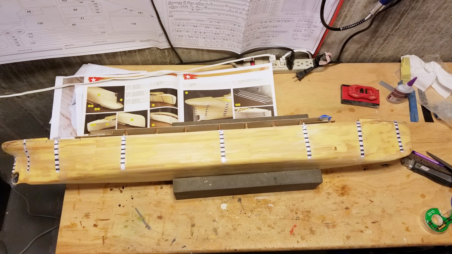
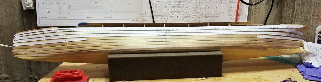
Second side strips now on. The approach of not cutting the paper strips precisely until they are glued onto the plywood worked much better. It's hard to keep a straight edge when cutting paper only, but when cutting the thin plywood it's very easy to get a straight edge. You can't see it in the picture, but this side looks much more even and finished than the other one. Fortunately, it's my planned "display side." Regards, David
-
Chris: On the starboard side, I used one layer of spray adhesive, and found that I had to hold the paper on with clips while cutting as any bending caused it to begin to loosen in spots. For the upper strips where the paper had to stay on for porthole drilling, I had to reinforce it with paper glue in order to cut it, and that in turn meant using my steamer and the back edge of my knife to peel it off. The lower strips came off easily before gluing as they were ready to. For this side (port), I have used a double layer of spray adhesive. I have cut out one strip already, and it held much better -- so I'll now see later how easy it is to get off. I did notice that this approach of leaving wide borders is much better and leads to much cleaner and straighter edges on the strips. Regards, David
-
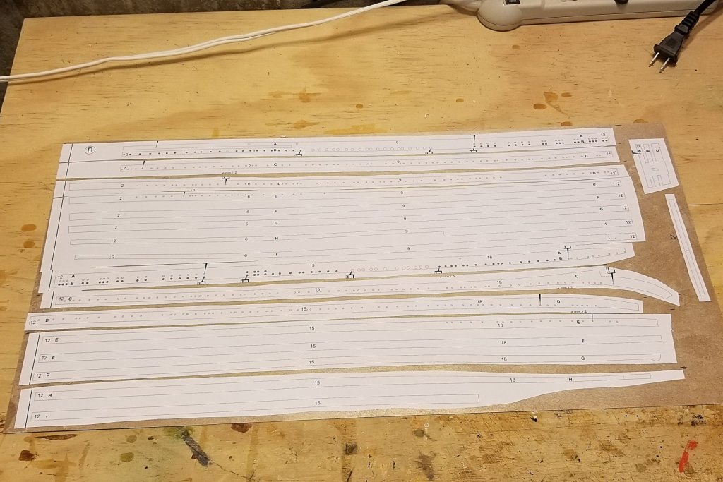
I was able to cut another step from side 2 strips. The instructions have you carefully cutting the strips, then pasting them onto the thin ply, then carefully cutting them out again on those outlines. I realized that I only have to be careful the second time, so I did a rough cut of the strips (so they would all fit onto the plywood sheet), and then pasted them on as shown. Was able to paste some sets of 3-5 strips intact. Took about 15 minutes all in, vs. maybe 90 minutes the other way. Now I'll cut carefully. Regards, David
-
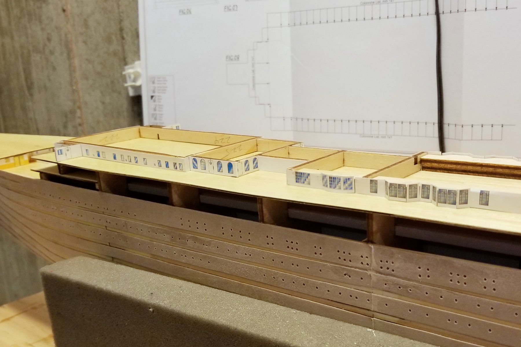
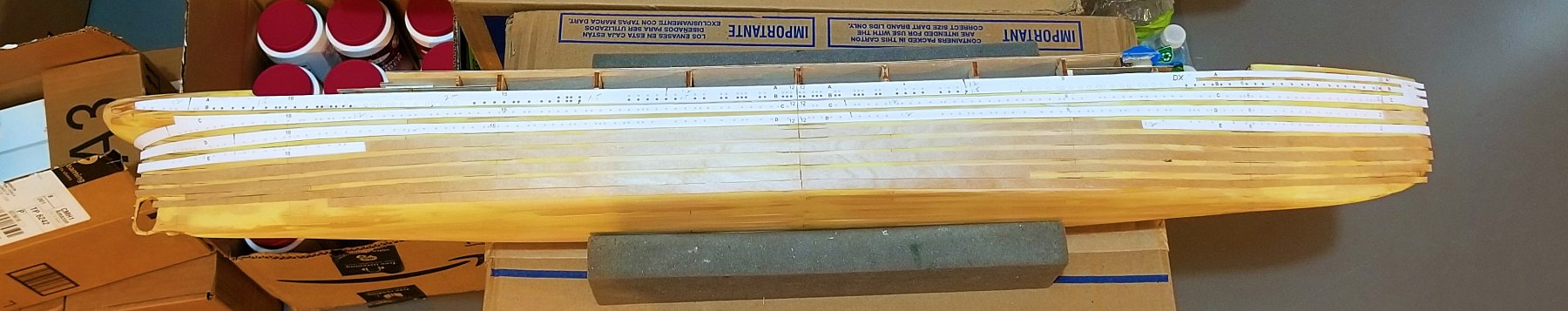
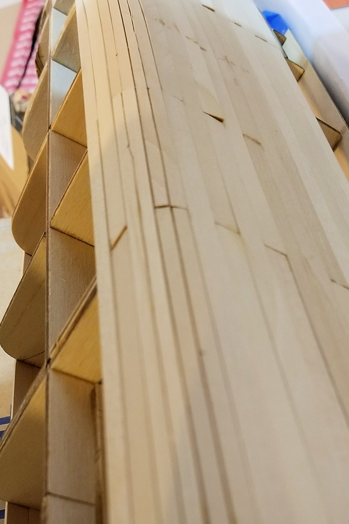
Finished the strip mounting on one side. It's tough to keep the lines straight when you cut out the strips, even using scissors. The other issue is that as you cut the long strips, they curl up to clear your hand and the paper tends to separate. I dealt with this by using small clips on the paper as I cut, but in some cases I had to re-glue them down using PVA. The first picture shows all of the strips mounted. My modified alignment process worked really well, and having done it this way I am really glad I avoided the two step process with pencil outlining as specified in the instructions. That would have been really messy. Where there were no portholes to be drilled, I was able to remove the paper before mounting, which was fairly easy. The instructions save porthole drilling for later (until both sides done), but I was concerned that when I flip this over in my foam cradle the friction as I work on the other side would pull off some of the paper (which marks the porthole and hawse hole locations), so I went ahead and drilled the portholes and filed the hawse and scuppers, and then removed the paper. After some trial and error, I found that the best way to remove the paper is like wallpaper removal, using my steamer continuously along the strip while running the back side of my knife (like a smooth chisel) along the strip. Second pic shows the strips with portholes drilled & paper off. There is some more finish sanding to be done on these, but I want to be careful, as the strips are very thin. Regards, David
- 168 replies
-
- 10
-

-
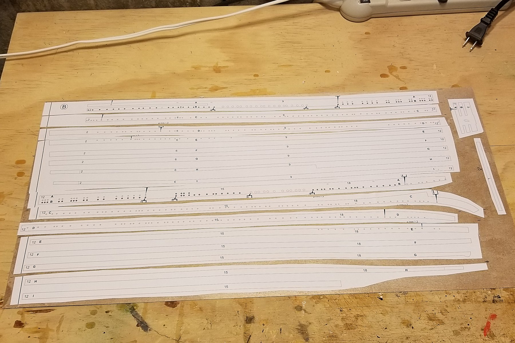
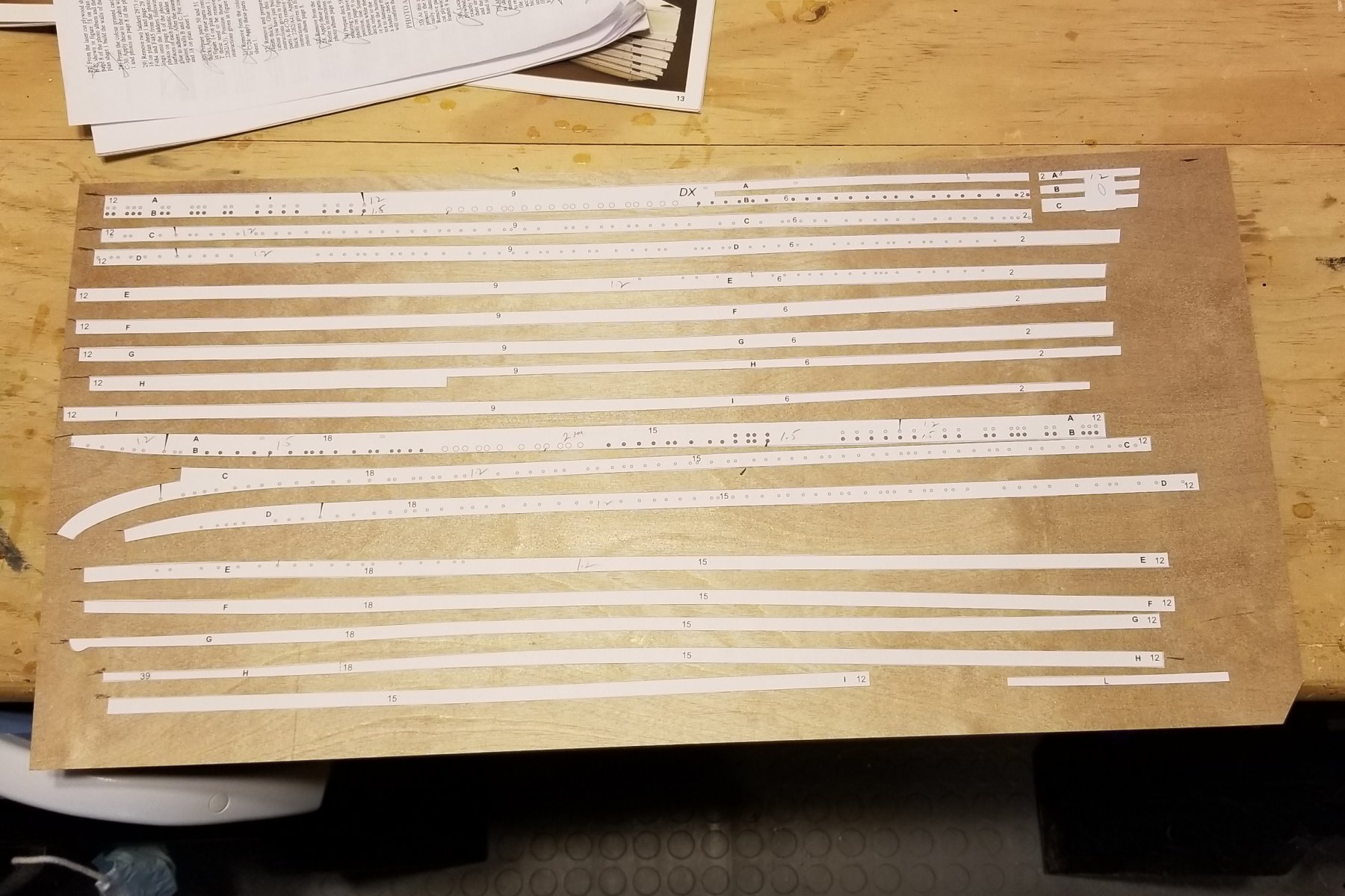
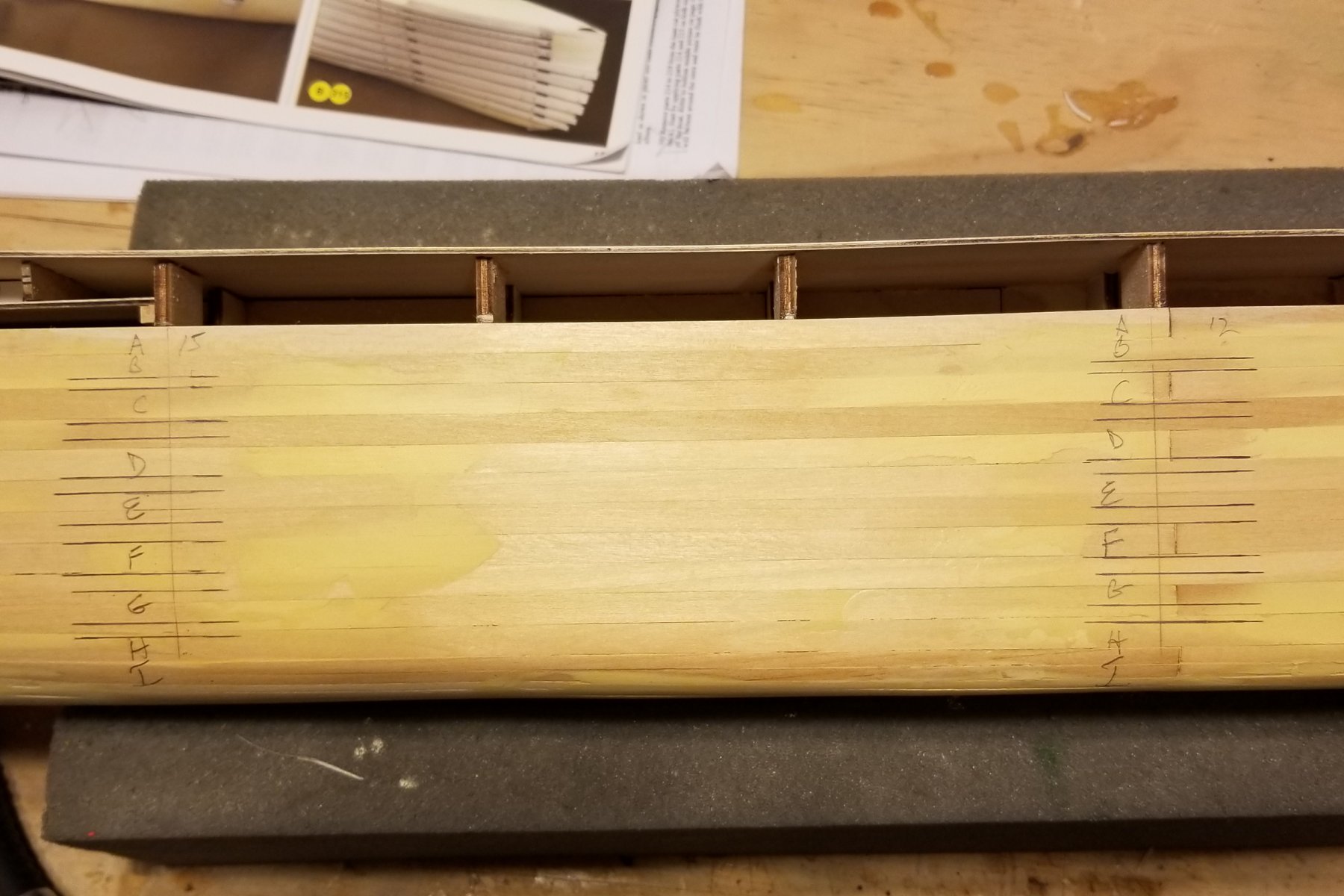
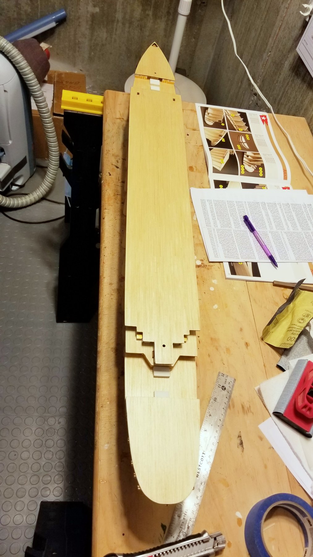
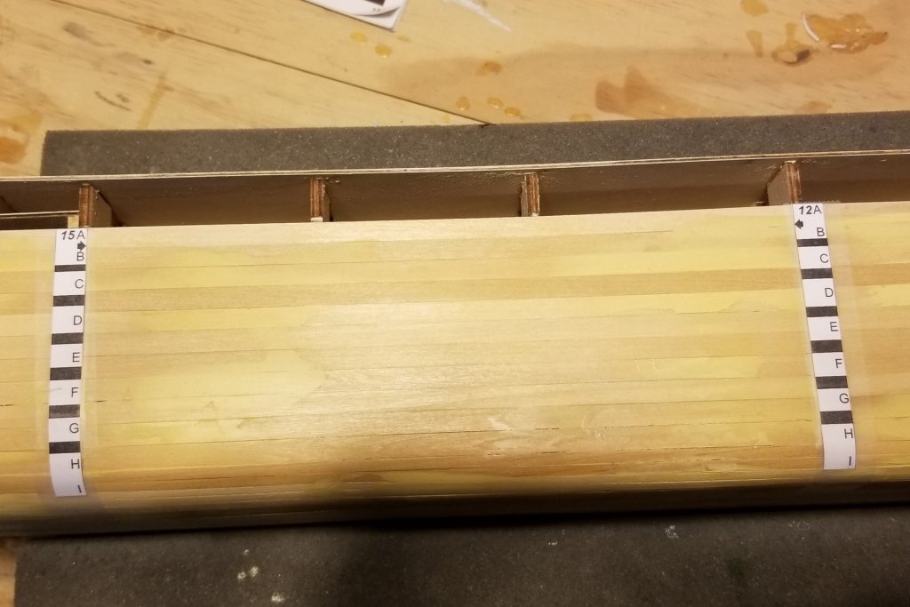
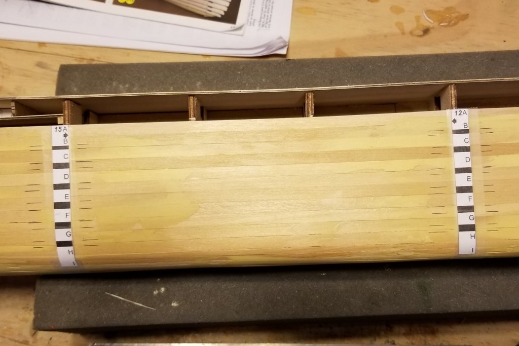
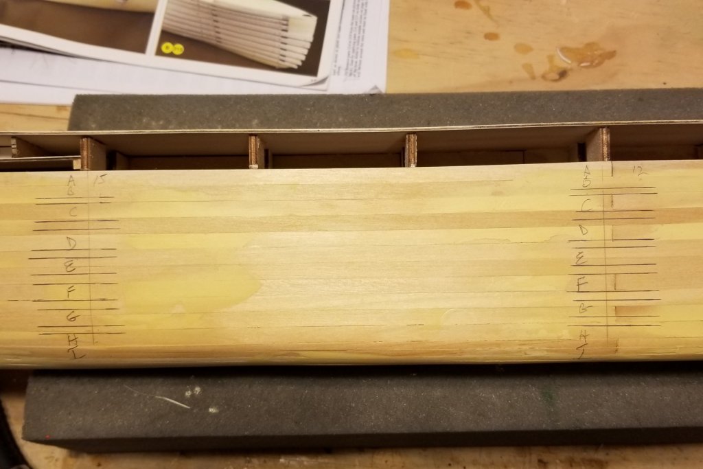
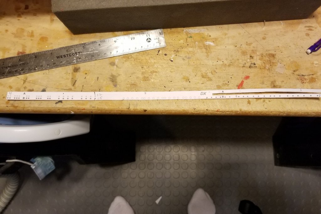
Pic 1 shows the horizontal paper strips mounted on the thin plywood. I used spray adhesive. They are then cut out for mounting on the hull according to the guides pictured in my previous post. The instructions call for mounting the strips with pins only (there are about 18 on each side), then outlining them in pencil, then removing them to remove the vertical guides, then gluing them on again. I realized that the only reason for that two-step process is to get the vertical guides off the hull, and it occurred to me that I could just pencil mark their position, then remove them, and then mount the horizontal strips with glue in one step. Pics 2-4 show the marking process, and it should save me a bunch of time. I also hate pinning things as the pins come loose, or put holes in the wood that have to be filled, so this avoids that. Pic 5 is the first strip I've cut out. Strong sharp scissors work fine. I'll post again when I have some strips glued on. Regards, David

- 168 replies
-
- 10
-
-
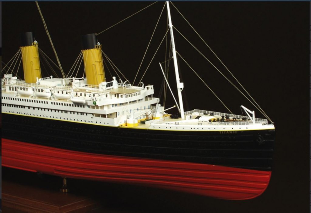
Ben: It's not a true second planking. It's horizontal hull-length strips of wood, with spaces in between. You can see the effect in the attached Amati picture. The pattern you see on the red colored hull runs all the way up to the top of the hull on the black part too. All of the pictures of the real Titanic are B&W, and the pattern isn't visible on the black hull (red is below the waterline). The strips have to be cut from a sheet of ply using paper patterns, which should be a real trip. Regards, David
-
Addendum: the other thing that happened is that I hit the end of the stern opening you can see and the rear half of the arc broke off. So I glued on a short piece of planking and then shaped it with my rotary tool sander, and it came out looking pretty good. All of which is to say that this step was full of pitfalls. Regards, David
-
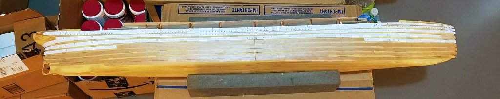
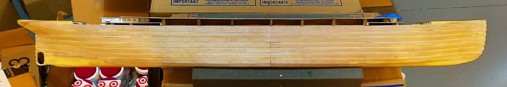
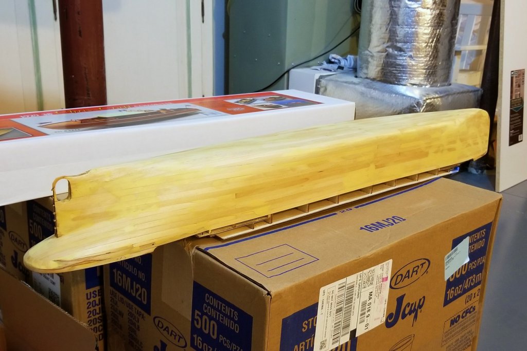
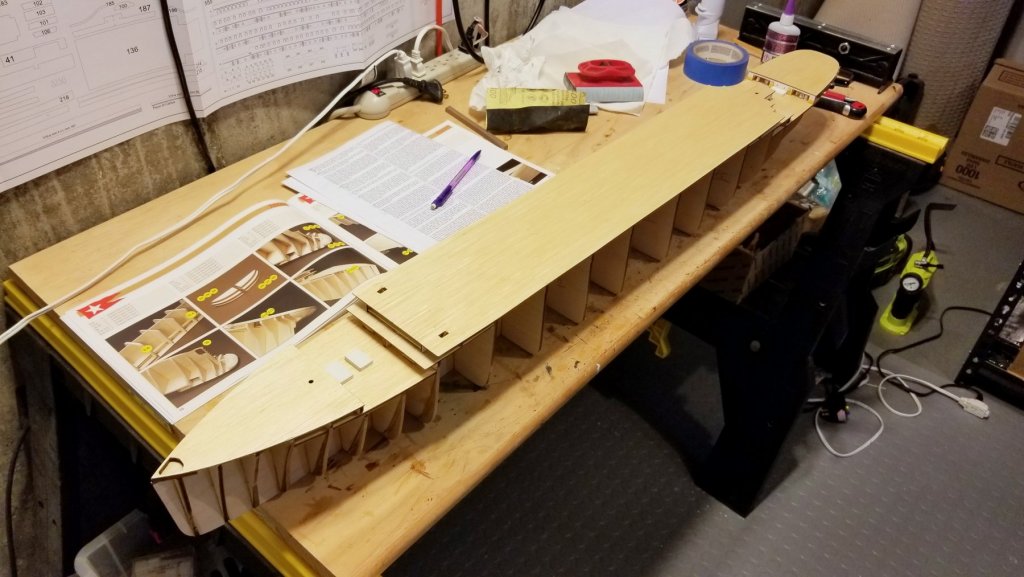
First hull planking completed -- see picture. This was an interesting process with some "learning points" for me. I decided to buy a sheet sander -- and it really worked well getting the hull planks smooth. The problem was that it worked TOO well and some of the planks are now very thin. I think my mistake was using the same grit (120) for the electric sander that I had started to use with my sanding block. The electric sander is so efficient that a higher grit would have been better for the first sanding -- probably 180. Nevertheless, it came out pretty well overall, and with some help from wood filler and a coat of varnish, it's done. Now on to second planking. I'm going to have to be careful when I use pins to align the second planking to make sure I'm going into thick enough planks. Regards, David
-
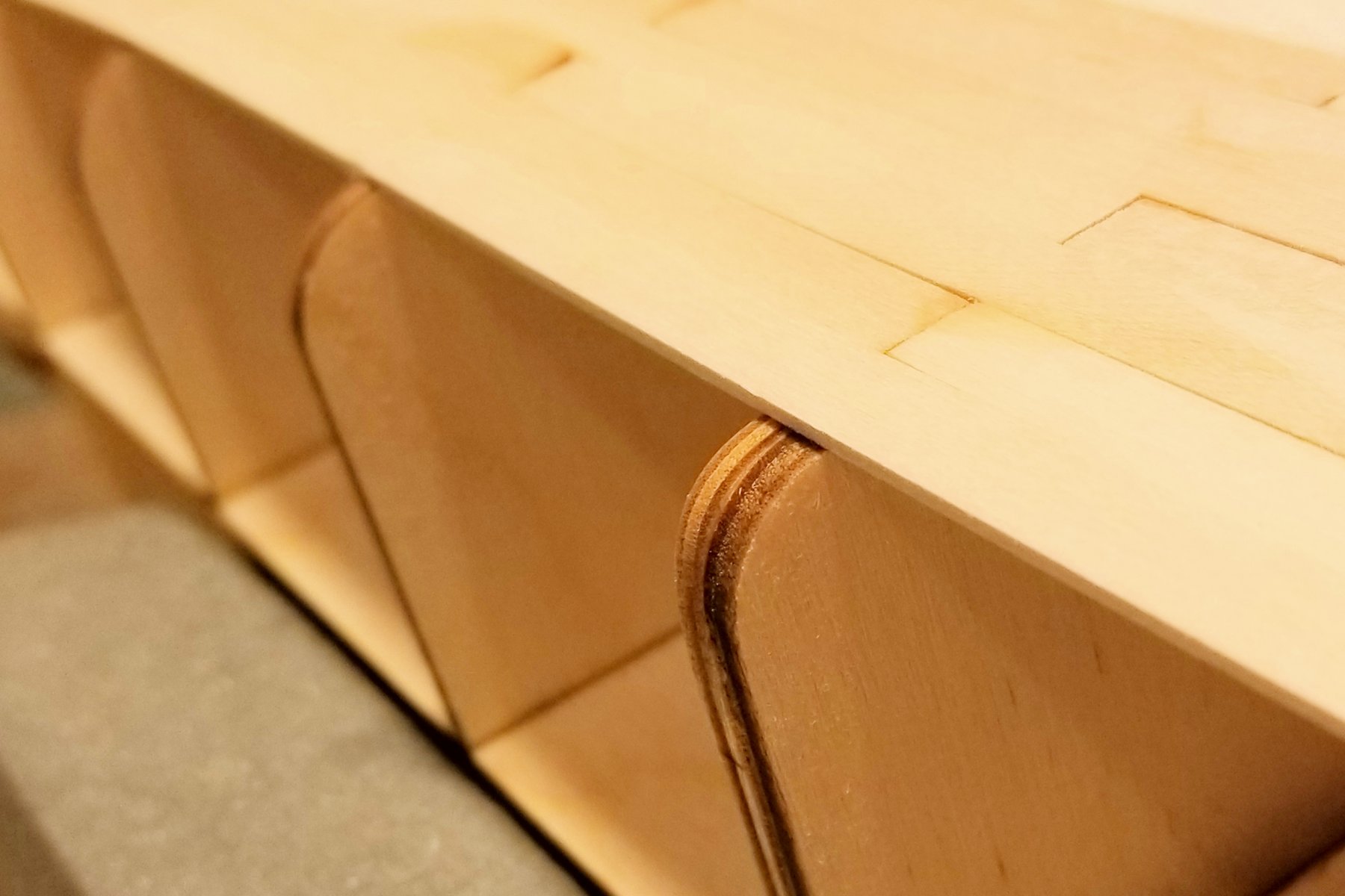
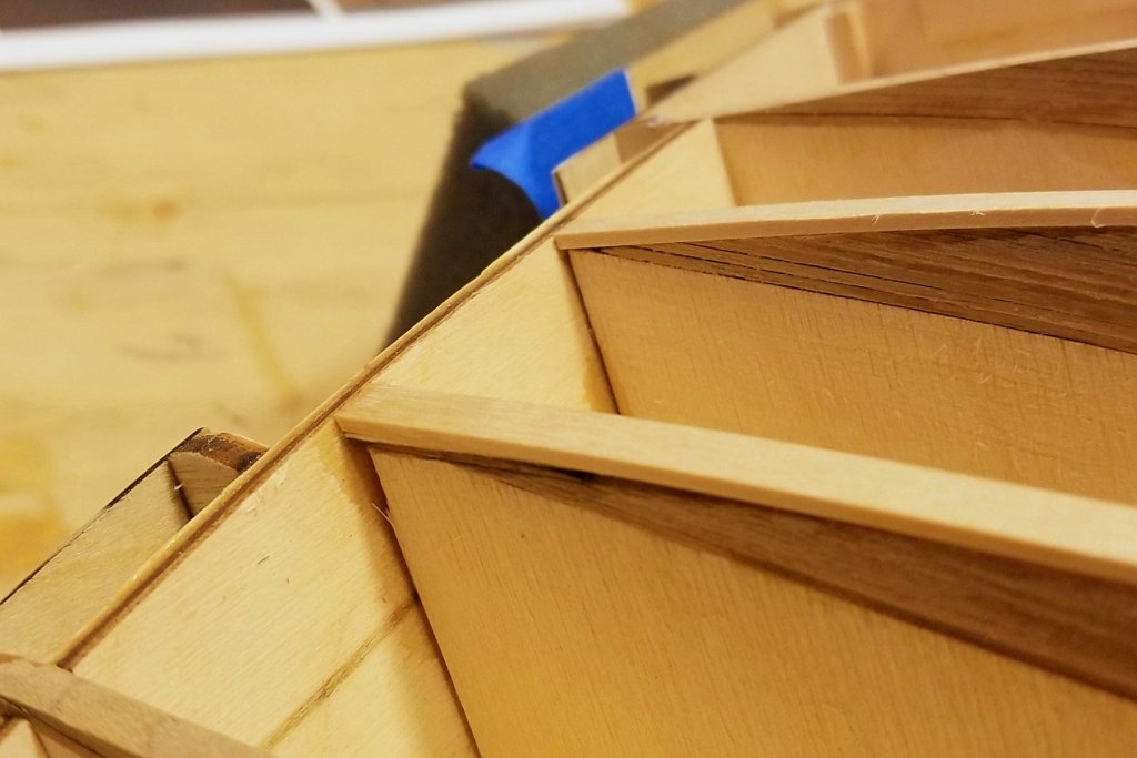
The center of the Titanic's hull is tub-shaped, so the center frames make a sharp turn from the side to the bottom (Pic 1). The planks at 7mm wide would make bad wraparound on those frames (Pic 2). The obvious answer was to cut the planks lengthwise, but I was concerned that those cuts wouldn't be even (too long for my planking vise) and therefore wouldn't butt well. The solution was to split them partway with my knife (Pic 3) -- since only a part of one plank goes over the center frames, I could keep the rest unsplit. That meant that I could mount them with the split edges mated and get a good curve, as shown in Pic 4. Regards, David
-
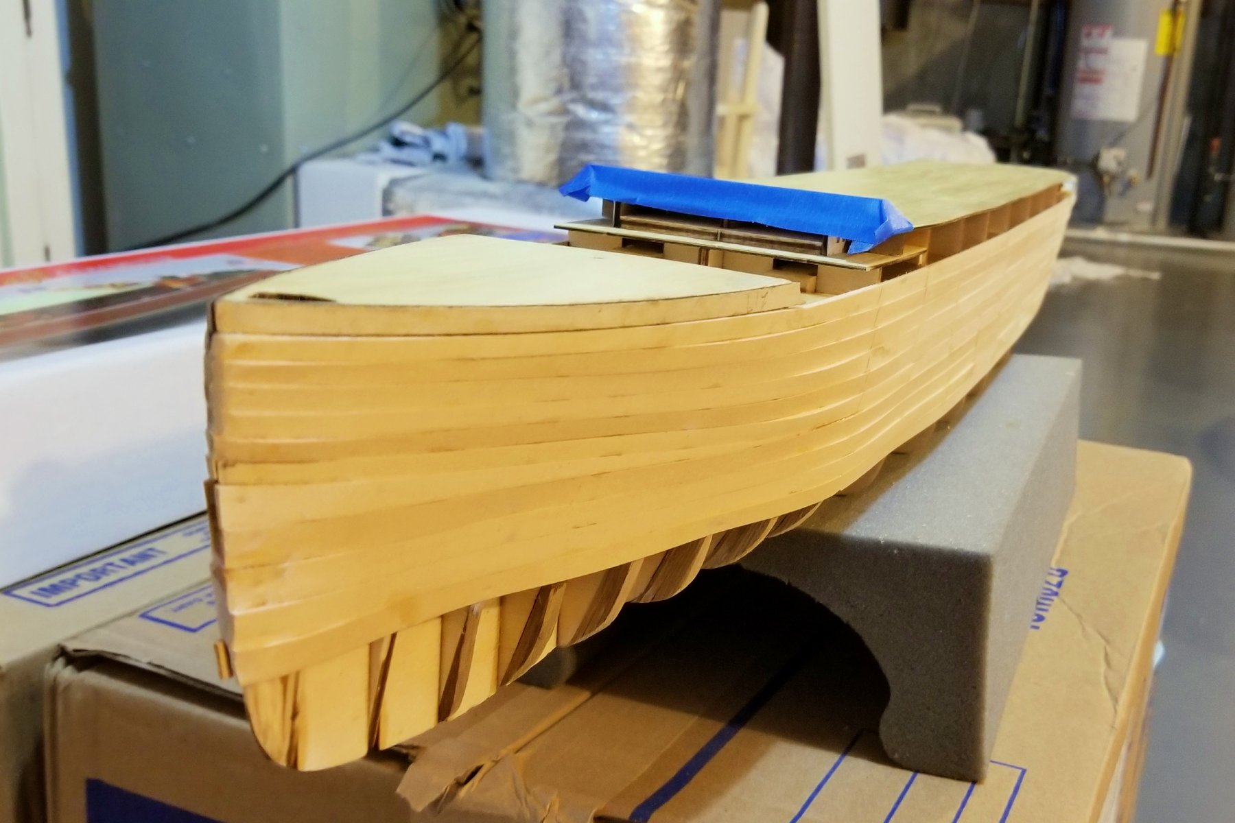
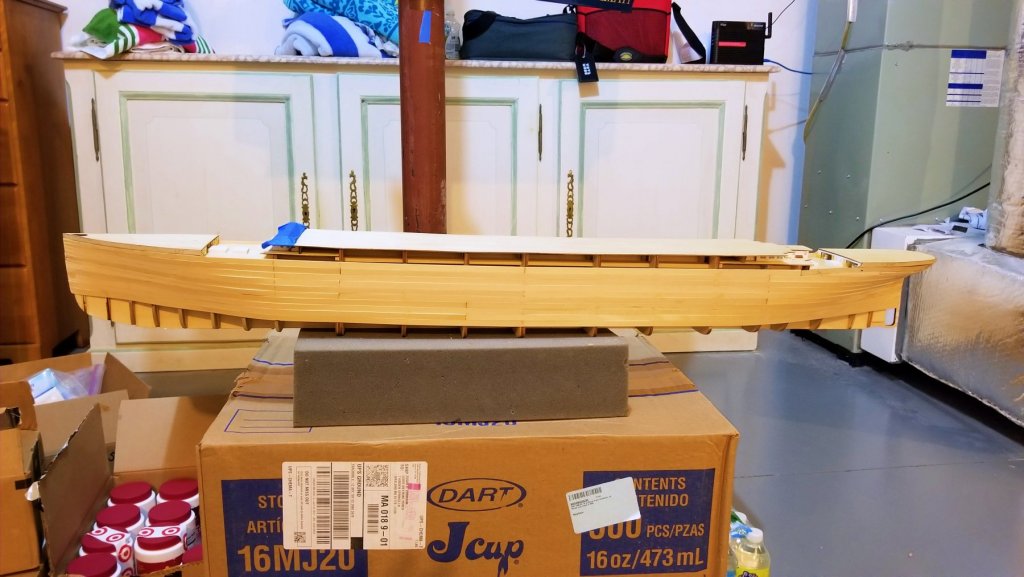
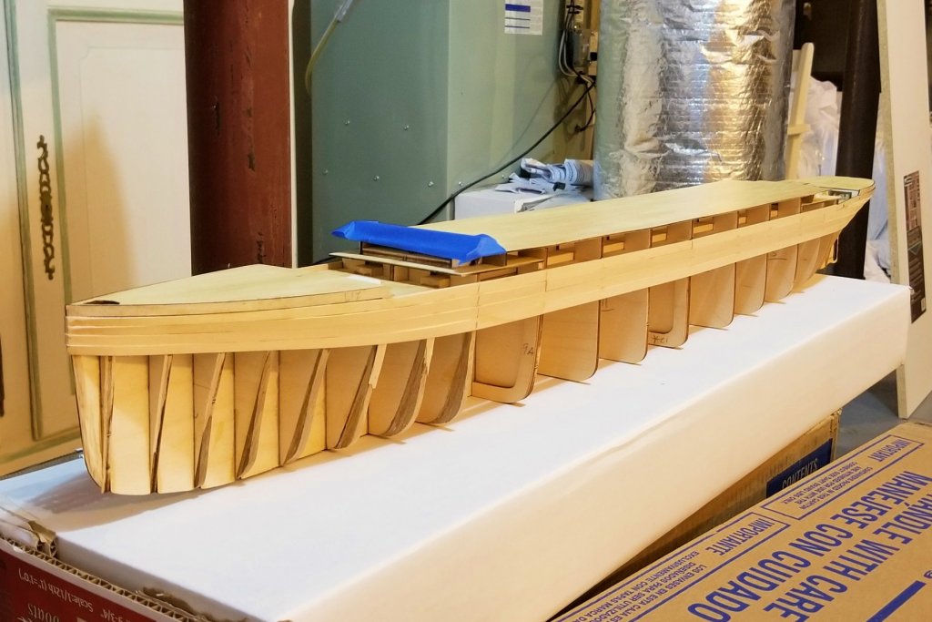
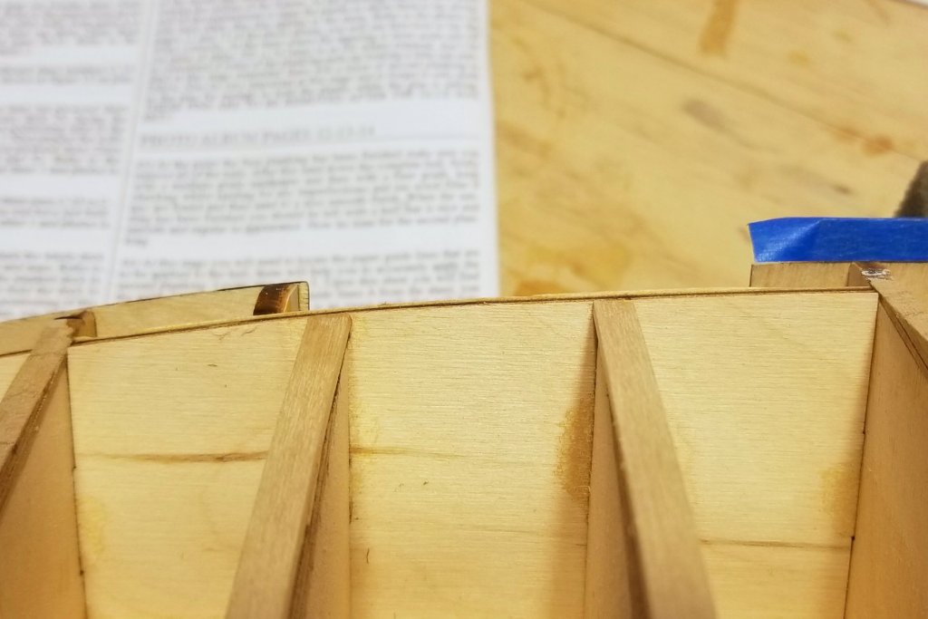
Progress on first layer planking. For those of you who read the earlier posts on adjusting the shape of the bow frames: in the second pic, you will see how the shape of the bow is coming out. On the Amati pics of the model, the bow narrows sharply just where you see the blue tape on mine. As you can see, mine with the adjusted frames begins narrowing a bit further forward, and the narrowing slope is more even. Regards, David

- 168 replies
-
- 10
-
-
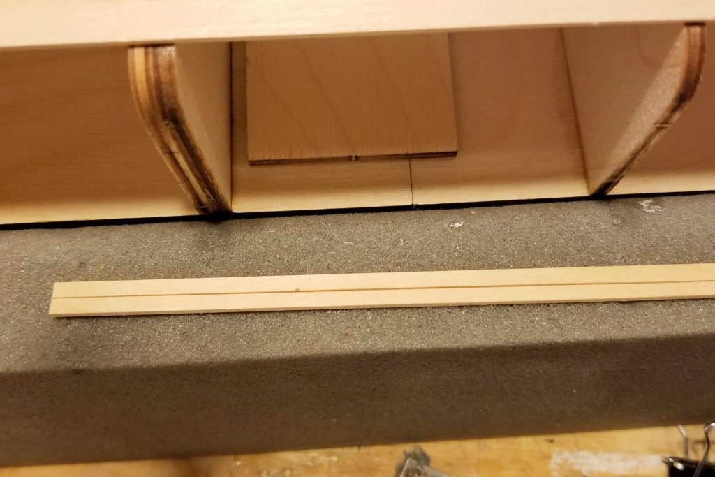
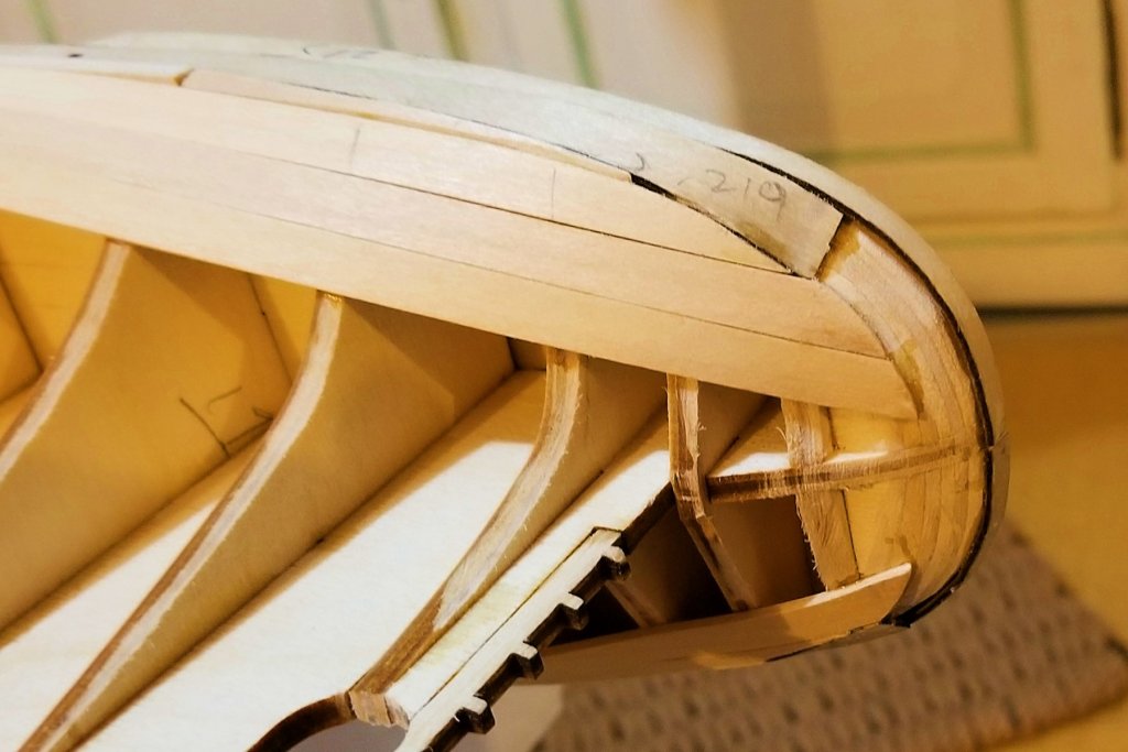
Popeye: It does get a filler, later on. It consists of trapezoidal wedges of planking fitted into the semi-circle. I've been taking care to shape the ends to create a smooth circle so I won't need too much wood filler once the wedges are in. Regards, David
-
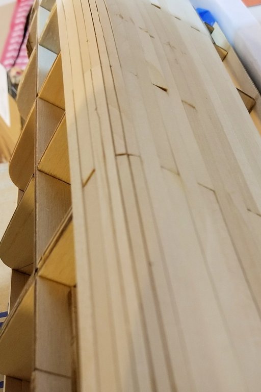
First layer hull planking started. So far this has gone pretty smoothly. At the stern, the planks need to be twisted with the steamer, but no side bending needed so far. I also had to put some stealers in at the stern just below the initial plank to align things between the laser cut sides and the initial plank, but they will sand/fill out. Regards, David
-
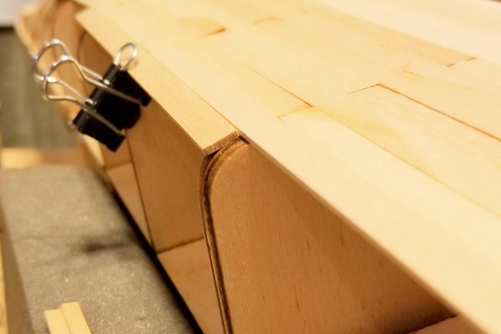
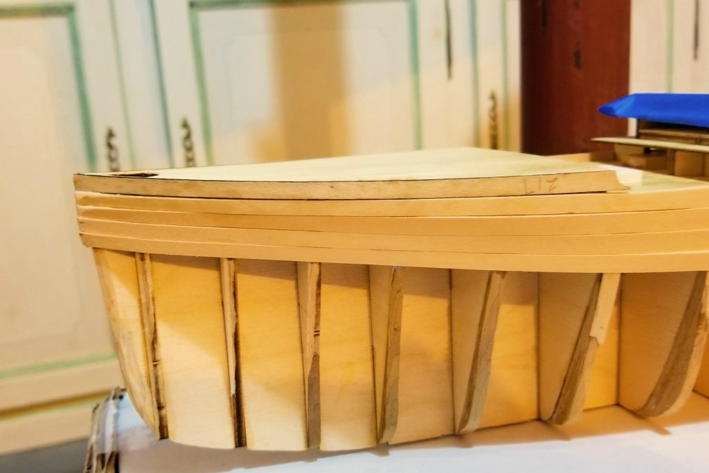
Initial bow and stern strips, and initial planking strip, in place. See pic below. I am posting this because I caught something at the last minute that the instructions aren't clear on, and that would have given me real problems later. The way the instructions read, you mount two stern laser cut strips first, and then butt the long planking strip up against the end of the second one. There are no instructions for alignment of the end of the second stern strip, so I just eyeballed the second one to look level with the horizontal hull structure. After I had glued almost all of the long strip, I began to worry about alignment with the deck above, so looked forward in the instructions, and sure enough, the distance is critical (16mm exactly from top of strip to bottom of deck), in order to fit a photo-etched piece in. What actually governs that distance is a set of very small notches in the frames, but they are easy to miss and I did. So I pulled up the long strip (fortunately the glue hadn't completely cured), and repositioned it exactly 16mm below, using the notches I could find after the rip-up, and a ruler for the rest. The way it should be done is to use a planking strip, dry-fitted under the notches, as the master guide, and align the stern strip end with that, and then finish out to the bow. I'll do that on the second side. There is no mention of the notches in the instructions, but they are obviously critical, so that's a big miss in the instructions. Regards, David
-
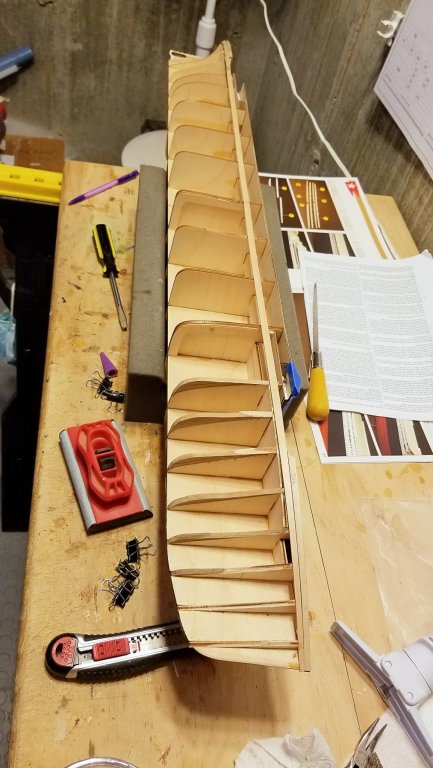
Getting ready for hull planking. In looking at how the frames align with the decks, I noticed that frames 6 & 7 fall short. If you look at the first pic, you'll see that the original frame is short -- not flush -- even after the laminated wood I added to bring the frames out. So I added some additional wood strip to bring these flush, which is what is required by the planking scheme. See pics. Regards, David
-
Chris: They are very narrow. As to length -- well, I have to confess that I didn't used fixed length planks on this one. I just ran the planking at full length, cut, ran the leftover the other way, butted in a new full length plank, and so forth. Simple reason -- a huge amount of this deck will end up being covered over. I'll likely slow down and do fixed length alternating planks on the upper decks. Regards, David
-
Another deck planked, mounted and varnished. Now the model turns over and a few structural pieces go on, and then the first layer of hull planking. Regards, David

-
Yes, the height to the top of the masts is 290mm. It's 215mm to the top of the stacks. Regards, David
-
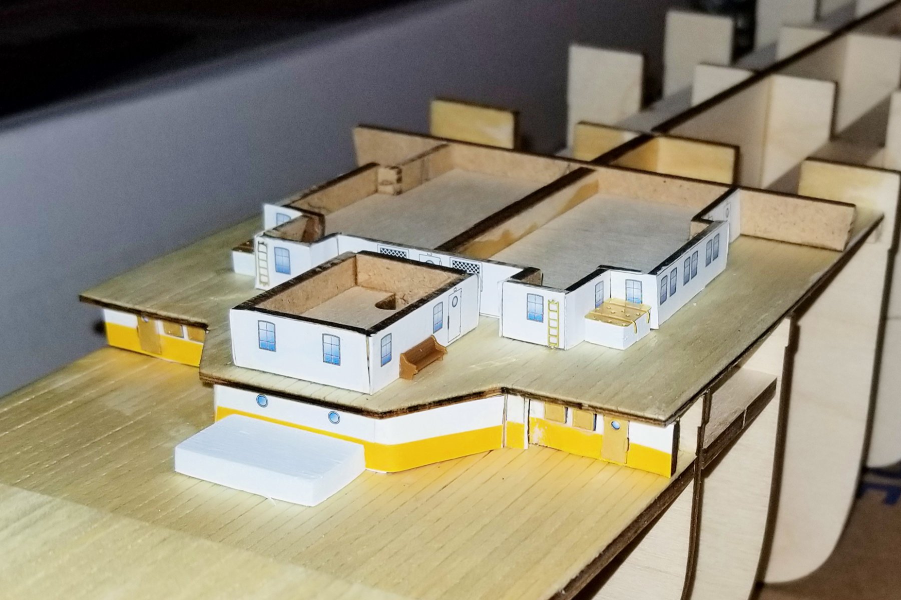
I took another look at the plans and instructions, and after the step-by-step instructions finish with the first photo book (pp 1-31), they start to reference the plan sheets, and when they do, all of the fittings and deck structures come into play, including the PE doors and windows. So there may be a bit more organization: you have to reference the plan sheets to build the cabin structures and apply the printed decoration, but then reference them again for the fittings later on. It looks like leaving them to "later on" may work. Regards, David
-
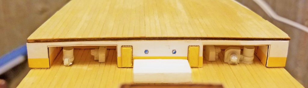
Mr. Pucko: My first book has 32 pages (back cover of parts pictures is page 32). The second book has 8 pages of photos, including front and back cover, but the important ones are the inside 6, which are all views of deck fittings installed. If you can't find yours, I'd be happy to send you some hi res pics of my pages, since there aren't that many. Let me know. By the way, when I went to assemble the parts under the poop deck, I was going crazy trying to find cast metal ventilator housings, until I finally saw that the fan housing is made of wood (while the other parts are metal). Easy to miss if your eye is looking for metal. Regards, David
-
Here's a shout out to Mr. Pucko for his comment about getting PE parts and other detail onto the ship as I go. He's right -- the instructions don't mention it, and so I looked hard at the plan sheets, and saw that the parts are indicated there. What's deceptive is that the very good picture book doesn't show these things installed as the build progresses. It isn't until you get to the second book, which shows all the deck fittings at once, that they show up in the pics. And as Mr. Pucko suggests, at that point the installation would be much more difficult because of access restrictions. So here are two samples of what I went back and picked up. And now I'll study the plan charts carefully as I build, and look for details. Regards, David