drobinson02199
-
Posts
1,079 -
Joined
-
Last visited
Content Type
Profiles
Forums
Gallery
Events
Everything posted by drobinson02199
-
 Zappto -- Two layers, sort of. A base layer, followed by narrowly spaced strips. Regards, David
 -
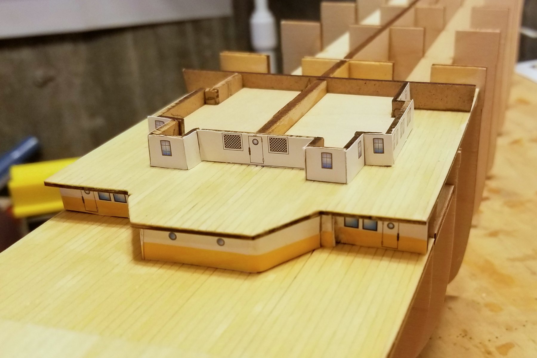
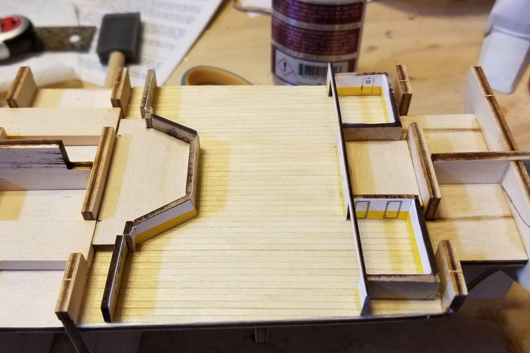
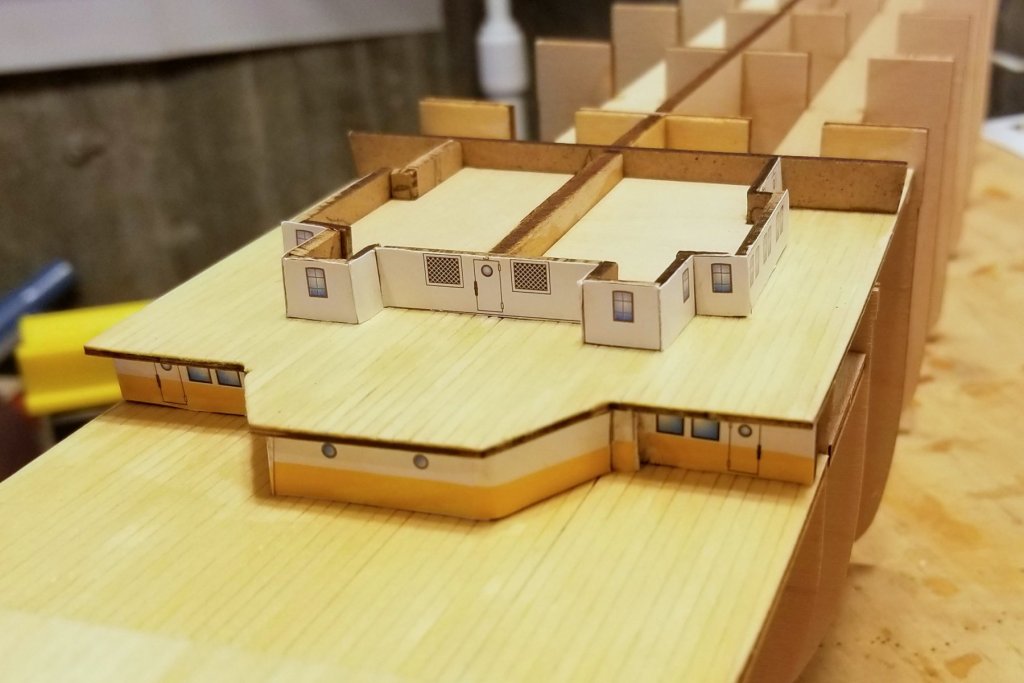
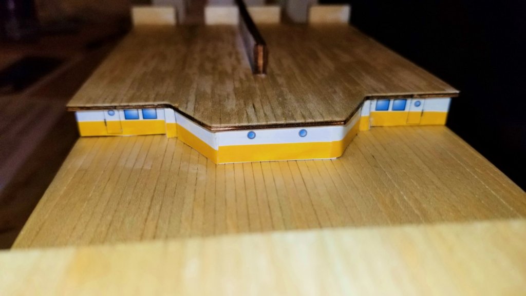
Another cabin structure built and decorated. I did this one differently. The manual says to build the structure, then cut out the pieces, and then glue them on. That leads to mis-fitted decoration pieces. So I used the cabin wall sections as templates to cut out the decoration pieces with a knife, then mounted the decorations to the loose wall pieces, and THEN built the walls. In the pic below you can still see imperfections, but to the naked eye it looks better than the one below it. Just takes a lot more forward planning. Regards, David
-
More progress with one more cabin wall done and all of the previously planked decks mounted. To address Chris's question: what you see is paper decoration glued onto the walls. Pic 4 shows it up close and you can see the imperfections at that distance. Pic 5 shows it at a more normal viewing distance. I would have preferred one continuous strip to mount so that there would be no seams between the pieces, which (at least for me) were unavoidable -- particularly on some very small pieces. But once the deck is mounted over the cabin walls, it looks fine (at a normal distance as I said). Re the decks: I'm clear coating them, which is the way they have it in the manual. Regards, David


-
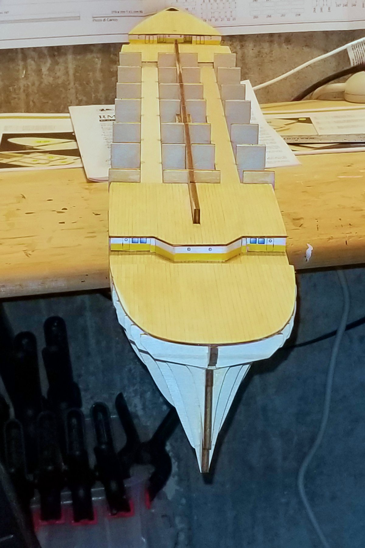
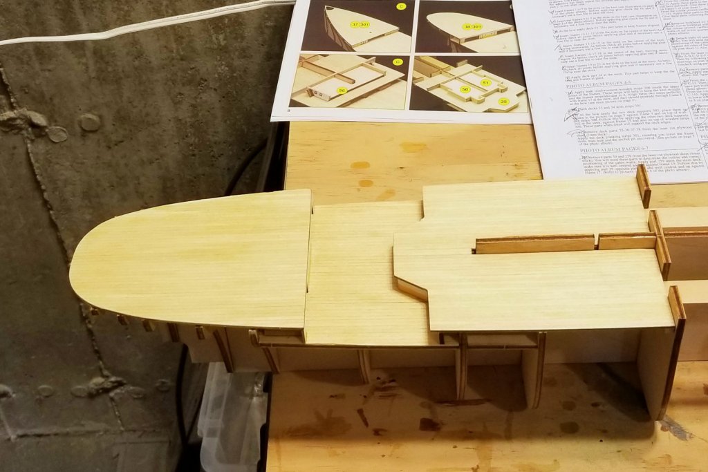
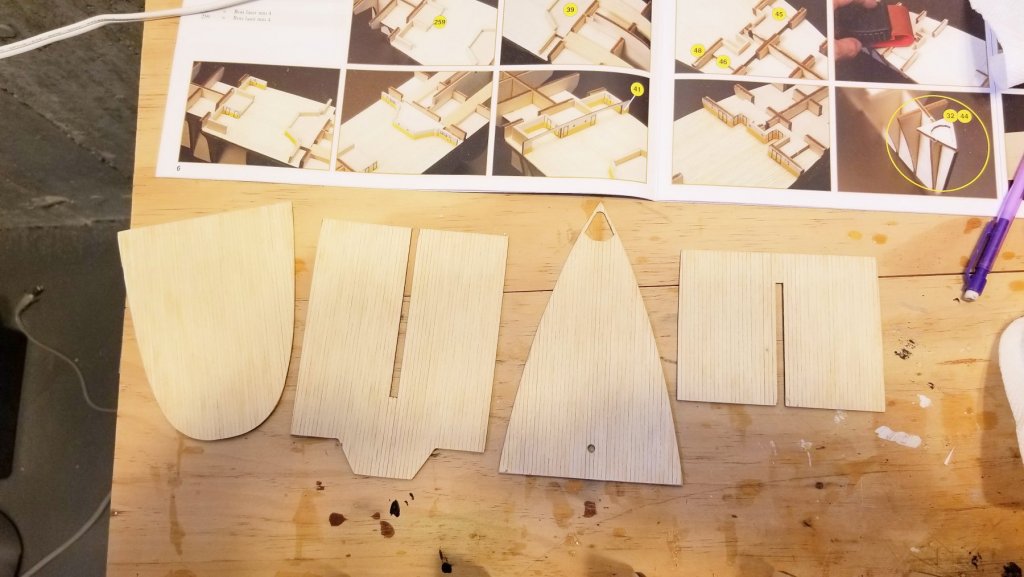
First two decks planked and installed, and cabin structures built on the stern deck. Other decks also planked, awaiting installation. Regards, David


- 168 replies
-
- 12
-

-
lgfrench -- I'll do it. I have always wondered why we don't see them posting in our model pages on this site, given how much feedback they could get. I wonder if they even follow their model builds. Regards, David
-
Chris -- If you look above in this thread, you'll see a post by lgfrench (who originally sent me the links on this) saying that he contacted Ages of Sail this past summer on this, and they contacted Amati and got nowhere. Ages of Sail is Amati's official distributor in the US. I don't think I've built a kit yet that didn't have some issue in the wood or the instructions. My HMS Fly had a serious lack of wood in some areas, which I was able to fix with my spare wood pile. On the other hand, the Revenge, a newer Amati kit, had tons more wood than was needed in all categories. I should admit that I'm paranoid about running out, so I really conserve wood as I go. Thanks, David
-
Chris -- She looks really terrific. How long is she? Regards, David
-
Dave: It is large, but I've seen some large ship models (like the Mantua Le Superbe and others) that are as large. I do have a large shelf, or I may mount it over the TV in my office. It comes with the smaller number of boats. Regards, David
-
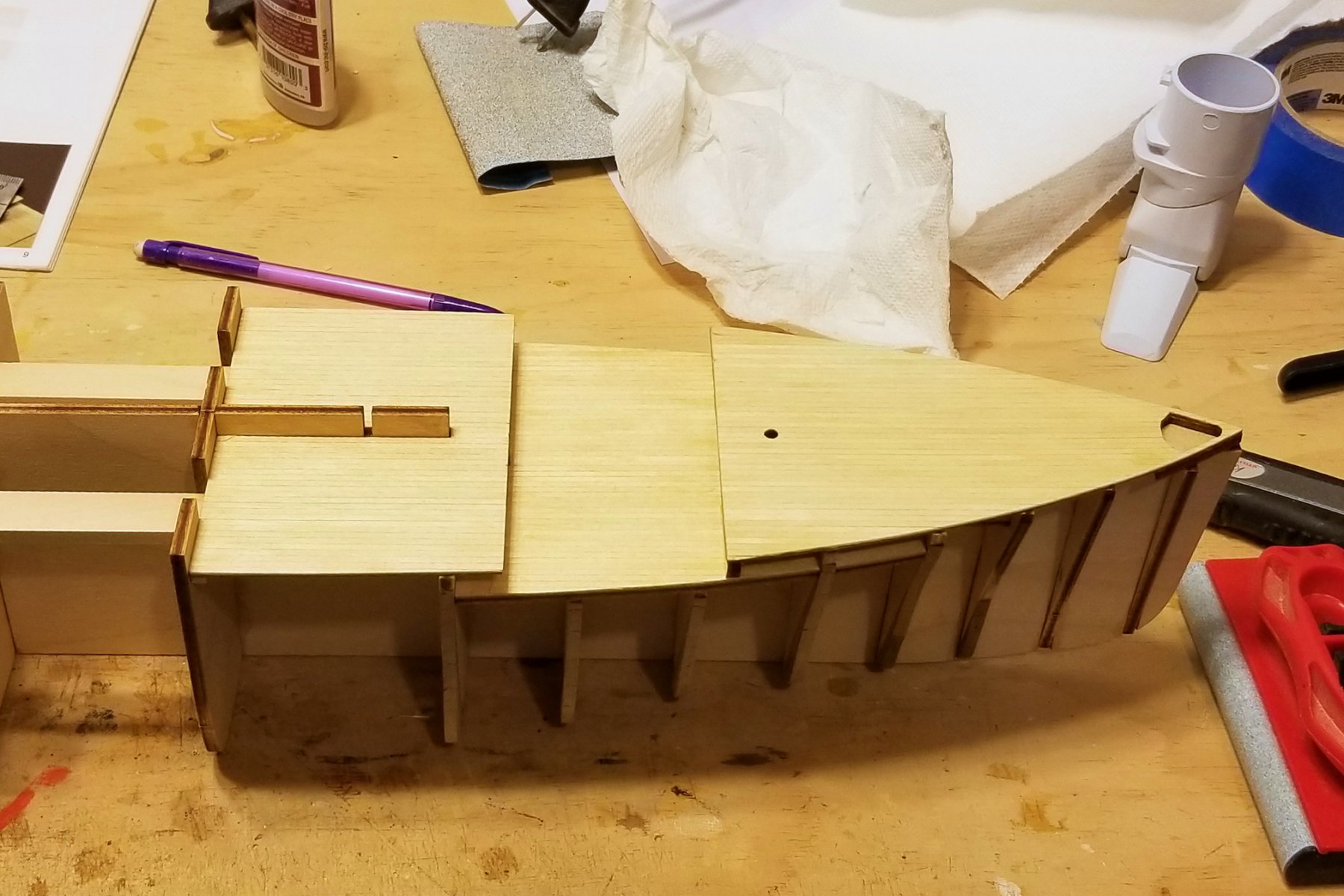
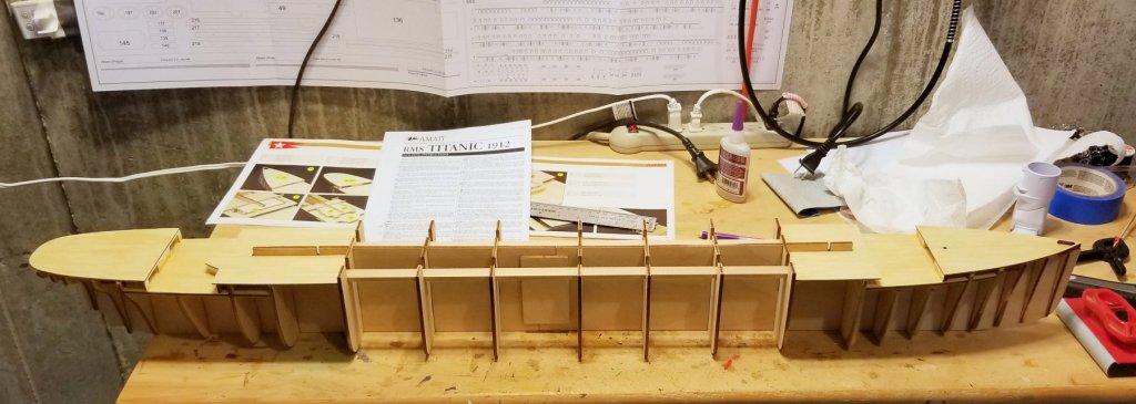
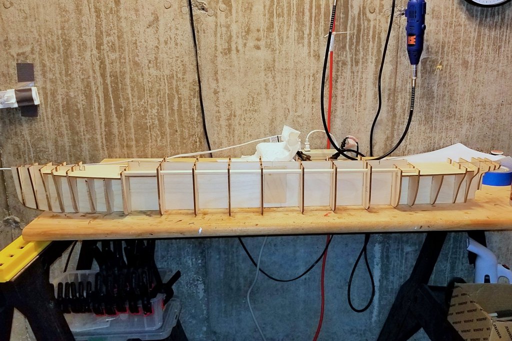
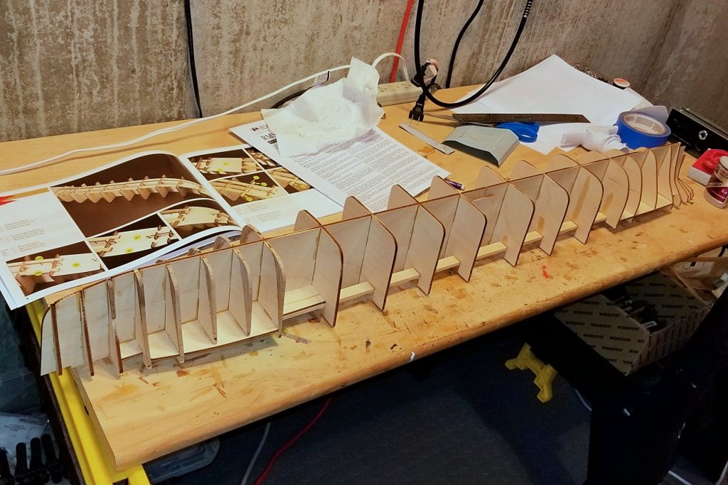
The basic hull framework is done, and it goes very smoothly. The laser cuts on the plywood are really well done and everything fit together without sanding or forcing. It's 42 1/4 inches long. The first two pics show the overall frame structure. The third one is the best of my attempts to show the adjusted bow bulkheads along with the line of the overall ship. When I sight down the hull, I think frame 5 has a bulge that's too far out -- and that may be because of the issue of printing/sizing the templates -- but it will be easy to adjust when I fair the frames for planking. The darker laminate makes it easier to compare the original line of the bow with the new line, and I like the new line much better. Regards, David
-
Yes, and since the new bulkhead templates were developed by the Titanic Research and Modeling Association, I felt they were credible and went with them. For a kit this significant, it would not be too hard for Amati to produce a laser cut of the new bulkheads (only 6) and ship it out to their main distributors (like Ages of Sail) as a free mod to the kit. I would have struggled with this if lgfrench had not taken the time to lead me to the mod. Regards, David
-
Great point, Chris, and thanks to Mr. Pucko for the follow-up. I guess I'll find out. Building this kit will be an adventure, and let's just hope I don't hit an iceberg! 😵 Regards, David
-
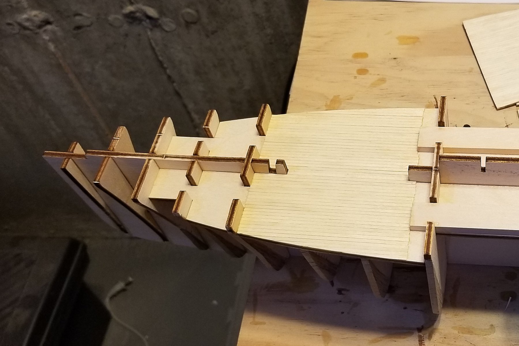
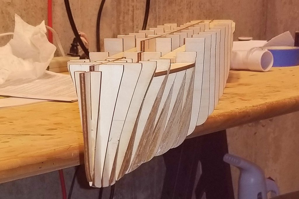
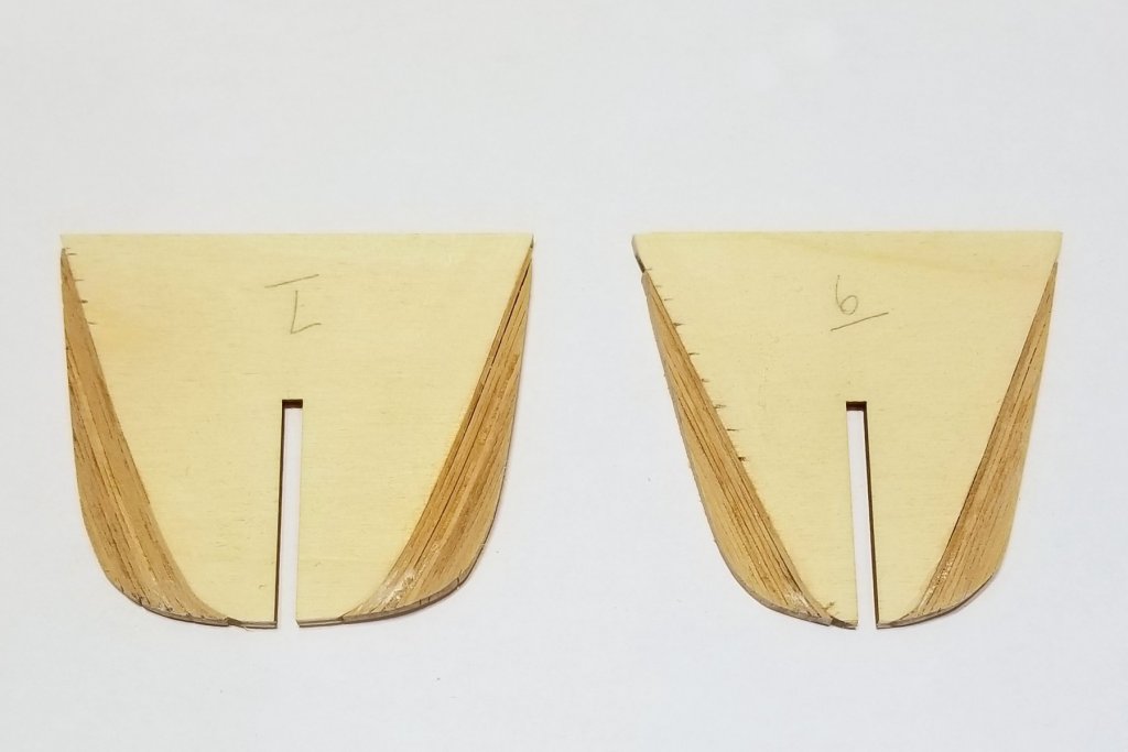
To Greg and Popeye's comments: when I started this approach I thought I'd be in for a very long slog, as you both have expected. But as it turns out, using my steamer and doing two at a time (so the glue for one strip dries on one bulkhead while working on the other) makes the work go fairly quickly. Here's a pic of bulkheads 6 and 7. Now I just have 3, 4 and 5, which have decreasing amounts of fill going from 5 to 3, so those should go fairly fast as well. As this will end up, to my surprise it's no more time than I'd have spent sourcing 4mm ply, buying the saw I don't have, and then shaping the pieces with all of the cutouts. Regards, David
- 168 replies
-
- 10
-
-
Don: Thanks. I think I'll do that just to be safe. But they feel pretty strong. They are walnut (hardwood), and each layer is glued with CA gel, so the whole thing feels pretty solid. But I'd hate to discover the opposite during fairing, so the wood support is a great idea. Regards, David
-
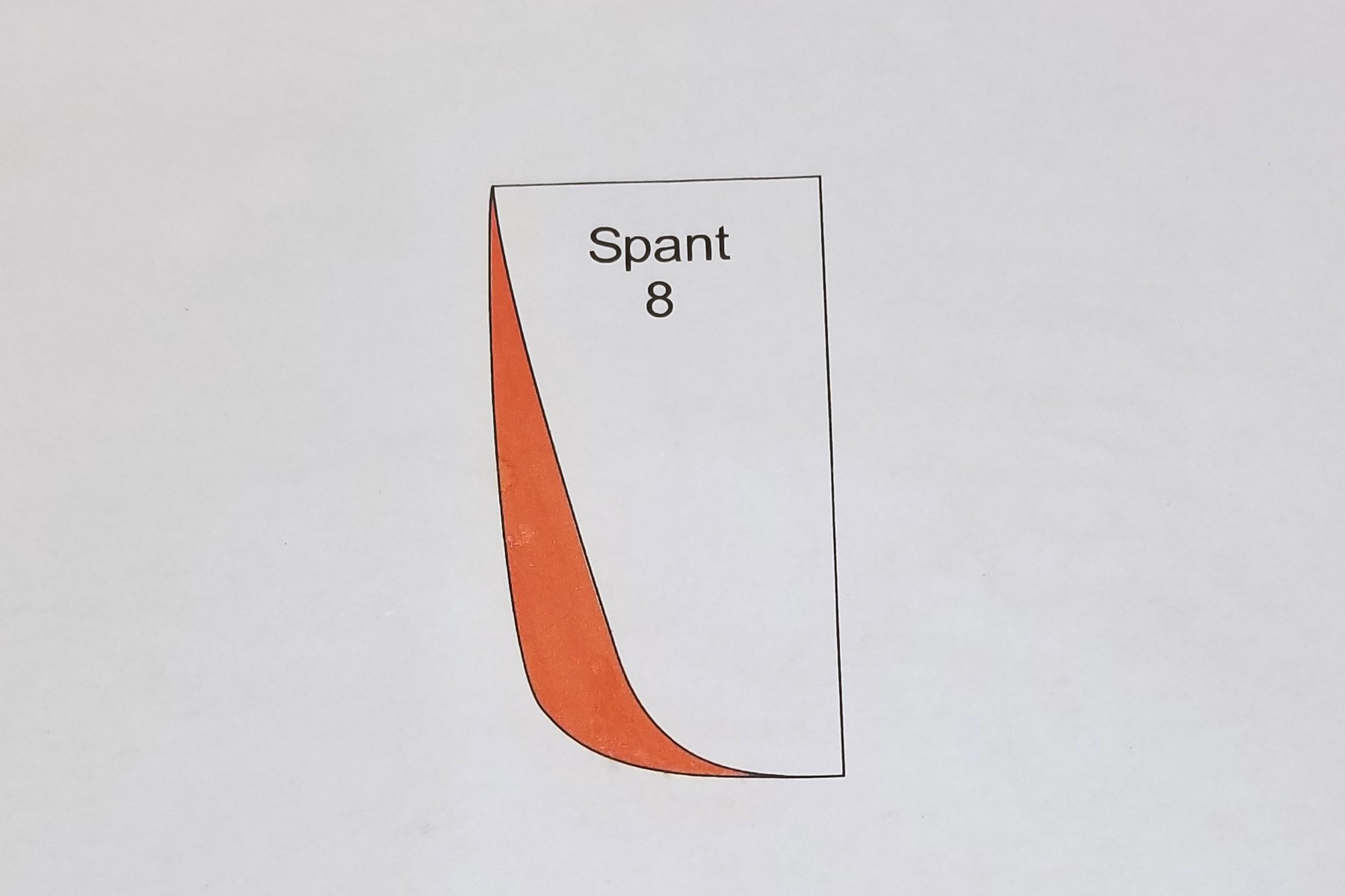
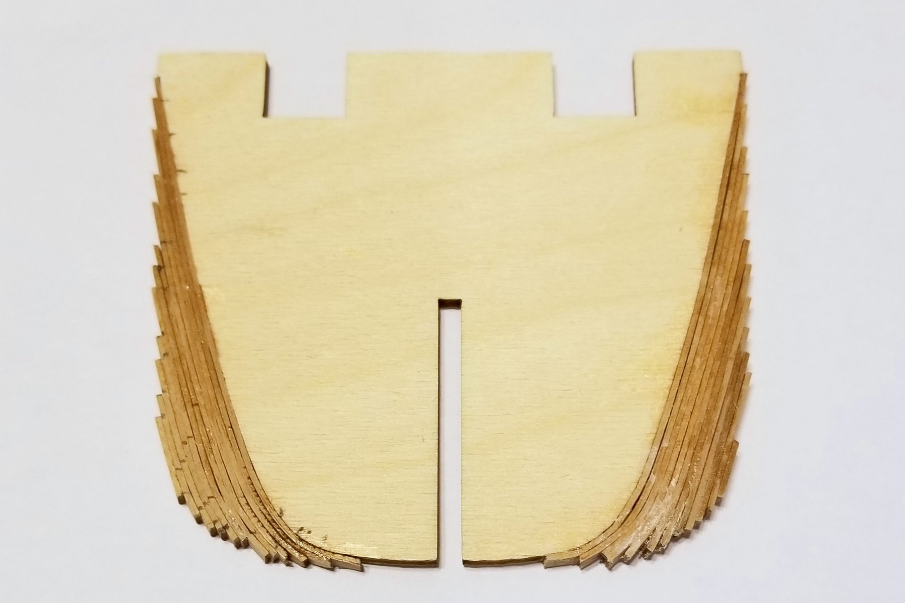
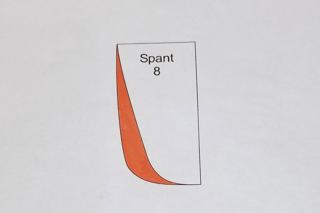
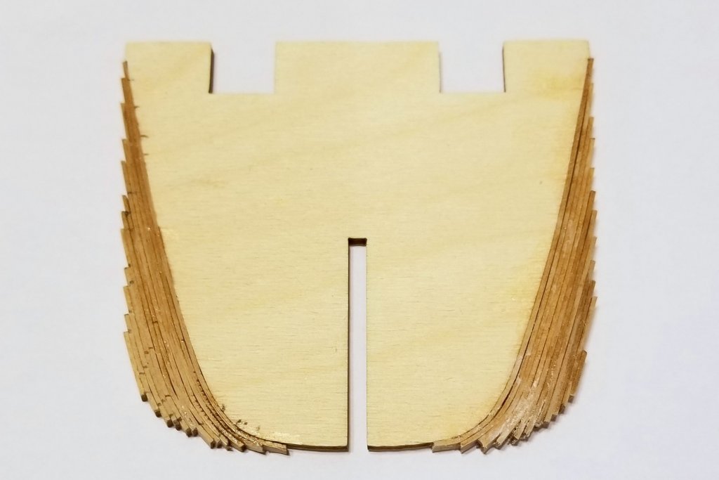
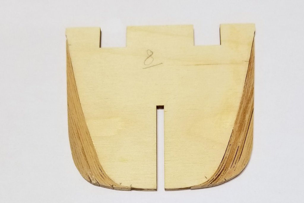
I've now had a chance to look at and deal with the bow bulkheads. First off, I want to repeat kudos, high fives and thanks to lgfrench, who forwarded me the post on this issue, and also the template showing how the bulkheads need to be adjusted. I started with the template. When printed the diagrams aren't to scale, so I ran it through Photoshop to isolate an individual bulkhead template (in this case, bulkhead #8 which has been my test case). I then printed that at different sizes until I got one where the "kit bulkhead" outline in white matched the actual bulkhead in hand. (see picture below). I don't have a jigsaw -- not even a coping saw -- and I don't have any spare 4mm plywood, but what I do have is a lot of leftover wood strip from previous models -- including a supply of 4mm wide walnut strip. So I decided to take the approach of laminating the strips onto the bulkhead and then each other, and the rough result of that is on the second picture. The third picture shows what it looks like when sanded down to match the red outline on the template. So that's one bulkhead -- and once I started working with my steamer and came up the learning curve things moved along more quickly. So now 5 more to go. Regards, David
-
lgfrench: Thanks very much for the bulkhead info. I will look carefully and get back to you when I get there. Has anyone looked at whether the solution is to do more fairing of the previous bulkheads? Regards, David
-
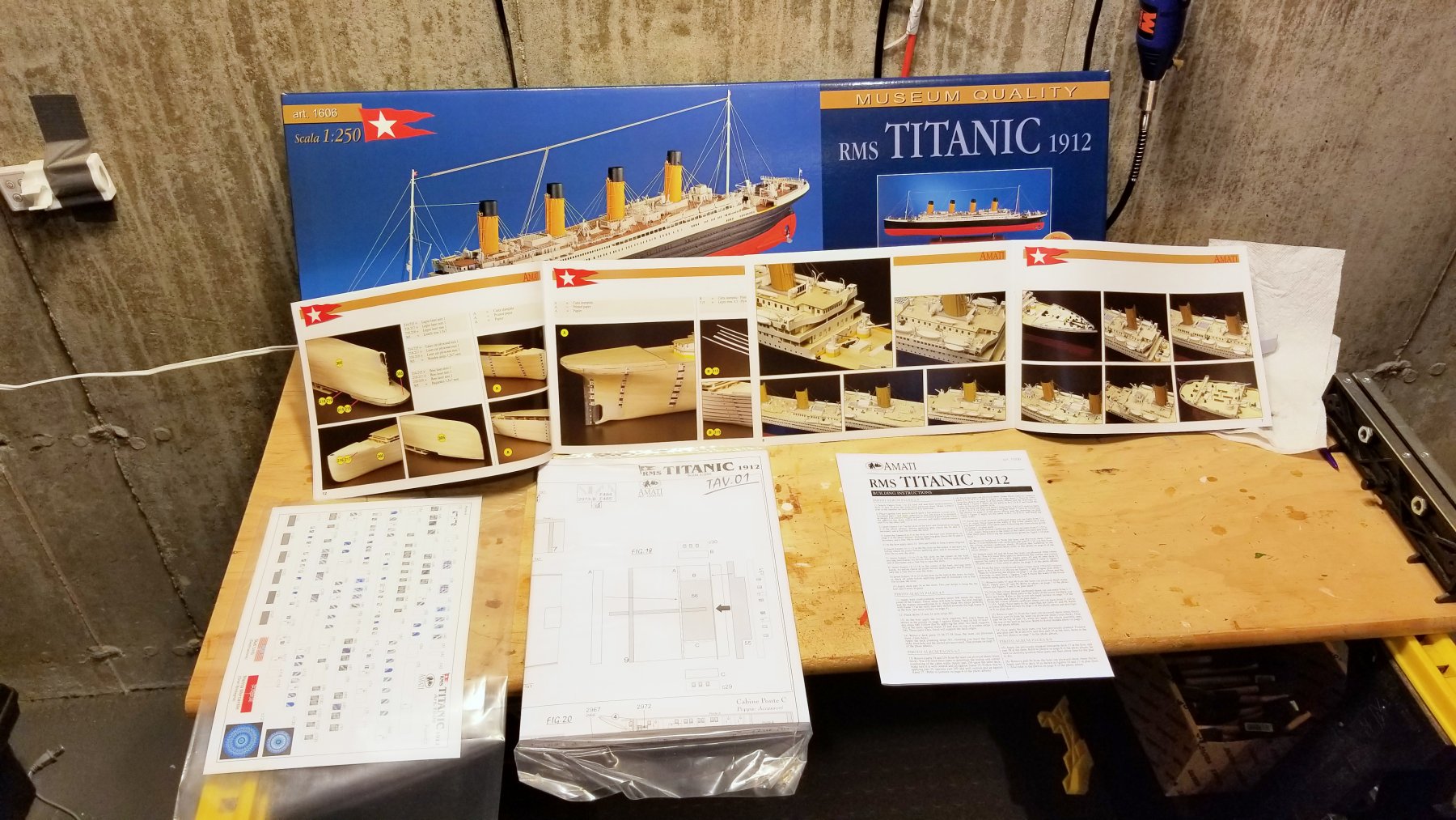
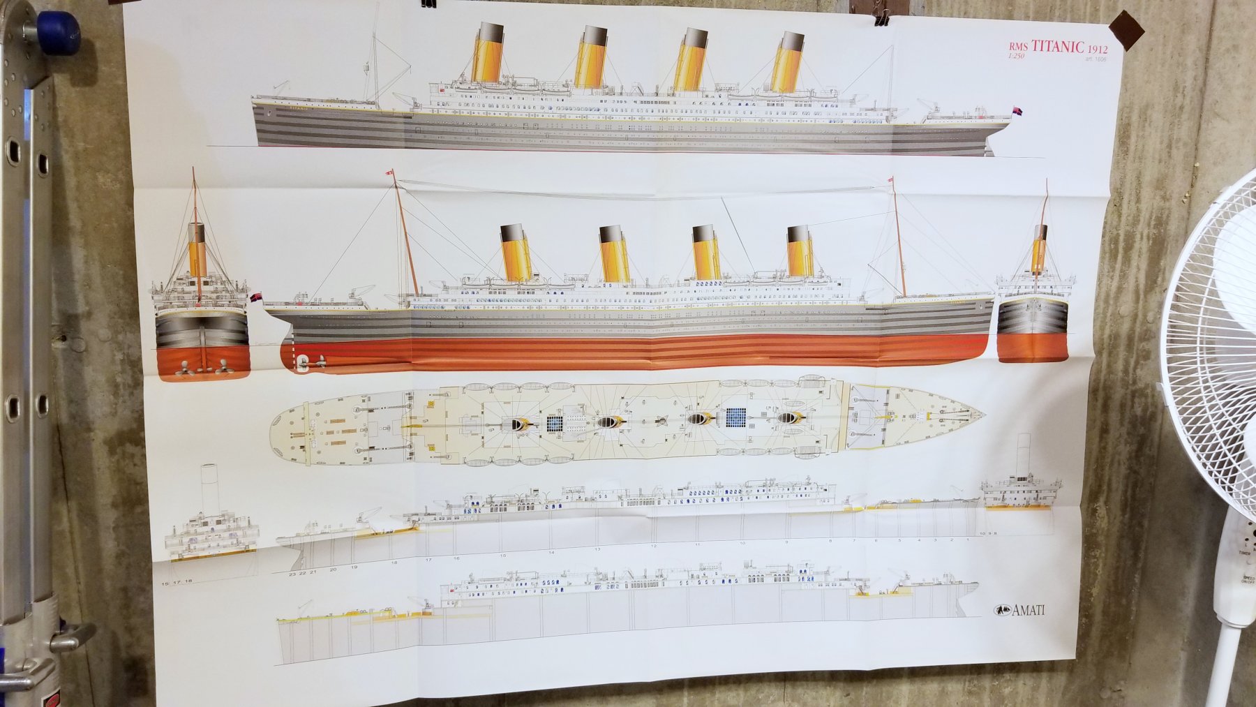
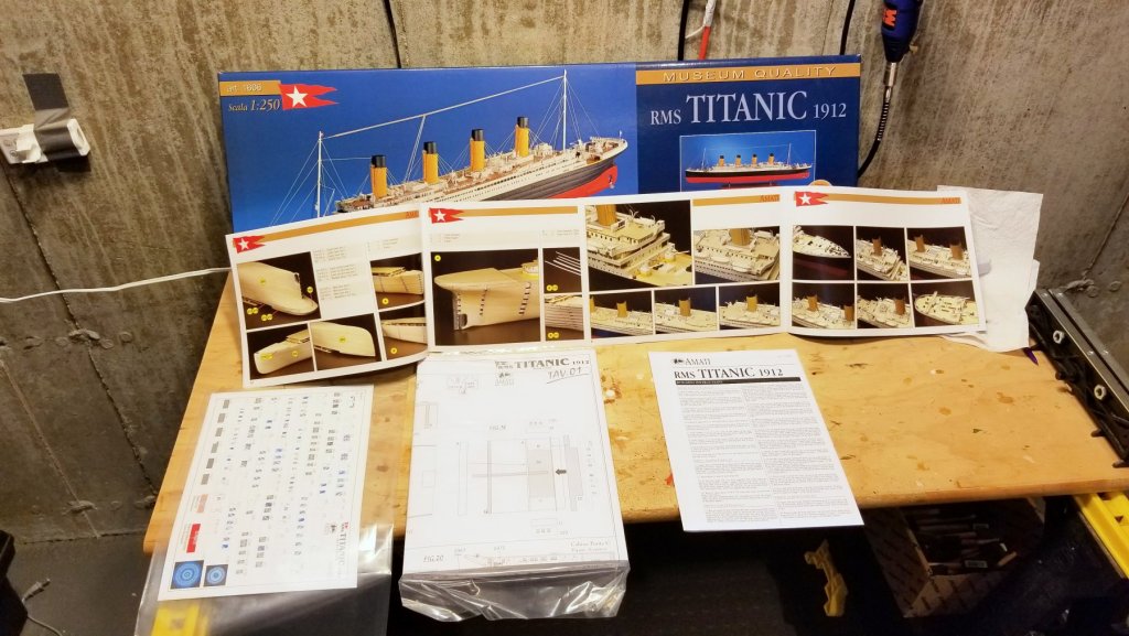
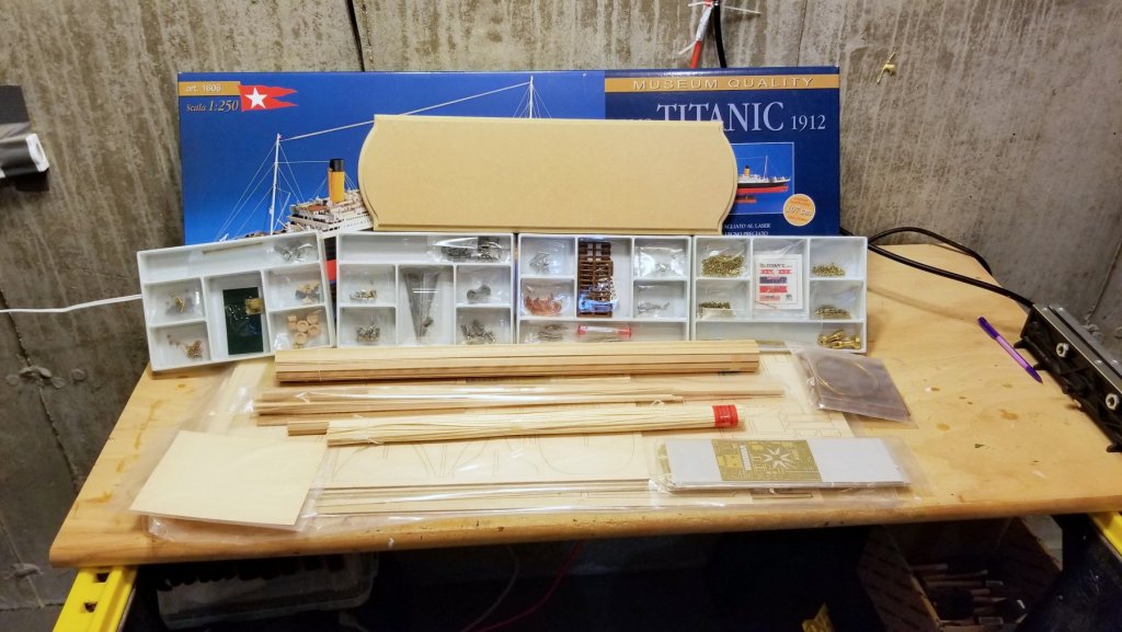
Well I'm back from vacation, and it's time to dig into the Titanic, which I've had in my sights since I started modeling a couple of years ago. Here's the "What's In the Box" post: Manual with picture books plus lots of plan sheets A large wall poster of the entire model The stuff: plywood laser cut sheets, parts, wood strip, etc. Just on the surface, this looks like it's going to be a different kind of build from the Amati ships or other boats I've built. Because there isn't a complete log that I can find, I'll try to post frequently as I go. Regards, David

-
Happy (early) birthday, Chris! She looks great. Regards, David
-
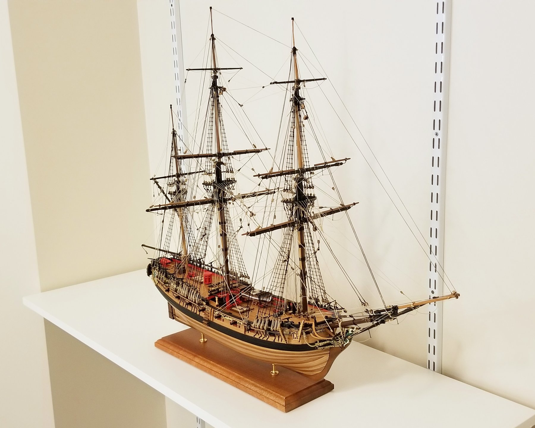
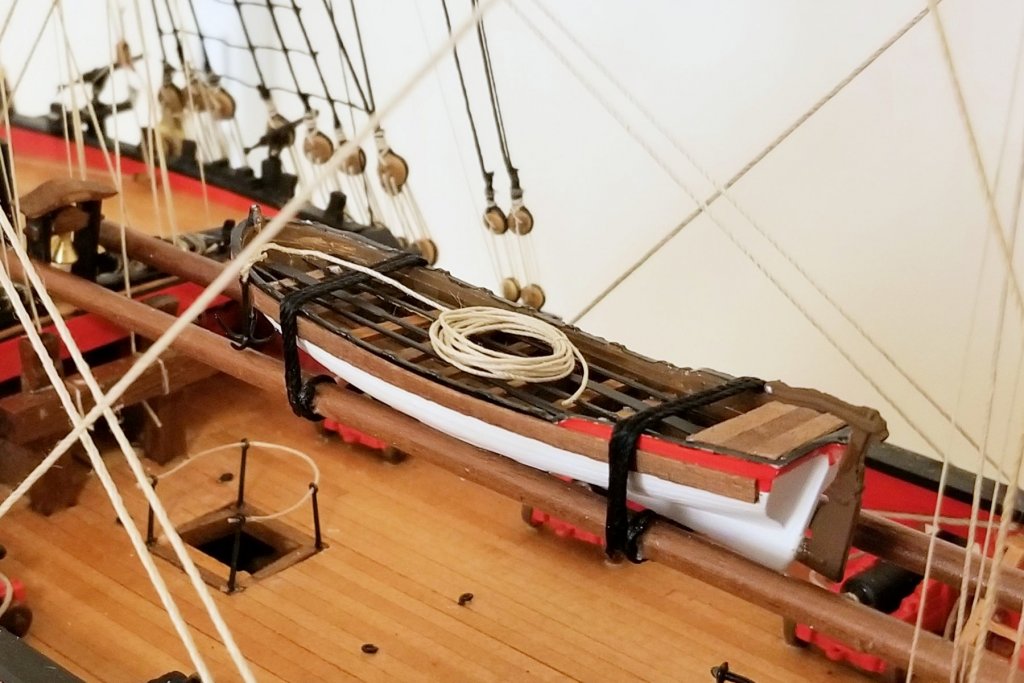
FLY IS COMPLETED. I finished the H.M.S. Fly today -- competed pics are in the Completed Kits Gallery. Just a couple of samples here. I wanted to see what the lifeboat from the upgrade would look like, so I built it and liked it, so installed it on the ship. I made some mods to it, including using real wood planks down the side at the gunwales, vs. paint. A couple of kit build notes from my most recent work: I added some fine thread braces to the stays the crow's feet are attached to, to keep the crow's feet tight. Important as the stays are pulled up by the rigging and need some counter-balance. I ran out of 3mm and 5mm blocks, and 3mm deadeyes. Fortunately, I had leftovers (plenty) from the Amati Revenge kit, so I was OK, but a caution to other builders. I didn't lose more than 2-3 of each on the floor. Now a break from kit building while my wife and I go on a Greek Islands cruise. When I return in late September, I'm going to tackle the Amati Titanic, and I'll create a detailed build log for that as I don't see much on this site. Regards, and Happy Labor Day to the Americans, David

- 126 replies
-
- 19
-
-
- fly
- victory models
- (and 1 more)
-
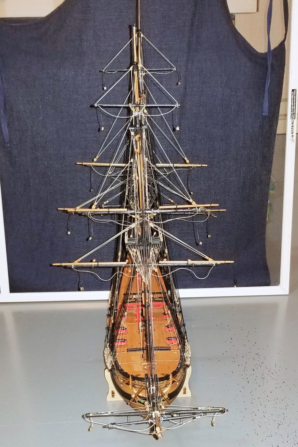
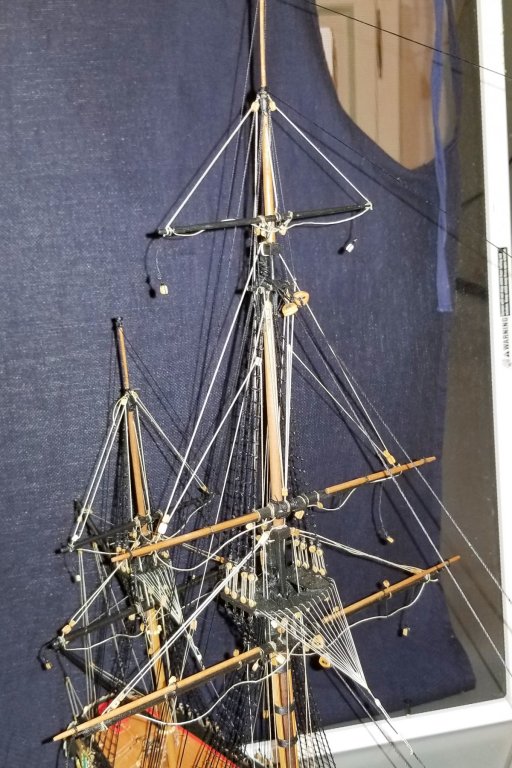
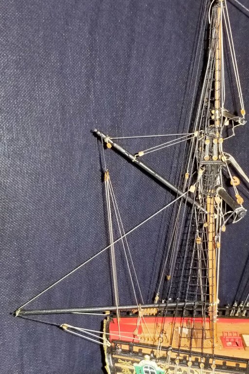
The yard lifts are now up, so from here on to the final stage of rigging, then mounting & done. Regards, David

- 126 replies
-
- 8
-
-
- fly
- victory models
- (and 1 more)
-
Looks wonderful, Chris. The quality of your work is astonishing. Regards, David
-
Chris: Thanks very much. Yes, I do have the next build planned. I'm going to do the Amati Titanic, which I have on the shelf waiting. Regards, David
- 126 replies
-
- 1
-
-
- fly
- victory models
- (and 1 more)