drobinson02199
-
Posts
1,079 -
Joined
-
Last visited
Content Type
Profiles
Forums
Gallery
Events
Everything posted by drobinson02199
-
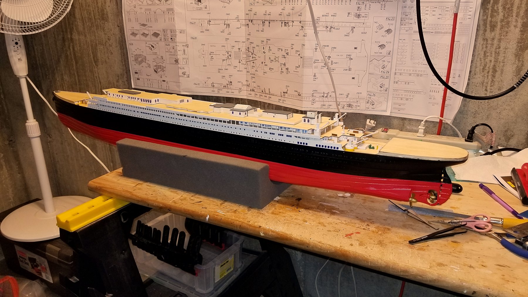
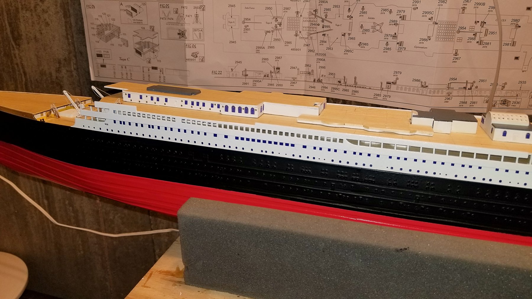
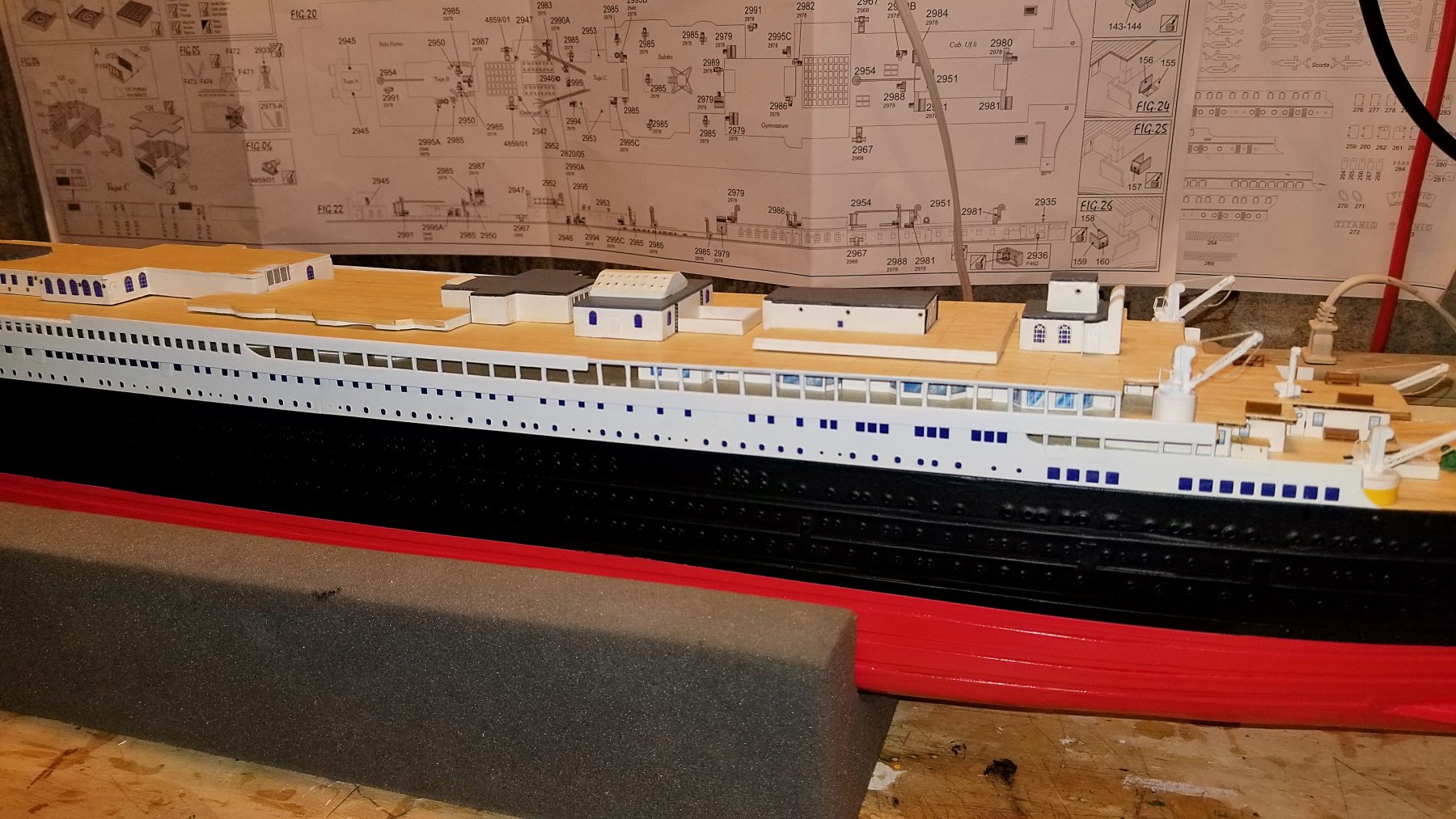
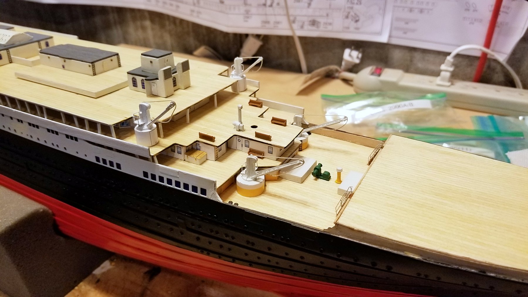
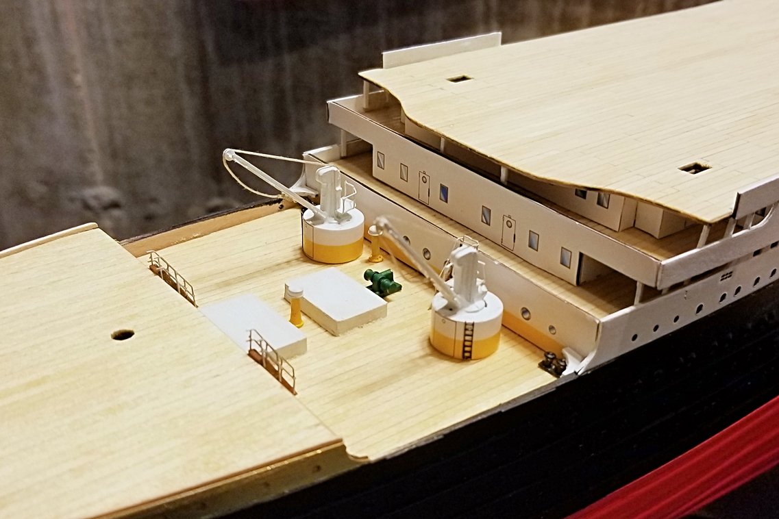
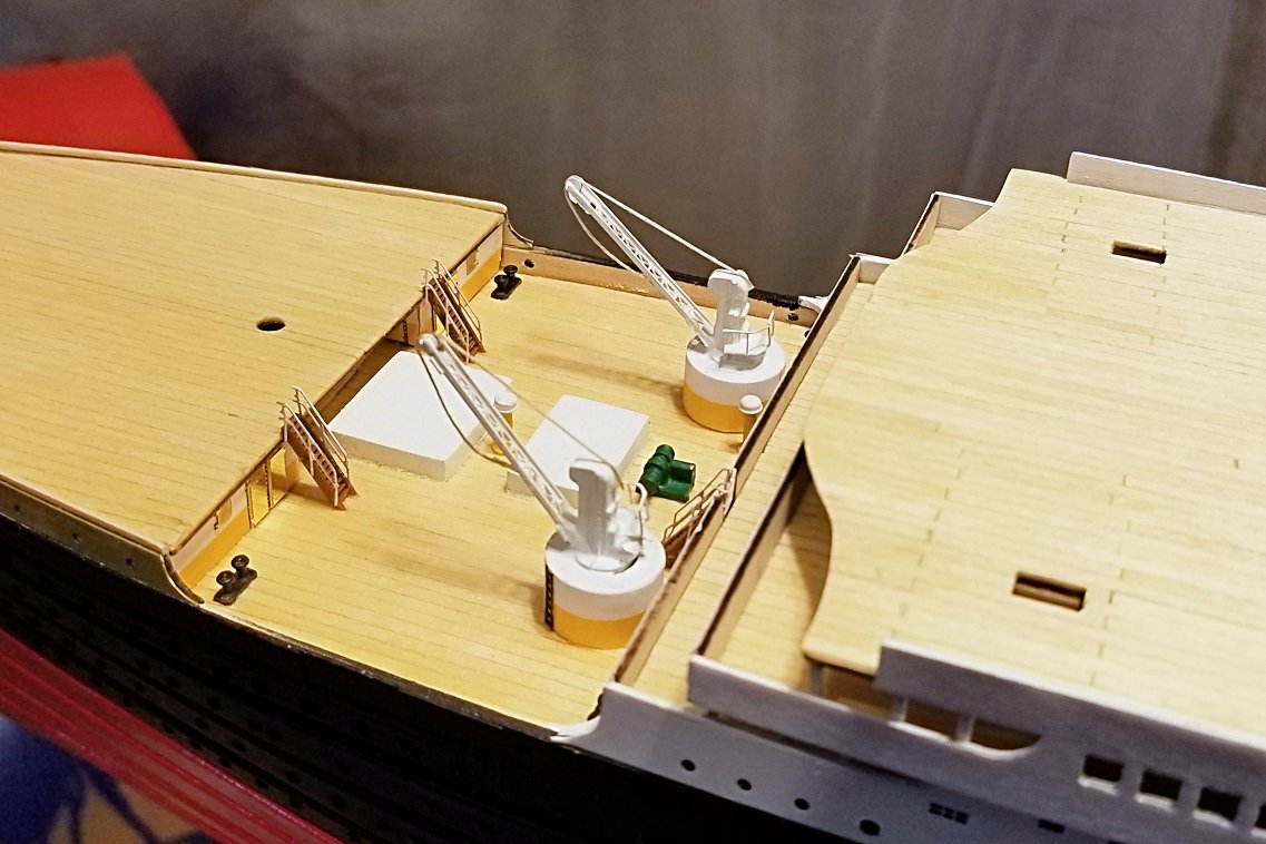
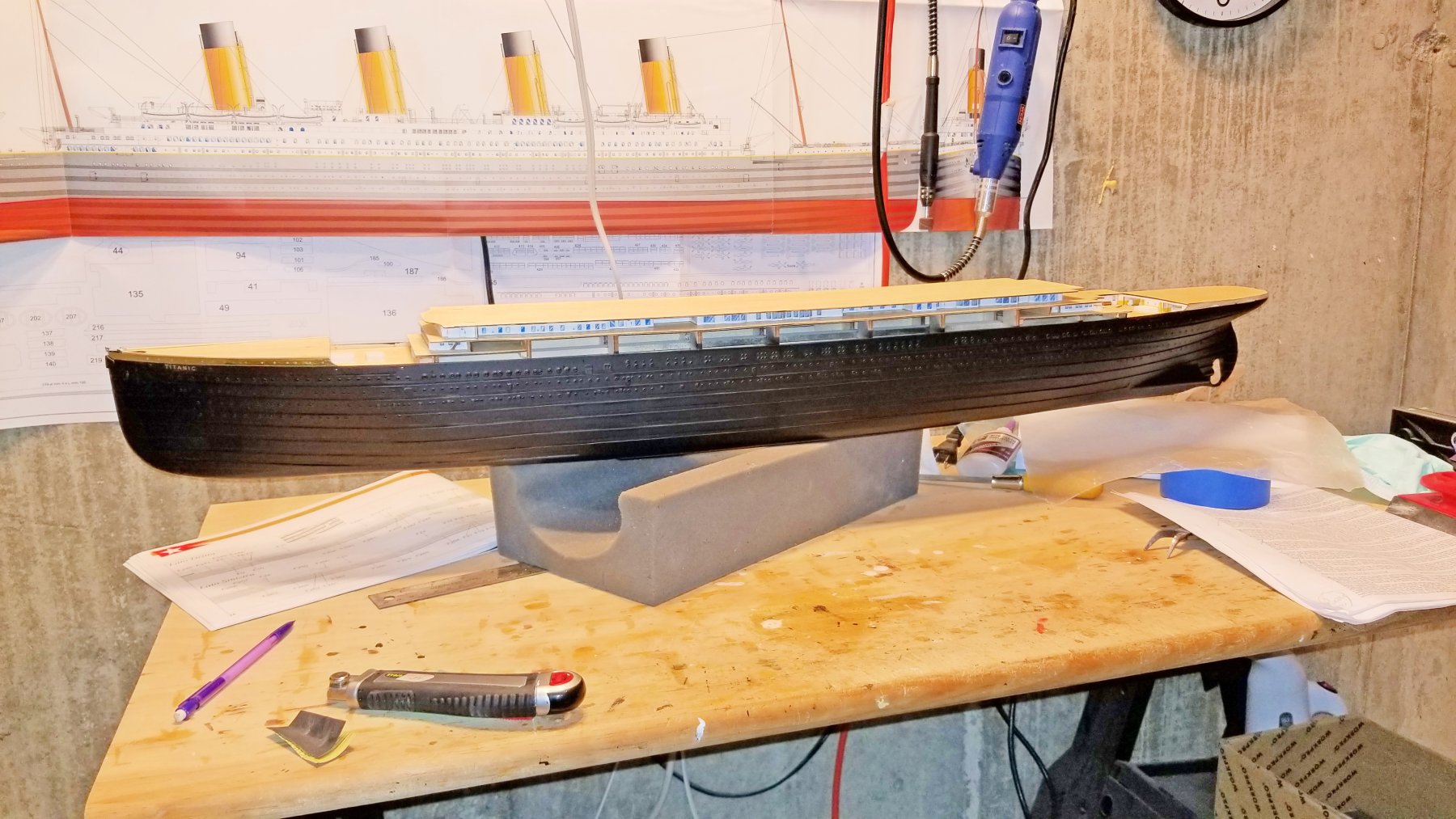
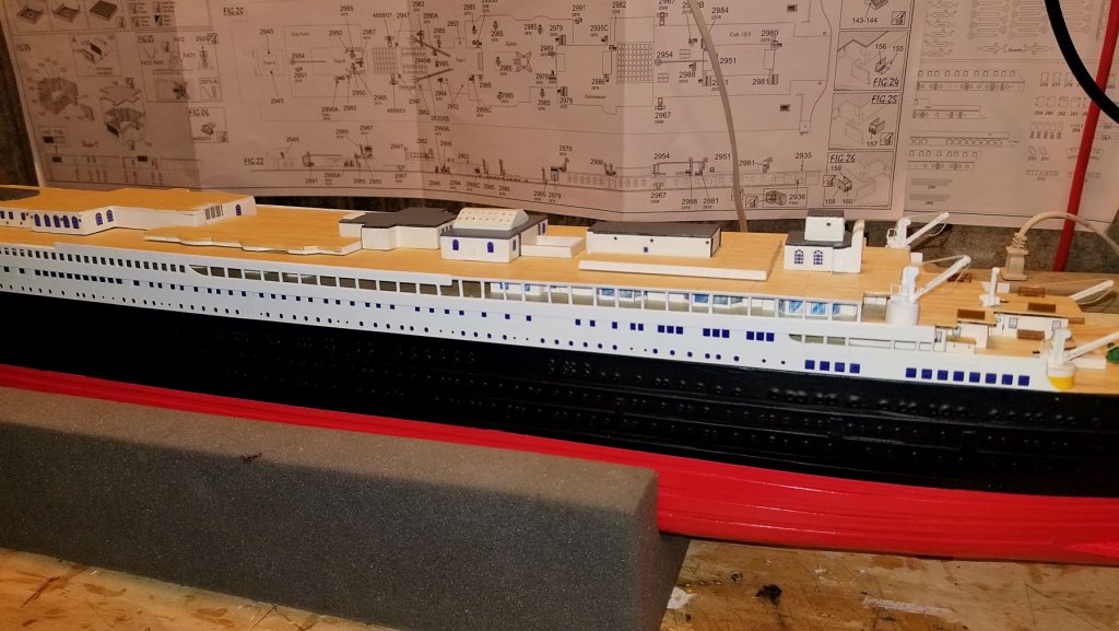
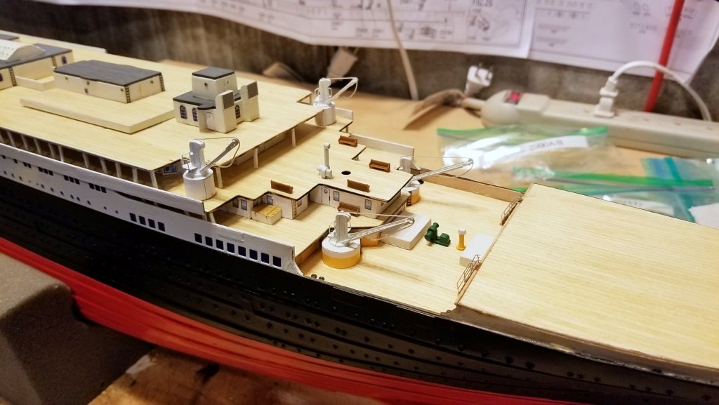
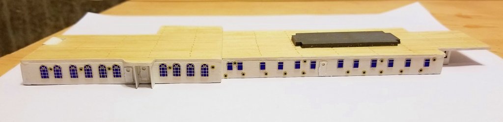
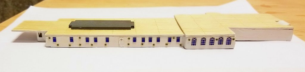
 Cabins now installed on the deck; cranes and detail installed near the stern. Regards, David
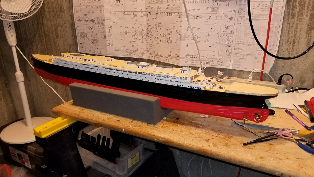

- 168 replies
-
- 14
-

-
Thanks, Popeye. The red hull color I used looks pretty similar to the photos of the Amati model on the box and in the manual. Re the other colors -- my yellow matches the pre-printed yellow stripe, and I am pretty good on the other colors (green, gray, black and white). As might be apparent, I'm not a total stickler for complete historical accuracy. 🙈 🙉 🙊 Regards, David
-
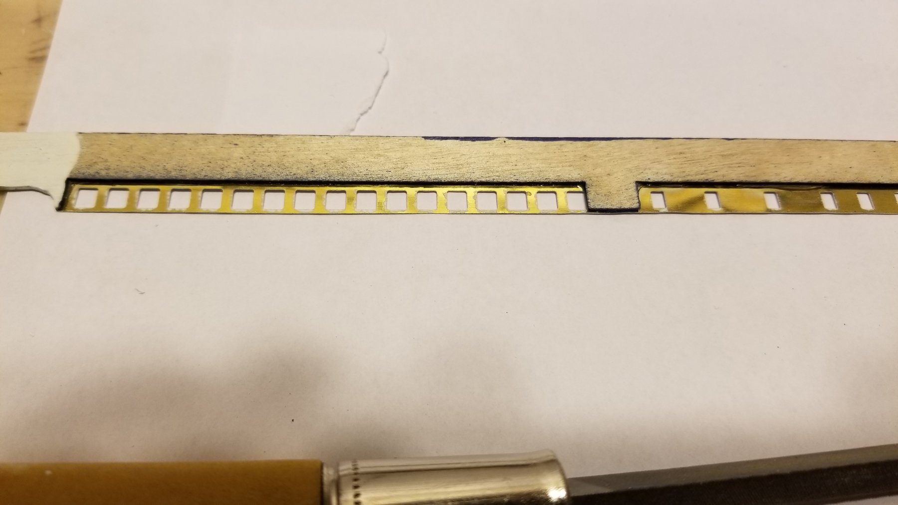
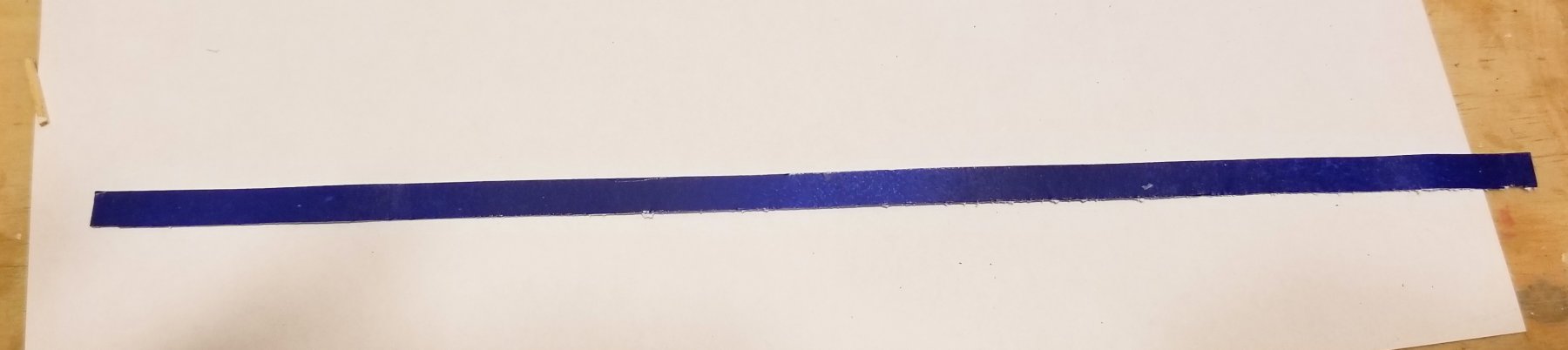
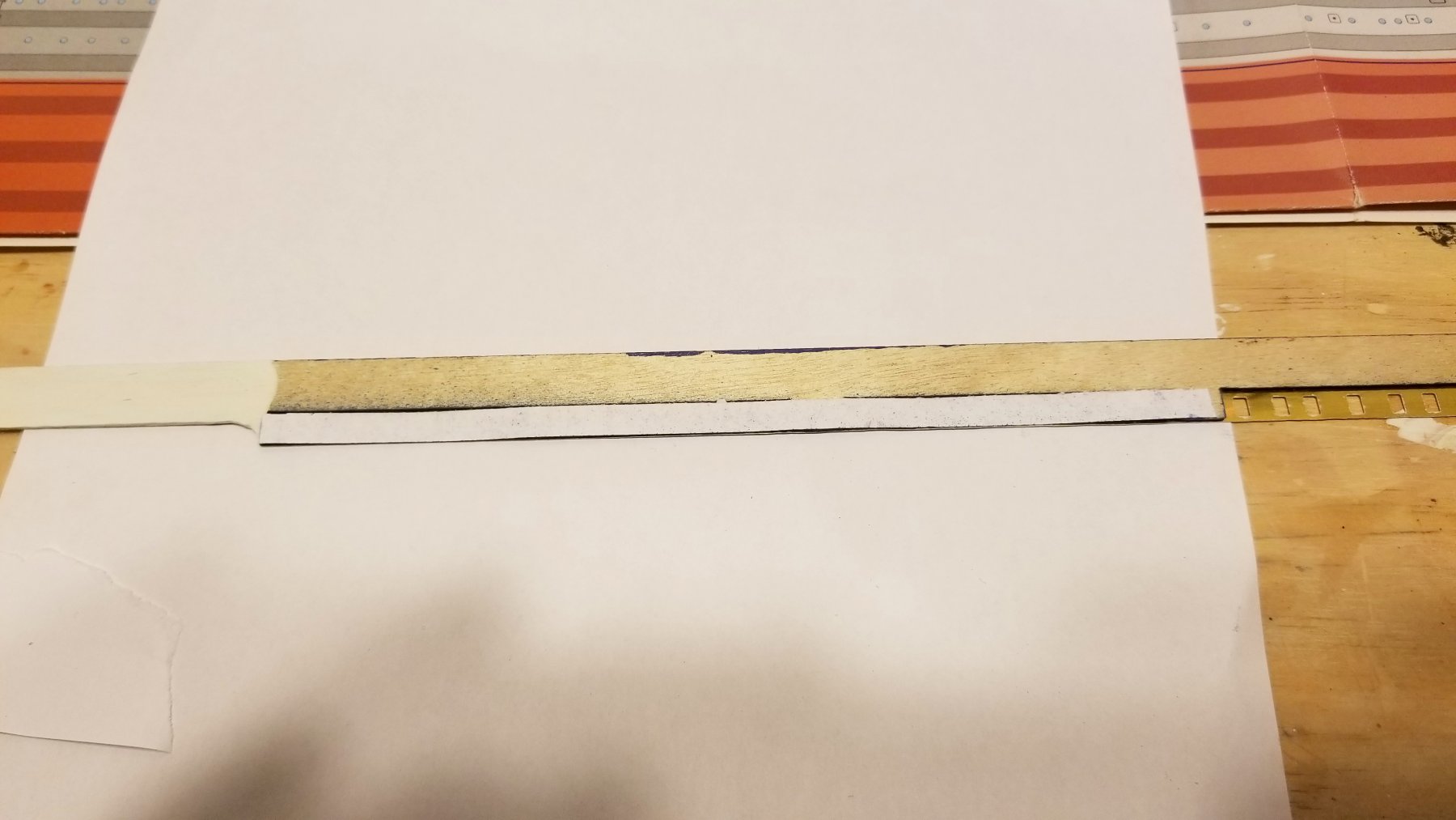
More on the sides. The photo-etched brass sides mount on thin plywood, and the instructions suggest painting that black or blue to give background and depth to the windows. So I did -- used blue. But as you can see in the first two pics below, the ply backing doesn't come up to most of the windows. So you have a nice blue background for the small portholes at the bottom, and the larger windows would be uncovered and black -- except where one or two vertical frames show through, which makes it look unfinished. So when I sprayed the plywood, I also sprayed some white paper. I'll cut that into strips and attach to the back -- the first one is shown below, and the result for that first strip in the last pic compared to the uncovered windows. This works because those vertical attachment points don't line up with the frames, so I can glue the paper to them without worrying that I'm weakening an attachment point for the bulkhead. Those vertical points are part of attaching the brass to the wood. Regards, David

-
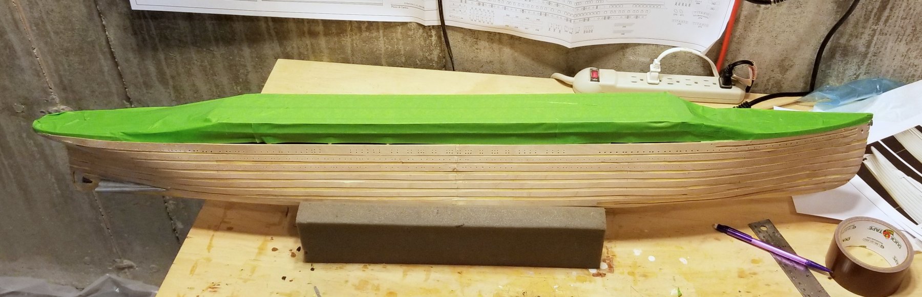
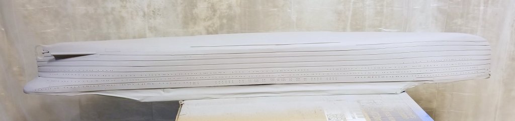
Before painting the bottom of the hull red, I need to install the sides. As much care as I took to leave enough room when building the structure, when I went to dry-fit the photo-etched sides and their backing, they didn't fit -- just. So I had to grind down the underside of the deck, and also grind off some of the PE siding, and now it fits -- tightly. This has to be painted before installation. Regards, David
-
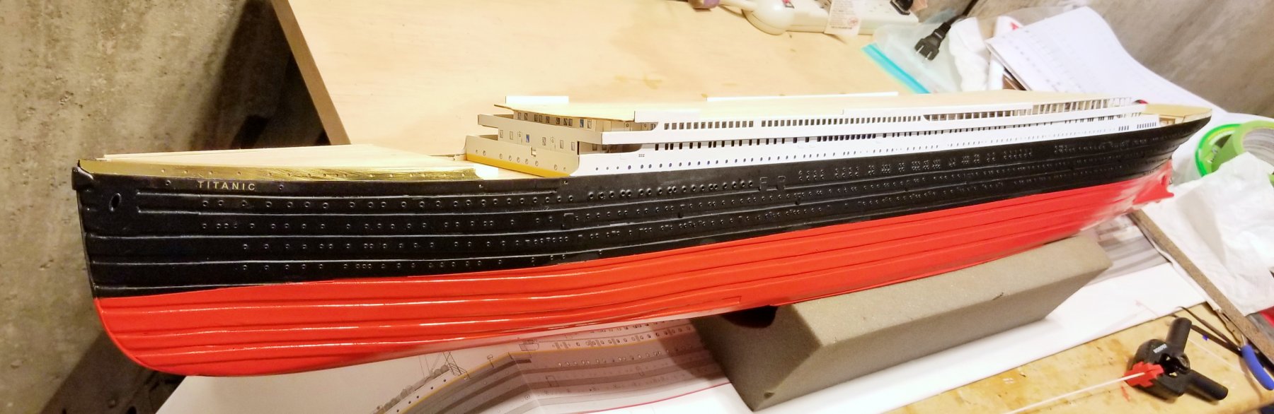
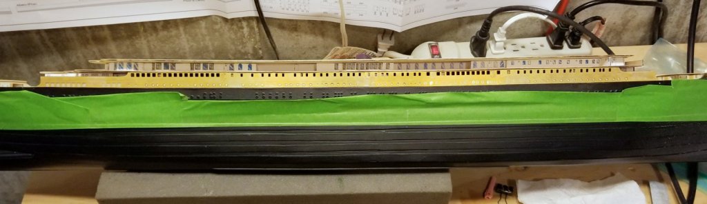
The hull is now painted black. I found that when I went to sand the paint off the nameplate letters, the 2 coats of spray enamel were too thick, and I ended up taking some paint off the background and surrounding areas. So I repainted the nameplates with acrylic (brush), and that sanded off nicely. It's a flat black on the hull -- the flash just makes it look a bit glossy. Regards, David


- 168 replies
-
- 12
-
-
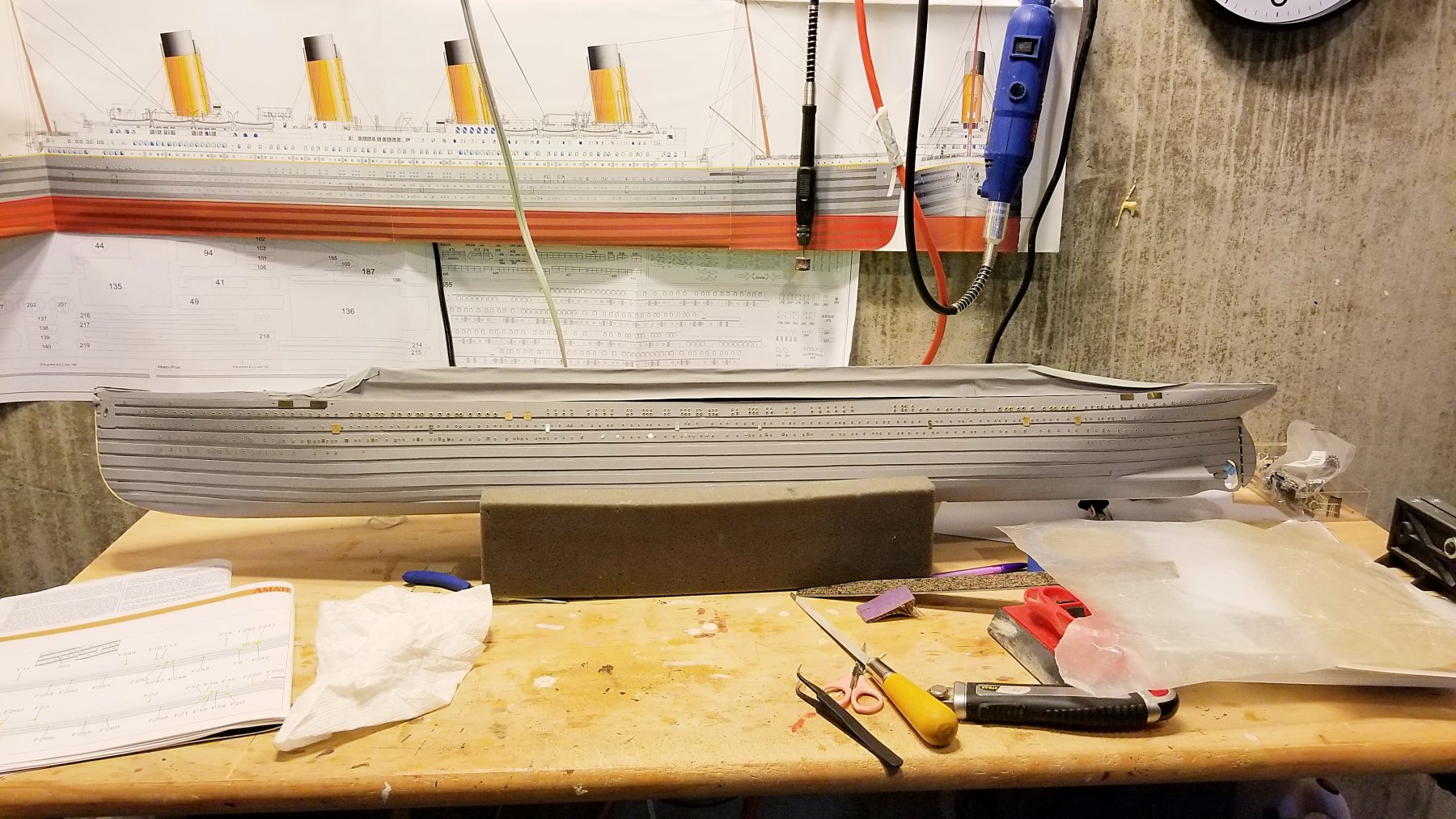
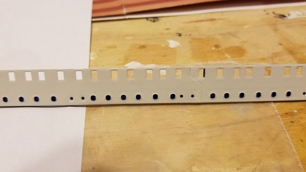
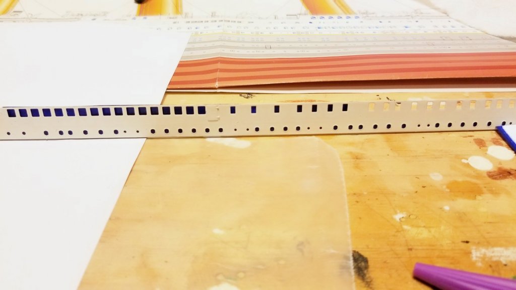
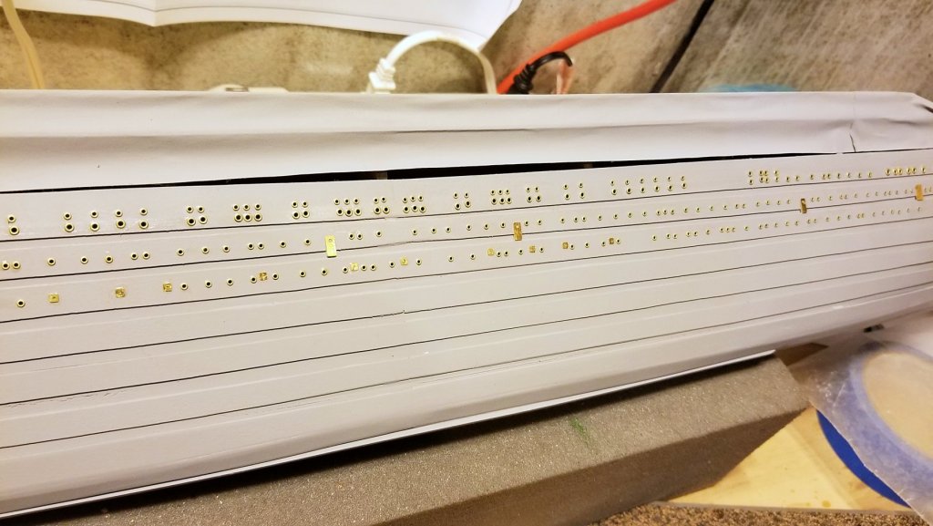
I've installed all of the portholes, doors and scuppers on one side. All of this brass detail will be painted over in black. There are a LOT of portholes to install! The Titanic nameplates aren't on yet. Regards, David
- 168 replies
-
- 10
-
-
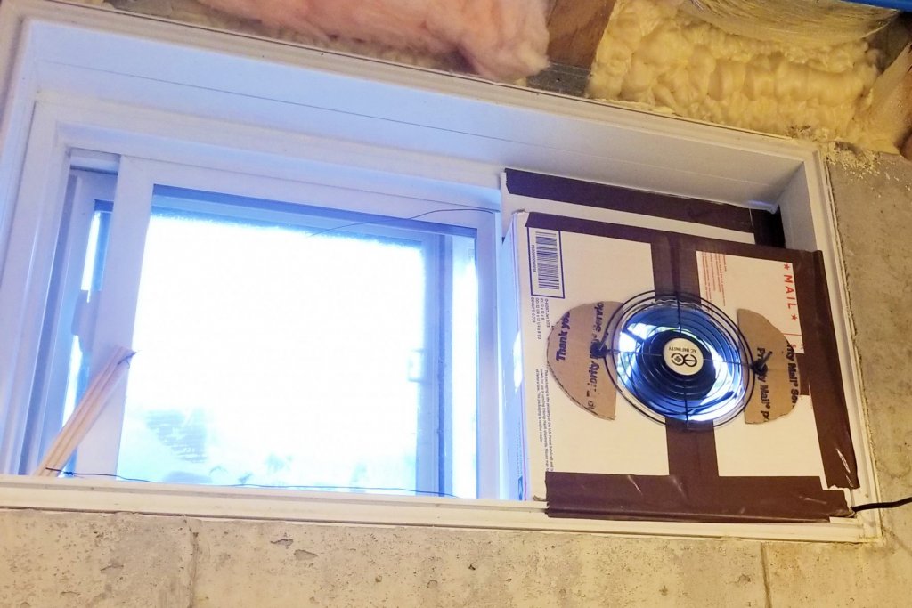
Re my earlier comment on an exhaust fan -- here's a picture of the $35 fan I got on Amazon, mounted in a 12x12 shipping box, which works fine. I attached a handle to the sliding basement window so that I can pull it open and close it again. Fan moves 220 CFM. I just added the second coat of primer and this little fan works really well. There are fumes at the start, but they get dramatically reduced after a few minutes. Regards, David
-
Popeye: I see you're in Manchester, which is even colder than here in Boston. FYI, the little fan I ordered was $35 on Amazon. I plan to just open one of the small basement window and put it in as needed. Regards, David
-
Here's the hull, taped for painting, and after the first primer coat. It's winter here, and while I've painted my other models in the garage in milder weather, my basement workroom isn't well-ventilated, and the fumes are pretty strong. So I ordered a small but high CFM flow exhaust fan that I can put into a window. It comes Thursday, and no more painting until it's in. Regards, David

-
I've now decorated the large cabin structure with windows and vents. Positioning the windows to keep them aligned was a bear, even with tape as a guide, because I used CA gel and it sets fast so I had to align and get them vertical quickly. PVA glue would allow more adjustment time, but I was concerned that the windows might come off either as the model ages, or with any side contact. I think the next step is hull painting. Regards, David
-
I figured out how I'm going to keep the windows aligned. In the first picture, I have made vertical marks representing the center of the windows, by holding the structure up to the plan drawing. I then measured horizontal marks under them at 2.5mm above the bottom. I then taped just under the marks to give me a 2mm height above the bottom. The tape gives me vertical alignment, and the vertical marks allow me to place the windows properly horizontally. Picture 2 shows the work in progress, and picture 3 is the finished result. I now feel better about tackling the long cabin windows and having them come out looking good. Regards, David

-
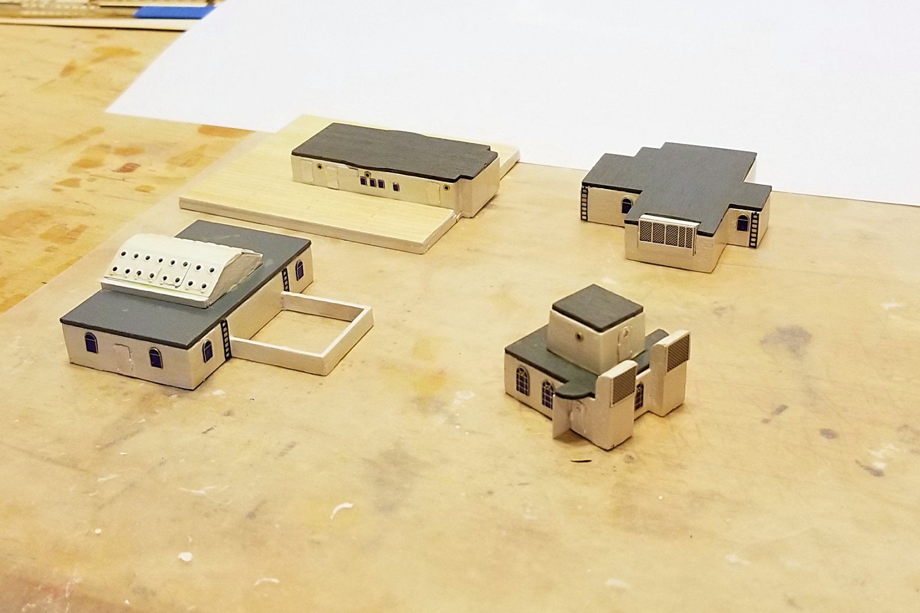
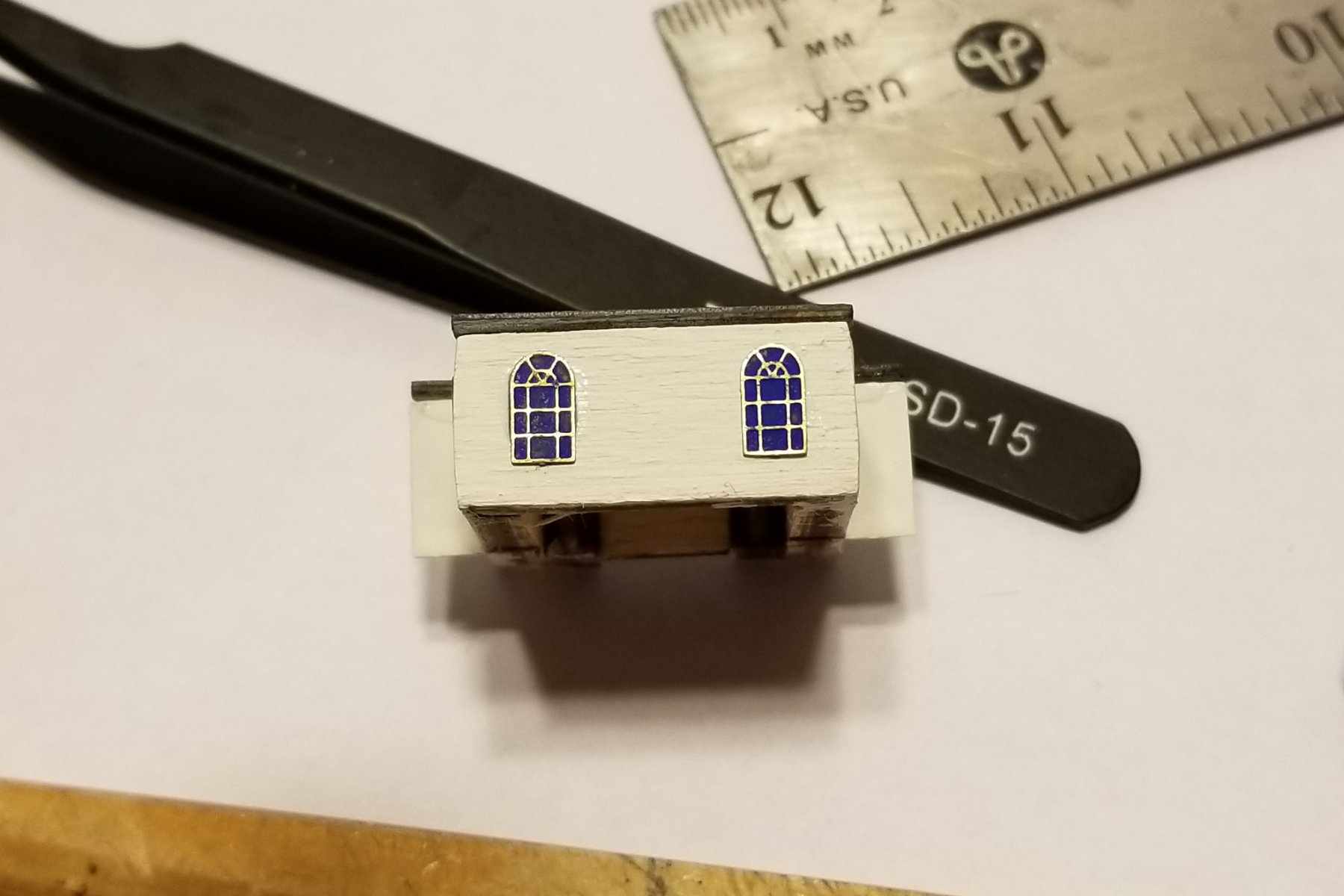
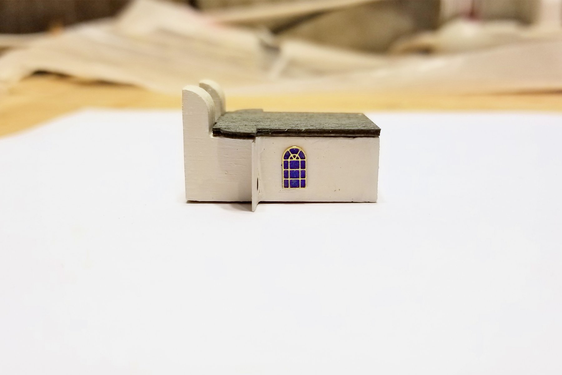
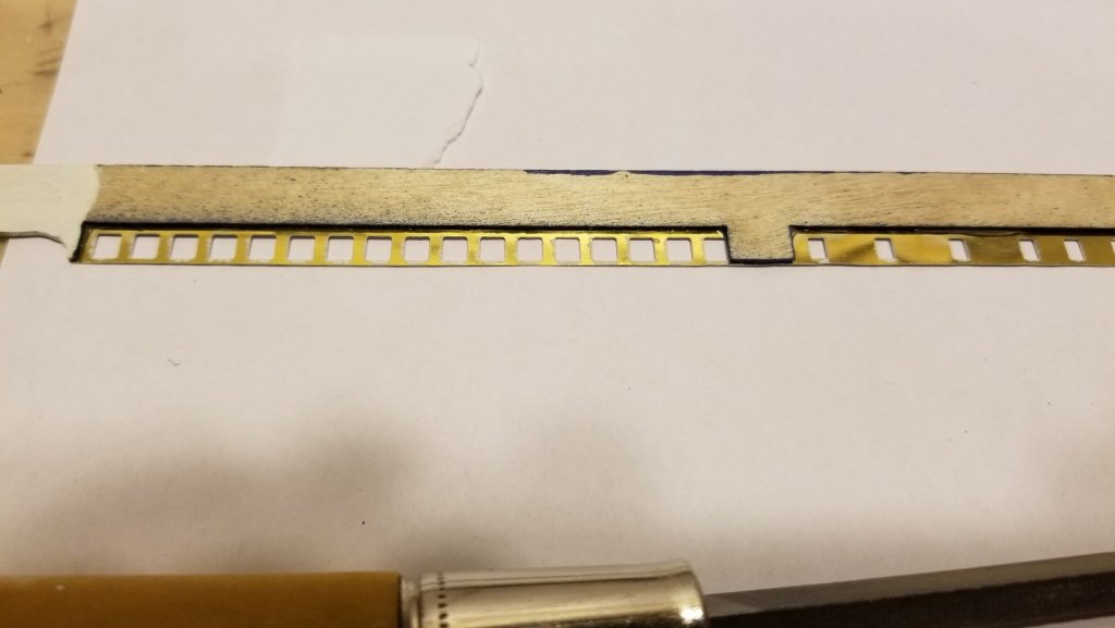
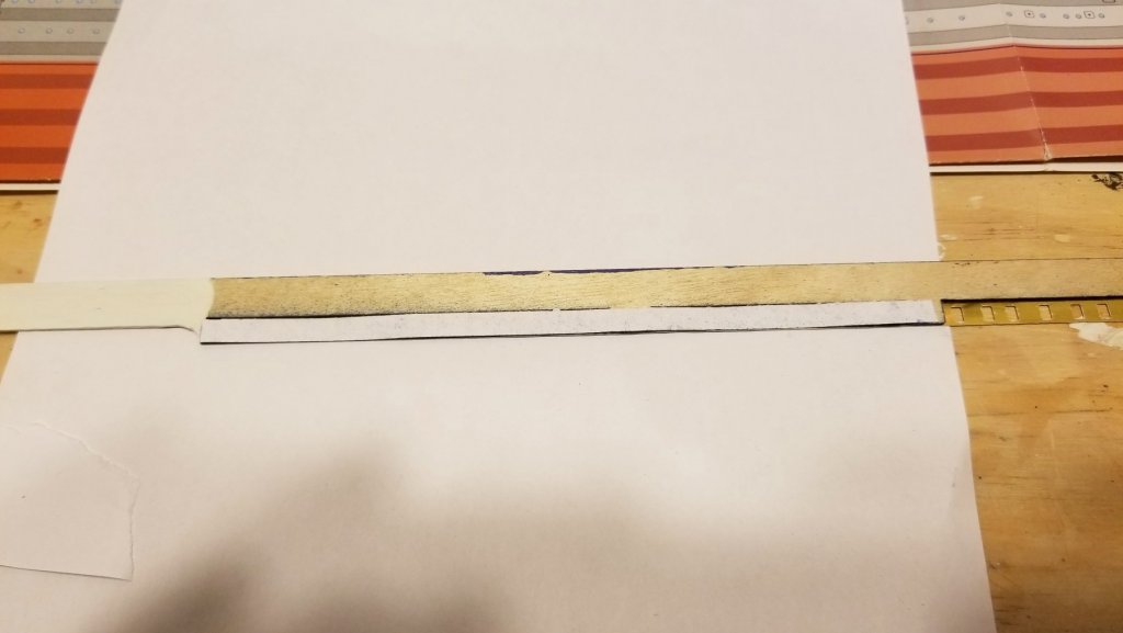
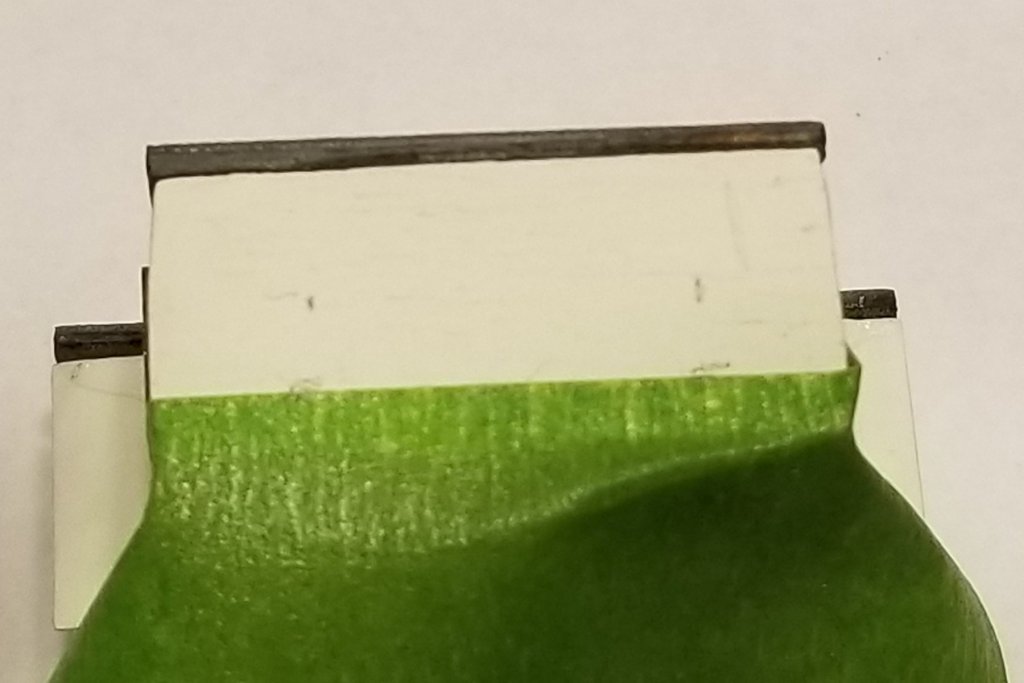
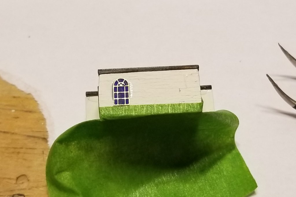
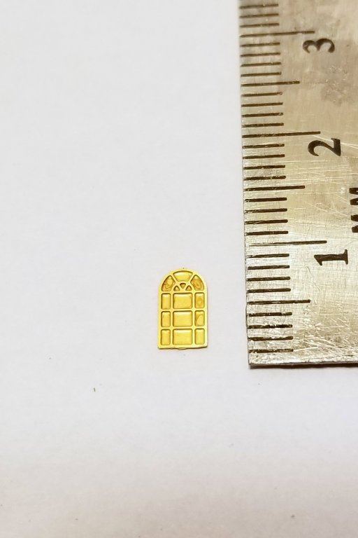
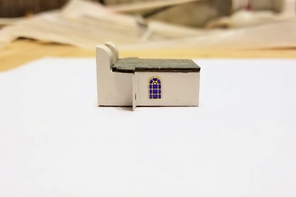
The last step in the instructions before painting the hull is to build the deckhouses, so I've done that (first picture). In the instructions, these aren't decorated and mounted onto the main structure until after hull painting, but I've decide to do it now as long as I'm in "small parts mode." The doors and windows at this level are individually mounted photo-etched brass, and if you look at the finished pictures, the windows show a bluish background similar to the printed ones on lower decks -- but they are solid PE brass (see second picture). I remembered a technique I learned on the Revenge, where I had to paint a large stern emblem with raised "frames" like the windows here. The technique was to paint the whole thing, and then when it dries sand it with fine paper, removing the paint from the frames but not the recessed panes. Tried it here and it worked like a charm. See third picture of my mounted test window. I used a cobalt blue. For the rest, I can gang paint them while still attached to the PE strip, and then I'll have to still individually sand them. The hard thing is going to be getting all of these perfectly aligned and spaced, particularly on the long cabin. Regards, David
-
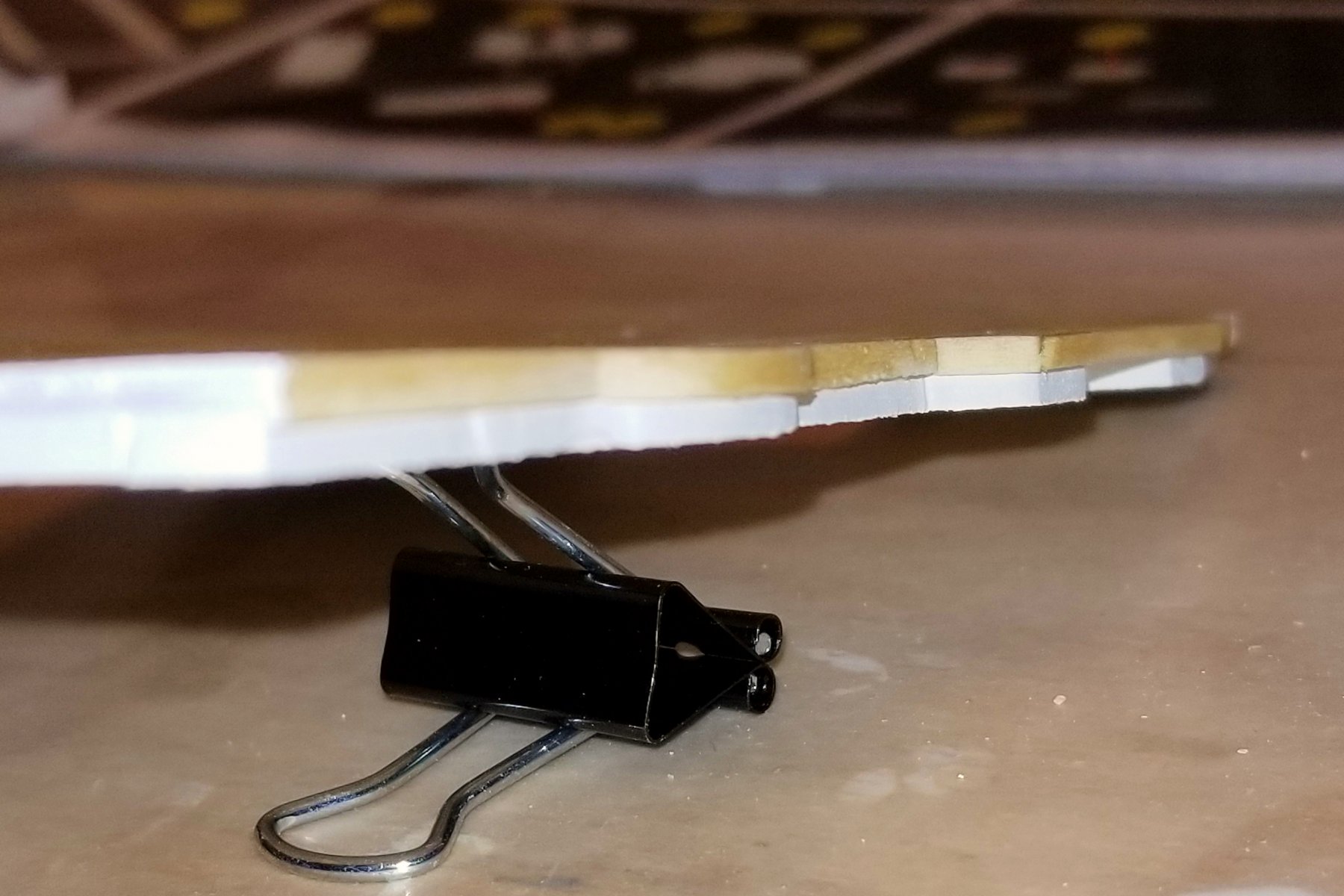
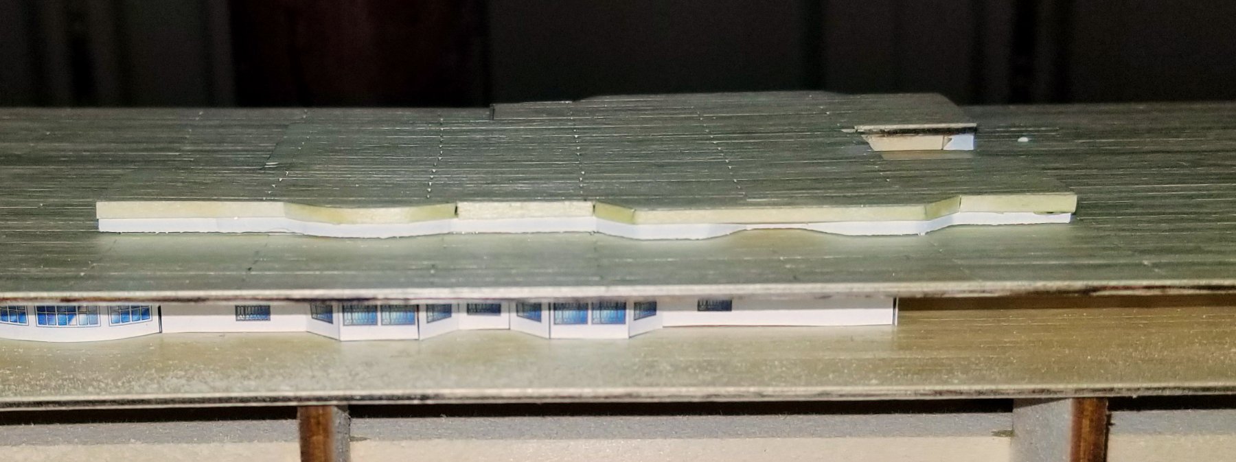
In the "not so fast" and "too clever by half" departments, I've now figured out that my clever solution above wasn't all that clever. Pic 1 below shows what I missed -- the dark deck edge, that needs to be painted too. So back to masking and painting, which didn't turn out to be all that hard (Pics 2 and 3). One puzzler in the instructions and plans is that they show small windows on those thin white edges, but there's no indication of where they come from as there is with every other printed and etched part in the kit. So more searching plans and instructions -- and after about an hour I found the tiny windows -- attached to railings above. So those will need to be painted and glued on top of these painted areas, but I think painting these is needed as the fits won't necessarily be perfect. That leaves two issues. The first is the etched windows. In all the pics, they show a colored background "through the glass", which for etched windows is solid brass. So I think I'll have to use a technique I learned on the Revenge, which is to paint them carefully in something like a medium blue, and then use very fine sandpaper to remove paint from the muntins, which are raised from the background. This will be needed for all the other windows that will be mounted on other structures at this level. The other one is figuring out how to mount the window/railing assembly on the side of the deck shown in Pic 4 (blurry, but shows the point), which has an overhang on it. Not sure how to mount those strips. Either there will be room to bend the window part back, or I'll have to sand down the overhangs to create a flat side surface. That may be the best solution, but we'll see when I get to that point, which will have to be before I mount this deck part. There is zero guidance in the instructions or plans about this -- and it leaves me wondering why that overhang was specified in the first place. Regards, David


-
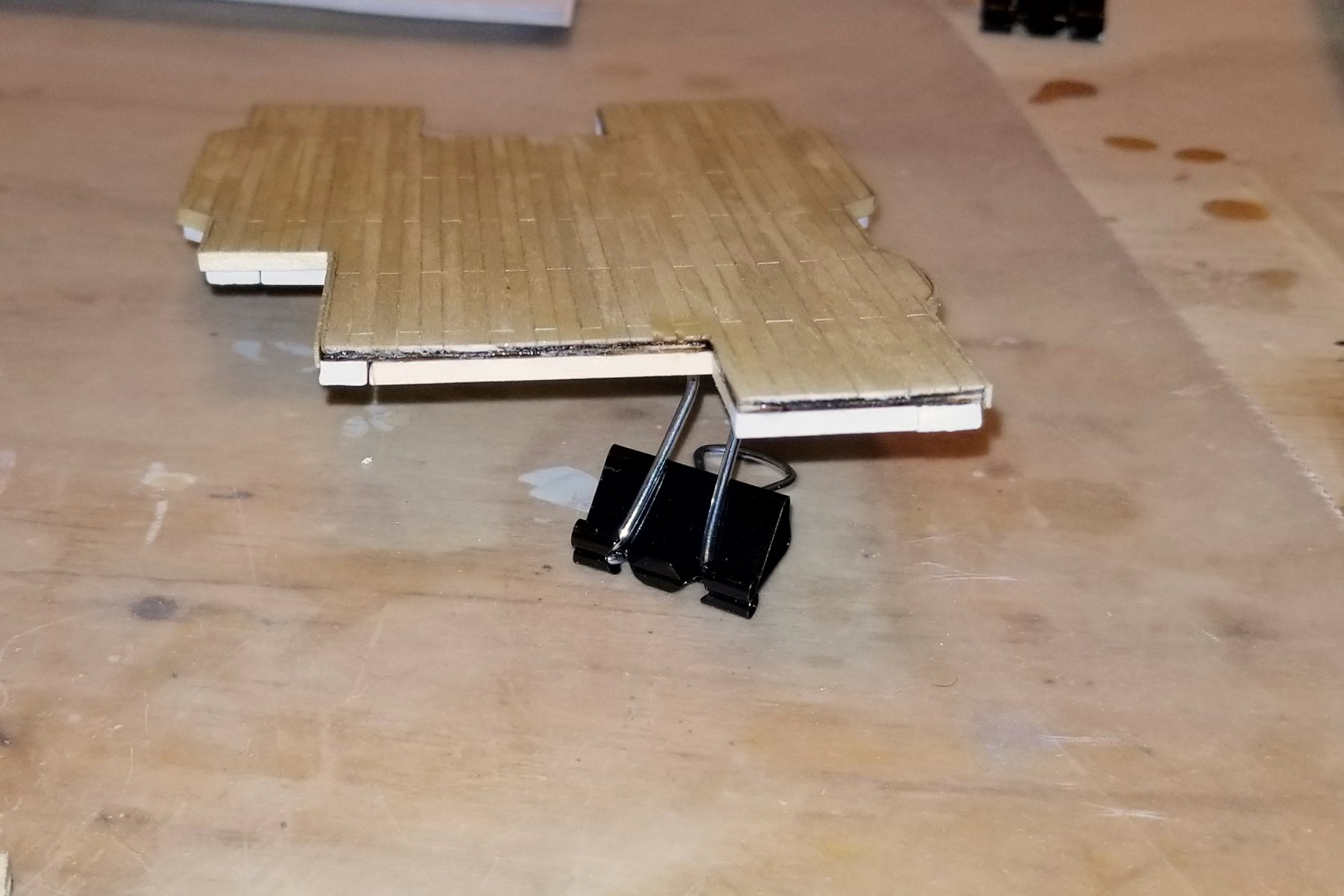
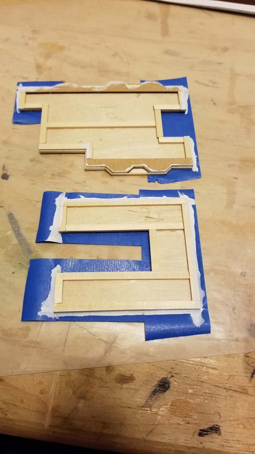
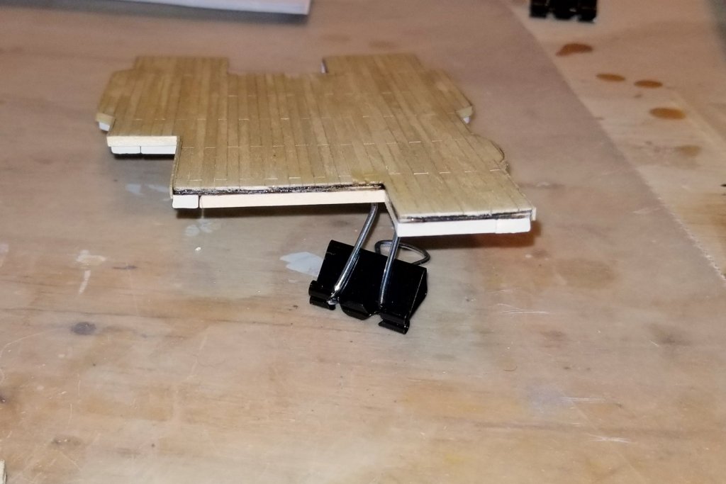
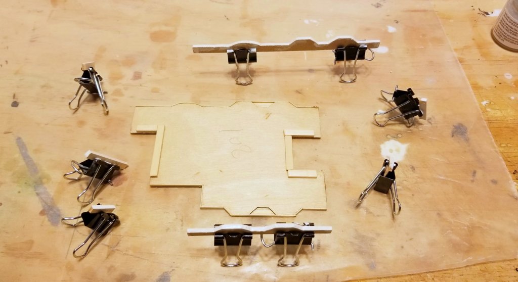
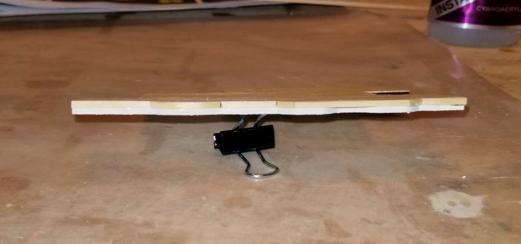
[NOTE: for some reason the pics below were saved in reverse order. Just a note because I reference them below in the order I uploaded them -- but they are shown in reverse order] One of the issues with this kit is the way the instructions are laid out, and how things are sequenced in them. There is basically a section of the instructions that references the picture book, and then another section that references the plan sheets -- and they overlap! So it's necessary to be careful to look ahead in two instruction sections plus the relevant plan sheets and the picture book, to avoid making a mistake in the step at hand. Case in point is the small deck shown here, which I planked a few days ago (picture in an earlier post). Now the instructions have me adding a very thin cabin structure, and what wasn't clear to me is what color it needed to be on the sides. If I just went by the instructions, I'd glue the bare wood, and then discover later on how to paint and decorate it -- or whether it should be painted at all. The pictures in both books (there is one that shows deck fittings, but not ALL of the decks) don't show it clearly, and if you had to guess from those you'd say that maybe you leave it bare wood. But of course that couldn't be the way the real ship was built. So after searching several times through the instructions and plans I found a section much further on that talks about mounting this cabin structure on the deck and painting it white. The instructions actually read in that sequence, but you'd figure that a modeler would paint first. The tricky thing is that the cabin is so thin that it would be really hard to keep paint off the side of the deck, or you'd have to mask. So once I figured that out, I decided to paint first and then glue on, which still requires careful cutting of the wood pieces and fitting them (using clips to hold in place) before painting and then gluing. The pics below show the loose pieces cut and painted, drying, then a side shot of the cabin structure, and then what the cabin structure will look like on the main deck (although there are PE decorations to go on it). Good result, but a note that this kit requires more cross-referencing and reading ahead than other kits I've built. Regards, David

-
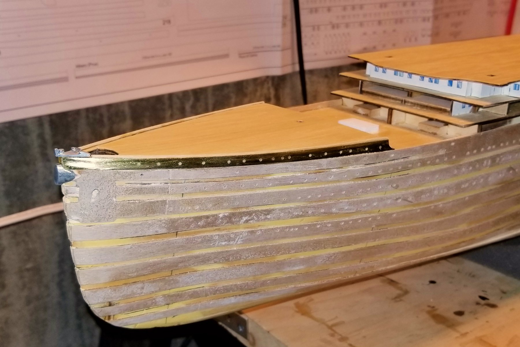
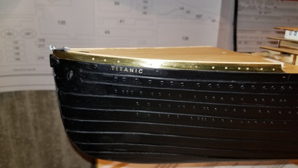
Bow bulkheads and fittings installed. The PE brass will ultimately be painted white. Regards, David

-
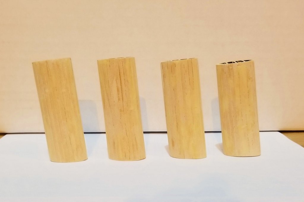
All 4 funnels built. They will be painted later on. The lines you see are showing through wood filler, so they should disappear with paint. Regards, David
-
Thanks, David. I'm finding it really different. One of the things I notice all the time is the scale. My previous build, HMS Fly, was 1:64. This one is 1:250, so I'm constantly noticing the smaller scale as I build. Regards, David
-
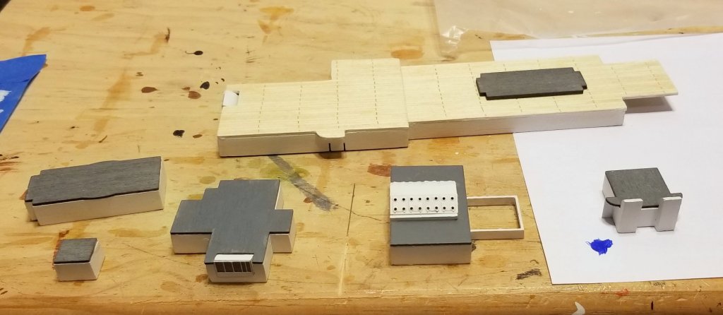
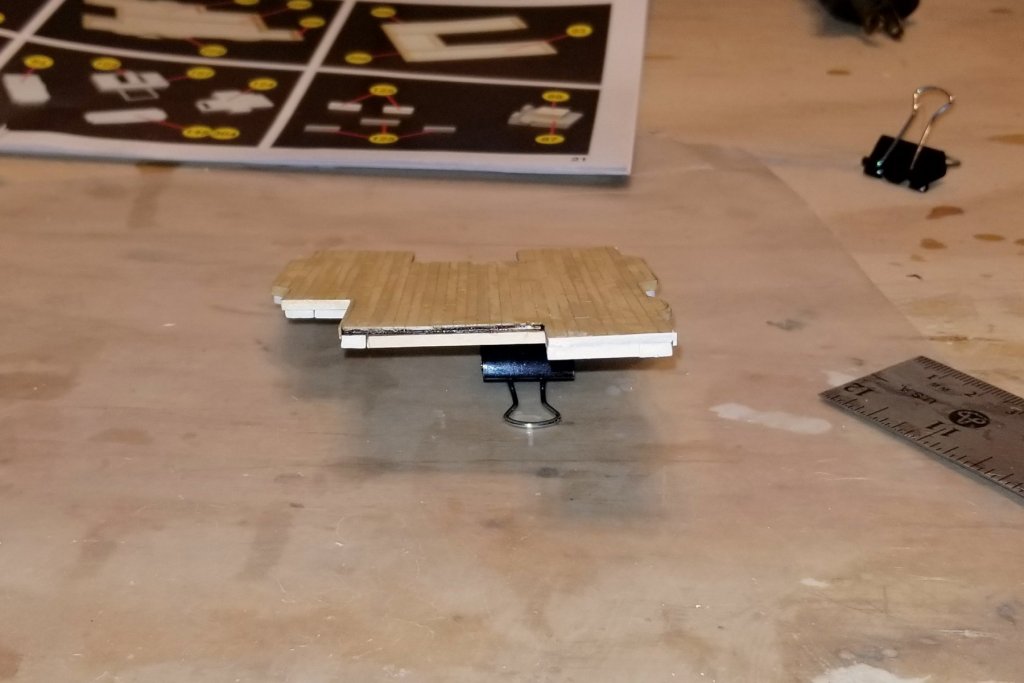
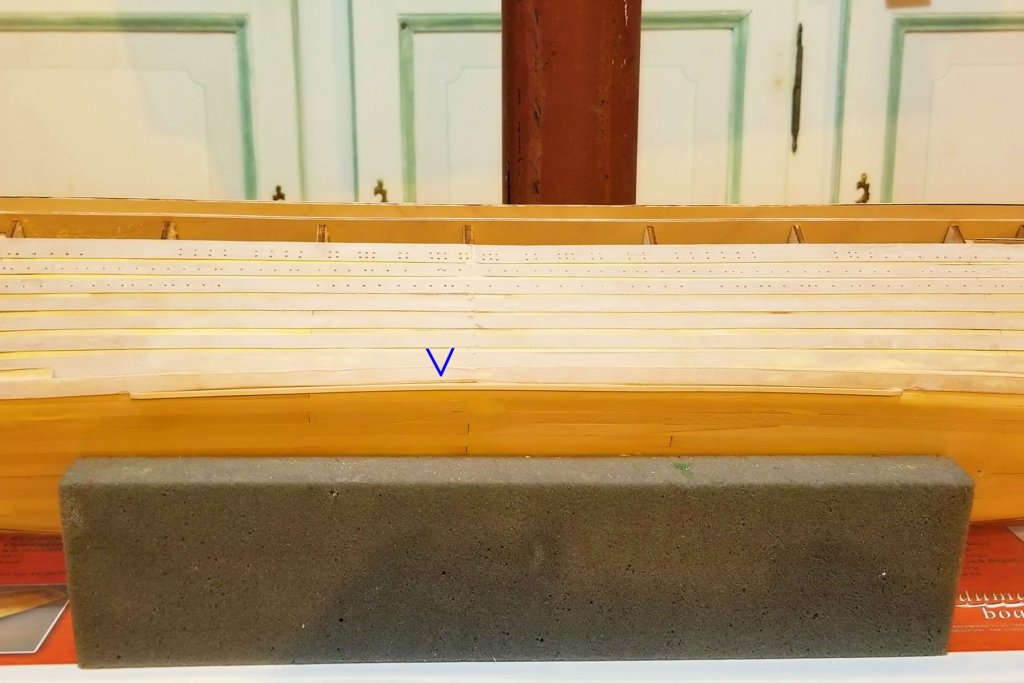
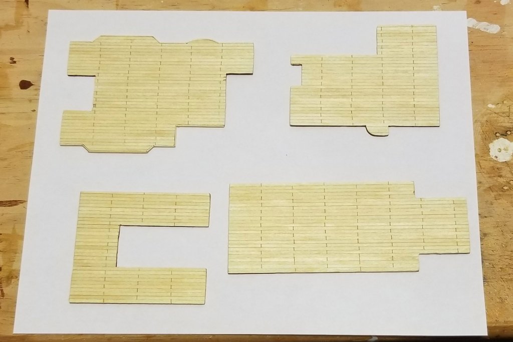
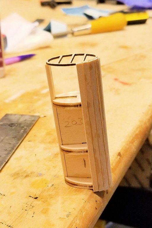
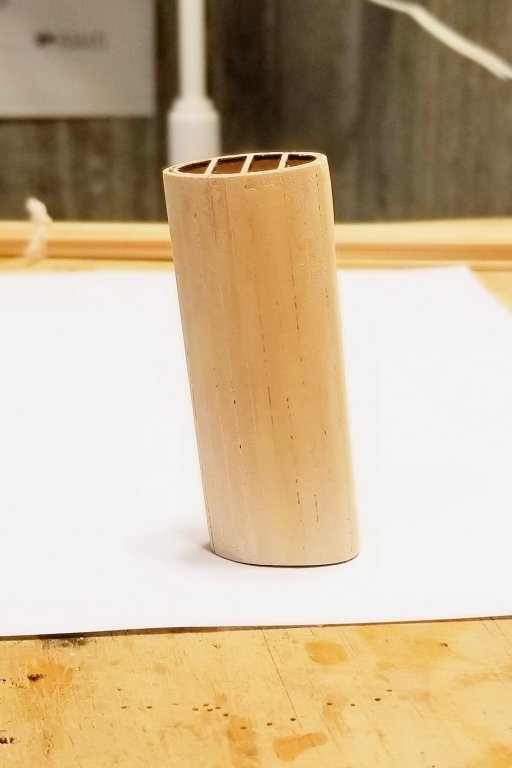
Some progress on different items: Picture 1 is the bilge keels -- below the blue arrow. Picture 2 is 4 small decks that will be on top of the large one. Picture 3 is the stack subassembly, partially completed showing how the planking works for the side. Picture 4 is a completed stack, ready for varnish and ultimately painting. Regards, David
-
Kevin: That's right. On the large deck section I show above, pretty much just the two bands on either side, and there is "stuff" that shows up on those. Regards, David
-
Chris: It's approaching, but I think there is about 1-2 weeks' work left before I get to that point. Regards, David
-
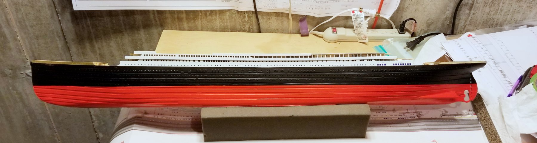
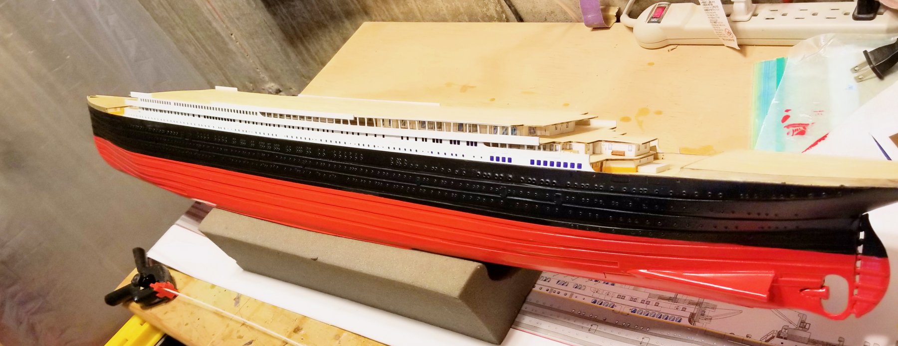
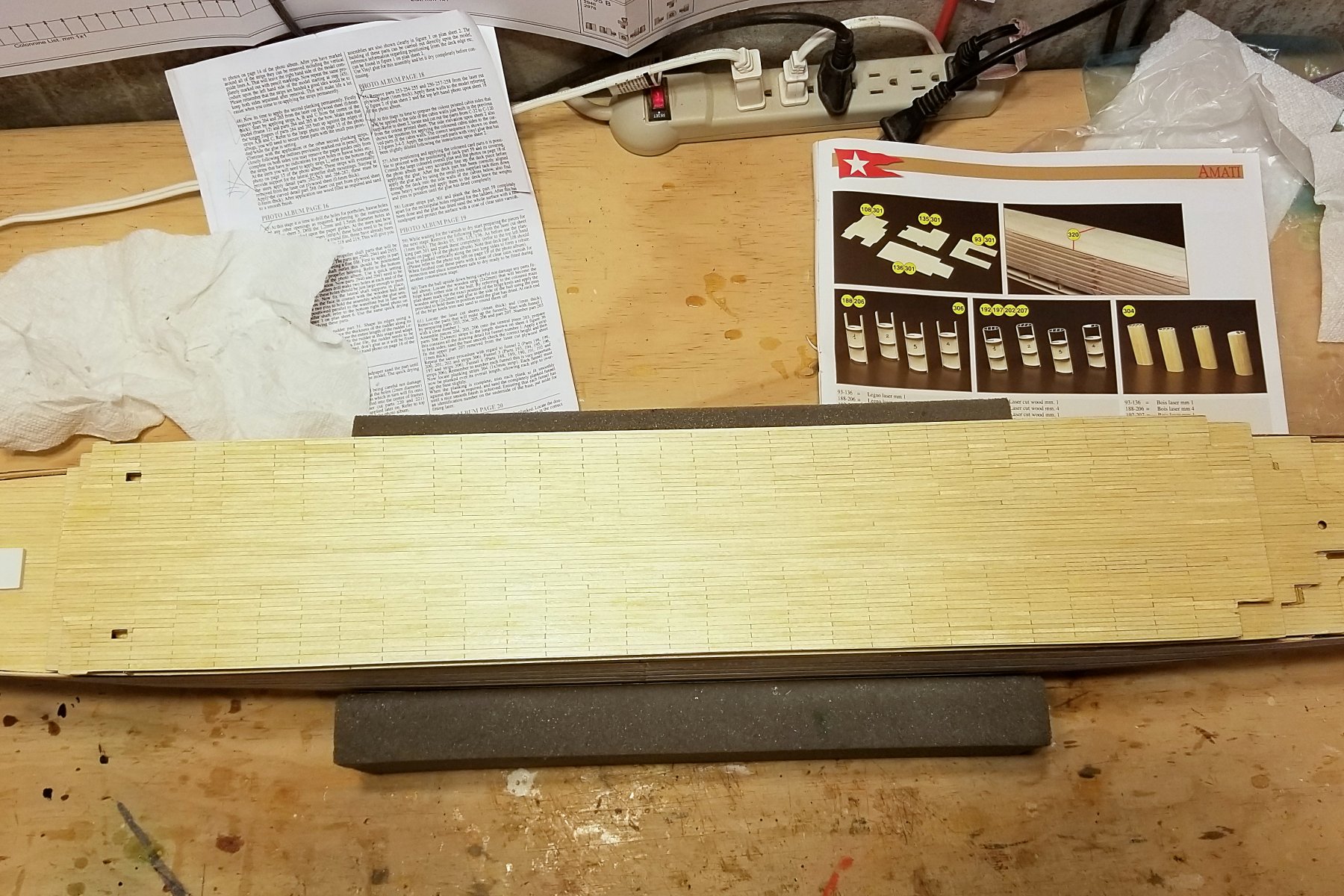
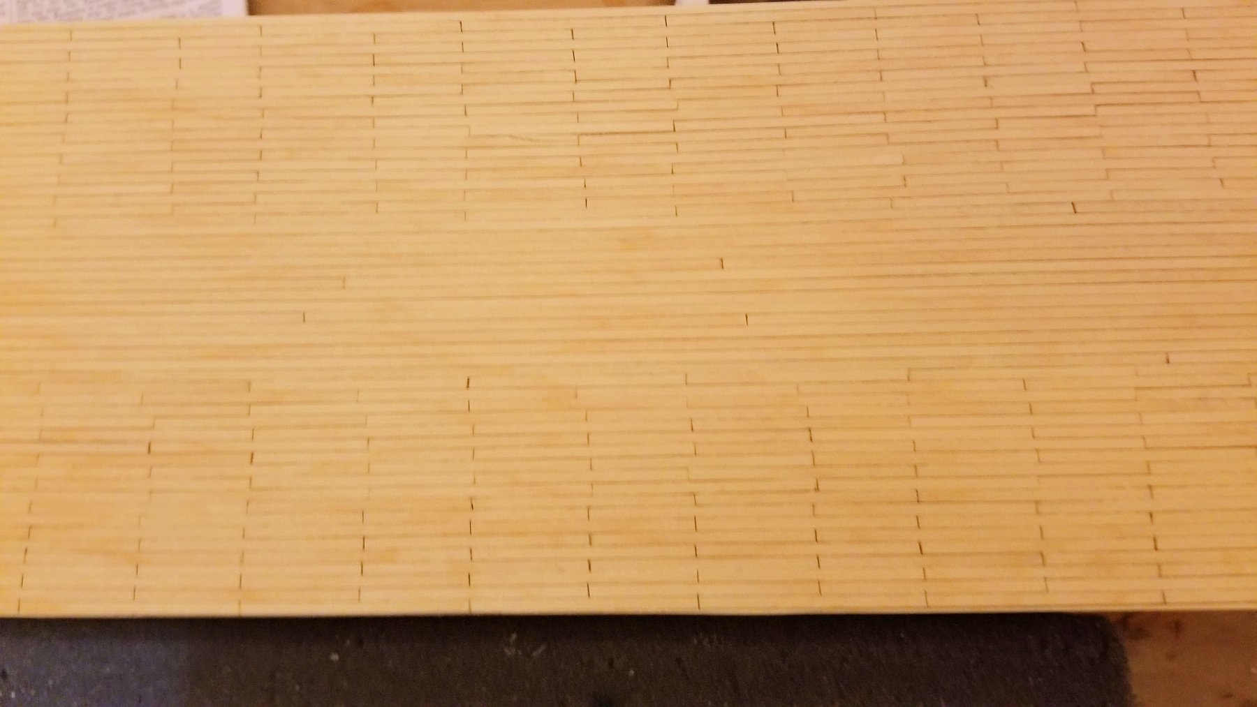
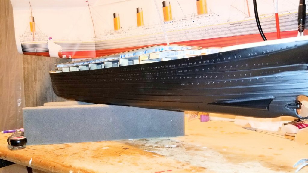
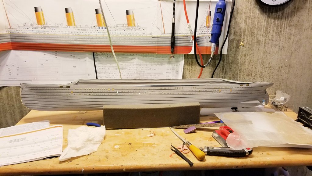
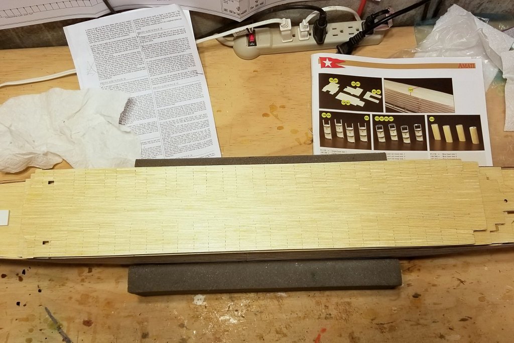
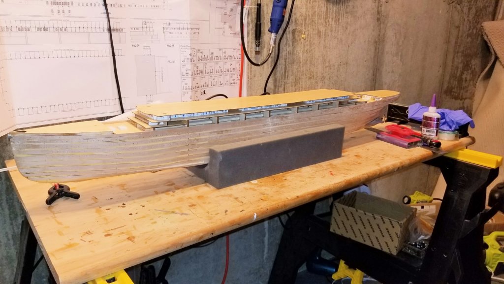
I've added the top deck now on top of the cabins. A couple of notes. Inexplicably, the instructions say to mount the deck on the ship before planking, which would just make everything harder in terms of trimming at the edges and for the ladder holes. This is the first large deck that will actually be visible, so while I just used full-length planks on the earlier ones, on this one I decided to add some staggered planking. But the center of the deck is covered, so I measured that (Picture 1) and then used full length in the center, moving to 40mm staggered on the outer edges. (Pics 2 & 3). The uneven parts near the center actually won't show because I erred on the conservative side for the center area -- it took me some time to figure out how best to do this. I started with 40mm pre-cut pieces, which didn't work very well. I then changed to gluing on full length planks and scoring them against measured lines, which worked better. Pic 4 is the full model so far. Regards, David

- 168 replies
-
- 10
-