HOLIDAY DONATION DRIVE - SUPPORT MSW - DO YOUR PART TO KEEP THIS GREAT FORUM GOING!
×


Tomculb
-
Posts
341 -
Joined
-
Last visited
Content Type
Profiles
Forums
Gallery
Events
Everything posted by Tomculb
-
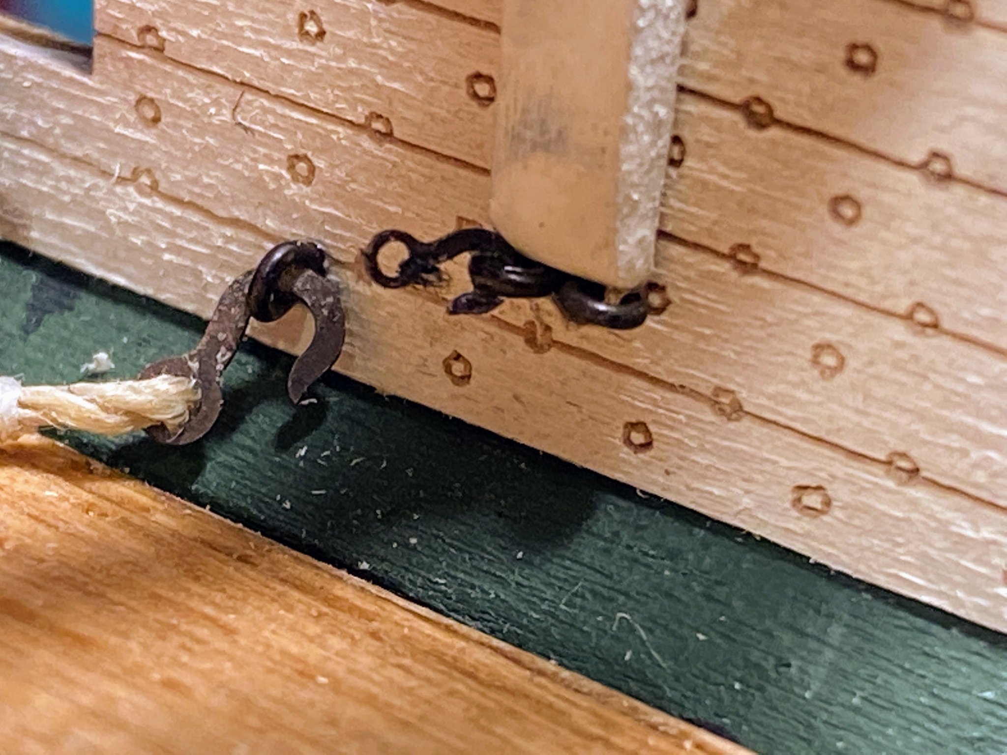
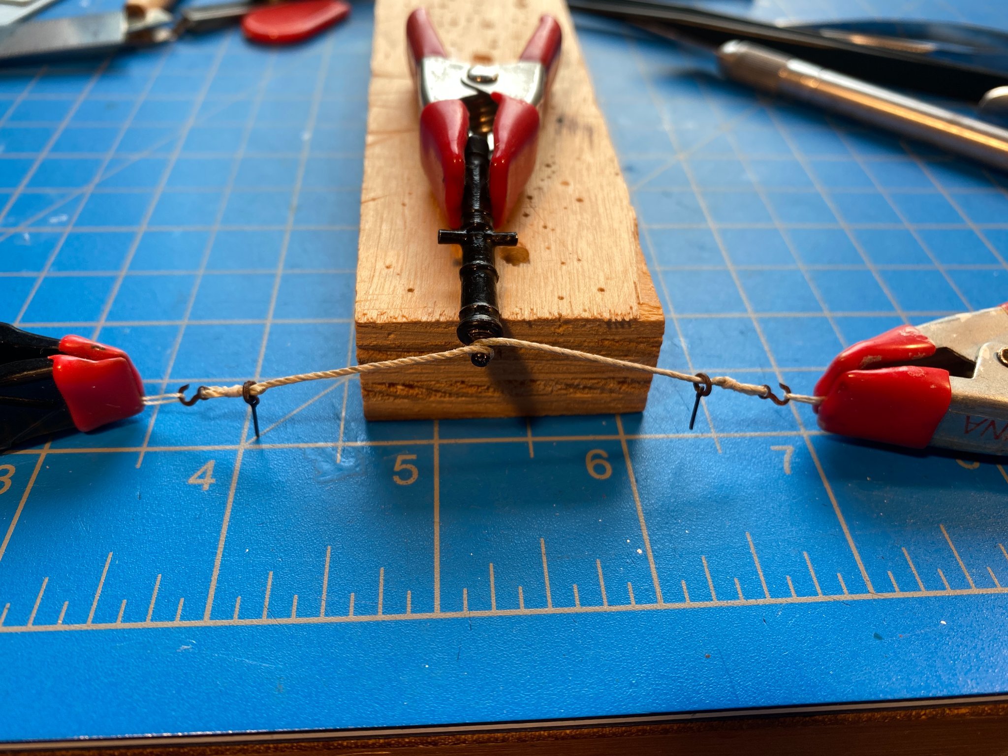
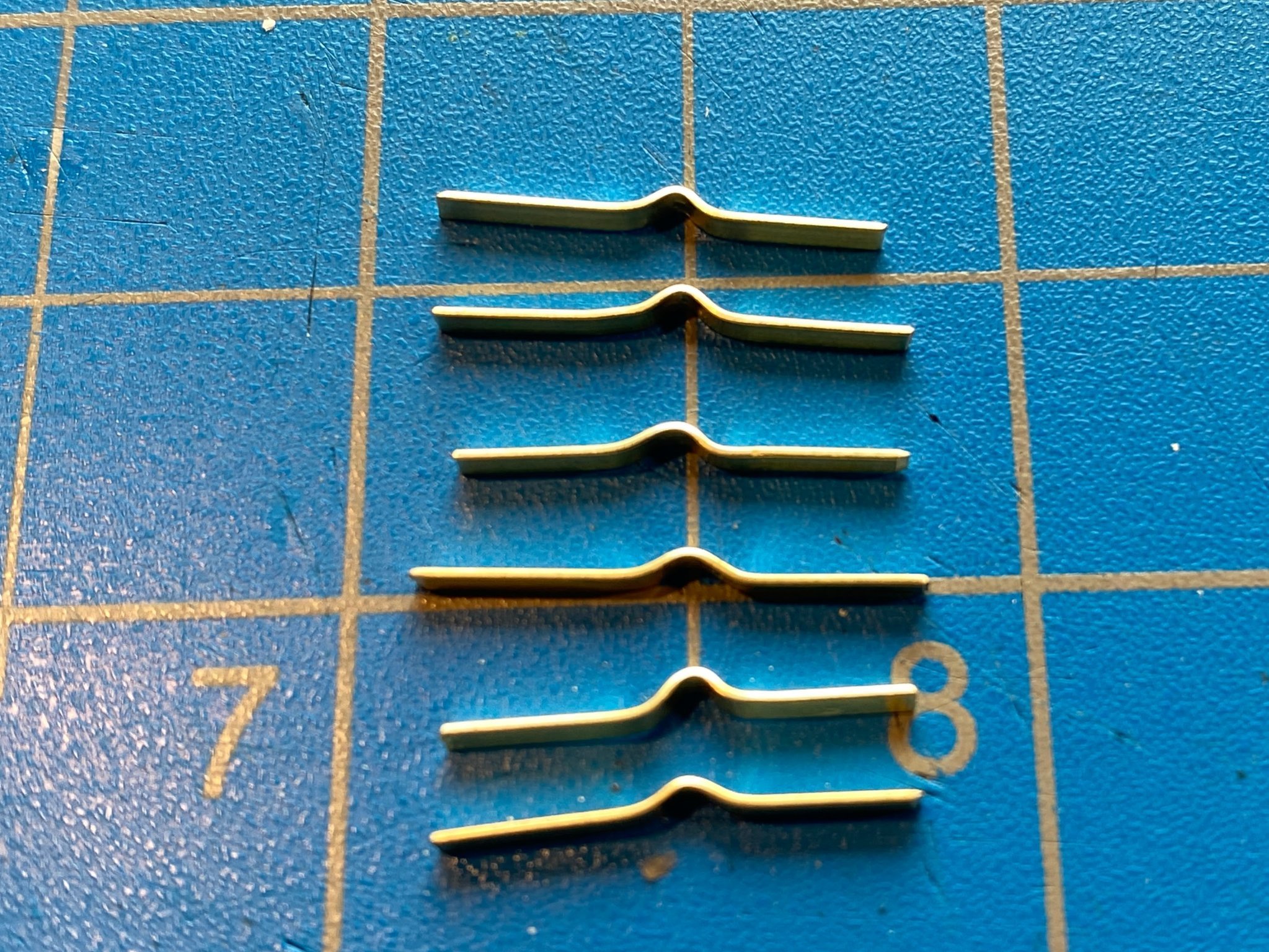
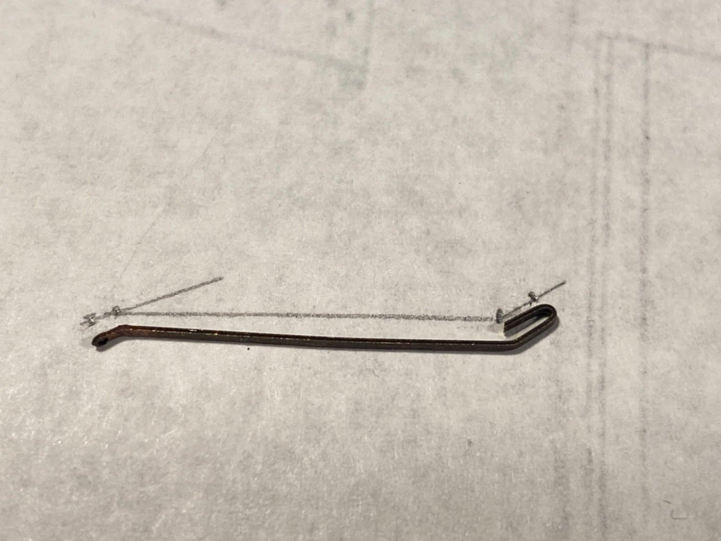
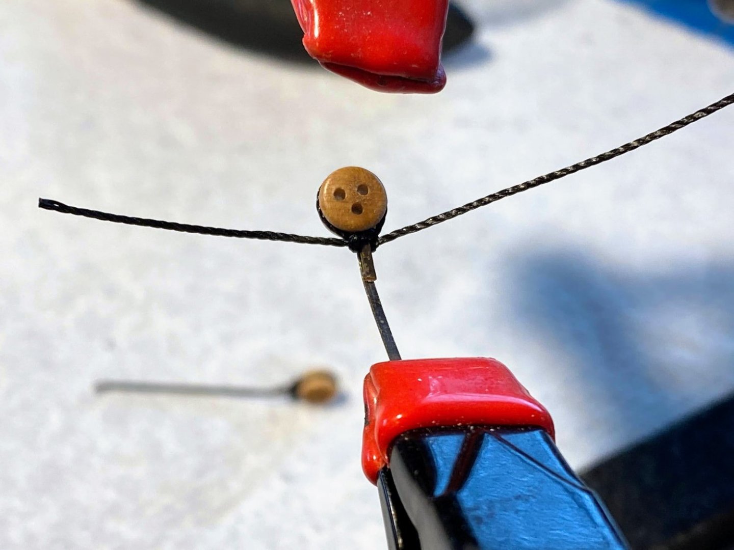
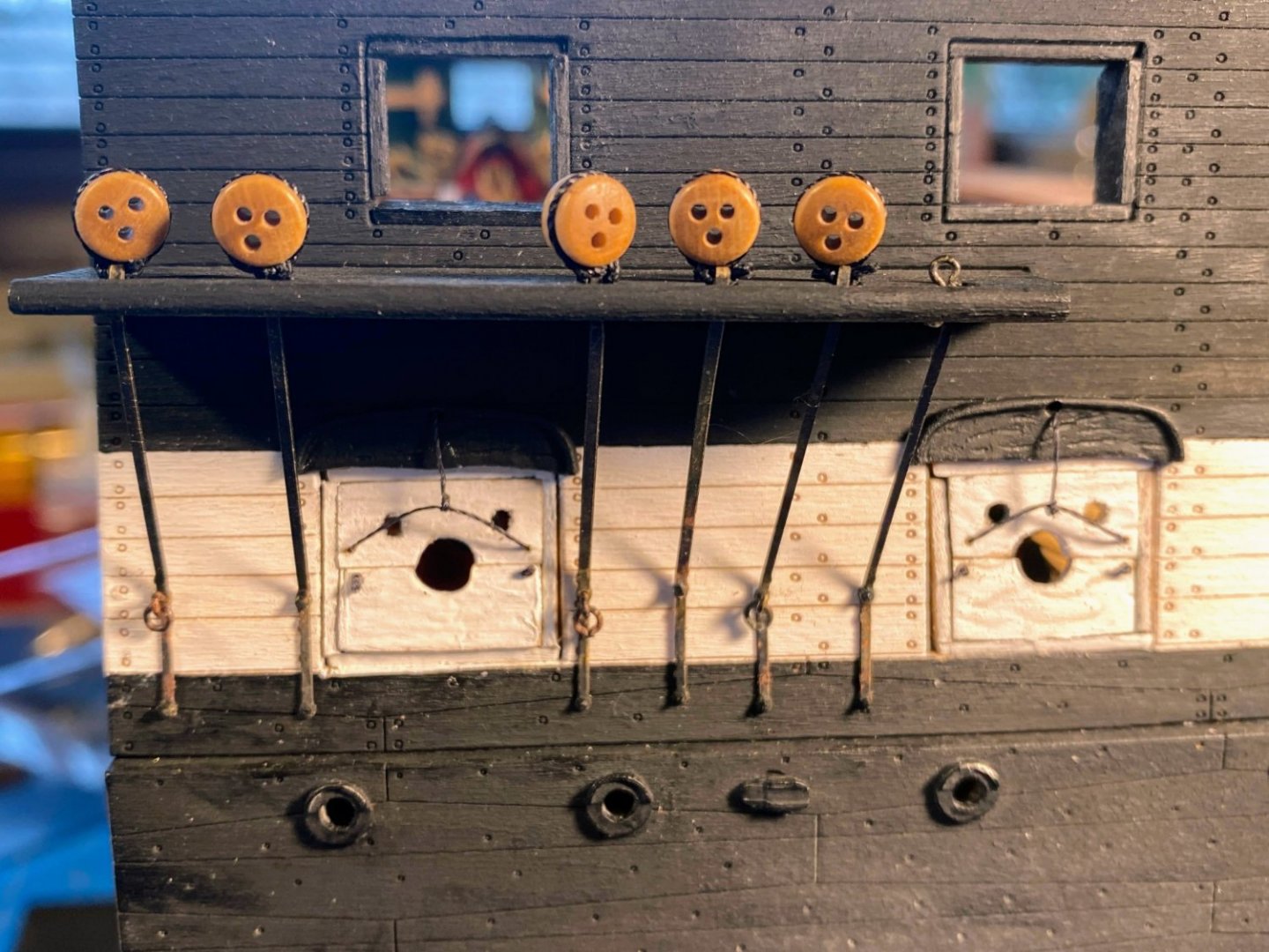
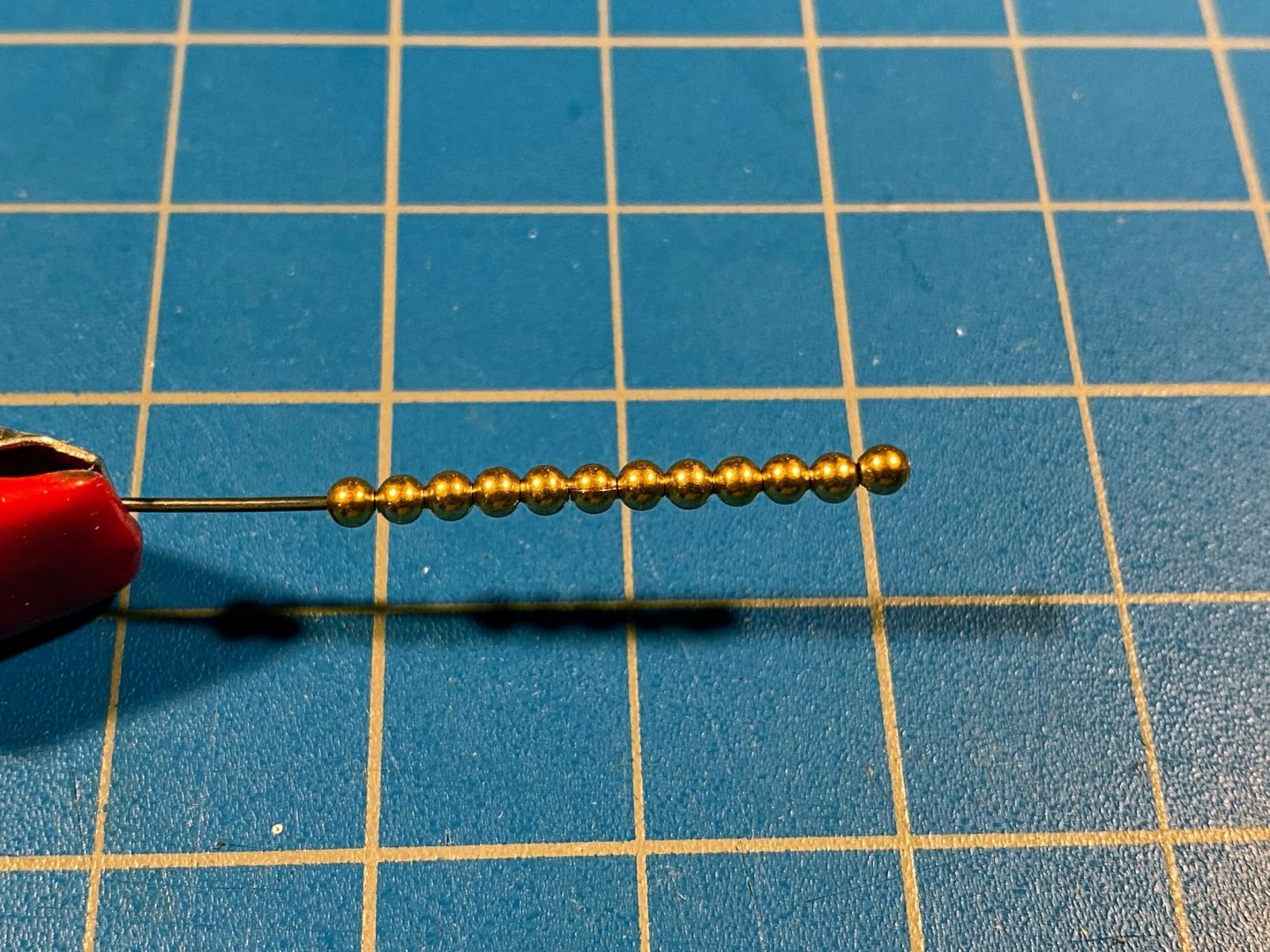
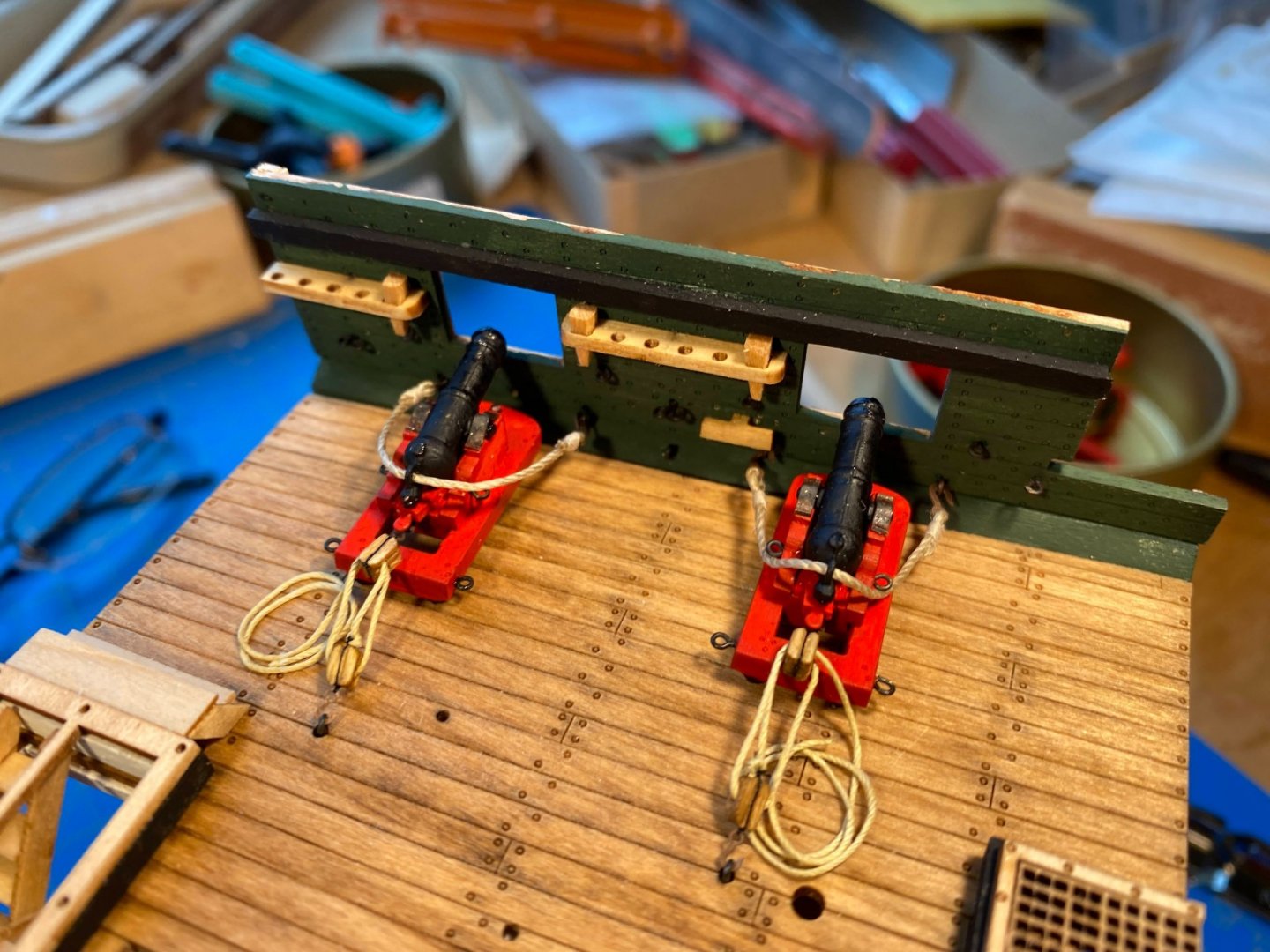
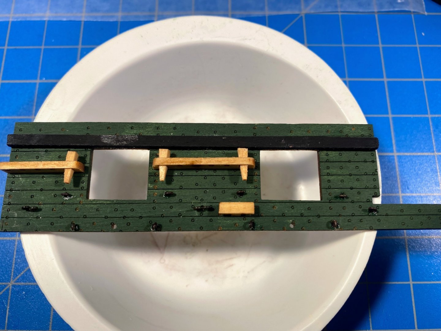
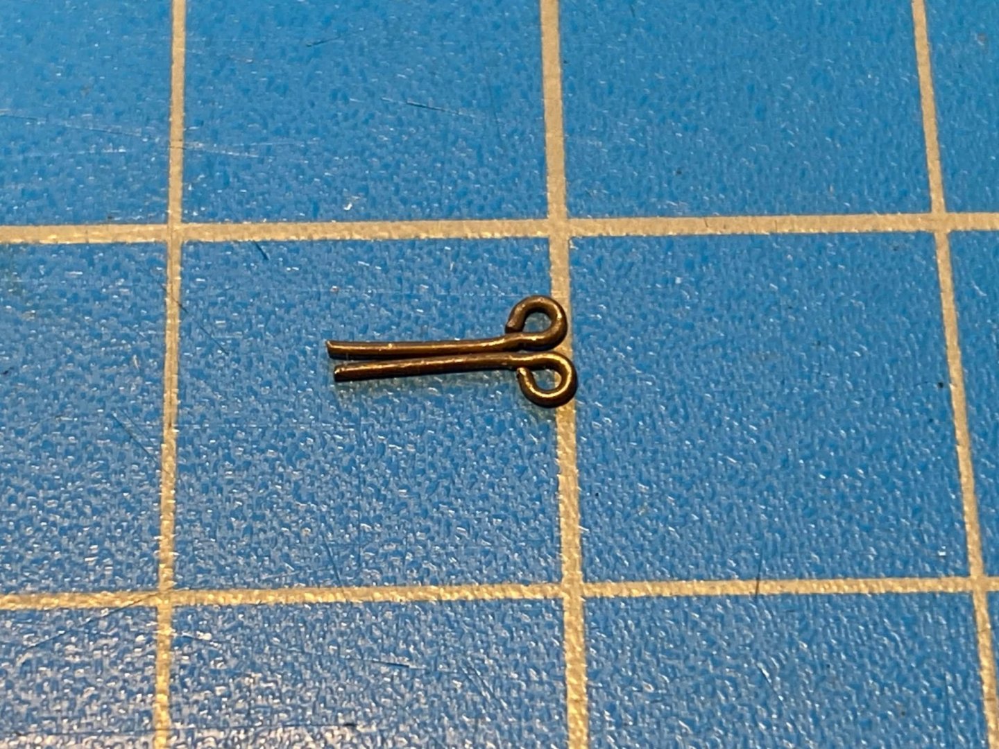
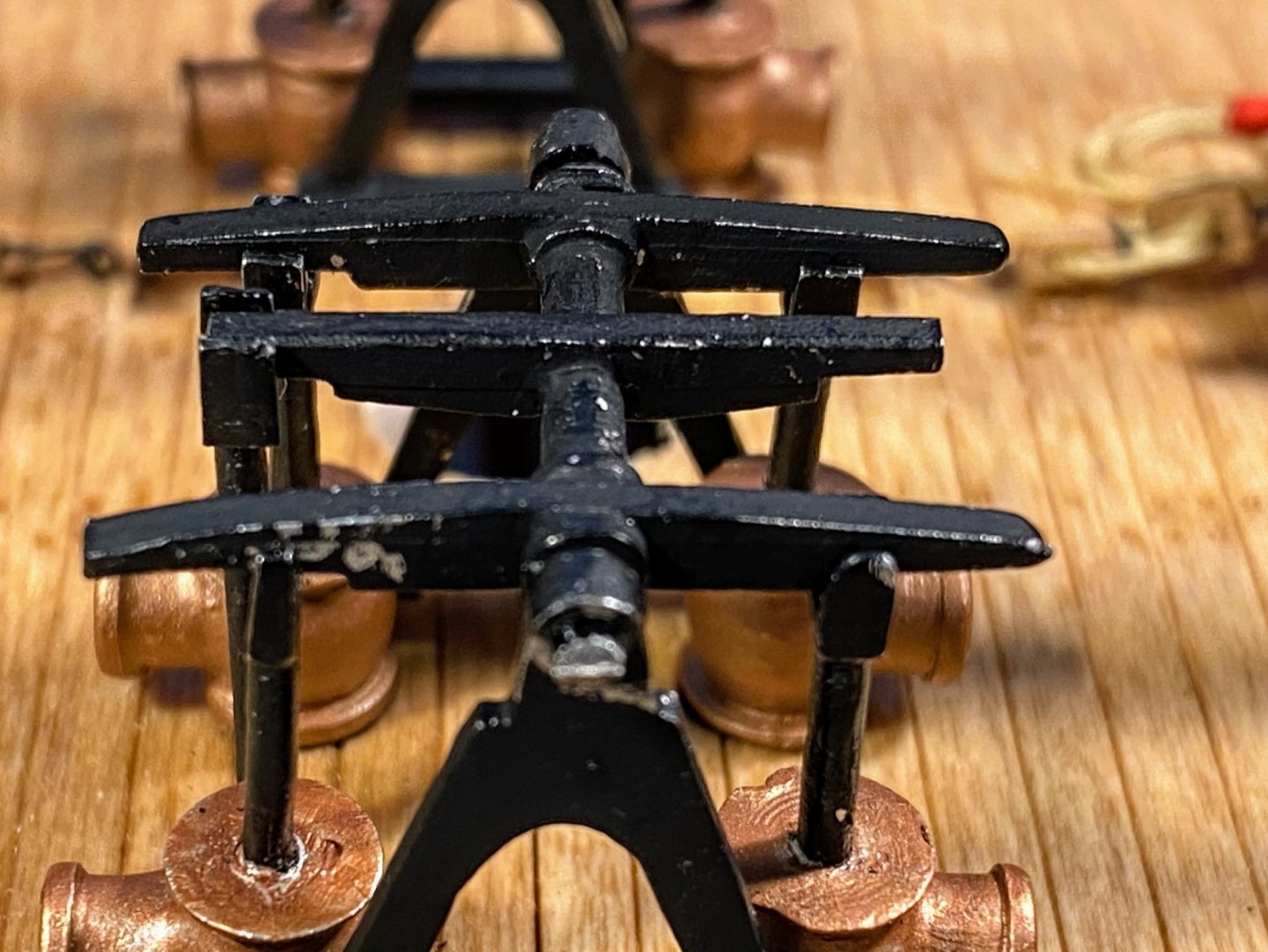
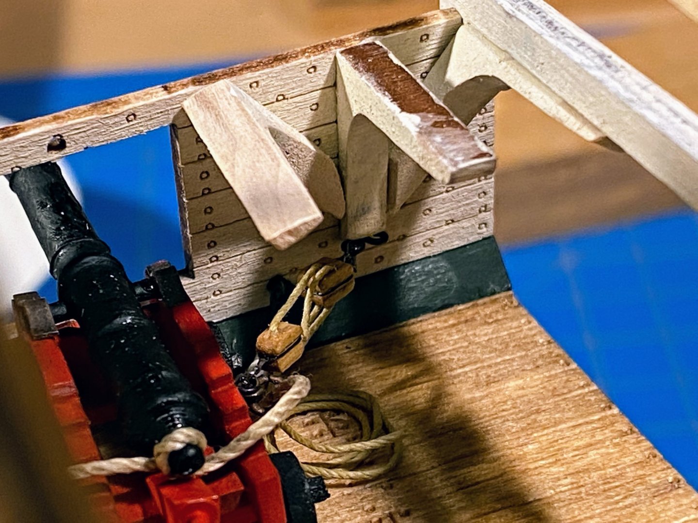
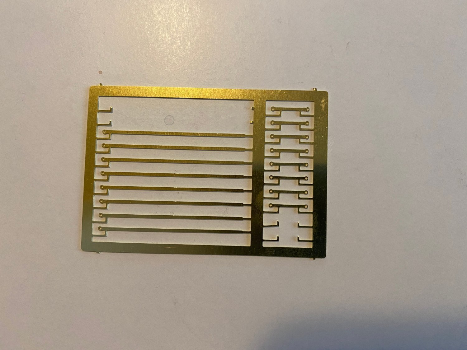
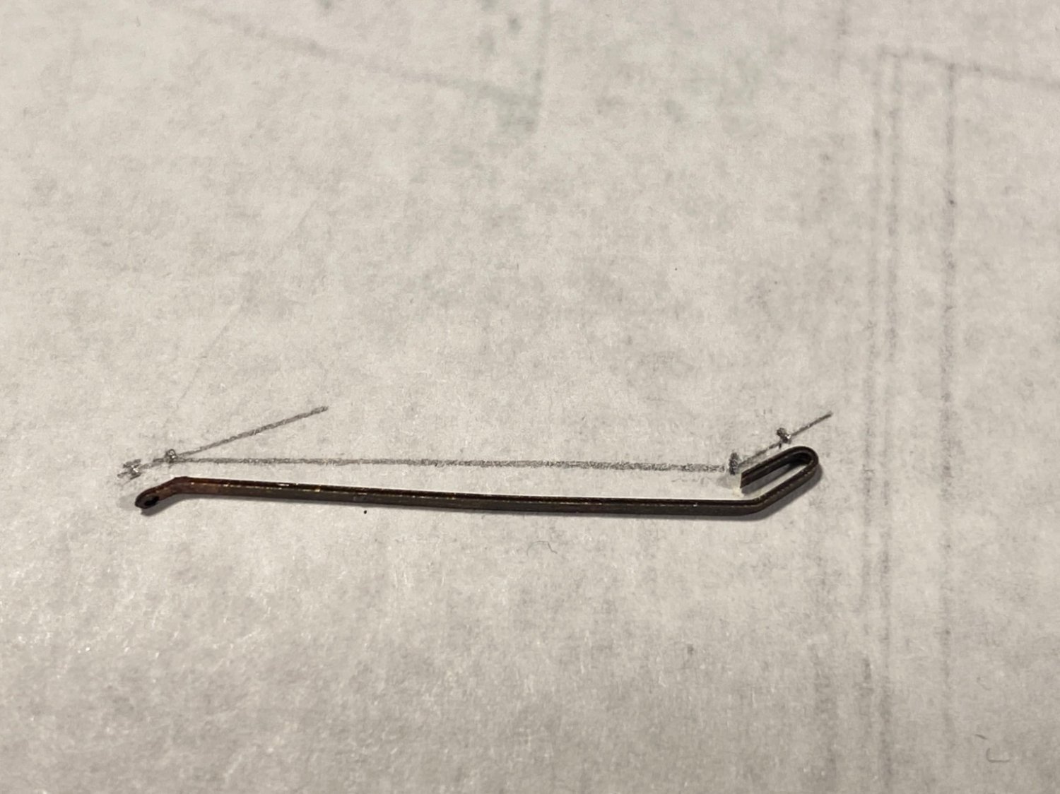
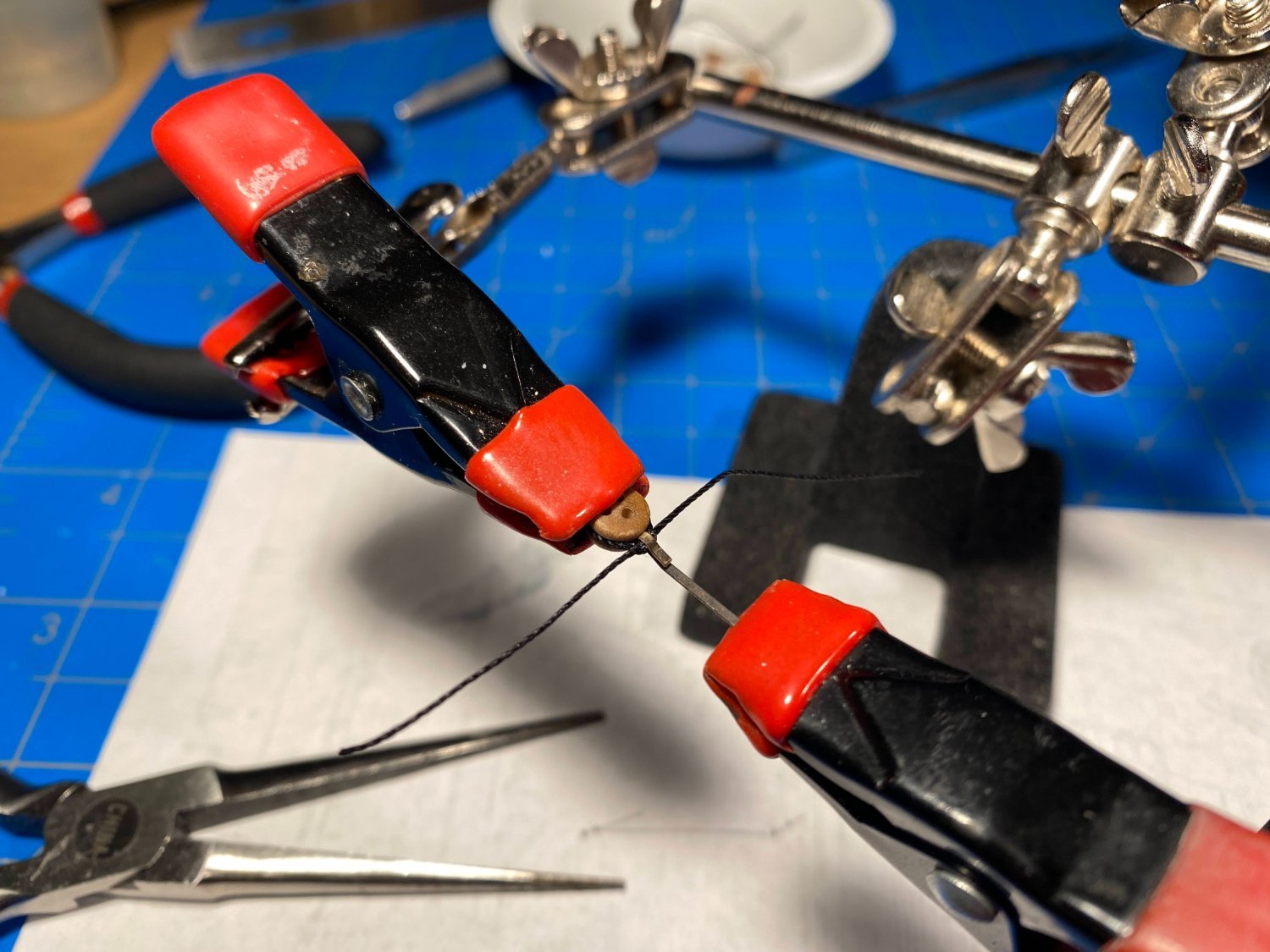
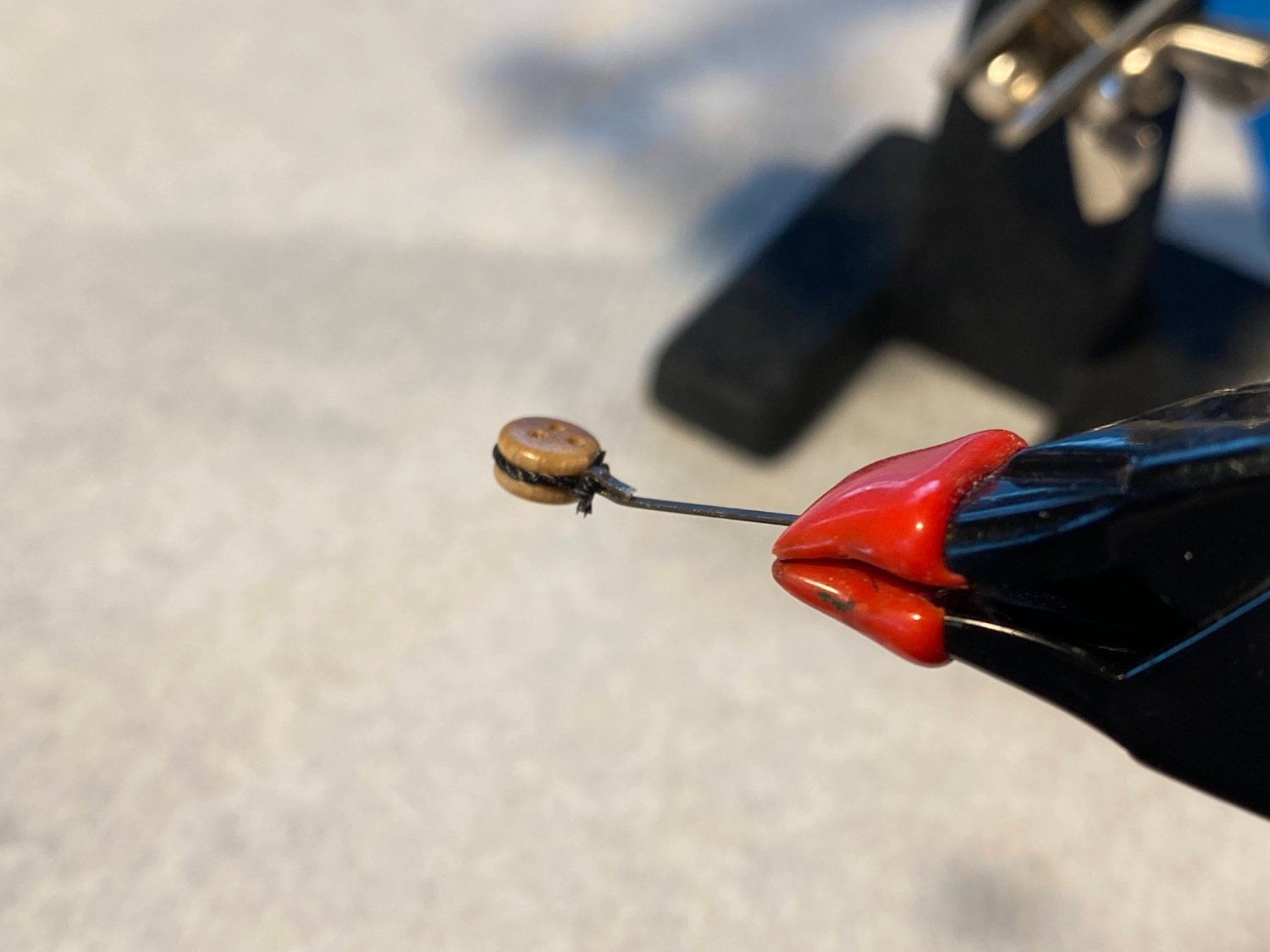
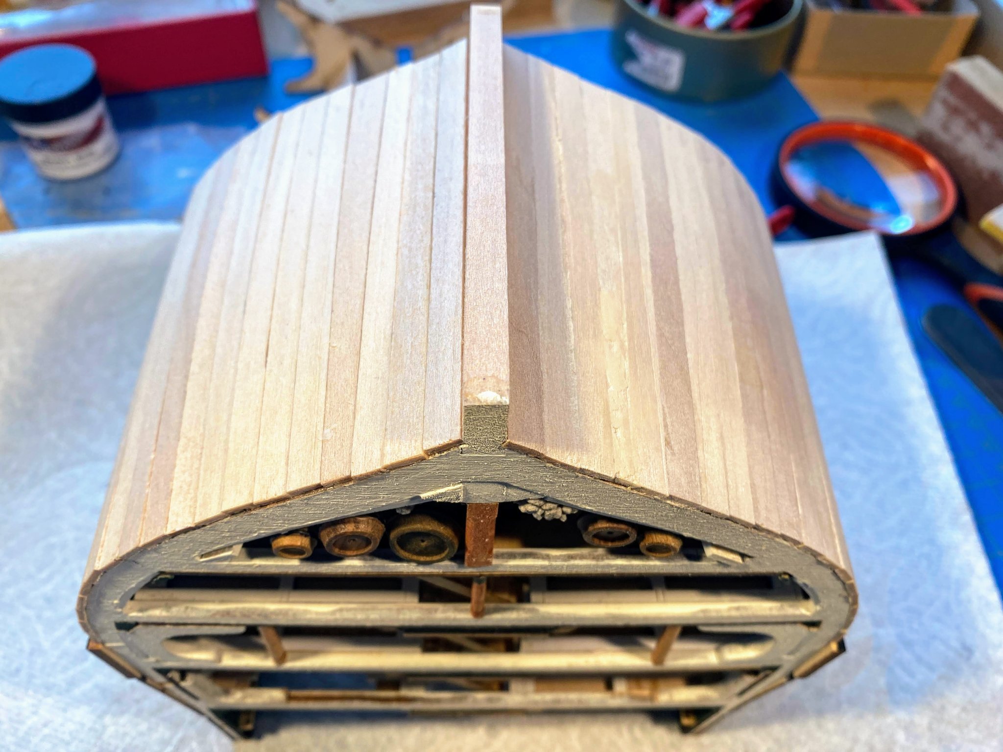
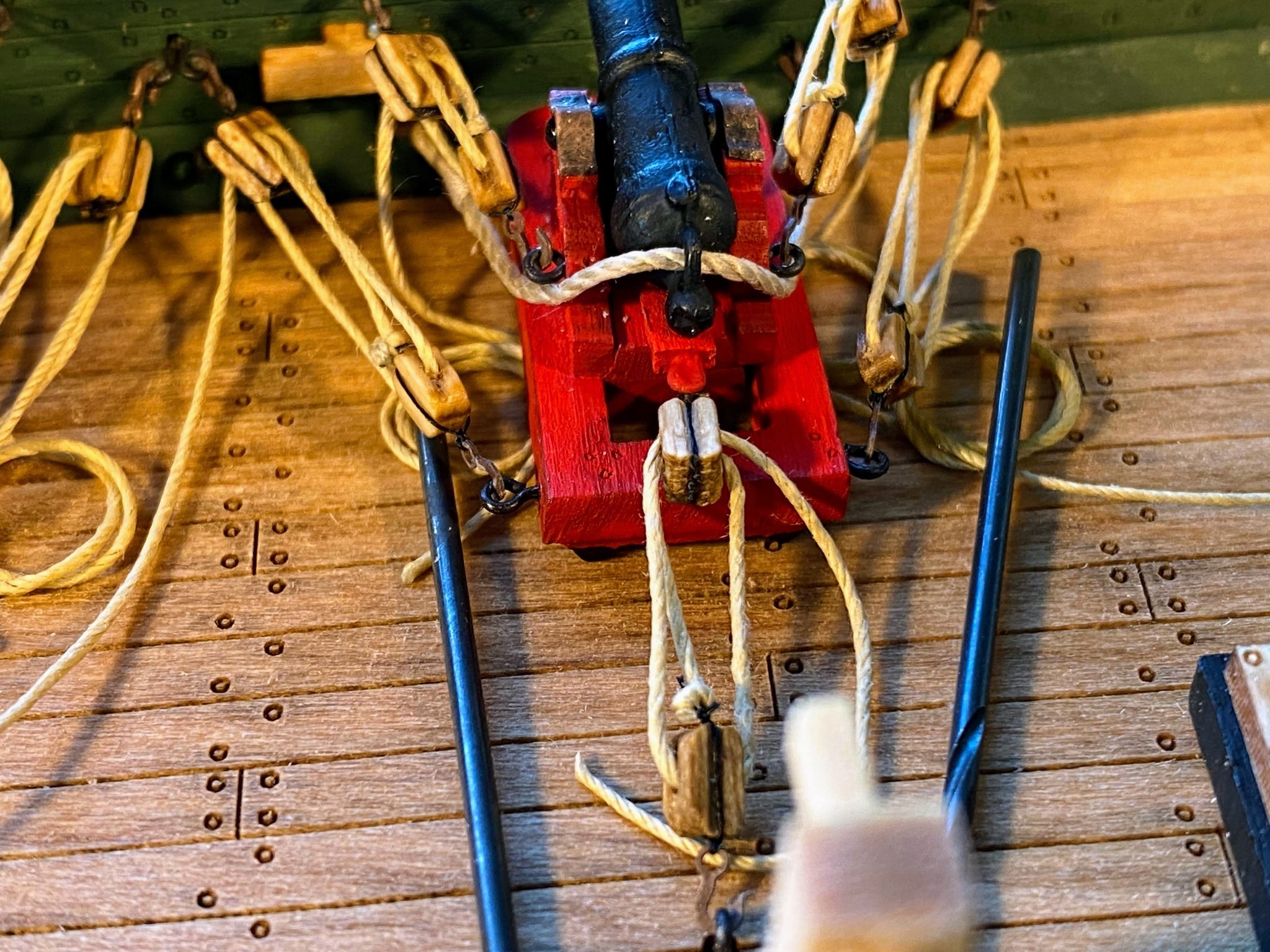
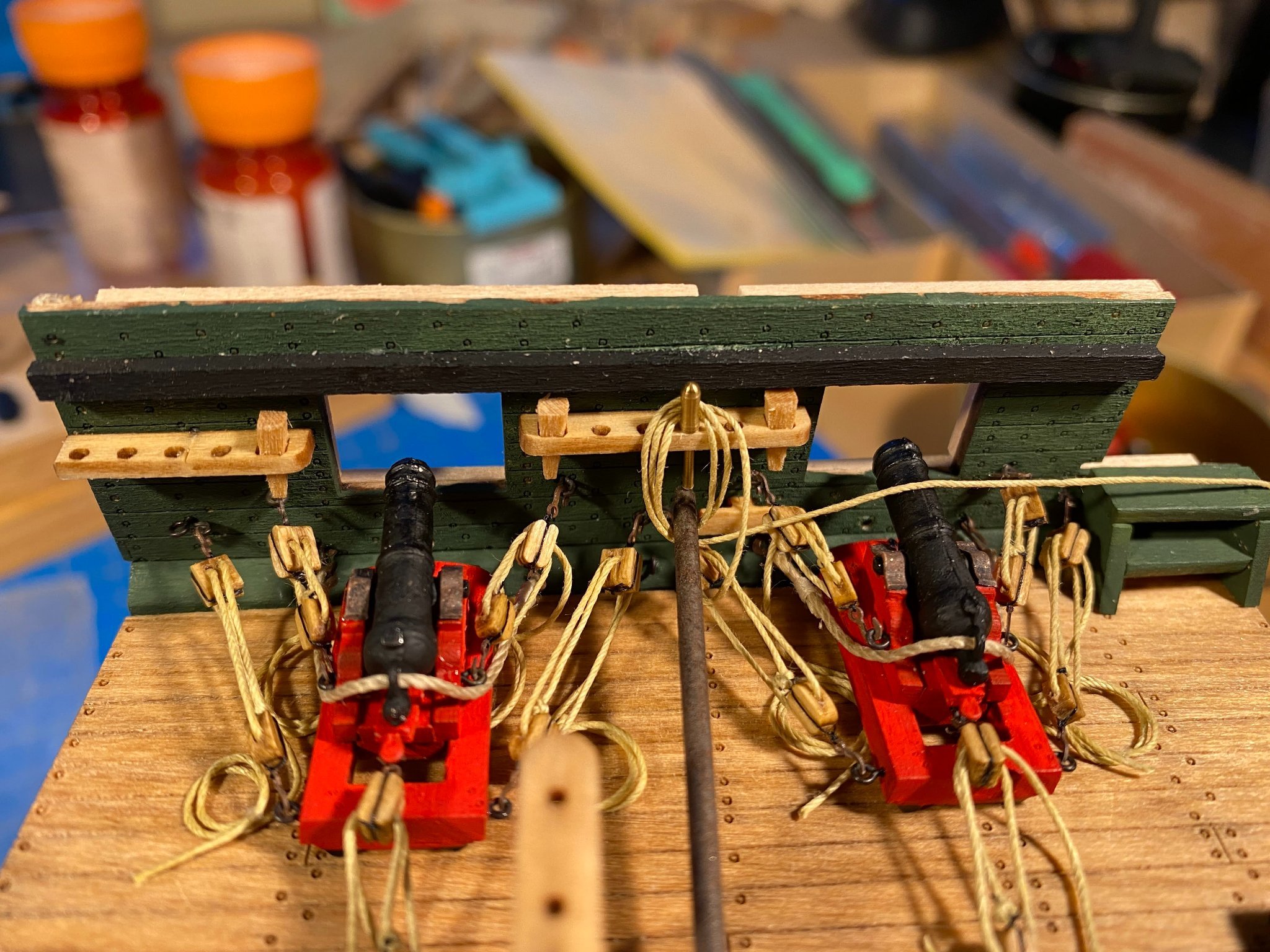
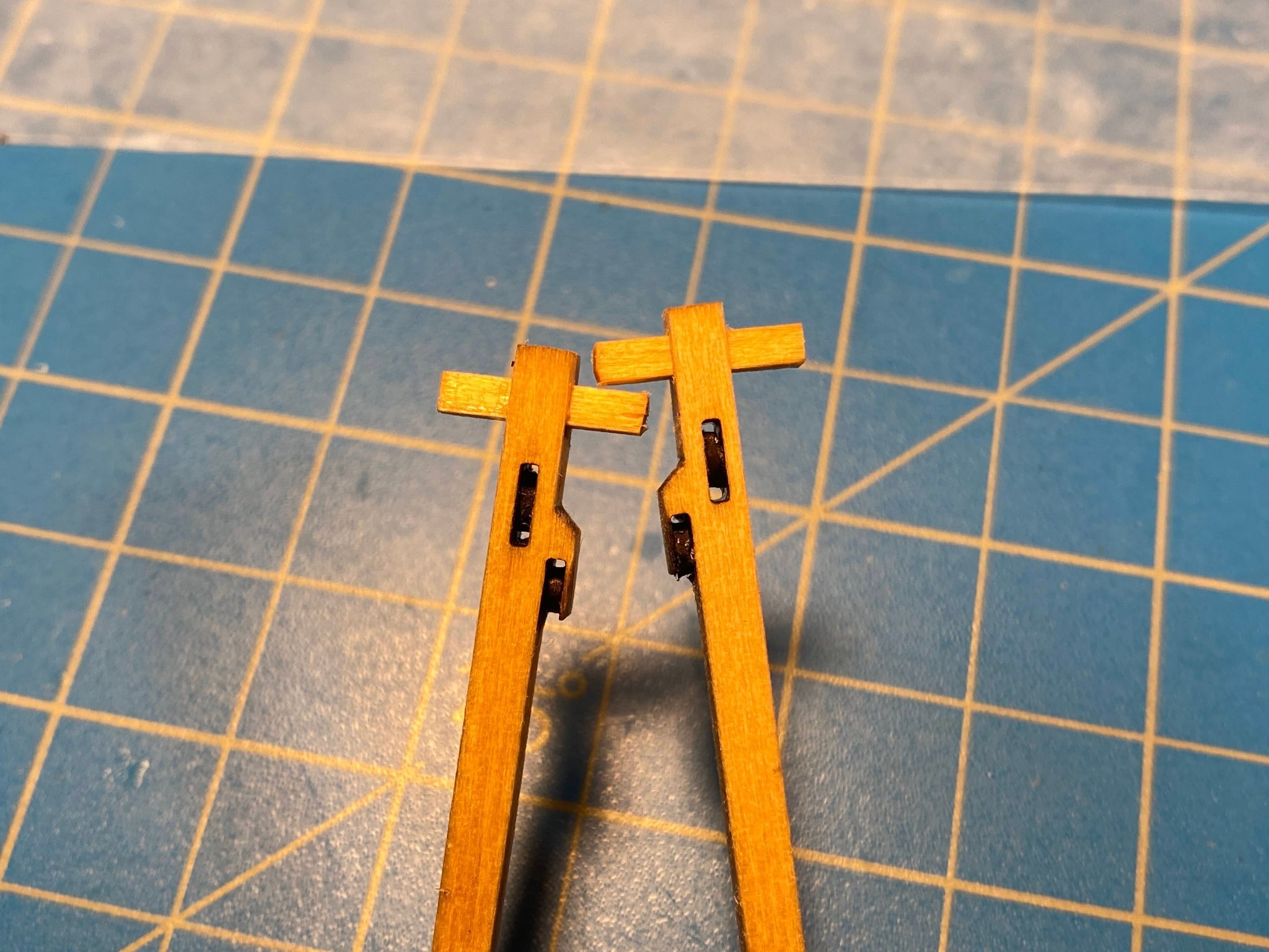
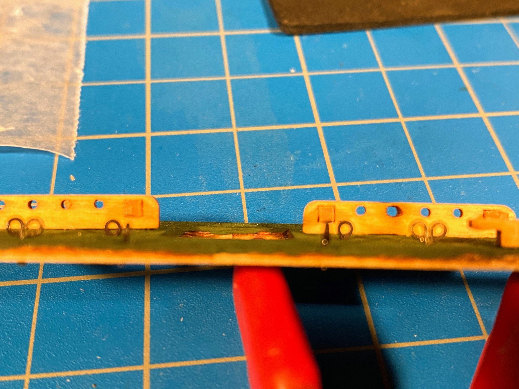
 The channels are laser cut from a 3/32” sheet. There are six chain plates on each side (5 attached to deadeyes; 1 attached to a small ring), and it appears that MS is having some difficulty in their counting department. The channels have only 5 notches for chain plates (a fault easily remedied by cutting another notch), and the supplied photo-etched sheet of chain plates contains only 10 of them. Fortunately MS has a reputation for great service when parts are missing or broken (a well deserved reputation in my experience), and they sent me a second sheet of chain plates, so now I have extras. The plans show the channels tapering toward the outer edges, as one would expect as the ship’s designers would probably want to reduce weight on anything extending beyond the walls of the hull. I tapered them from 3/32” to 1/16”, glued a 1/16” square strip along the outer edge, and sanded it round. The instructions suggest a more elaborate molding along the outer edge using the molding shaper discussed in my previous post, but with only 1/16” to work with, and painted black no less, I decided that would not be worth the effort. The instructions suggest using wire to strop the deadeyes to the top of the chainplates, but I have always found rigging thread easier to work with than wire. Getting the chain plates bent just right took some trial and error, differences of fraction of a millimeter being quite apparent when installed on the hull, so once I got it right on the first one, I reproduced it on paper and tried to bend all the others accordingly. As the instructions mention, they are also a little to long and need to be cut shorter. Then I simply took .021” black thread, wrapped it around the deadeye, tied half of a square knot tightly, loosely tied a second half of the knot, slipped the bent hook of the chain plate between the two halves, tightened everything up, bent the hook tightly against the knot, and added a large drop of diluted white glue for additional security. The deadeye that emerged once everything dried looked so happy I almost hesitated to cut his arm’s off. 🤪 The instructions show the deadeyes left natural, but the real ship has them painted black, and before I got to this stage, I gave a fair amount of thought as to how I wanted to do mine. But when it came time to tie the first one to the chain plate, I was so focused on that project that I didn’t even think about painting it. Apparently my subconscious brain made the decision for me. As can be seen above, the chain plates actually come in two pieces, a longer one running from the channel down to the hull (referred to as the “strap” in the instructions) and a shorter one attached to the bottom of the strap, running down flush with the hull (referred to as the “link”). Installing them would probably have been a lot easier had they been provided as one long piece. In any event, I dropped the chain plate/dead eye assembly through the notch in the channel, then brought the lower end of the chain plate to the surface of the hull, and drilled a hole, trying to keep each chain plate perpendicular to the waterline and parallel to the adjacent chain plate. I had previously enlarged the holes in the strap and link parts of the chainplates (as I did with the hammock stanchions discussed in my previous post), as they come supplied with holes too tiny to get much of anything through them. On alternate chain plates, the instructions (and the real ship) have an eyebolt with a ring hanging from it where the strap and link meet. I’m not sure what function these rings serve, but I suppose they could be used when a small boat ties up along side or when the ship is tied to a dock. On the alternate chain plates the pictures in the instructions show nothing in the holes where these pieces meet nor at the bottom of any of the links. On the ship obviously the chain plates would be secured in these places with large thorough-the-hull bolts, as this is what holds the masts up, and some sort of pin in each of these places on the model would help help assure the chain plates stay in place when the ratlines are firmly tied on. So I dug through my leftover materials from other builds, found some brass wire the same thickness as the wire eyebolts, and pinned the pieces of the chain plates in place with 1/8" lengths of wire, secured with a drop of medium CA glue. Doing this was quite a bit more difficult than it sounds, as anyone working with tiny pieces of photo-etched brass knows that those pieces generally ignore all the rules of gravity, aerodynamics and Newtonian physics. But while it took some effort (and dexterity which seems harder to come by as the years go by), I eventually finished the starboard side, and the port side is now maybe 75% finished. A tiny drop of flat black paint applied to each pin hid the brass, and created something that might look like a bolt head but at this scale too small to really see. I did make the mistake of looking at a couple of them through a magnifying glass, but I don’t think I’ll do that again. 😃 Fortunately the links in person look darker than they do in the picture below. As mentioned (and can be seen) above, the sixth chain plate on each side is attached to a ring rather than to a deadeye. Here I took a wire eye bolt, bent the stem 90 degrees to the eye, and glued the stem to the underside of the channel with a few dabs of medium CA. The hole in the channel was large enough to accommodate both the stem and the chain plate, and I secured both in place with another dab of CA.
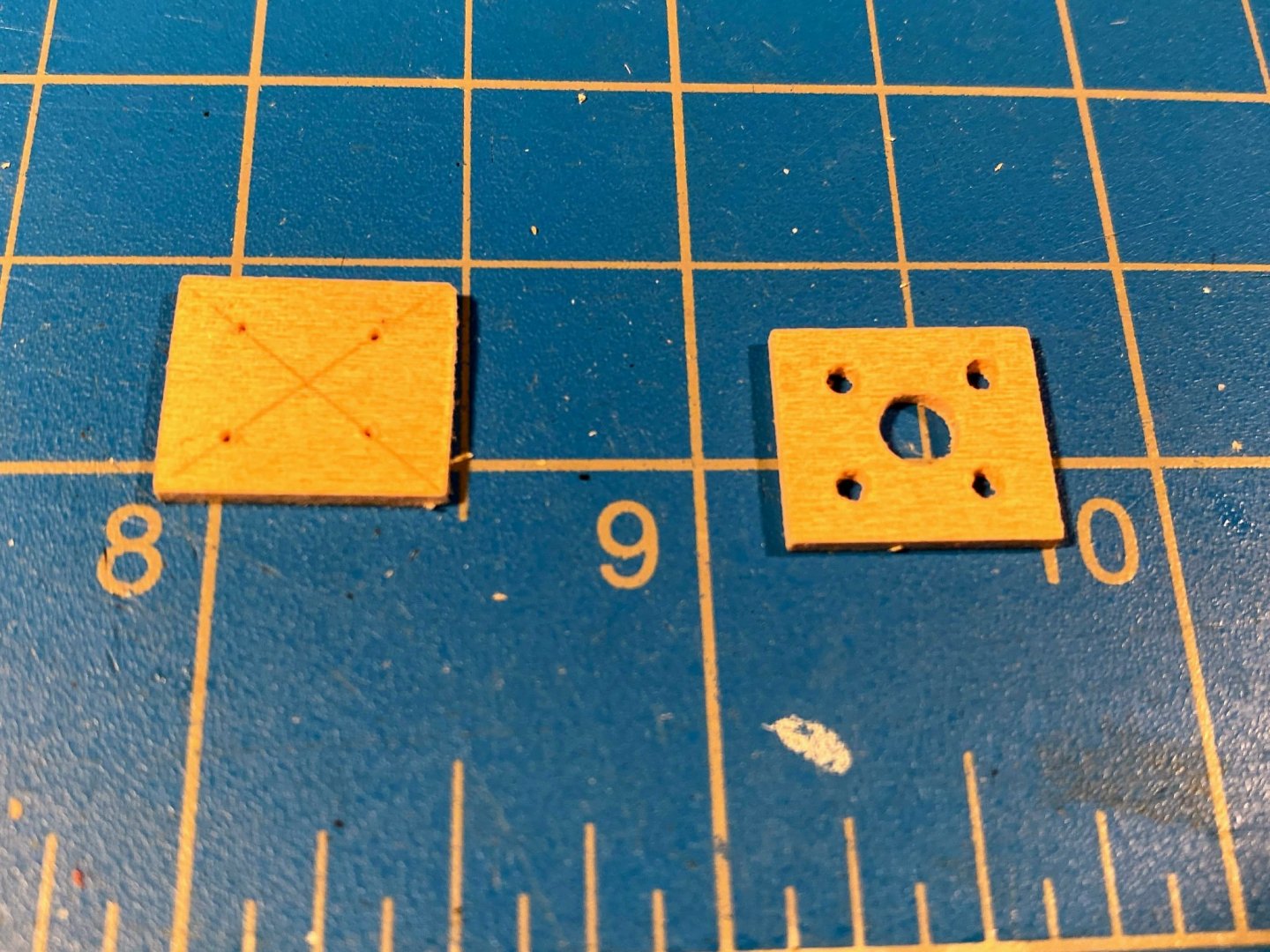
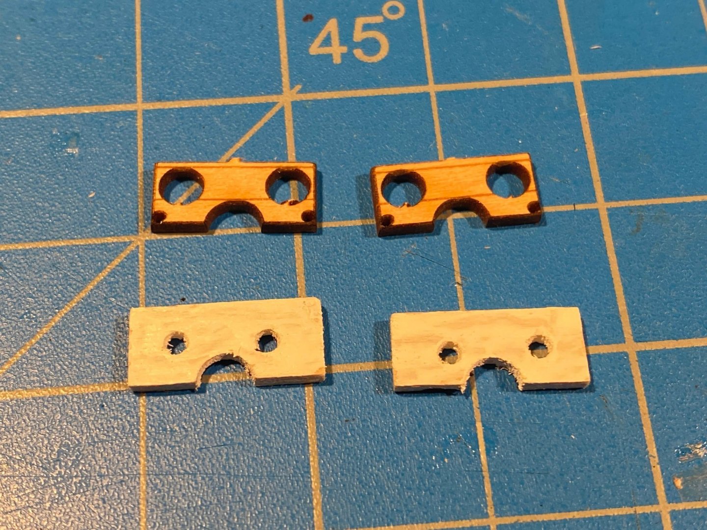
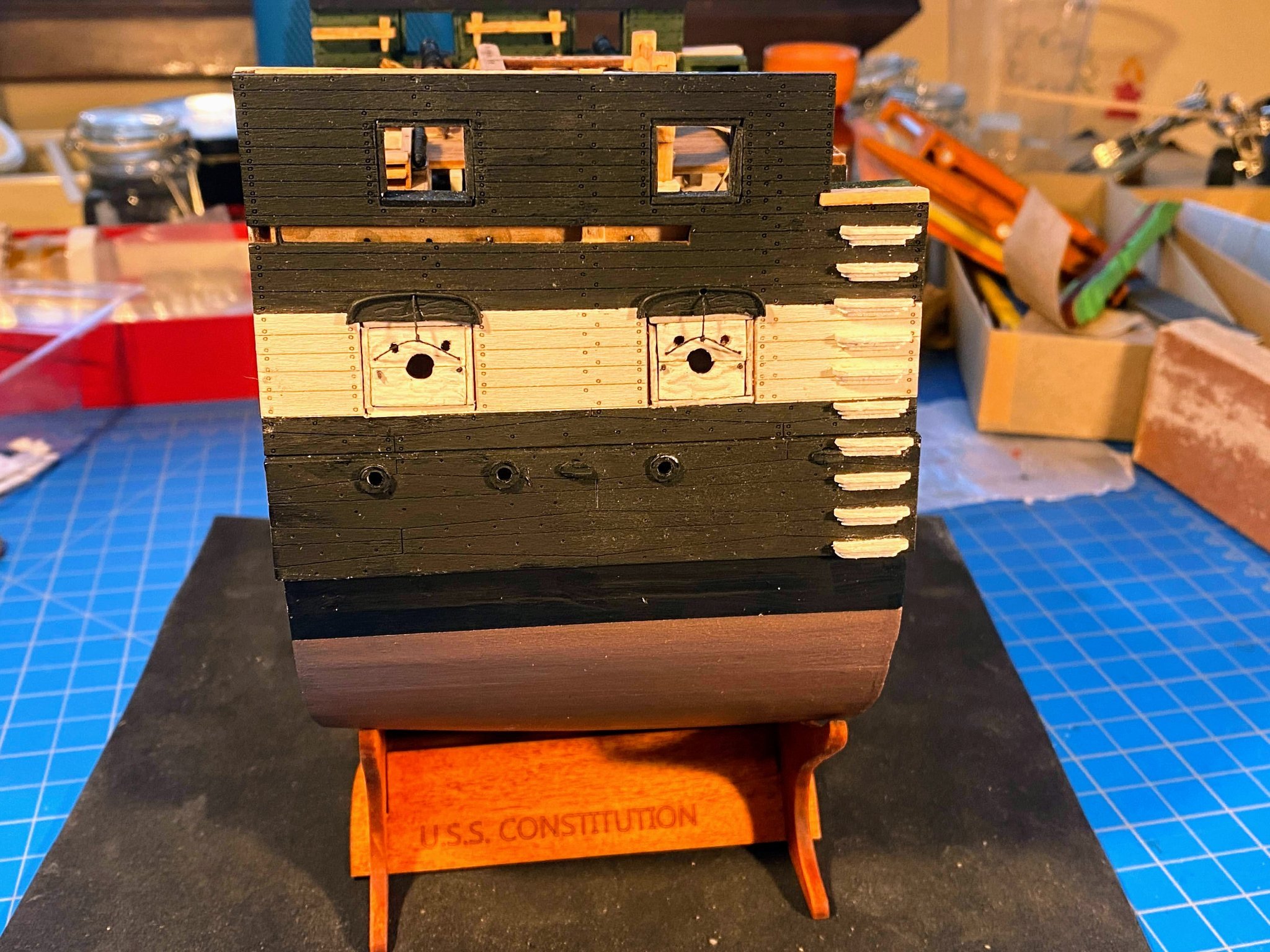
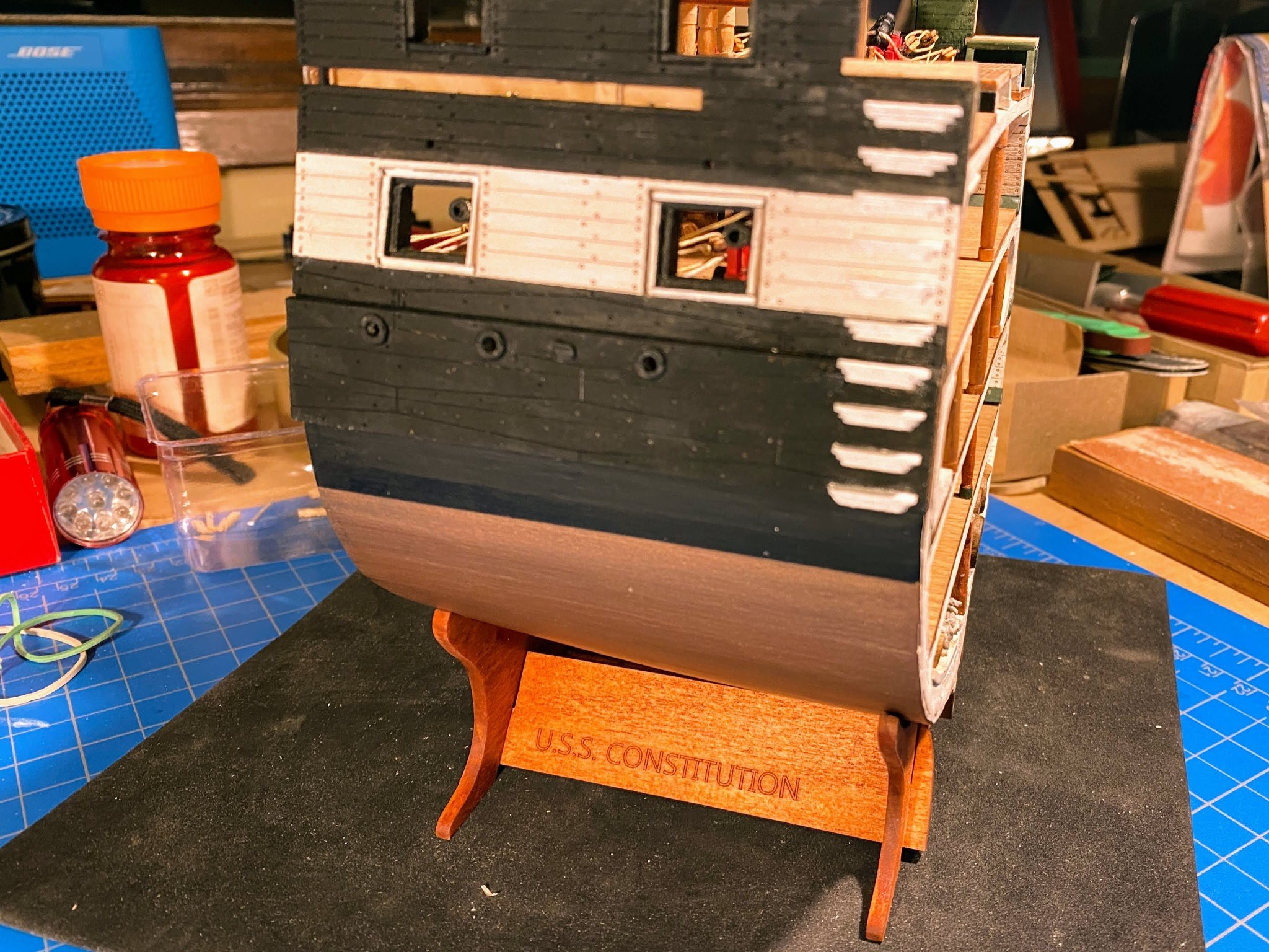
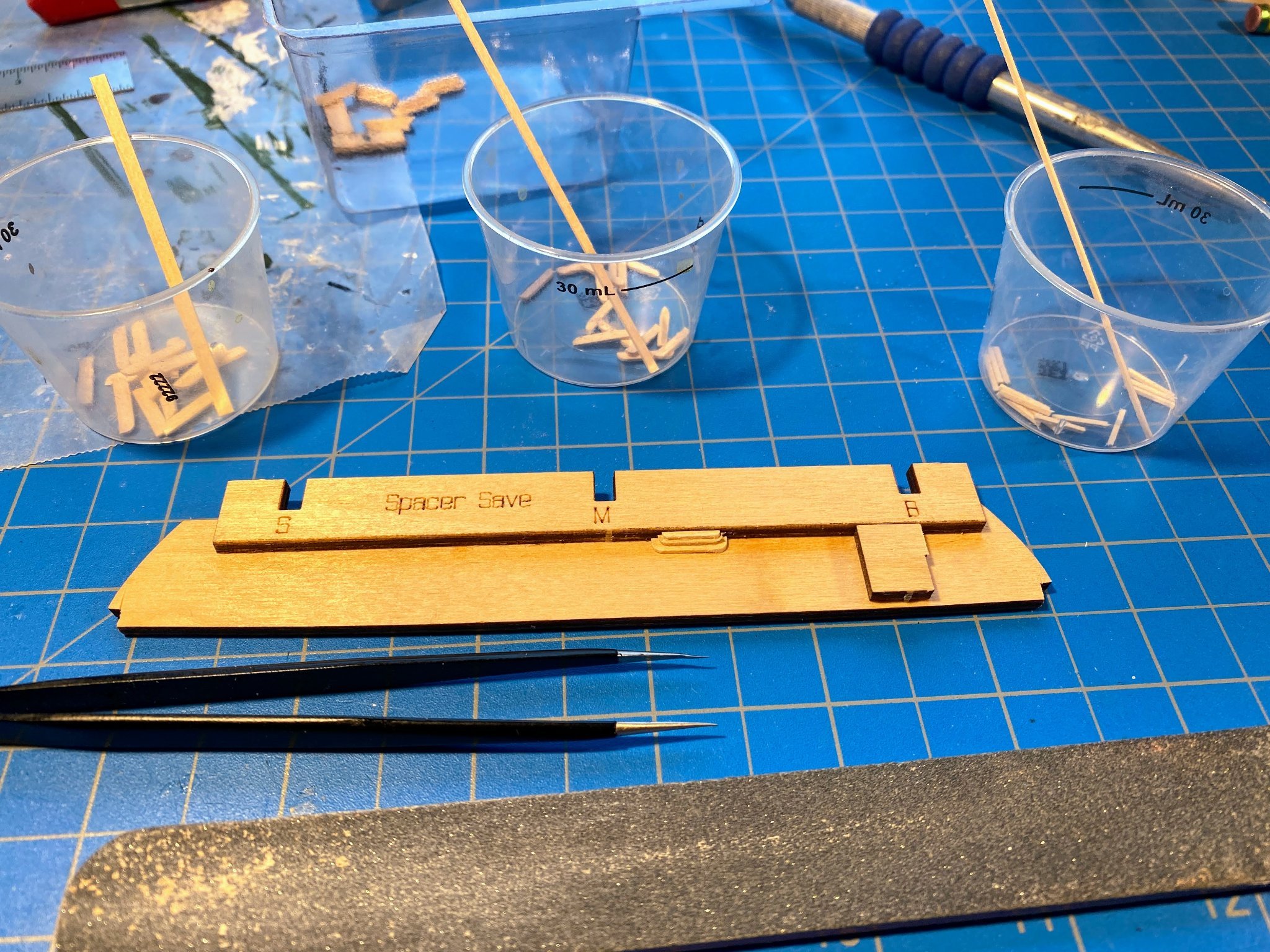
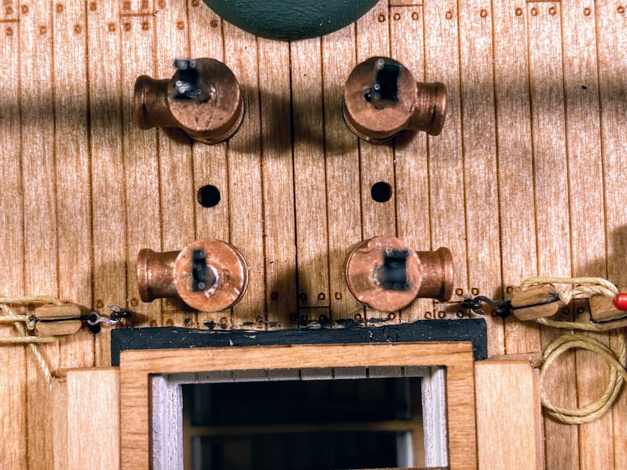


- 163 replies
-
- 6
-

-
- Model Shipways
- Constitution
- (and 2 more)
-
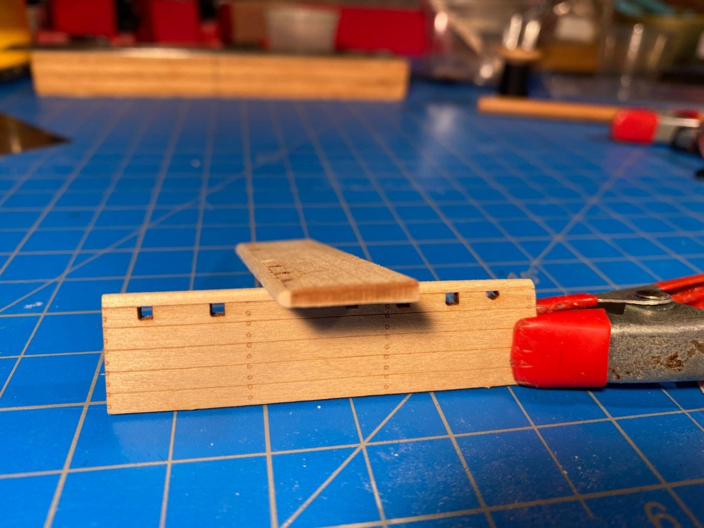
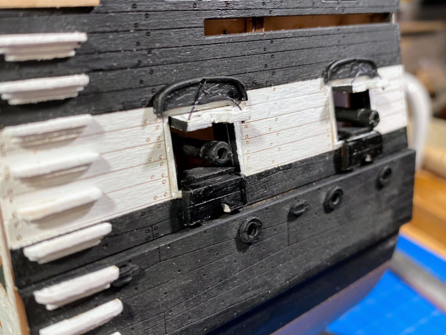
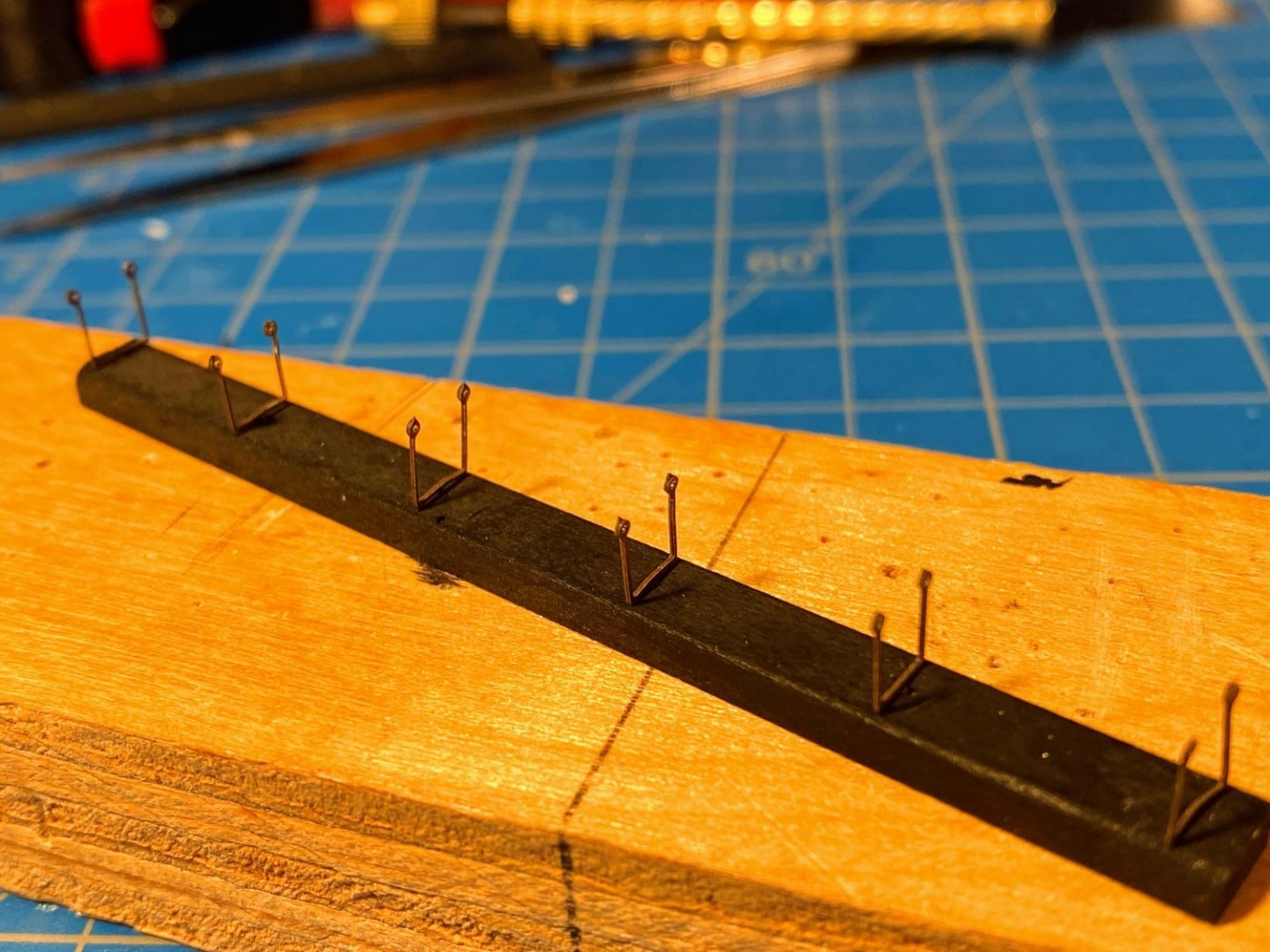
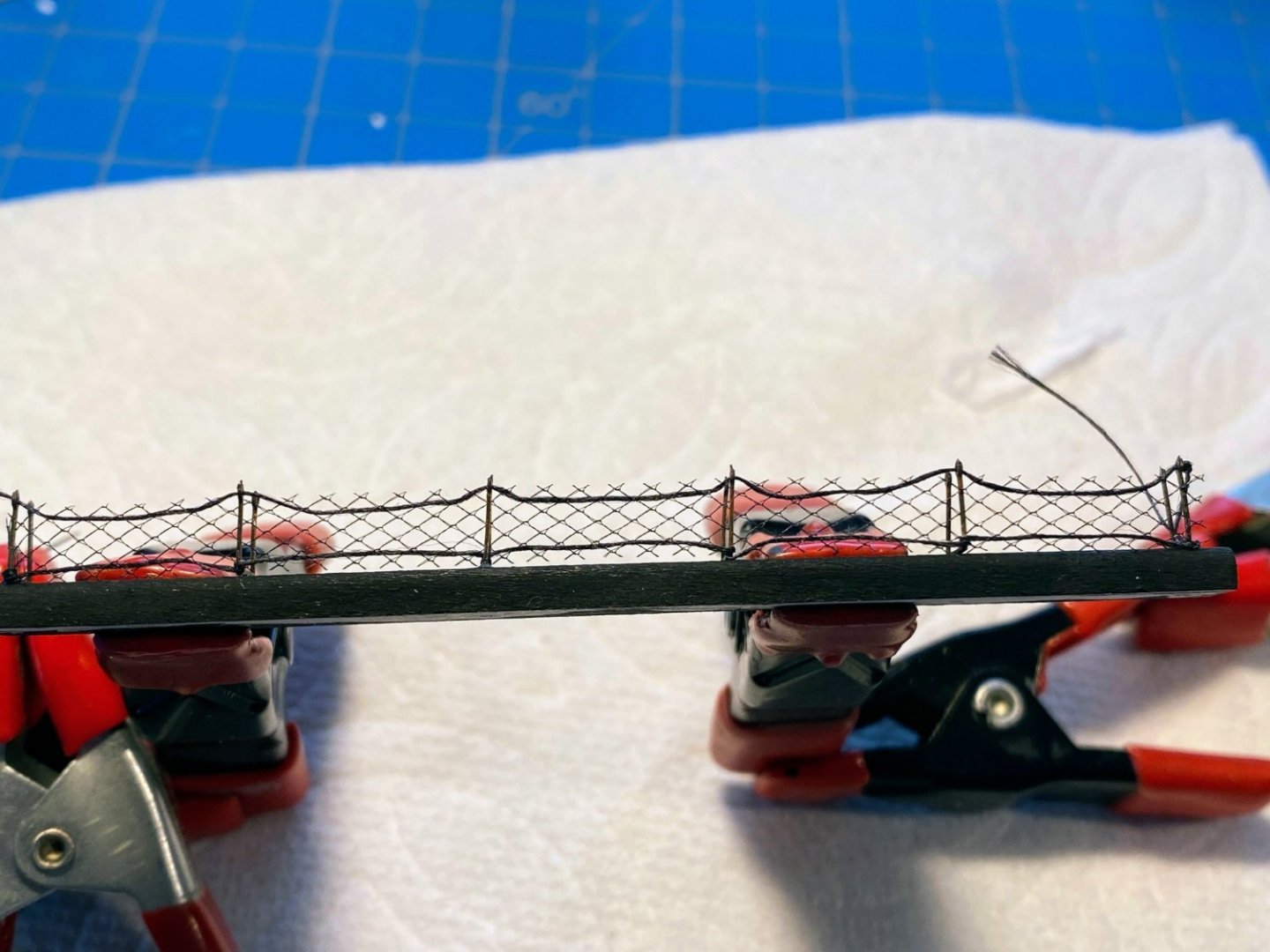
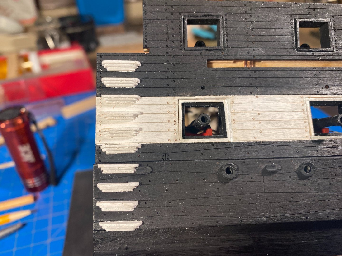
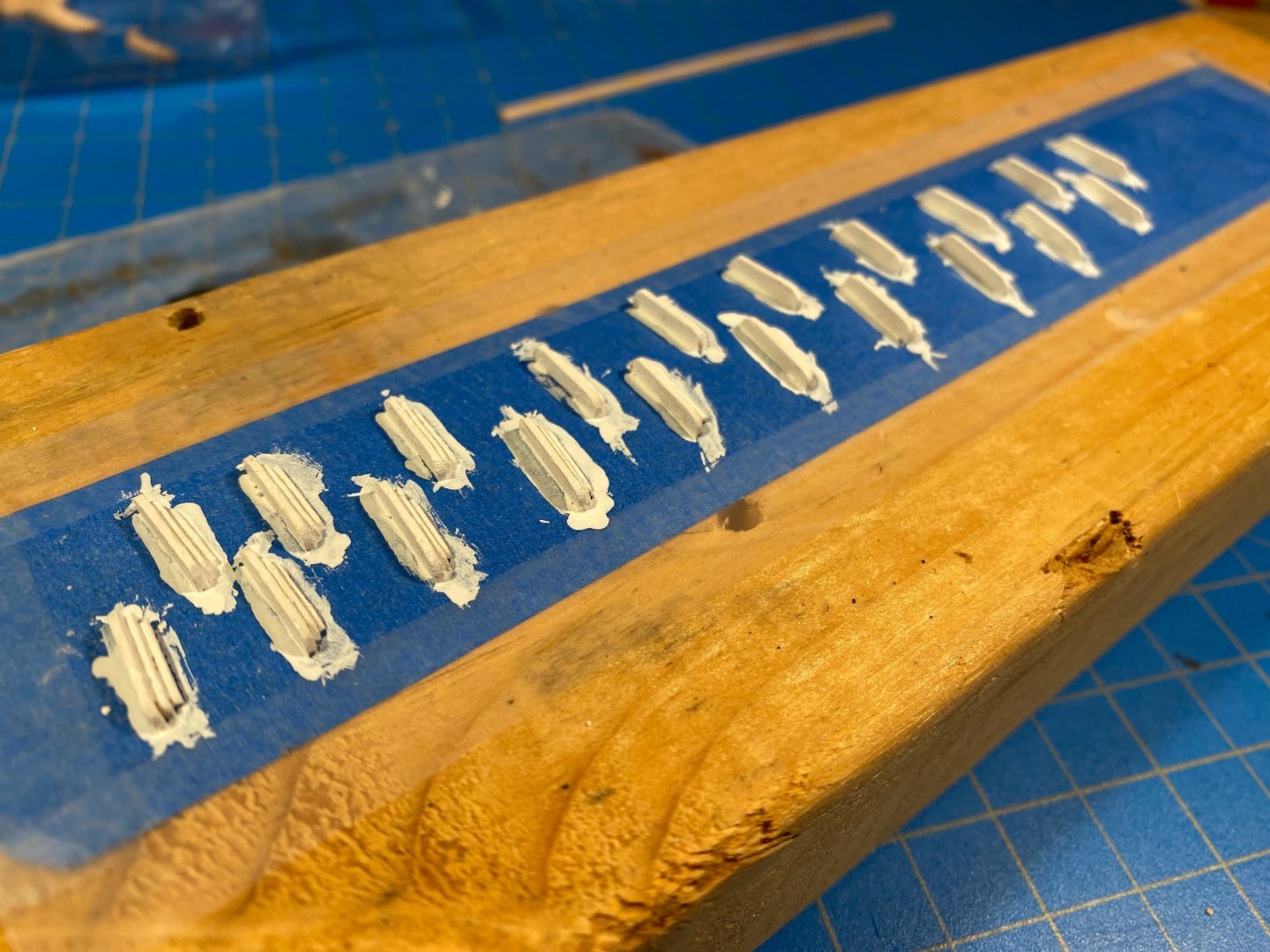
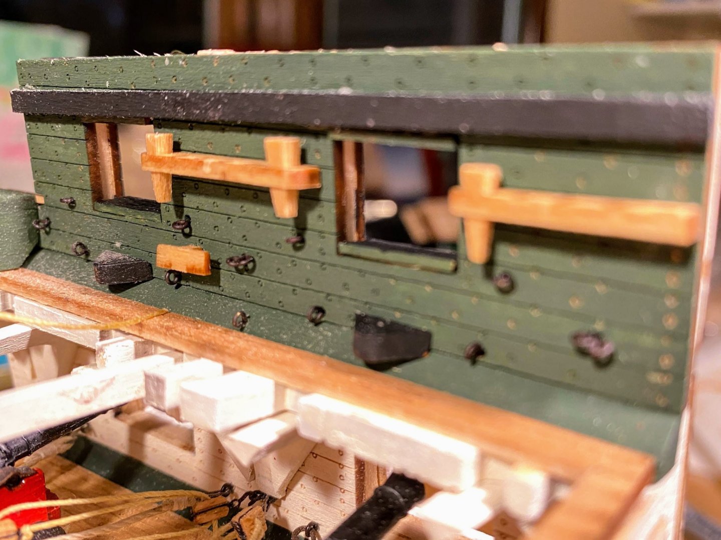
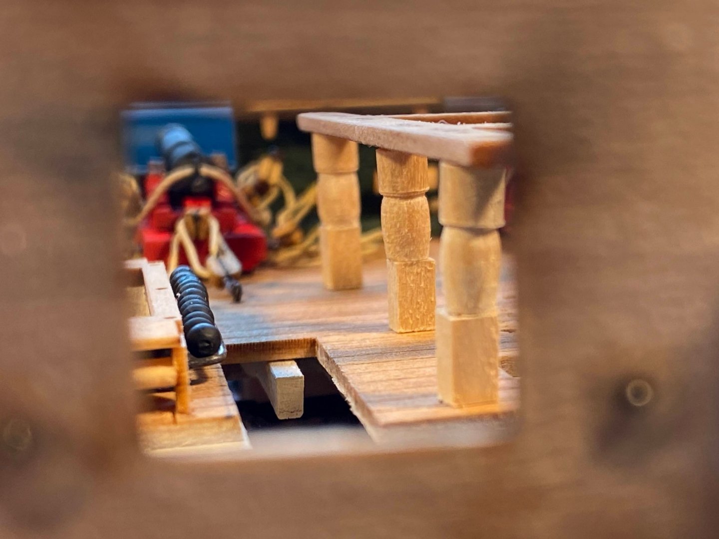
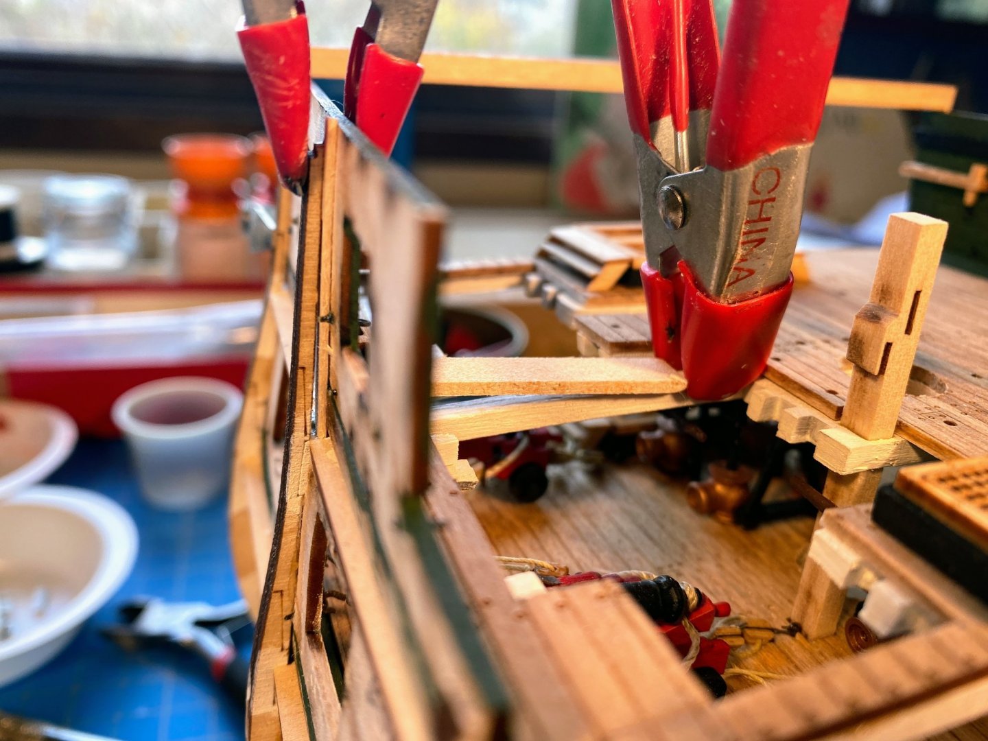
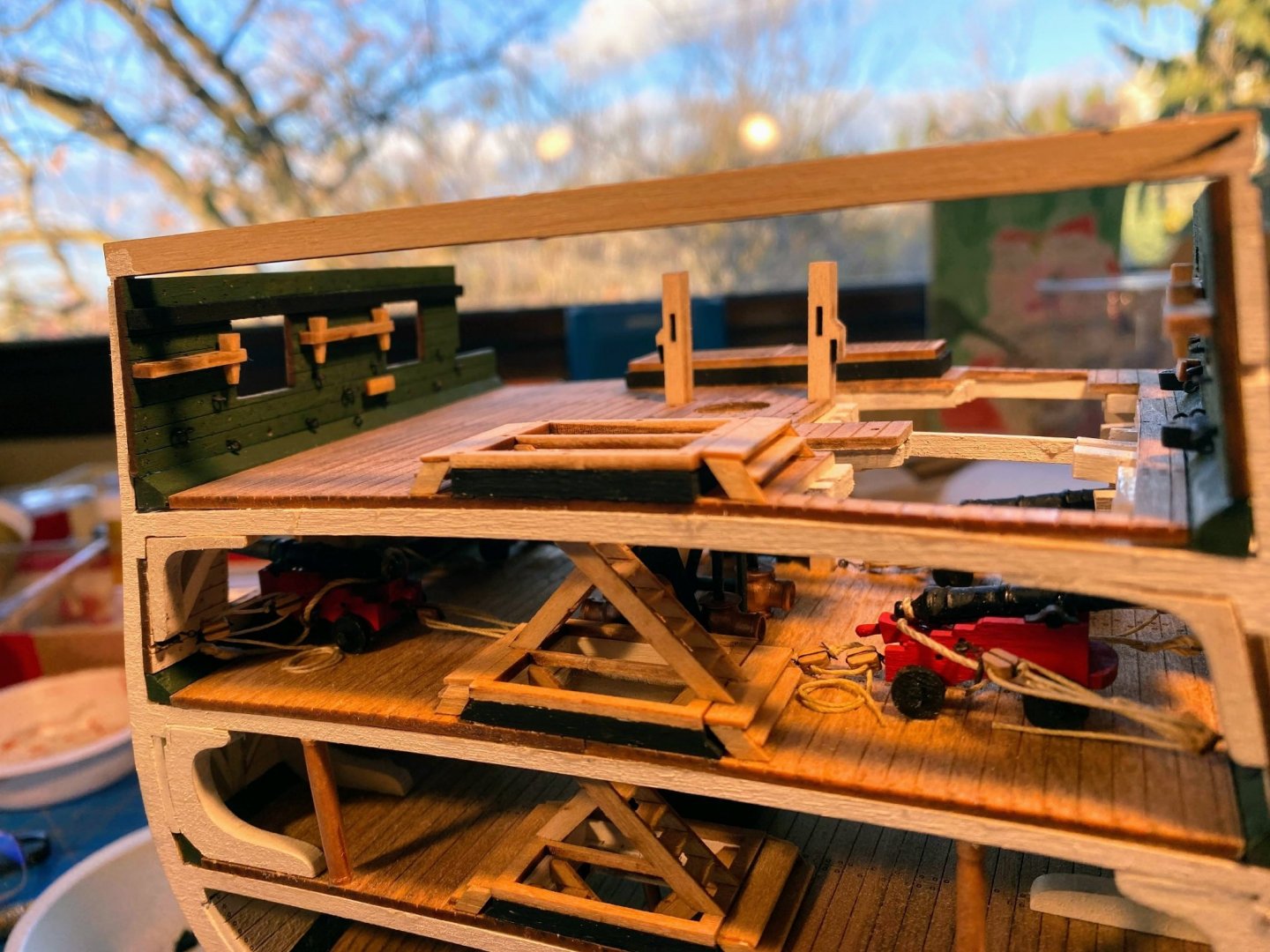
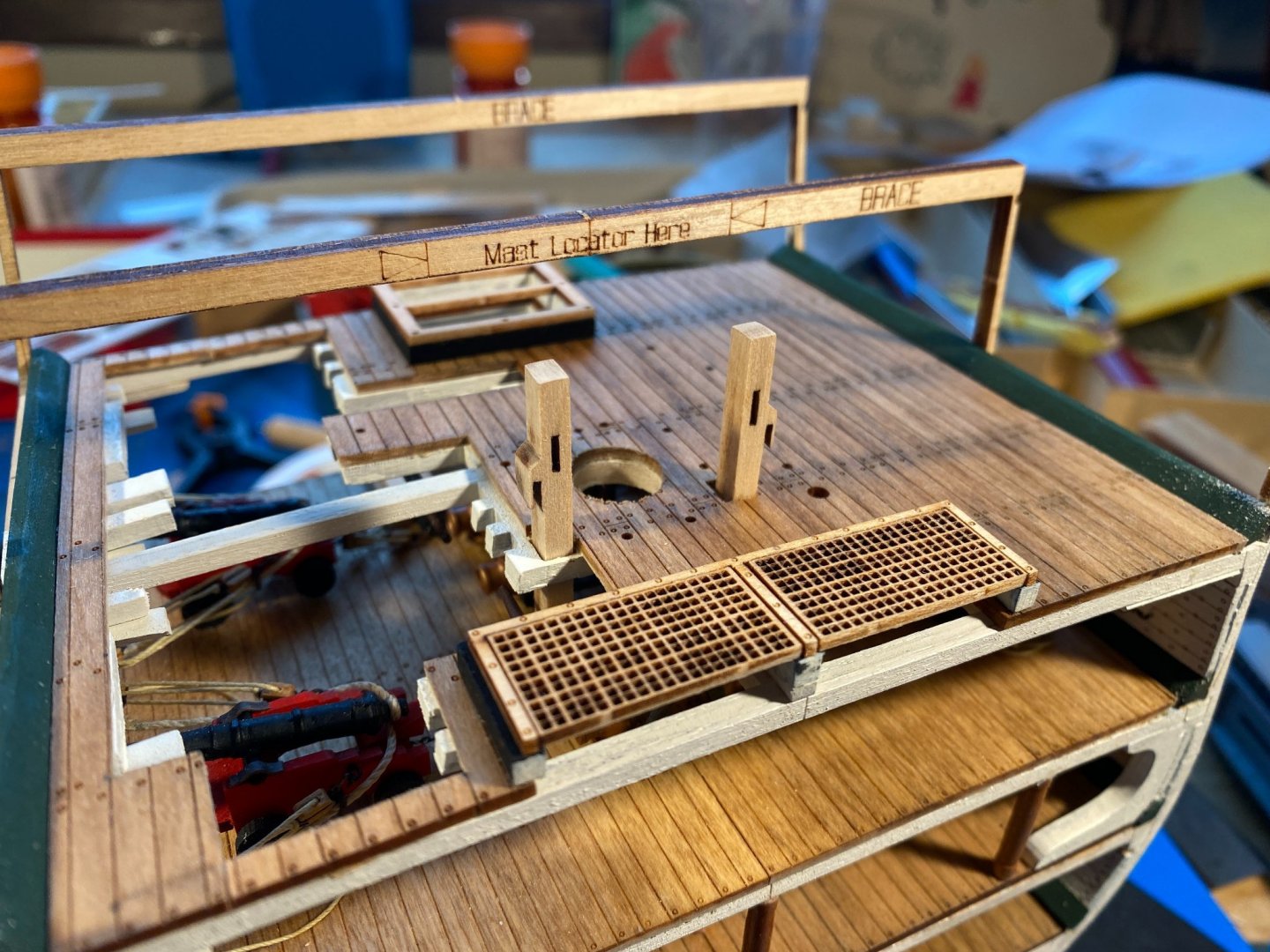
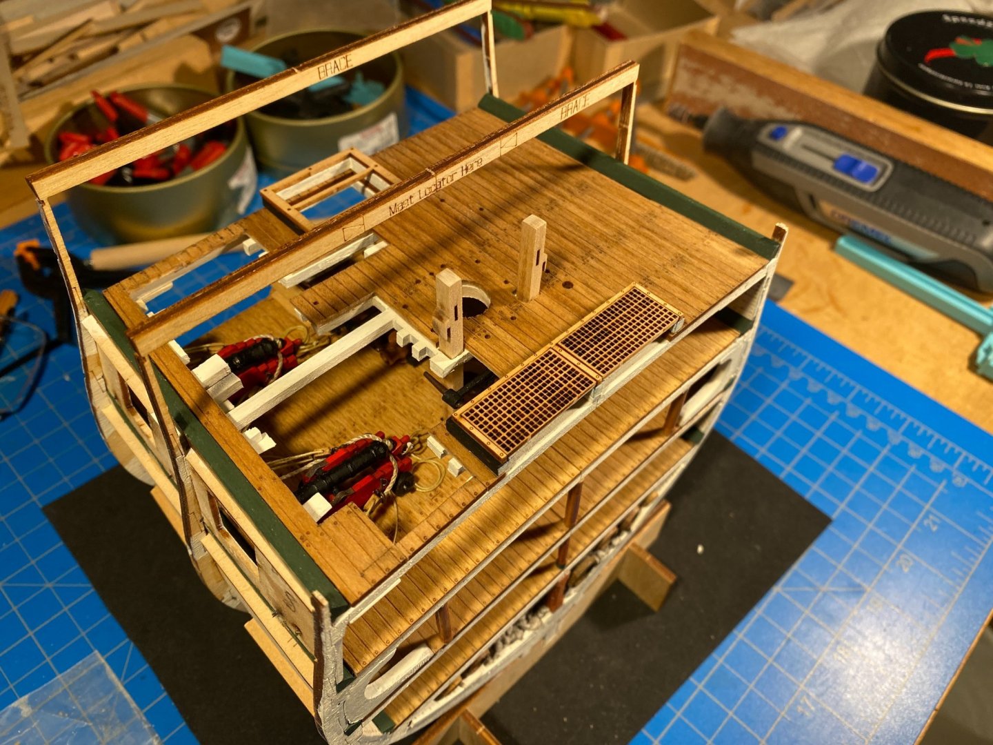
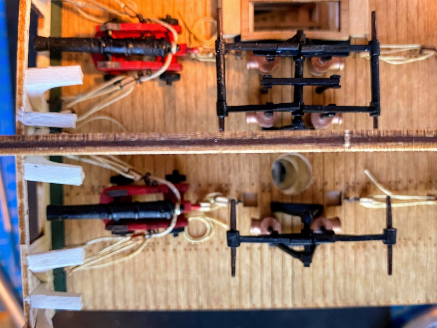
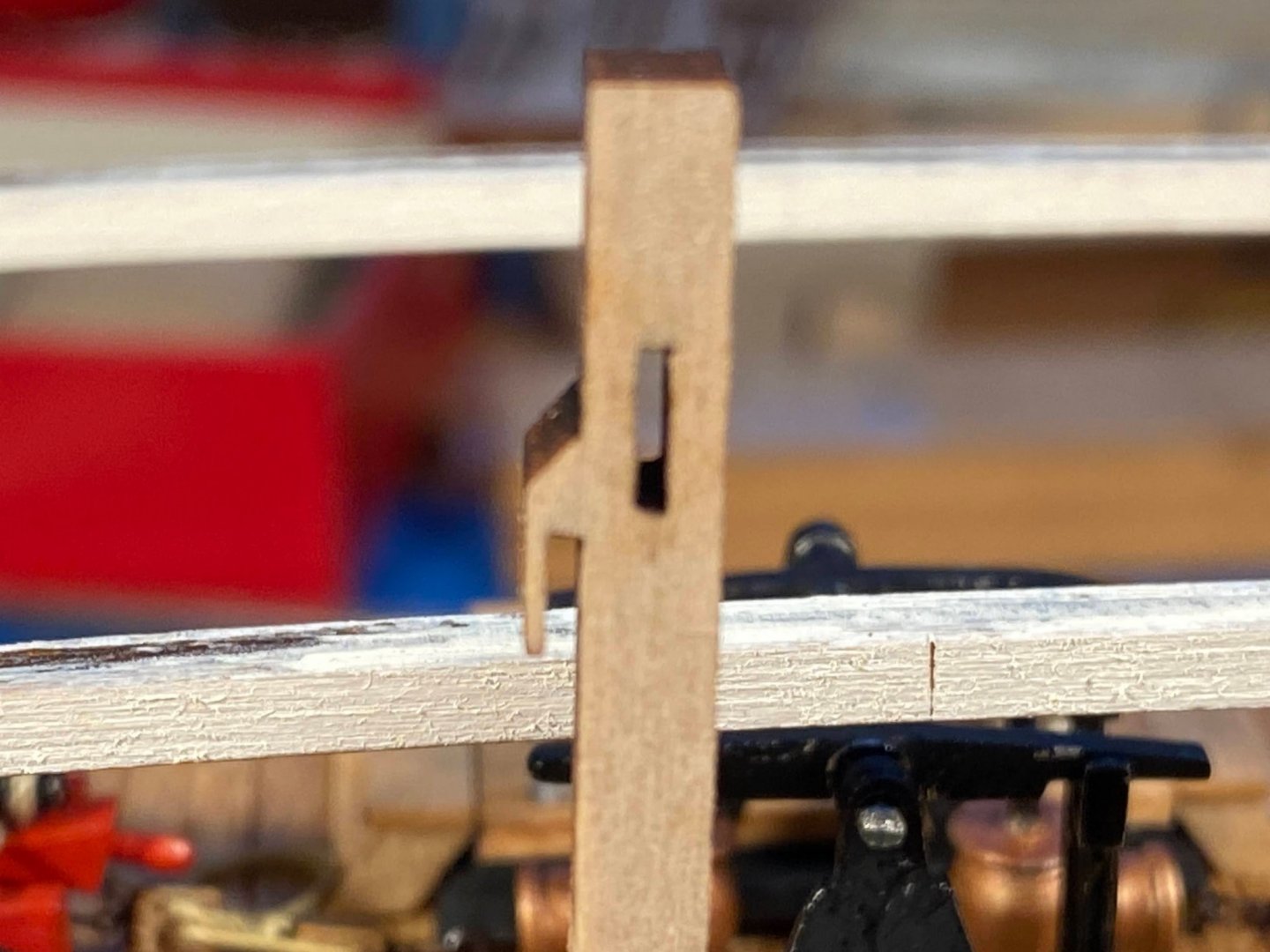
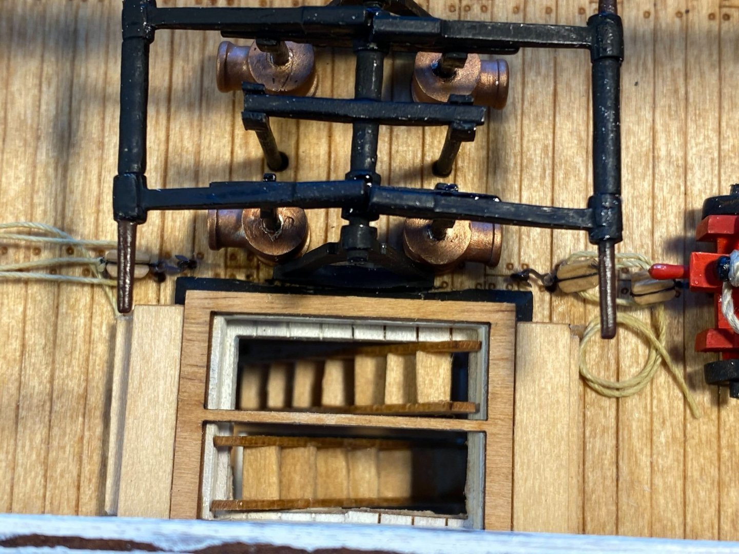
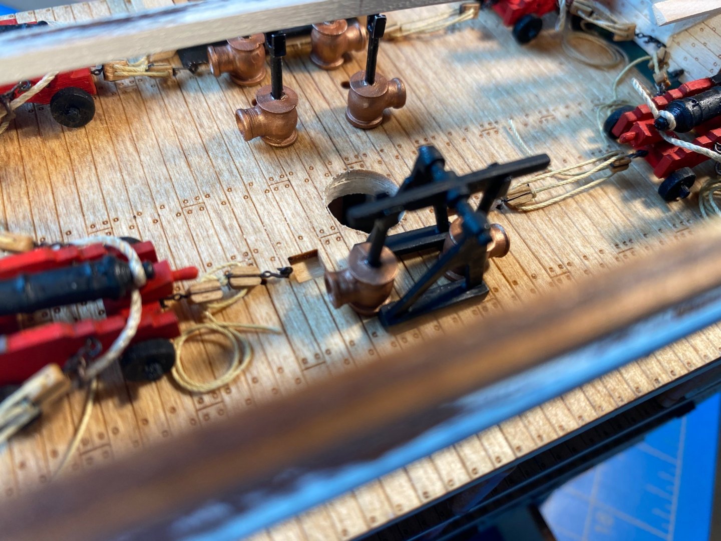
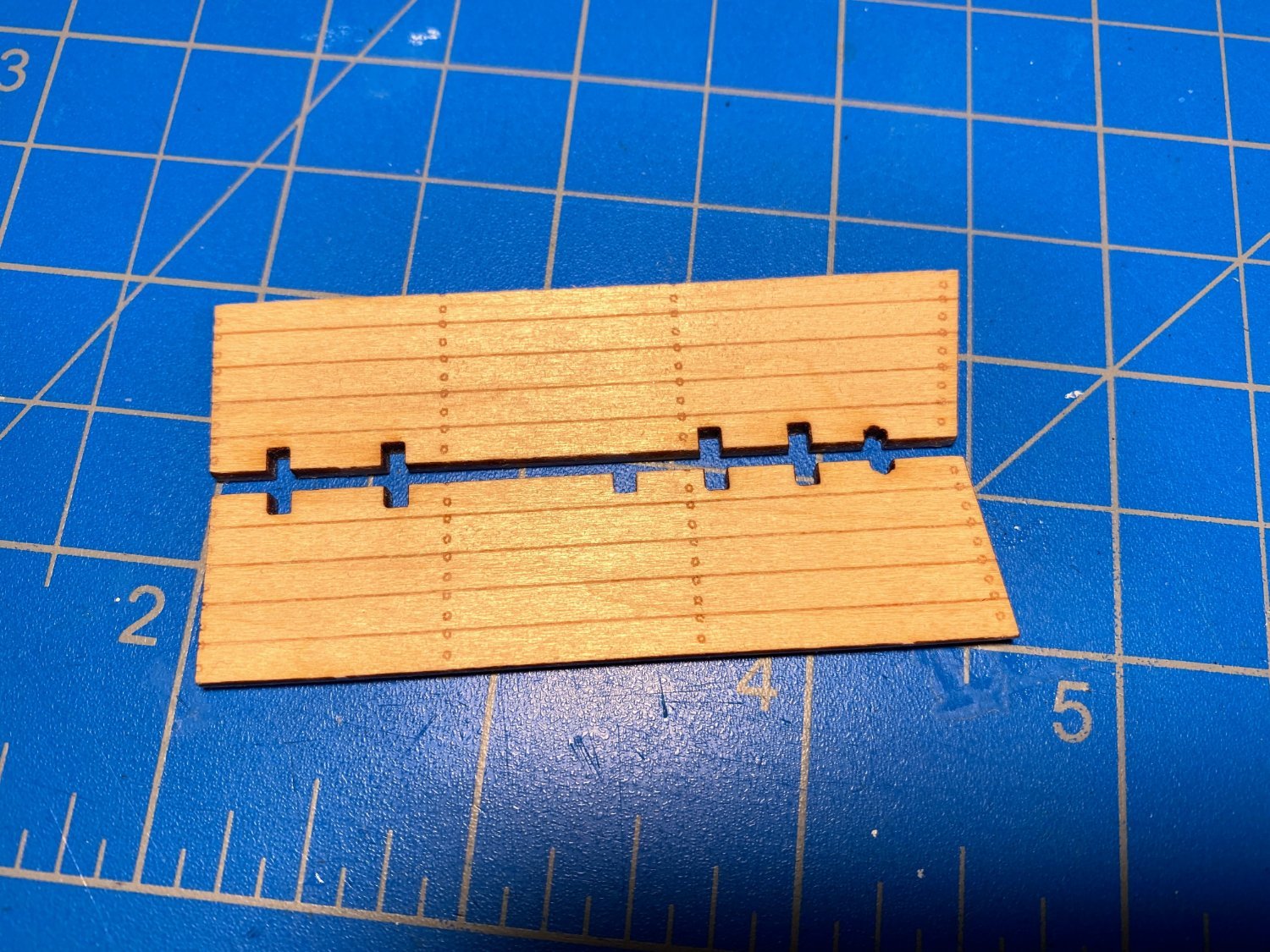
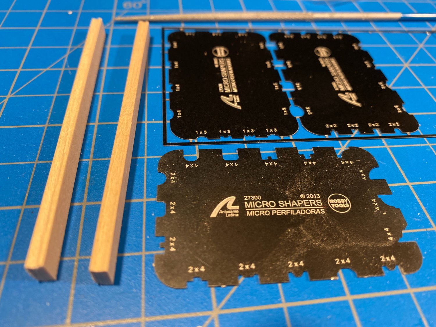
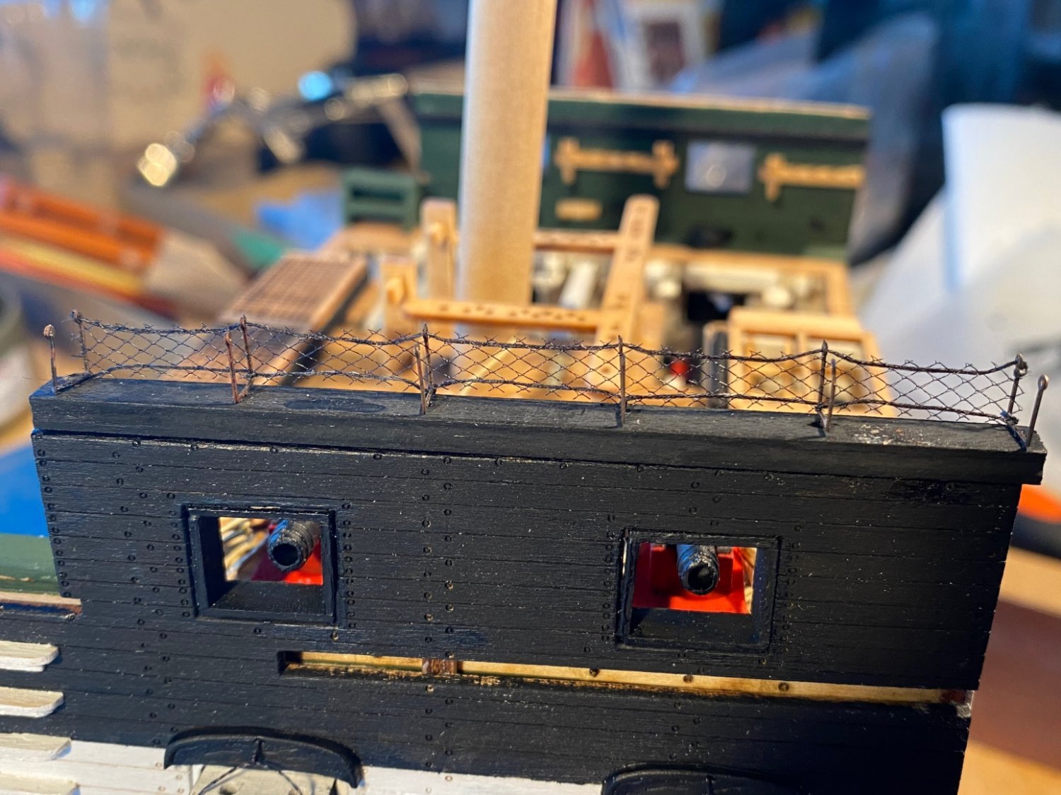
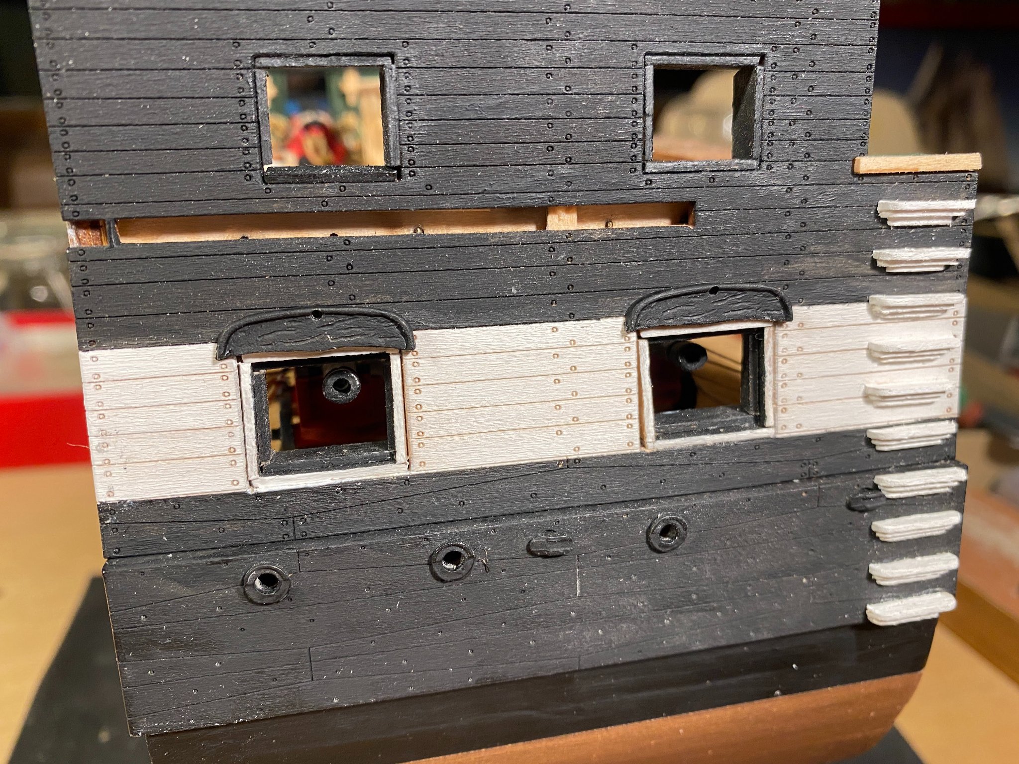
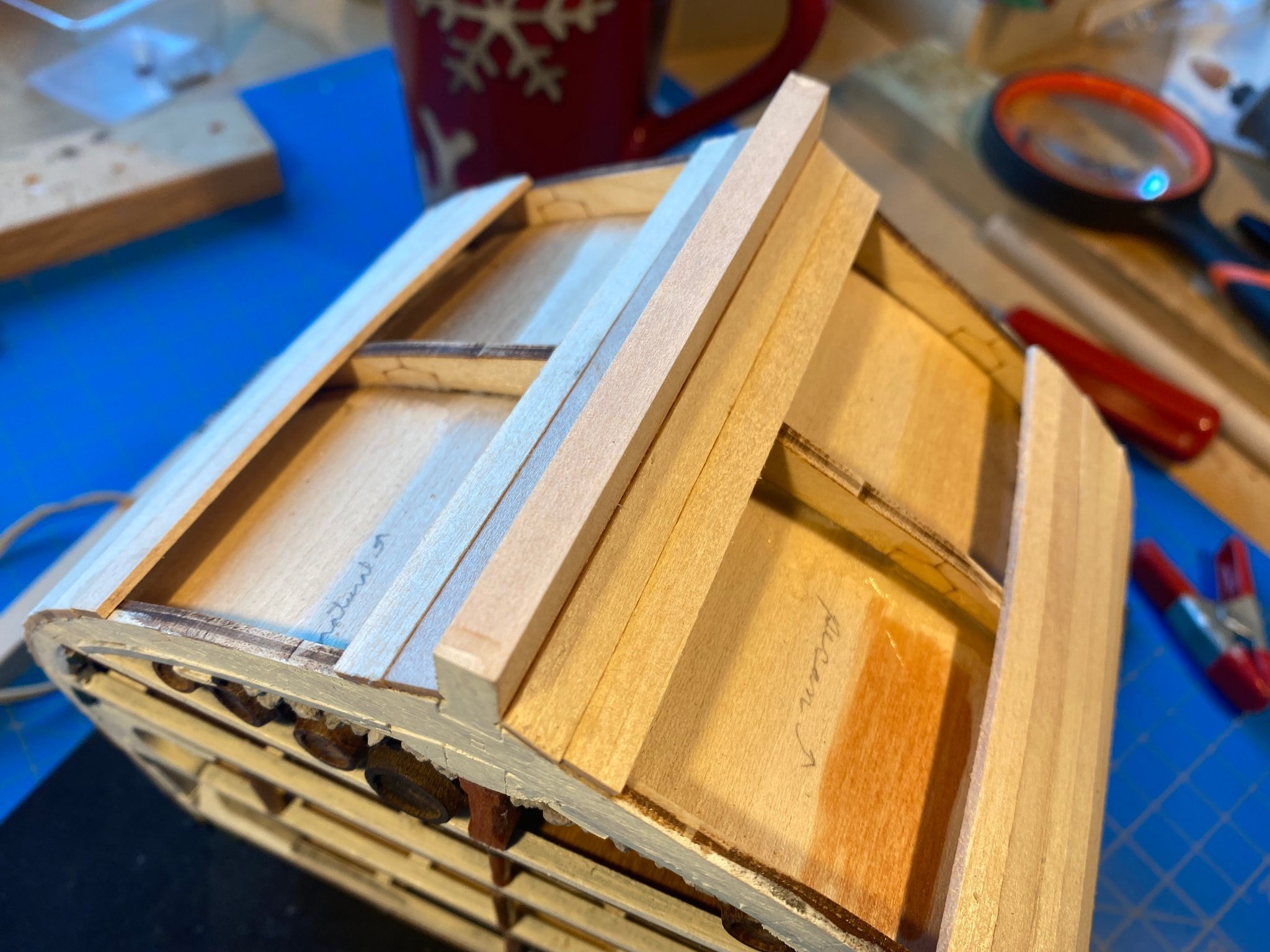
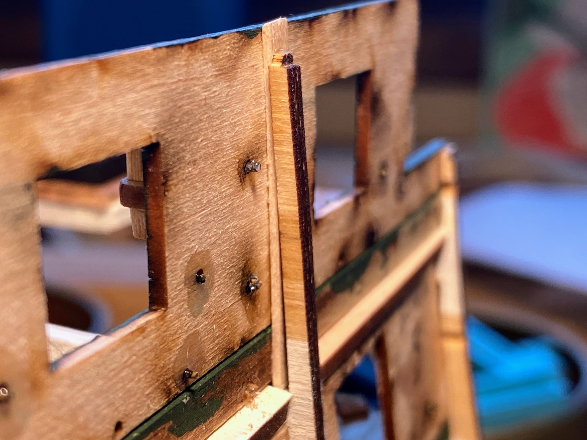
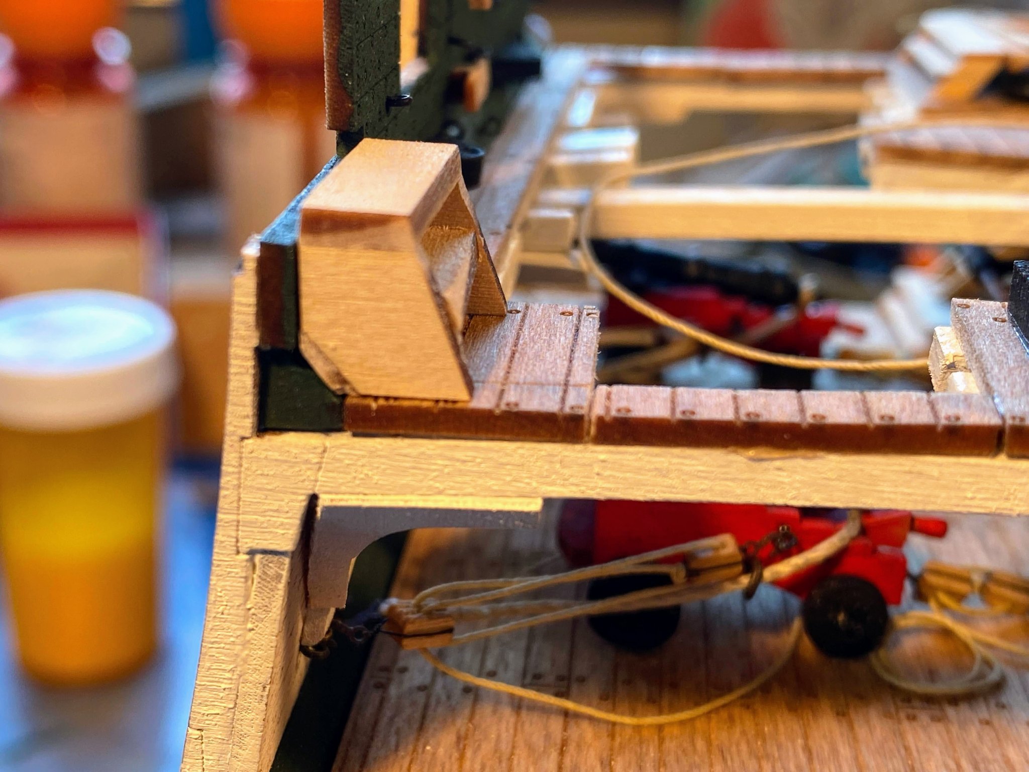
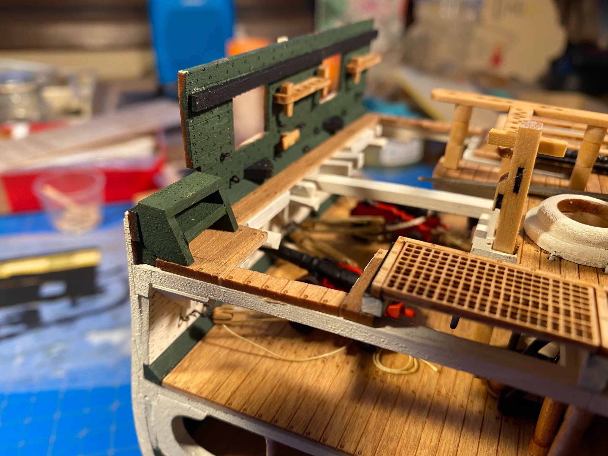
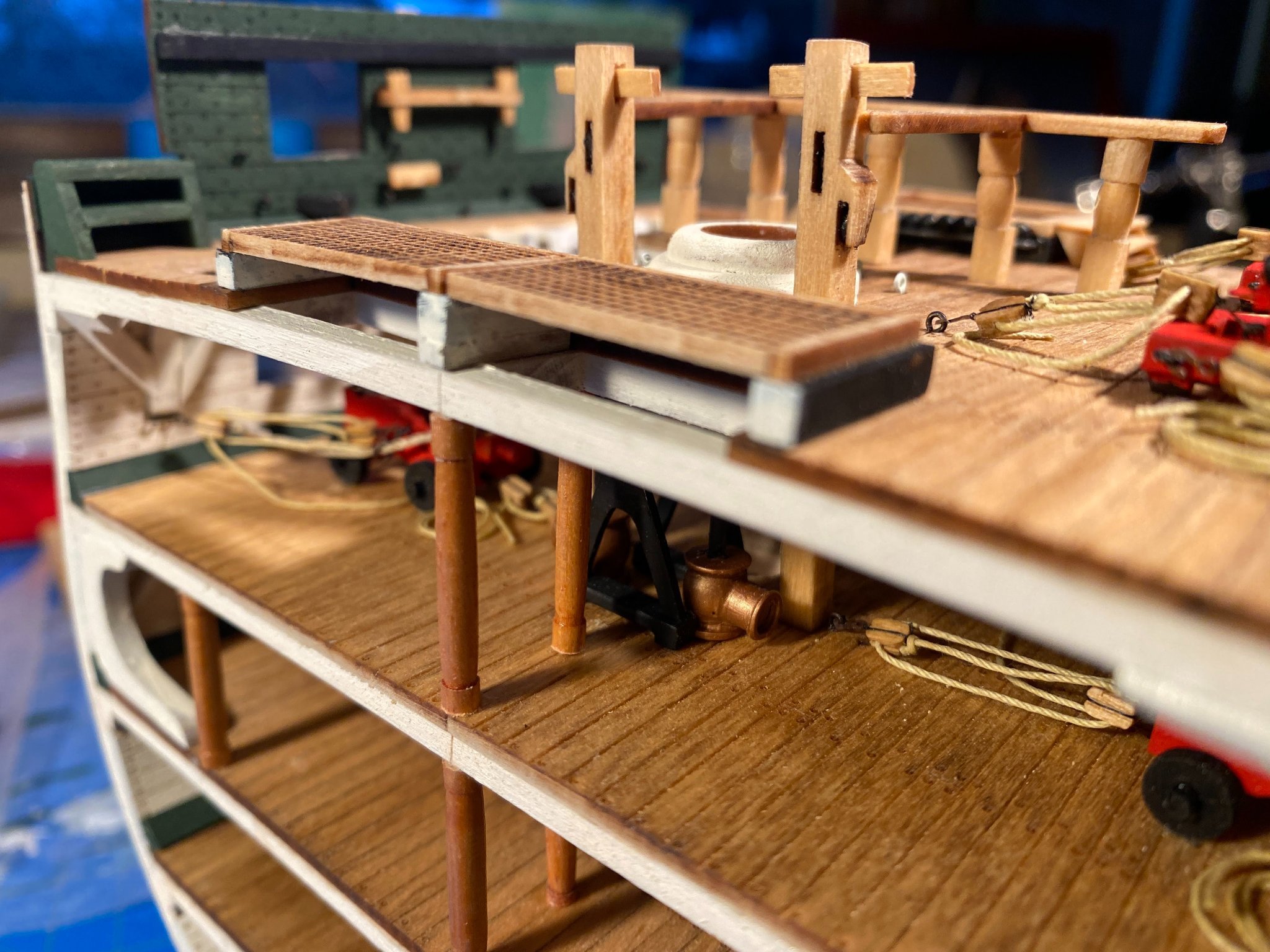
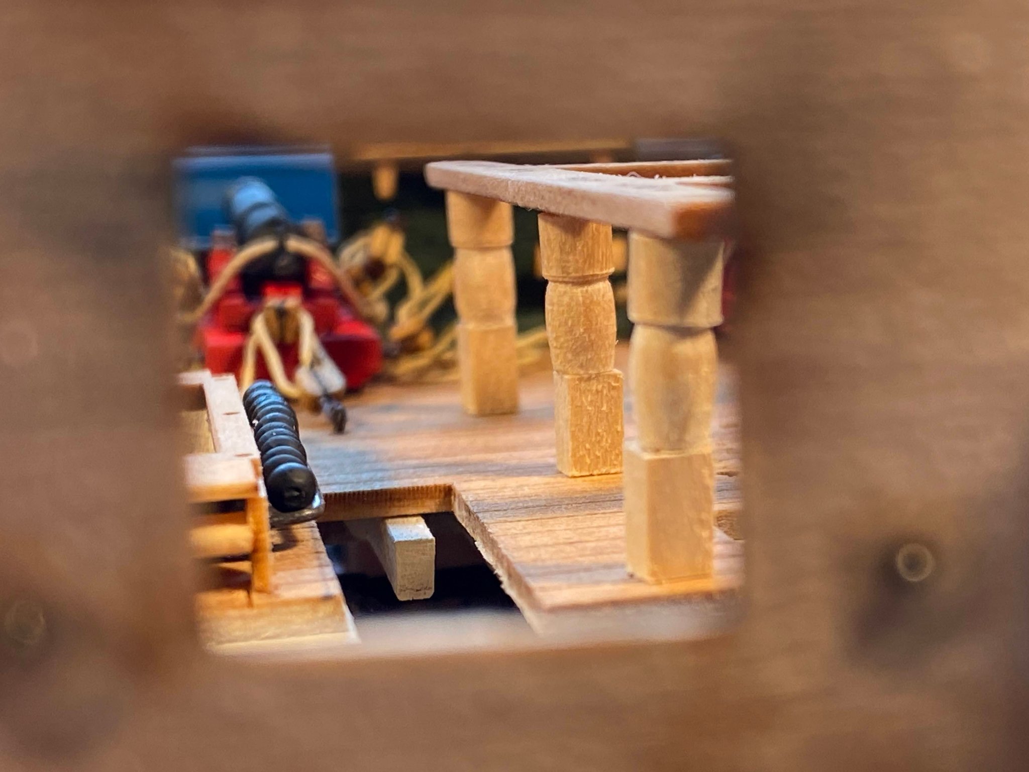
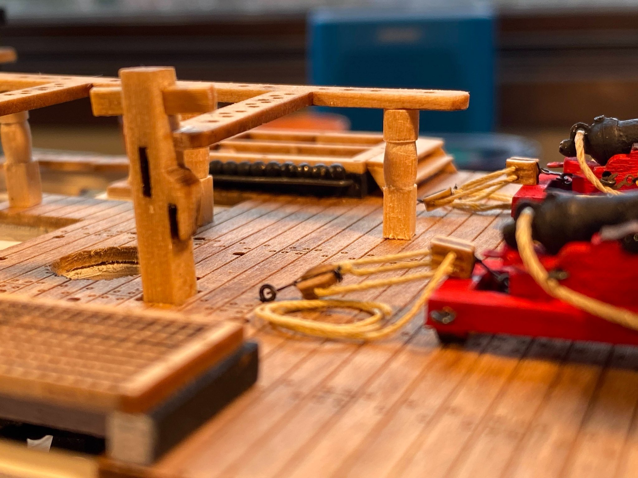
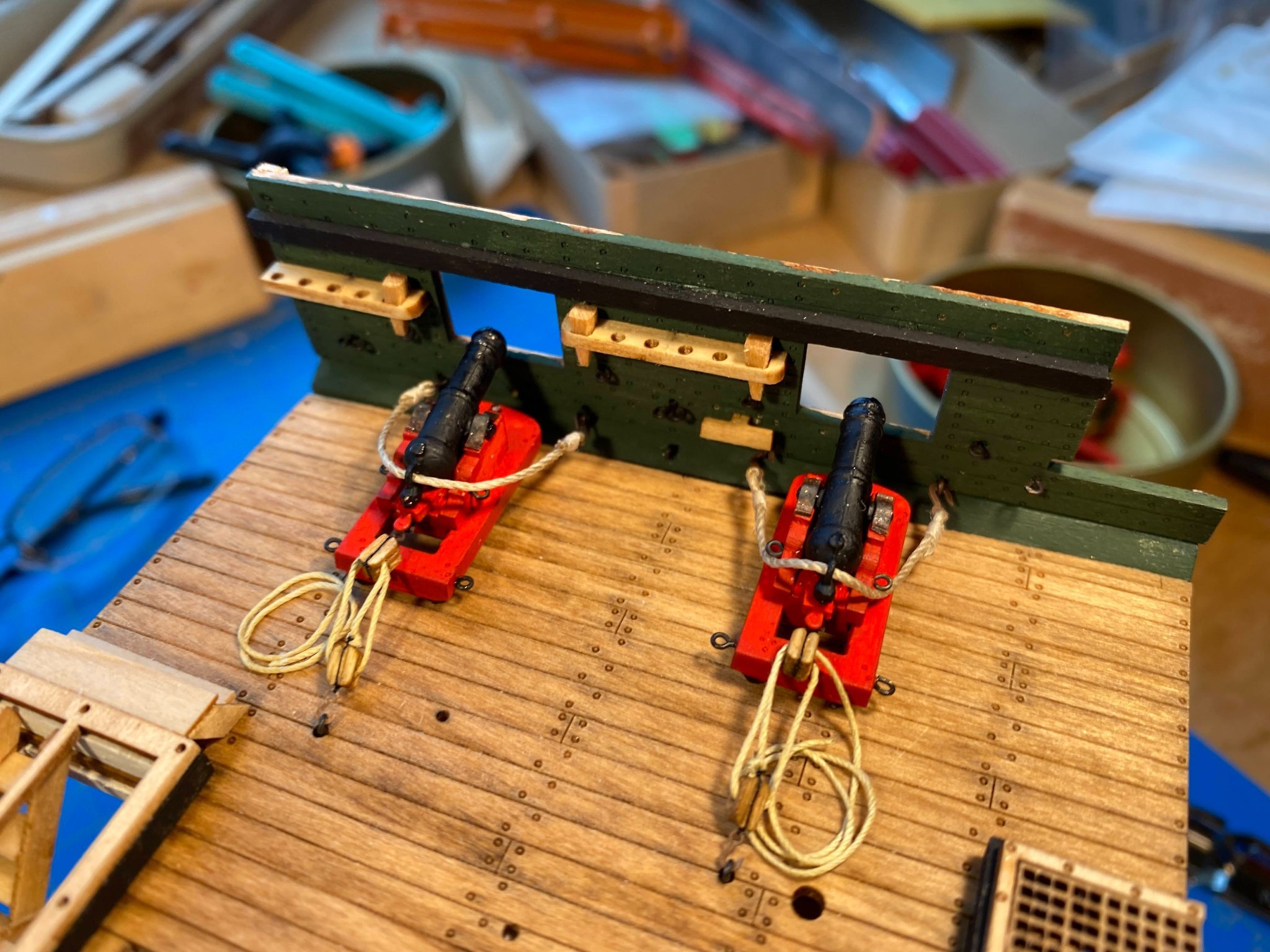
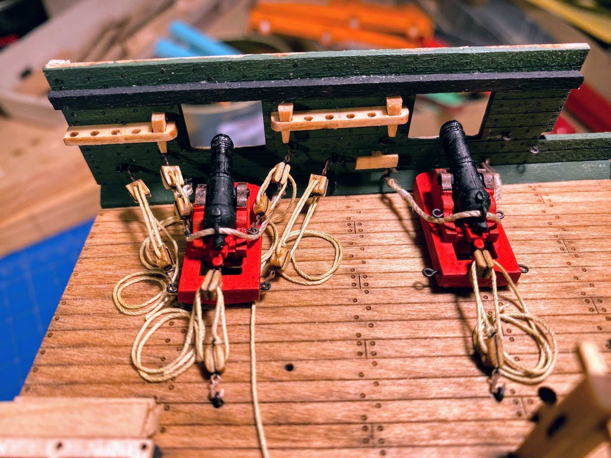
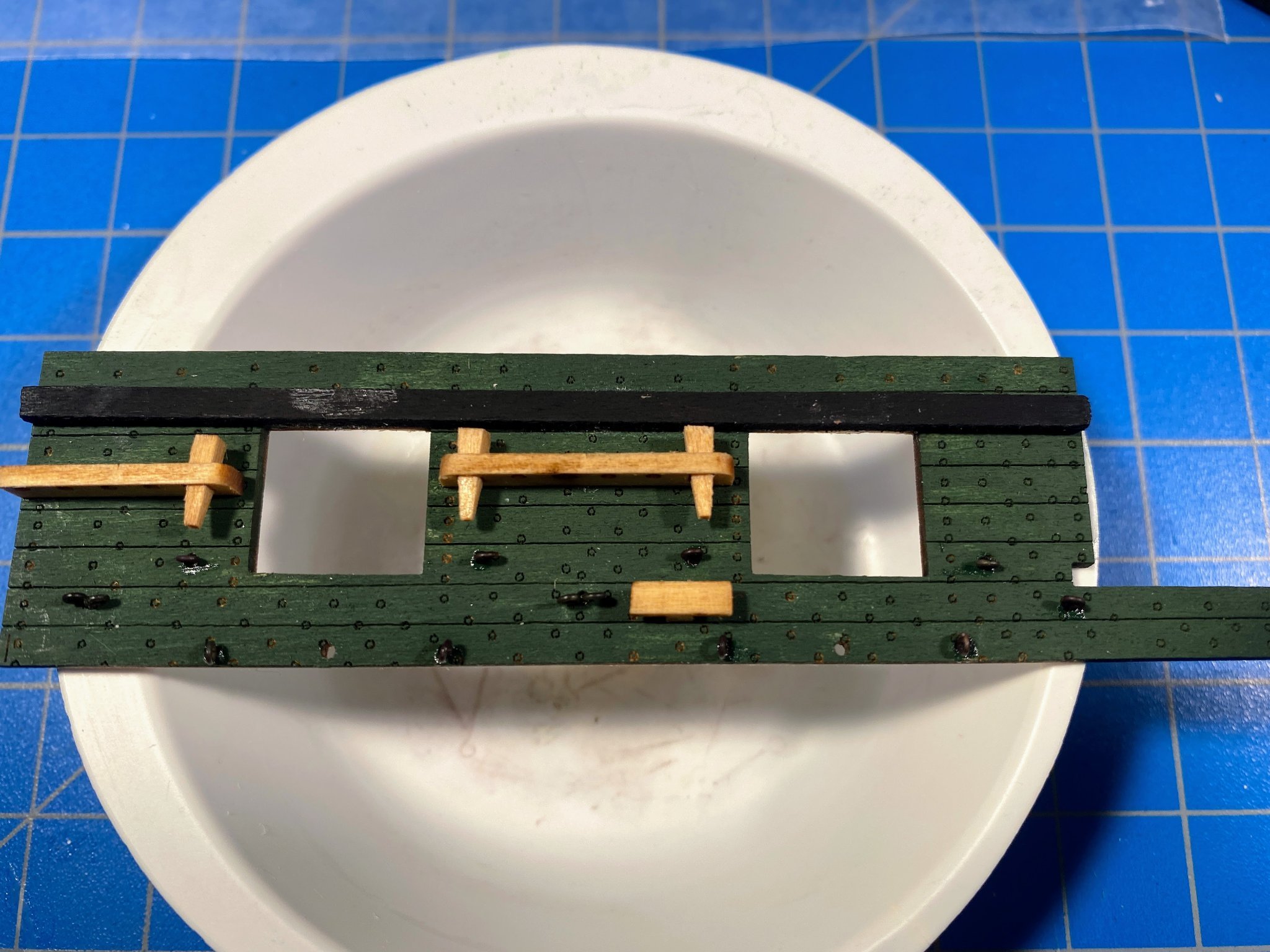
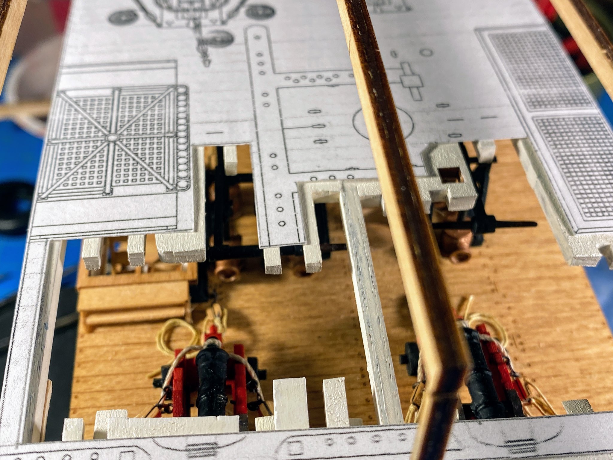
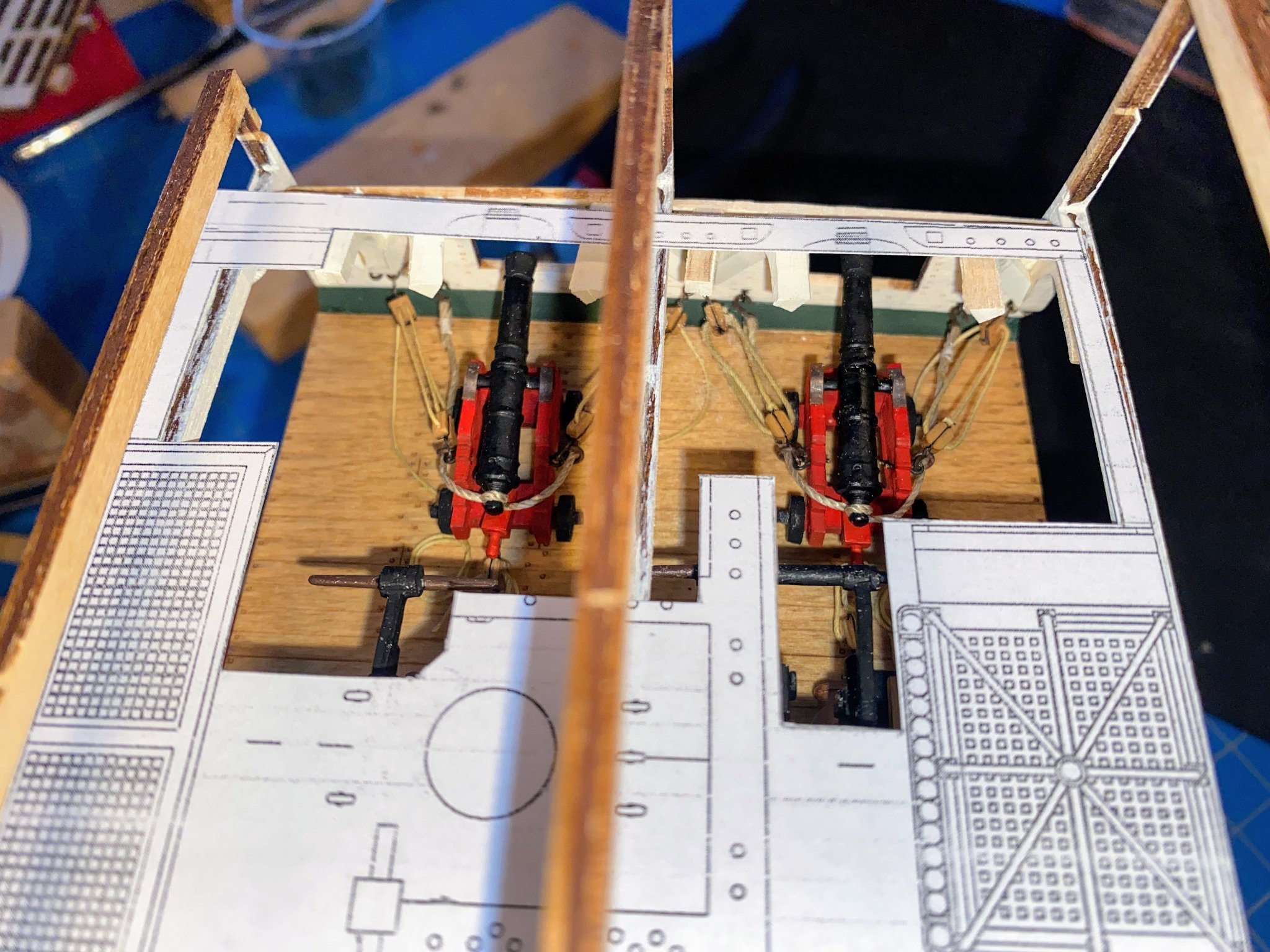
Progress both quick and slow . . . The gun port lids on the port side are displayed open. Putting them together was straightforward and relatively quick. I realized later that I had not put the photo etched brass hinges on the lids on either side, probably in part because they were missing from my kit. I don’t think they will be missed, and who knows, maybe I'll add them later. Next I decided to do the cap rails and hammock stanchions & netting. The cap rails are made from ¼’” x ⅛” strips. The outside edge of each is to be shaped with double half round molding, and the instructions suggest using a molding cutter for that purpose (and a picture of such a cutter is shown several pages later in the instructions, with regard to the channels). The only cutters I could find are made by Artisanea Latina. I purchased a set and gave it a try. Unfortunately they are all made for metric sized wood strips, and keeping a US measured strip centered in the desired form was a bit of a challenge. But it worked pretty well, but a bit out of focus in the photo below. Installing the stanchions on the caprials was pretty straightforward. Fortunately as described further below, I had the foresight to enlarge the holes in them before gluing them onto the cap rail. The netting was next, and it was anything but straightforward. I looked at logs of a few whole-ship Constitution builds, and discovered others found the netting to be challenging (including GrandpaPhil, an occasional visitor here, on his Victory). After consuming many more hours than it should have, I completed one of four sides of netting, and I’m not entirely satisfied with the result. Here are a few things I learned or figured out in this effort, which may be helpful to others: The instructions suggest using 34 gauge wire to simulate the rope which links the stanchions together, but none of the supplied wire or wire I already had was thin enough to get through the holes even after enlarging. And using wire to simulate rope seems kind of counterintuitive anyway. I used a 76 gauge drill bit to enlarge the holes in the stanchions, the smallest bit I had that resulted in a hole large enough to get thread through. The drilling had to be done manually with a pin vise and done very carefully to avoid having the bit get stuck and twist the top of the stanchion off. The instructions have you do the netting after gluing the cap rails (with stanchions) to the top of the bulwarks, but I assumed correctly that I would need to approach this task from a lot of different angles, and that wouldn’t be possible once the cap rails were glued in place. I also decided that I won’t glue the cap rails in place until late in the build, after most of the rigging is done, to avoid constantly snagging the rigging on the cap rail/hammock assemblies. The instructions have you glue the netting to the wire (or in my case thread) with tiny drops of CA glue. In my experience even the tiniest drop of CA spreads all over the place and tends to make a mess. Furthermore, it’s usually quite visible after it dries. I much prefer diluted white school glue, because although it too spreads all over, it’s virtually invisible after it’s dry. The downside is that it’s nowhere near as strong as CA, and I doubt that using it to try to glue netting to wire or thread would be sufficient. I thus tried to weave the thread through the diamonds in the net. Putting something white behind what I was doing helped immensely in being able to better see the thread and netting. I used a metal ruler and a knife with a new blade to cut the netting, but I wasn’t careful enough to avoid leaving bare ends of netting (rather than cutting right at the top of each diamond), which are like fishhooks in terms of their ability to snag both the thread and other parts of the netting. As the result of snagging, on my first attempt to thread the thread through the netting, it became unraveled and frayed. On my second attempt, I first ran the length of thread through some diluted white glue, which helped quite a bit. I also dipped the first half inch or so in thin CA glue, to make it like a needle passing through the holes in the stanchions and in the netting. Despite what I thought was extreme care in measuring the height of the strip of net, I cut this one a little too small. Next time I may cut it a little too large, and fold the excess in along the top of the cap rail. The instructions suggest running the forward end of the wire (or thread) into holes drilled in the gangway trail board. This isn’t done on the real ship; instead of attaching the rope somehow to the trail board, the rope ends at the forward stanchion, which is a few inches away from the trailboard. I decided I would do the same with my model. I haven’t figured out why the thread gravitates toward the left and right points of each diamond rather than the top or bottom (as the case may be) of each diamond. Having completed one of four sides of netting, I have decided to set it aside, and every month or so while working on the mast, take a few hours break and work on one of the other three sides. With enough practice maybe I’ll get good enough, and have developed the patience, to remove my first effort and redo it with a more satisfactory result. In the photo below I have put the partially completed project in place, but without glue. I'm working now on the channels and chainplates.


- 163 replies
-
- 5
-
-
- Model Shipways
- Constitution
- (and 2 more)
-
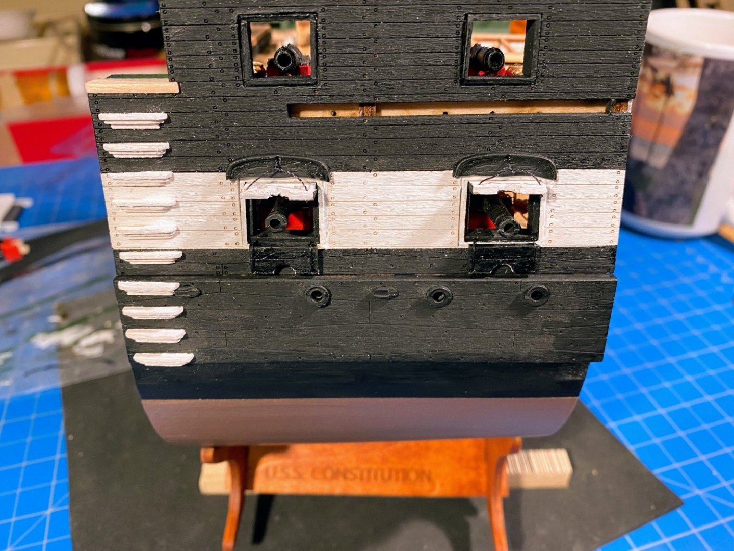
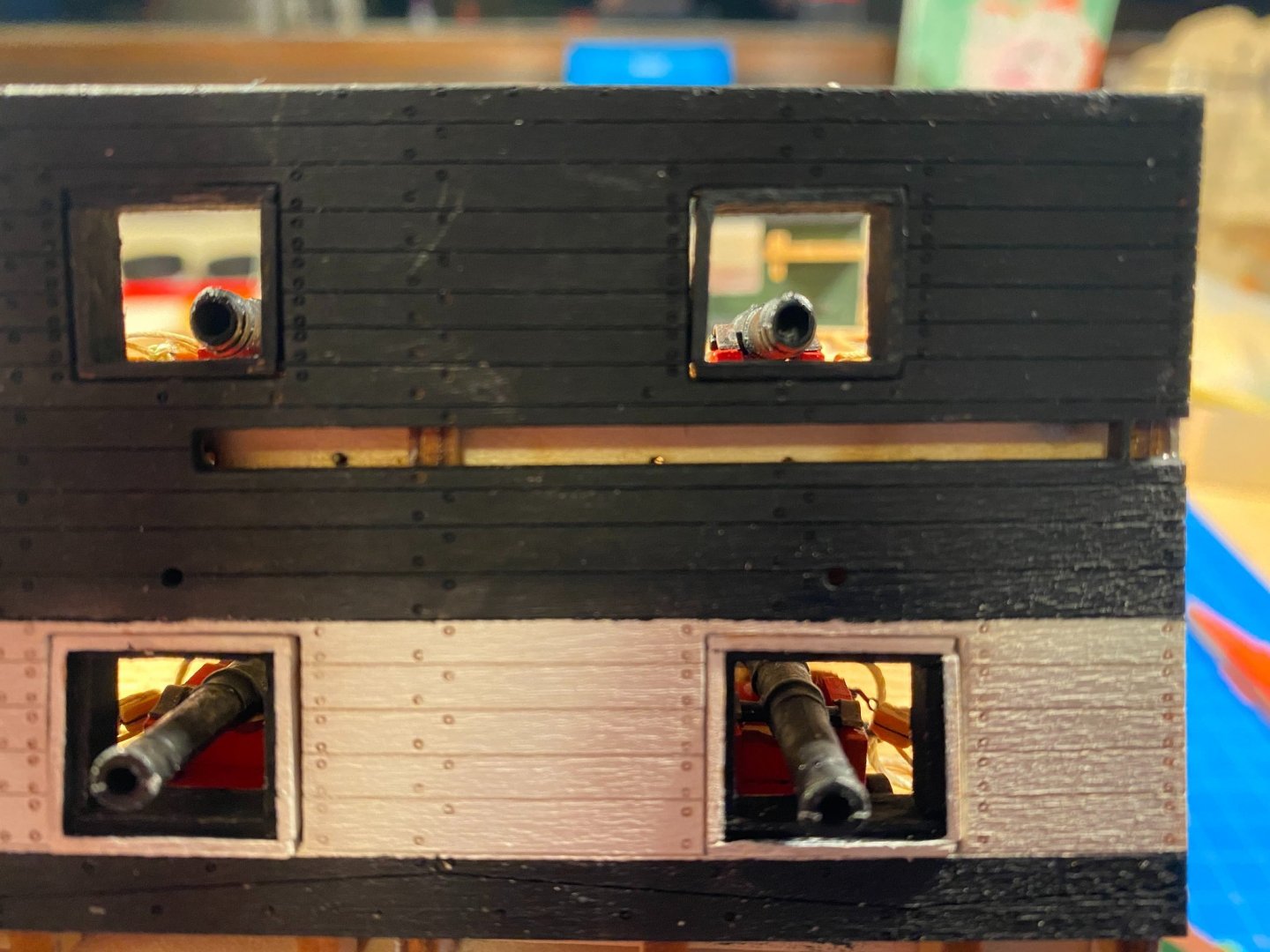
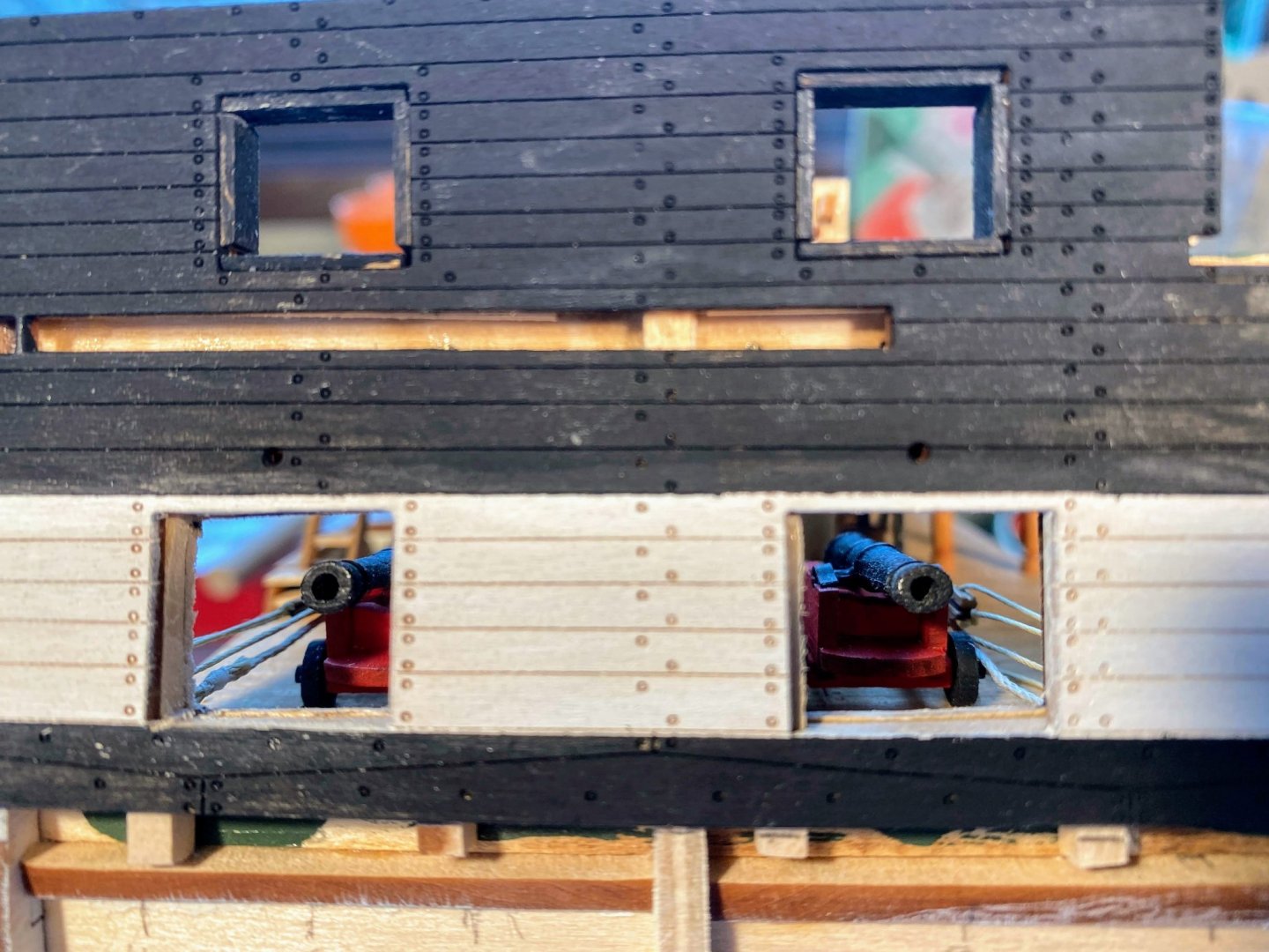
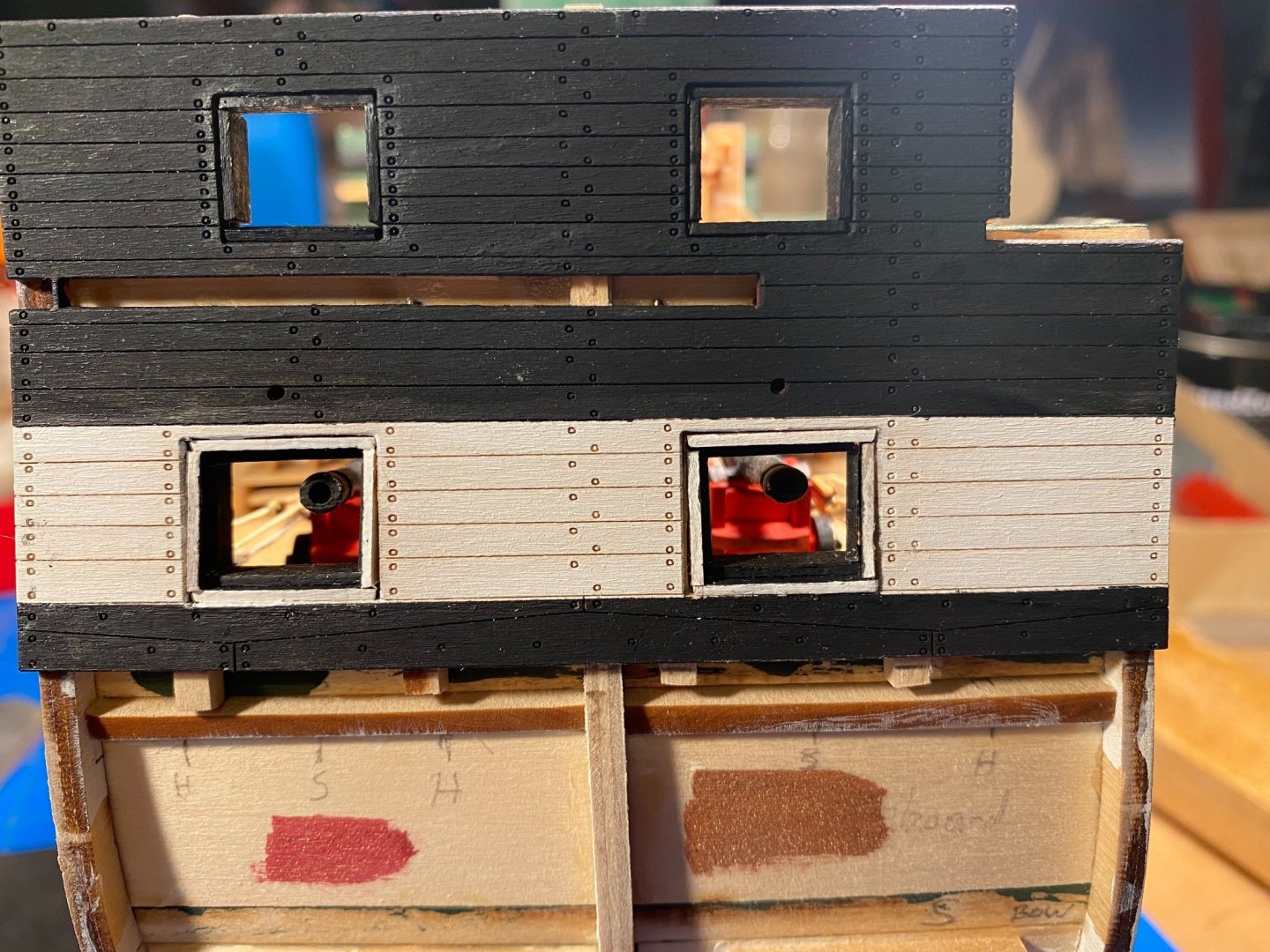
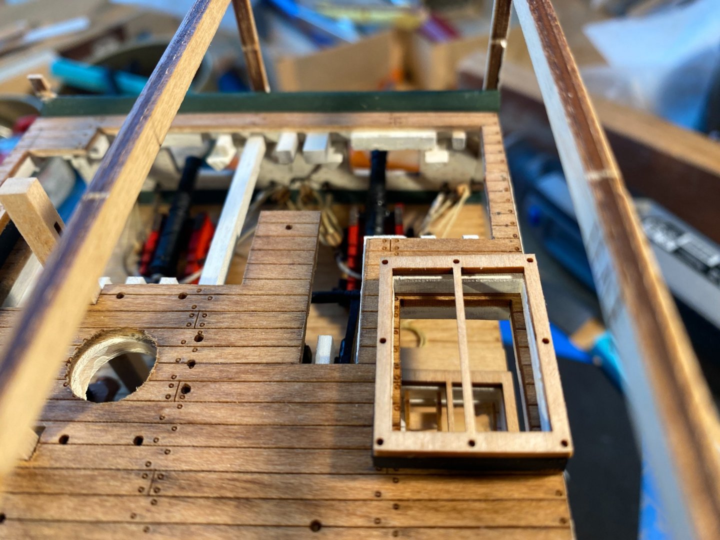
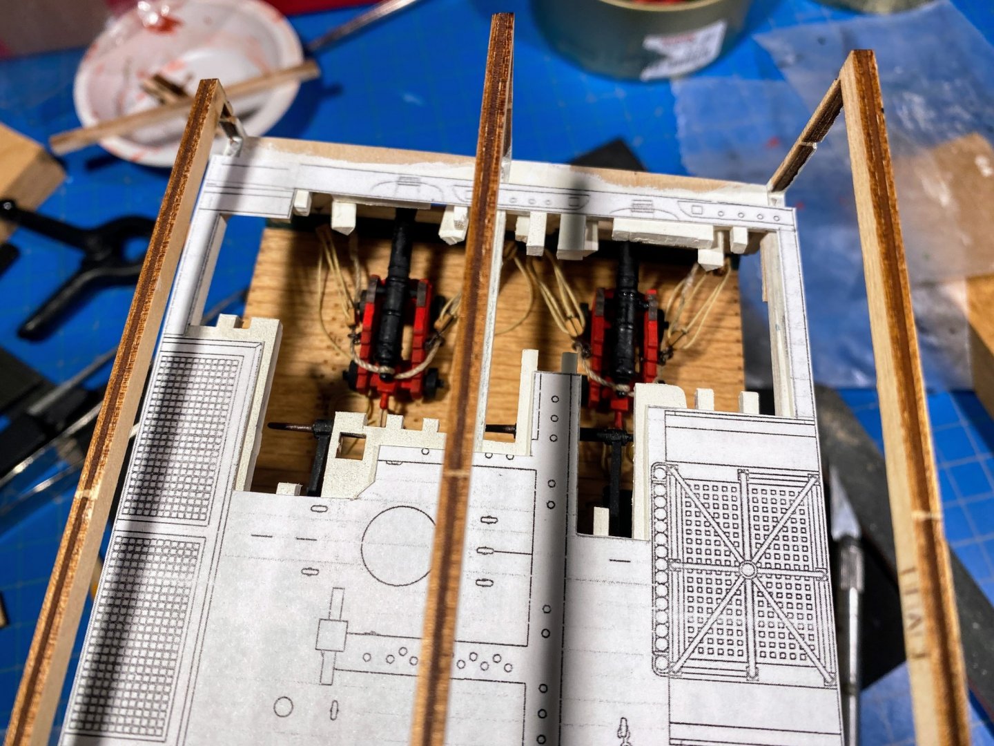
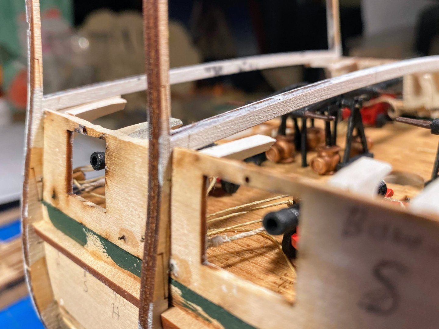
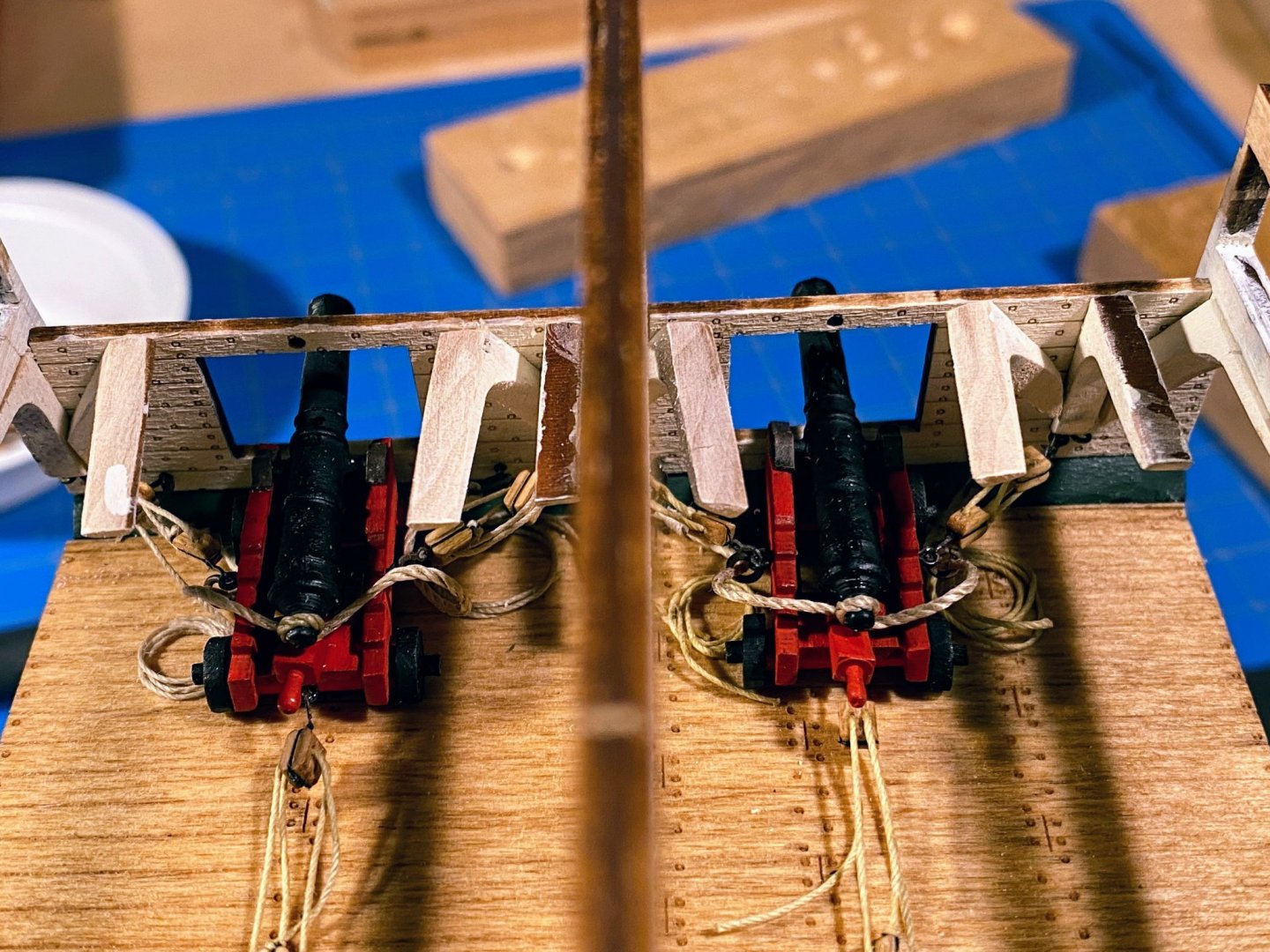
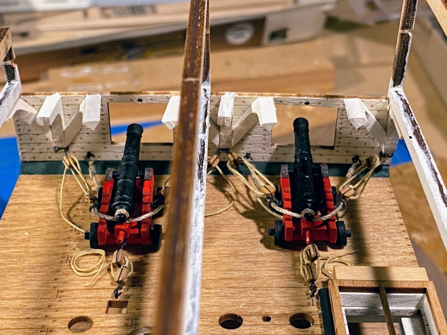
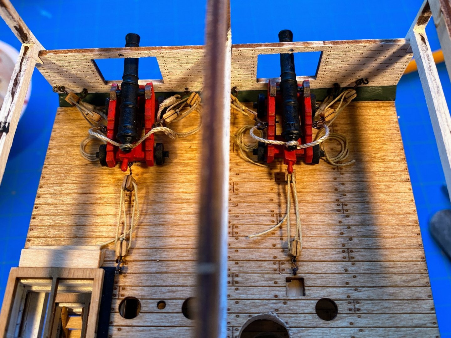
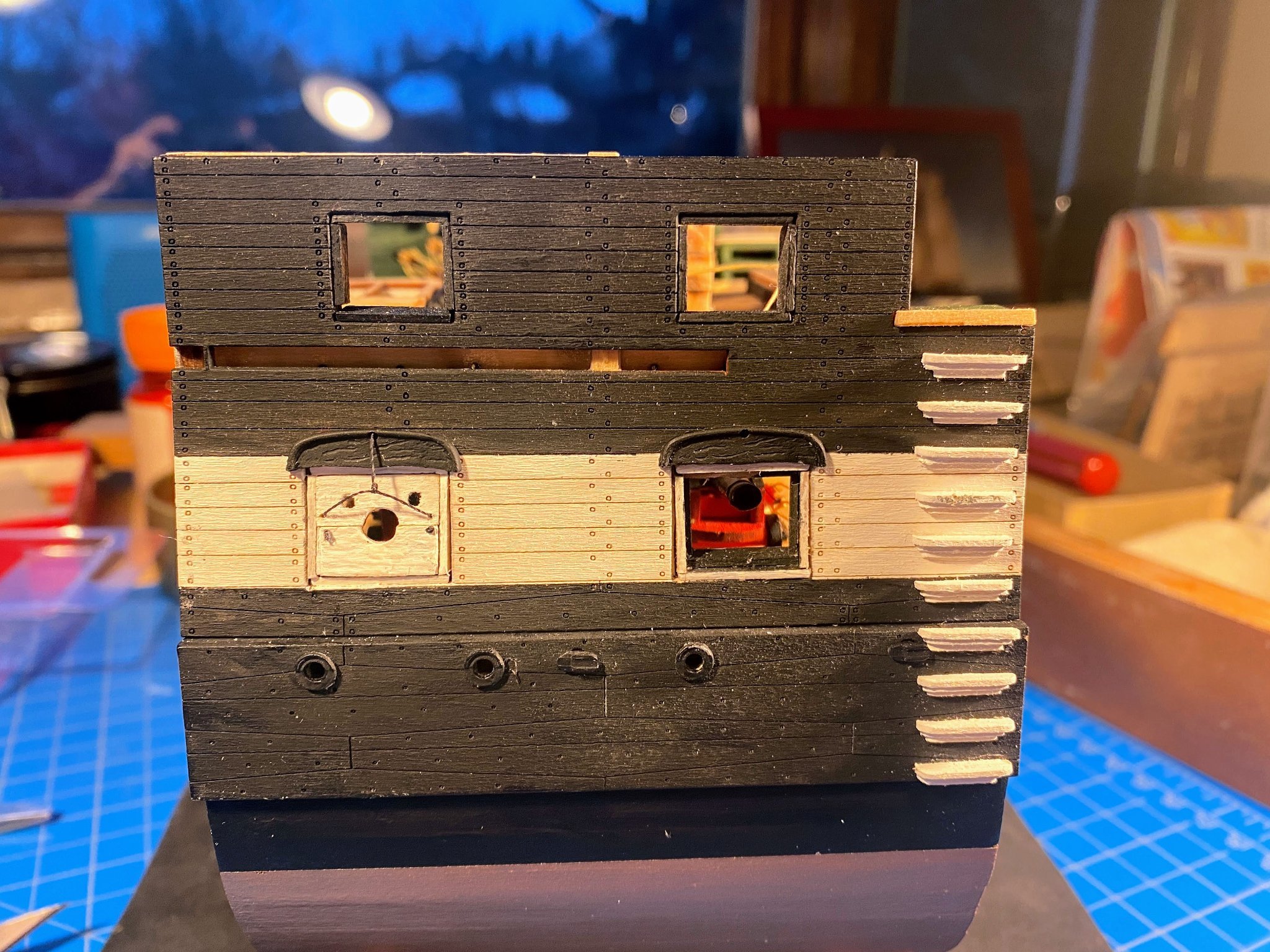
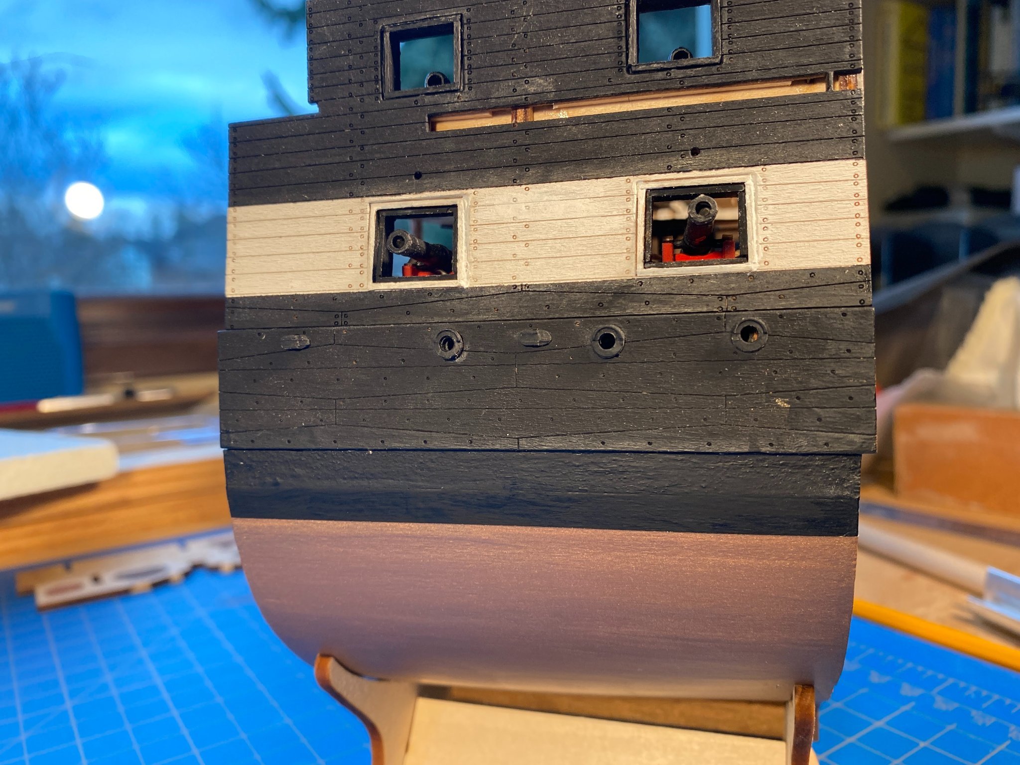
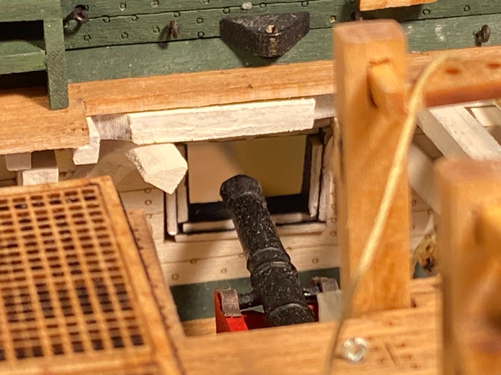
I actually had a good start on the gun port lids (or hatches) when I wrote that last post, and the guest room wasn’t needed until a day later than I had planned on, so this post comes along sooner than I expected. I decided to start with the starboard side ports. Recall my major kit-bashing . . . cutting a hole in the spar deck on that side to open up visibility to the long guns and other details below, and installing those cannons in recoil position with the result that their port lids could be displayed closed. Each pair of lids forms a hole through which the gun barrel can poke through. Each upper lid has an additional pair of holes, which I assume were there for ventilation. In the laser-cut upper lids, these additional holes are almost as large as the cannon barrel hole, which just doesn’t look right. Looking at pictures of the real ship in Boston and various models of the entire ship (including the one developed by MS), the vent holes should be much smaller. This bothered me enough that I cut out my own upper lids with much smaller vent holes. I drilled holes for two lids in 1/16” stock, then split the stock in half to separate the two. The gun barrel hole had to be 11/64” in diameter to match the lower lid, and drilling the hole proved problematic. Even when drilled by using a handful of successively larger bits, the wood split in two well before I could get the hole as large as 11/64”. I then used a pin vice to get the holes to about 1/16”, then used a conical shaped sander on my Dremel to finish the job. All of that took a while, but it worked. Once drilled, I painted the outsides of each lid white and the insides black, consistent with what I saw in photos of the real ship and other models (but not the photos in the instructions which show both sides white). I had made the upper lids intentionally about a millimeter large in both dimensions, just to be safe, so some trimming and sanding was necessary to get them to size, particularly in the case of the port on the right in the pictures. Both lids have rigging to assist in opening and closing them. The instructions would have you make the rigging out of 34 gauge (.006”), but wire that thin is not supplied in the kit. The photos in the instructions (especially the one on page 49) use wire that looks thicker, and which to my eye looks too thick and stiff. I assume this was rope that was belayed on a cleat and or maybe wound around a small winch; in either case it had to be something flexible. I used some of the .008” black rigging line which came with the kit, which looked much better to me. I dipped the ends of it in diluted white glue to make it stiff enough to pass it through the hole in the eyebrow and the tiny holes in the corners of the lids. On the lower lid I knotted a short piece of rigging line, tied a knot in it, ran the line through the hole, soaked it with more diluted white glue, and cut the ends of the knot (on the outside) and the bare line (on the inside). Starboard lids completed, the guests are arriving, and I’ll get to the port side later next week.
.thumb.jpg.1844fe71c0b17022d9d900eab49f2f8e.jpg)

.thumb.jpg.5494b01c85a7f1799e8ad42839931d4b.jpg)


- 163 replies
-
- 5
-
-
- Model Shipways
- Constitution
- (and 2 more)
-
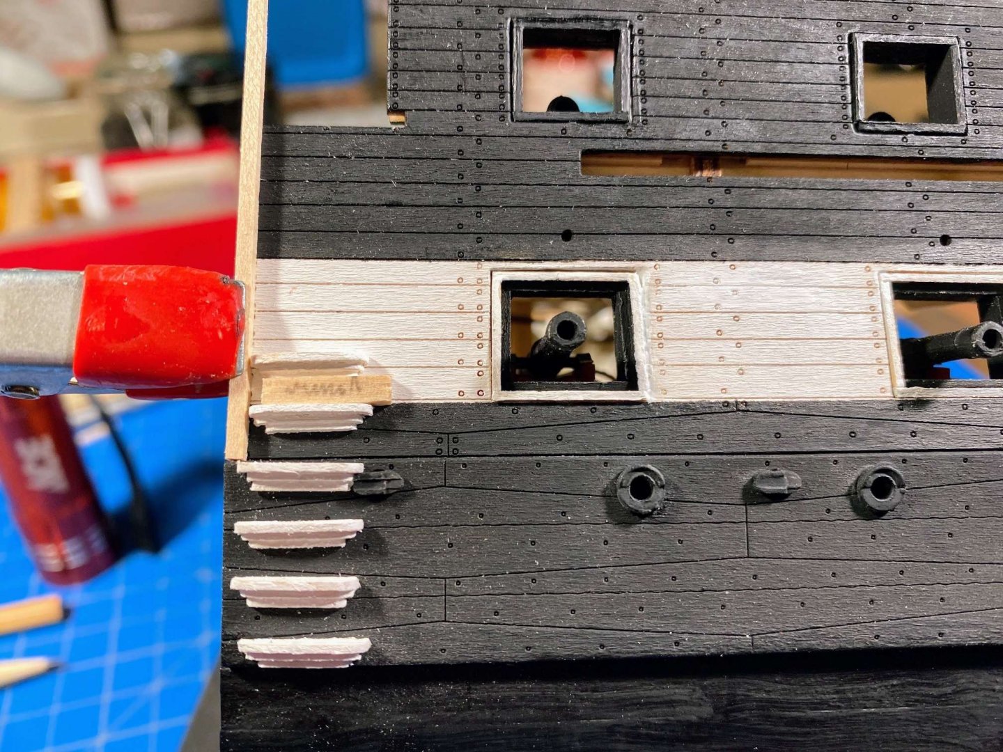
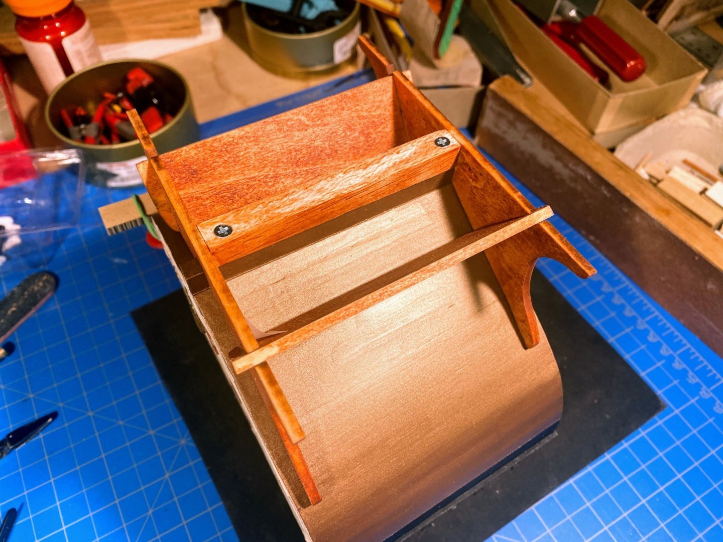
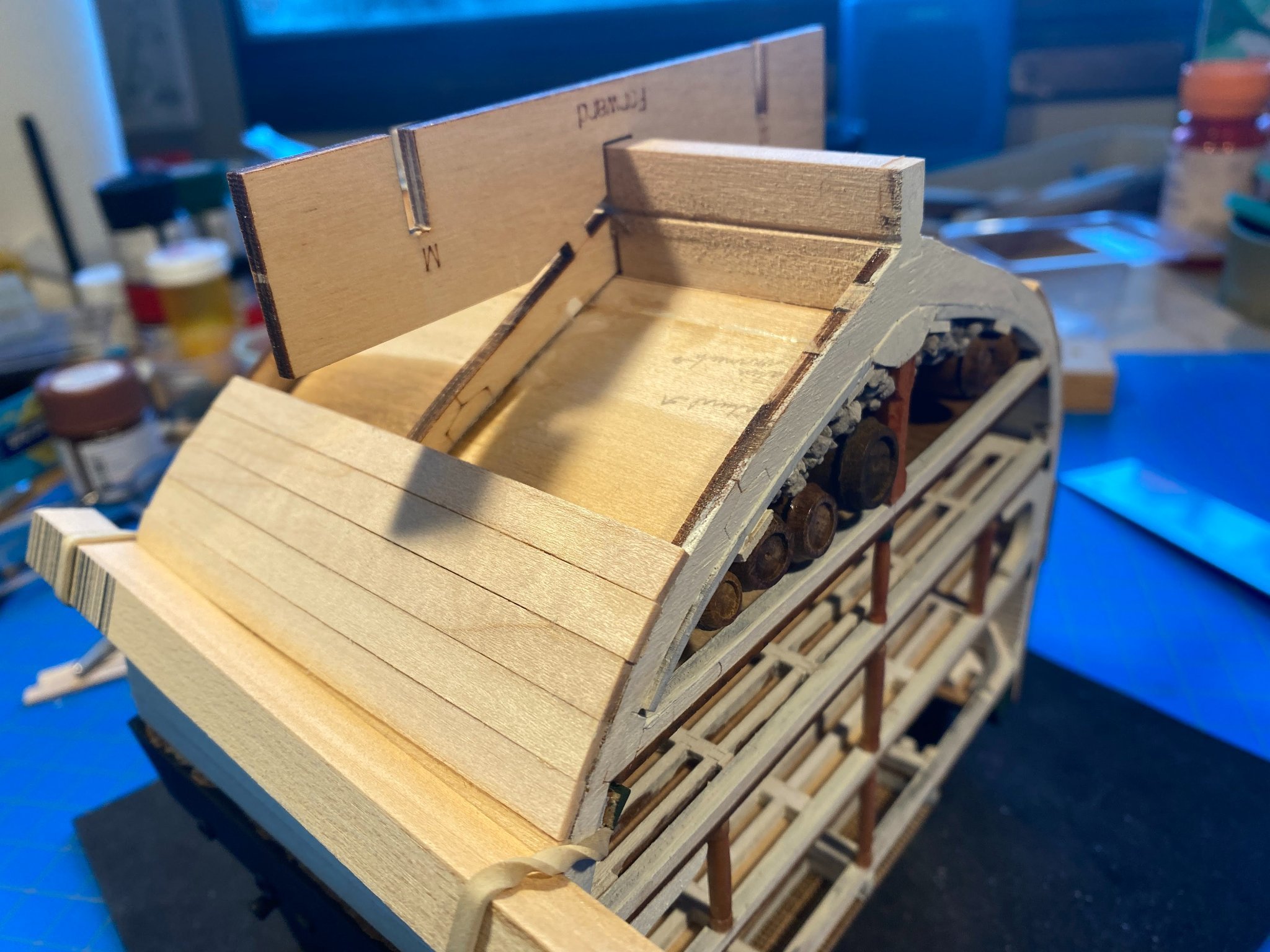
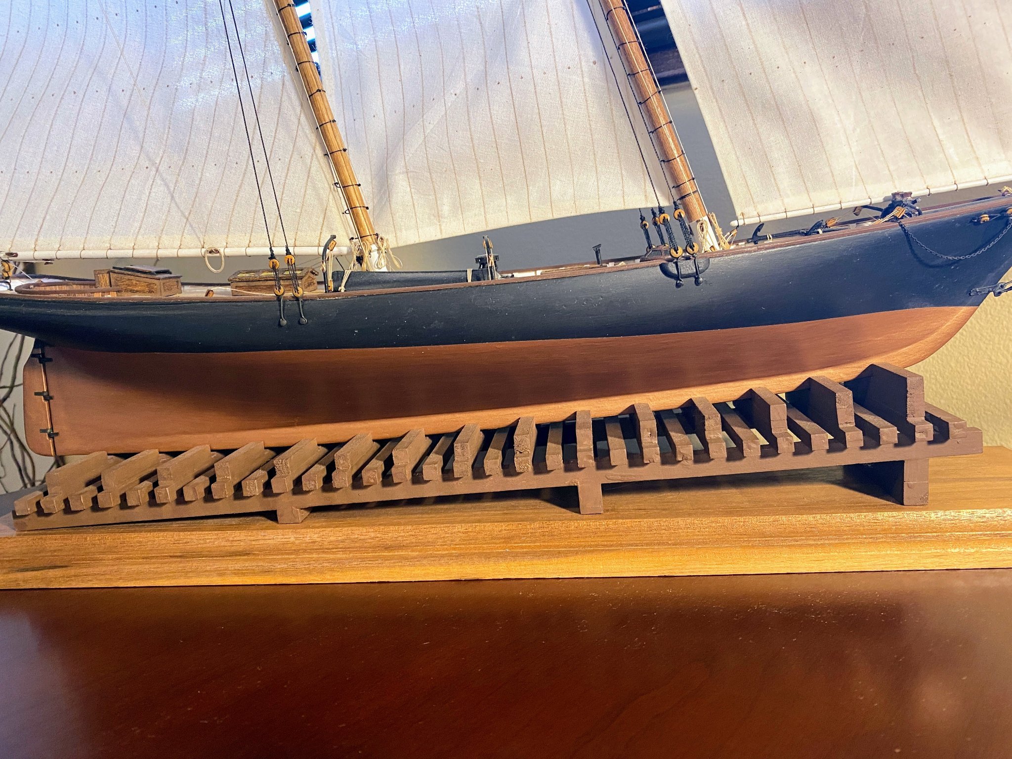
With the hull painted it was time to turn it back right side up. I feel like I’m coming around the final bend and headed for the finish line . . . as to the hull, that is. Major projects between here and there appear to be the boarding (or sea) steps, the gun ports (including “eyebrows”), the hammock railing & cap rail, and the channels & deadeyes. For whatever reason, I chose the steps first. Ten step assemblies on each side means cutting various lengths of 1/32” thick strips (incorrectly said to be 1/64” in the instructions) with widths of 3/32”, 1/16” and 1/32”, for a total of 60 tiny pieces. Each piece needs to be sanded round at the outside corners, and then a piece of each dimension needs to be glued together to create a single step assembly. The instructions suggest building a jig for cutting the pieces, but years ago I bought something called “The Chopper”, and it has proved to be one of the most valuable of my collection of tools. Only complaint I have is that it does not have a built- in ruler, but that’s really not much of an issue. Once cut, assembled and painted, I glued 10 on each side, 1/16” back from the forward rib. The instructions say the four steps glued to the wales need to be flush with that rib, to make room for the forward scupper. I found enough room while maintaining a consistent 1/16” back, and I thought consistency looked better if it was possible, as it was. The instructions also say to space the steps apart with a piece of 3/32” strip, but fortunately I measured the space to be filled and did the arithmetic, and 3/32” was not wide enough. I laid the steps out with 1/8“, and that was a little too big. We all know that wood strips are not milled as precisely as we’d like, so I found a “narrow” 1/8“ piece and used that. The space between the top built step and the deck level step (yet to be glued in) is a little too large, but not enough so to be noticeable. It then occurred to me that I ought to assemble, stain and attach the stand while I could still turn the hull upside down. The smallest wood screws I could find were bigger than the ⅛” thick frame pieces, so I installed a cross beam along the keel to put a couple of screws in. For stain I used Verathane’s “Traditional Pecan”. It’s a bit bright for my taste, but not as much as the photos would lead you to believe. I think I’m OK with the color, but I’m having some doubts about the stand as a whole, since it obscures so much of the hull. A decision for another day, but I’m thinking about a couple to conventional pedestals mounted on a wood base. Finally I glued the “eyebrows” above the gun deck ports. Next step is the port lids, which is likely to be delayed a bit as the shipyard is becoming a guest room for the holidays. Merry Christmas everyone.


- 163 replies
-
- 3
-
-
- Model Shipways
- Constitution
- (and 2 more)
-
Clearly this was going to be, and proved to be, the easiest hull planking I have ever done. Also a big milestone in separating the hull from the base it has been part of since the start of this build about nine months ago. Following the instructions I planked from the wales down, about 2/3rds of the way, before cutting off the base. The kit comes with plenty of 1/16” x 3/16” stock for planking, but I have a bunch of 1/16” by 1/14” lying around, and I decided to use that instead. Fewer planks to cut and glue on. And I don’t think I ended up with any more plank lines than I would have with the narrower planks. But first I was concerned about damaging the long guns that stick out from the hull on the port side, so I took a piece of ½” by ½” scrap and rubber banded it to the hull below the guns, to give the hull something to rest on other than those cannons. I have an Xacto miter saw and box, and long ago replaced the standard saw blade with one with much finer teeth that I found online -- makes all the difference in the world for things like sawing the base off the hull. Free of the base, I glued three planks coming up from the keel, and gradually closed the gap between those planks and the ones coming down from above. As expected the closing planks had to be tapered to fit. The instructions say to cut them from a 1/16” x 7/16” strip, which wasn’t listed in the parts list and wasn’t included in the kit. I cut them from more commonly found 1/16” x 1/2” stock (also not supplied) I already had in the lumber yard. In the third picture below they are the fourth planks up from the keel. You'll also see that months ago I tested some stain on the bottom side of the orlop floor. I then painted everything from the wales to the keel with some Model Shipways primer, did some filling and sanding, and then applied a couple of coats of Tamiya flat black. No pictures of any of that painting. What followed was carrying out what may be a controversial decision I’ve been mulling over for some time. Personally, and no offence to the many on these forums who have built beautiful models doing otherwise, I have never found copper plating to look that great on ship models. It also looks like a lot of very tedious work. The kit comes with a roll of 1/4” copper tape, but I decided to use copper paint instead. There is an intersting discussion on one of these forums on this topic, and there are those whose frame of mind on this is similar to mine and those who feel otherwise. A few years ago I built Model Shipways Yacht America, which I painted copper below the waterline and I have been pleased with how it turned out, so I decided to do the same with my Connie. For the America build,I found it difficult to find copper paint I liked. I ended up using Tamiya’s Dark Copper, and darkened it further as described below. For this build, I bought some of that paint, and a bottle of what Model Shipways calls Copper. I applied a small amount of each to the backside of one of the sidewalls to see how they would look. The MS Copper doesn’t look like any copper I’ve ever seen. It might more appropriately be labeled Bazooka as it reminds me of the bubble gum I occasionally chewed as a child. The Tamiya Dark Copper does look like copper, but I don’t see anything dark about it. To me it looks about as dark as a shiny new penny. With the America, I mixed something darker with the paint to take away some of the shine; I don’t remember exactly what color I added. This time I found some Tamiya Dark Grey in the paint locker and carefully added that, several drops at a time, to the Dark Copper to get something like a darker older penny. The first coat revealed a greater need than I expected to do more filling and sanding (it looks brighter in the picture than in real life). The look I’m striving for is the elimination of any planking lines, but not trying for silky smooth since the Connie’s hull wasn’t made of fiberglass. Maybe that’s just creative rationalization, as I easily get bored with filling and sanding. Bottom line though is the most important judge and jury watching this build (that being me) is happy with the result.


- 163 replies
-
- 5
-

-
-
- Model Shipways
- Constitution
- (and 2 more)
-
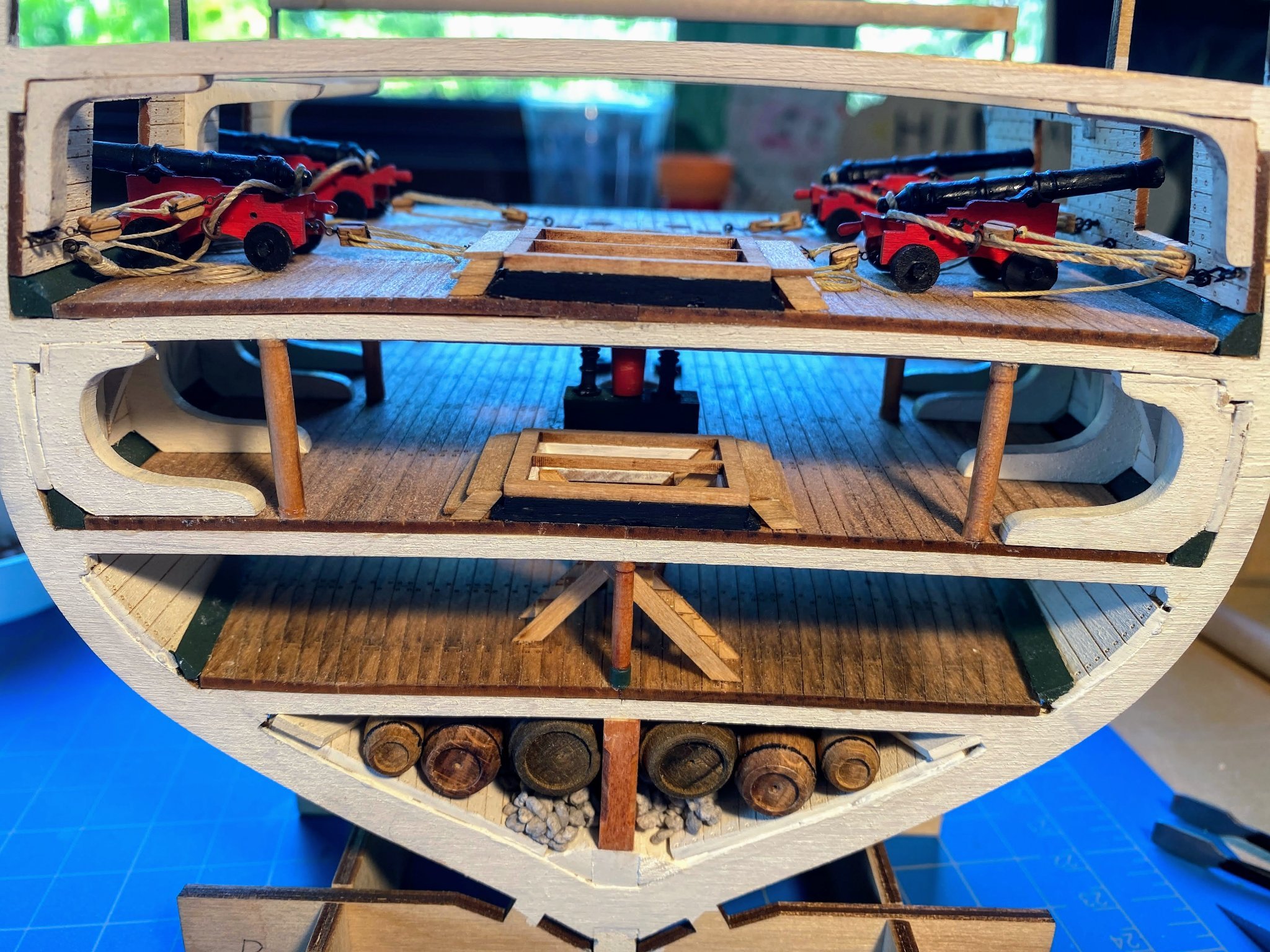
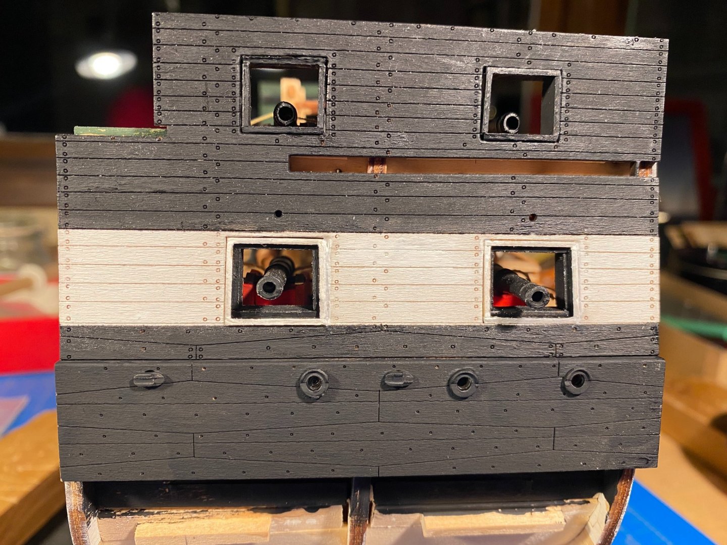
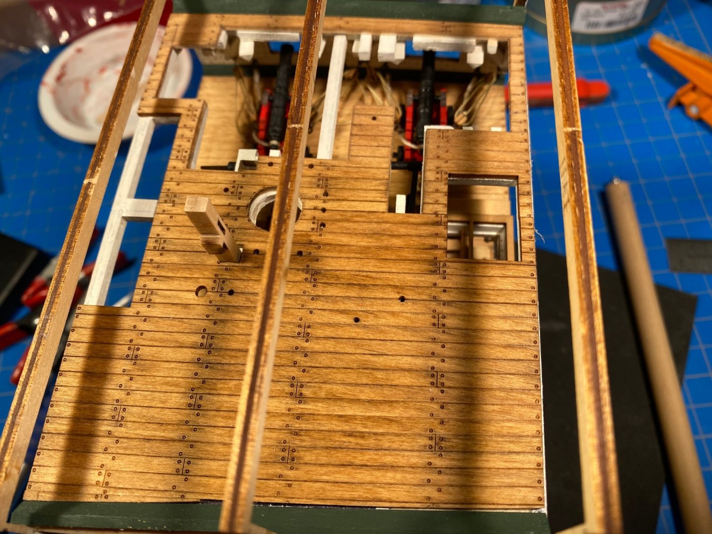
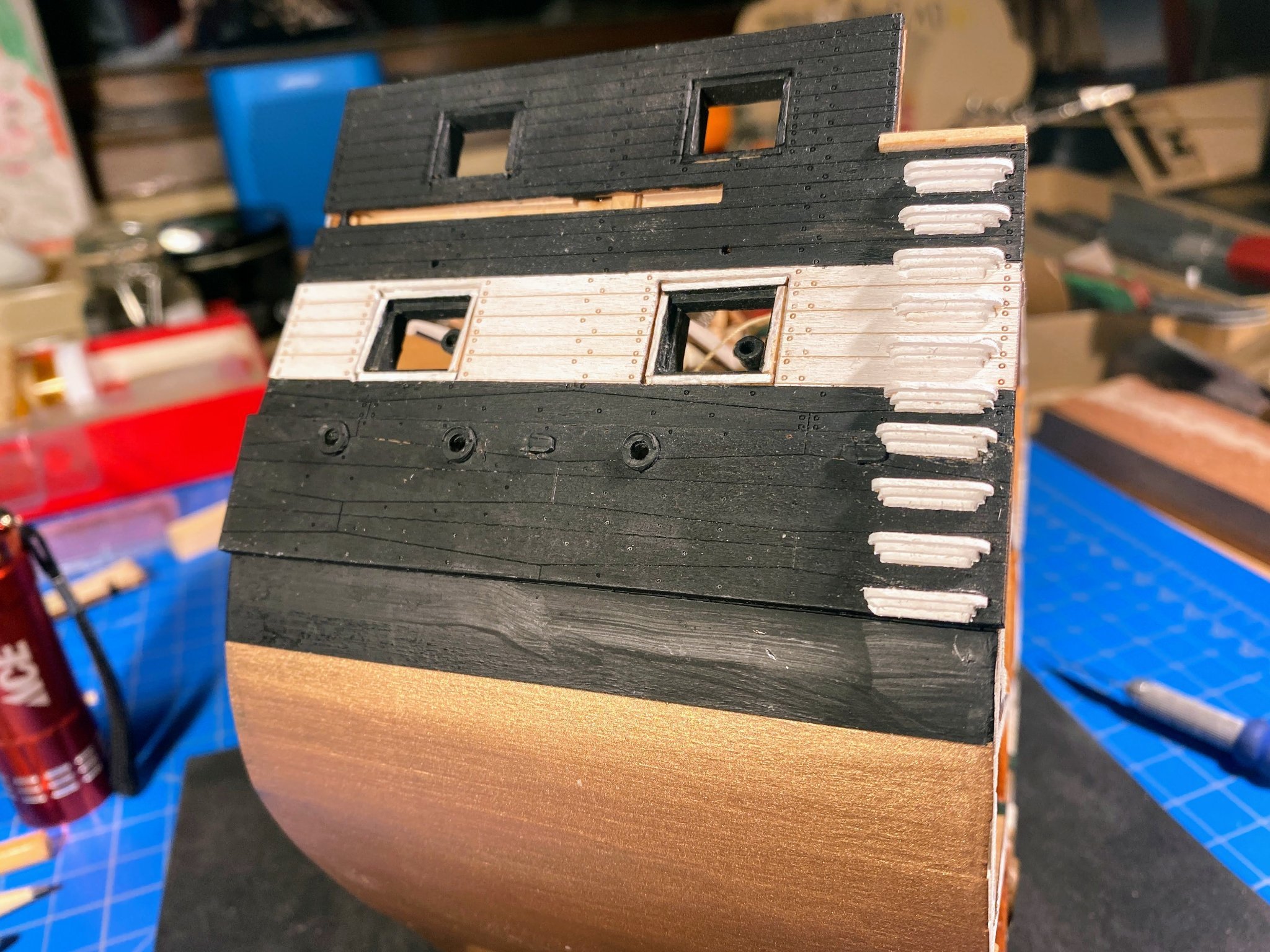
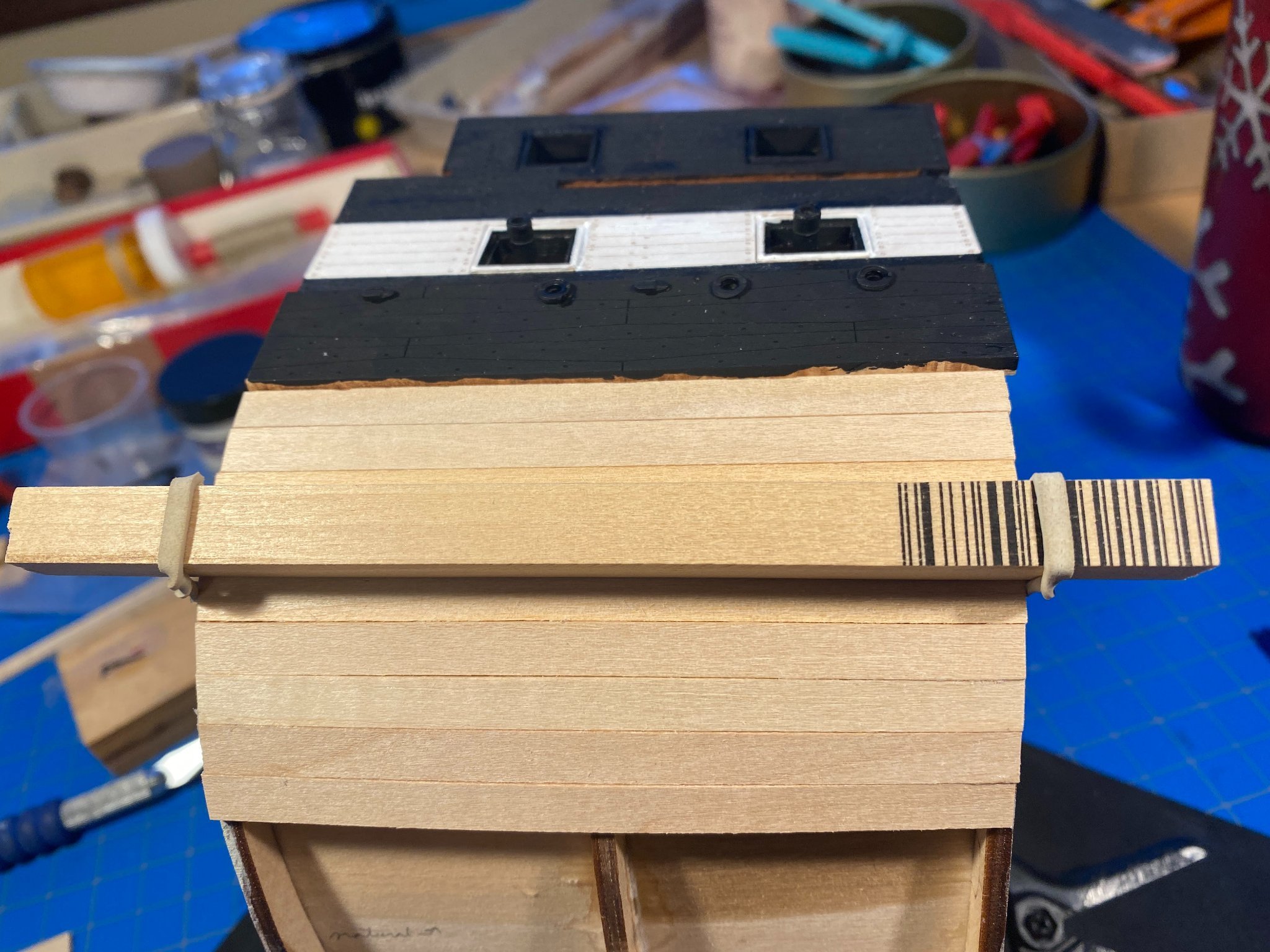
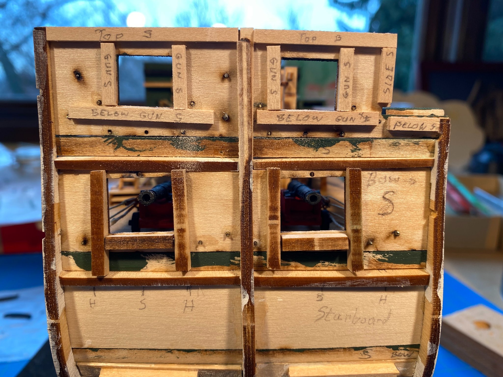
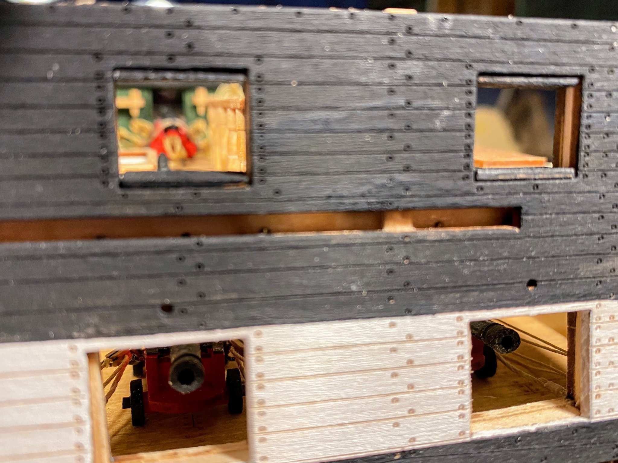
The last couple of weeks in the shipyard got increasingly challenging, putting together the gun and spar deck outer walls and framing the gun ports. Things started easily enough . . . a laser cut wall for each side, spanning two decks. As usual the laser cutting, and the scribed detail on the outer sides, are very good. Both were painted black, with the white gun stripe. It’s beginning to look like a war ship! At the spar deck level the wall is a consistent 3/16” thick, inner and outer walls being 1/16” each, and what the instructions call “braces”, also 1/16” thick, between the two walls. Those braces are cut from 1/16” x 1/8” stock, and they frame the gun ports and provide gluing surfaces between the walls (in addition to the ribs). I cut all 20 pieces at the same time, labeling them as you’ll see in the next photo of the port side. At the gun deck level, the inner and outer walls spread farther apart, and the braces at that level are laser cut. They are helpfully scribed B, M, M and S, for bow, middle, middle and stern. As cut, they are actually maybe 1/8“ too long, and in cutting them shorter I overdid it a bit, but no matter. About a month ago (first picture below) installing the inner wall on the starboard side I confronted the fact that the middle rib on that side extends outward out of line with the forward and aft ribs. I don’t know whether the laser cutting of that middle rib is at fault, or whether I was sloppy in putting the ribs and the base together last spring, but it’s an issue that gets worse the further away you are from the keel. To deal with it when installing the inner wall, I glued a 1/32” shim to the inside of the inner wall. In the second picture below that problem is not obvious, but you can see that I had started trying to thin that plywood rib by sanding it, which I quickly realized would be inadequate. What I eventually did was to cut the rib off at the level of the spar deck, and then glue another 1/32” shim to the one already there, so that this replacement rib is the requisite 1/16” thick. Below the spar deck I thinned the rib with a lot of grinding with my cordless Dremel tool, followed by a lot of sanding, to get that rib to conform with the other two. Unfortunately I didn’t take any pictures of that process. Nor did I get pictures of what follows. I think I was too focused on what proved to be a difficult task. I tackled the port side first. The gun ports are framed with laser cut 1/16” pieces. The instructions have you glue the outer walls to the ribs and braces, carefully aligning the gun ports as best you can. They then have you assemble the gun port framing, building little boxes that you then slide into the ports. I built the port side frame boxes as instructed, then tried to use them to help align the sides when gluing the outer wall on. To make a long story short, at the gun deck level the outer wall ports simply did not align very well at all with the inner wall ports. More on that later, but first a few words about the frames. At the spar deck level, they are simple four sided boxes 3/16” deep. Oddly they are not even mentioned in the instructions, but they are identified in a caption to one of the photos in the instructions. At the gun deck level, they are slightly more than 3/16” deep at the top, and deeper than that at the bottom. So the top and bottom pieces vary slightly in width (something that is easy to overlook), and the side pieces are somewhat trapezoid in shape. These frame boxes also differ from the ones at the spar deck level in that another frame box fits inside them, flush on the inside edge, and inset 1/16” from the outside edge. I think the reason for this double framing is to provide for a ledge for the gun port lids to rest against when they are closed. I took the approach of building the outer box first, then gluing the sides of the inner box to the inside of the outer box. Sliding and gluing the port side spar deck frames into their respective ports went reasonably well, but I was still left with gaps between the frame and the wall along the sides, as can be seen in the picture below. Most of the gaps I filled with paint, but I pulled out the offending frame shown below and rebuilt it. At the gun deck level, the frames simply wouldn’t fit at all, and I had to do a lot of shaving of the inner wall with my Xacto knife, followed by some sanding, to get them to fit. Needless to say that was nerve wracking, as I didn’t want to do any damage to the long guns and their rigging. And of course my fat fingers and thumbs pretty well blocked any view of what I was doing. The end result, after doing some cosmetic work, wasn't bad. The second picture is obviously after gluing the wales in place. On the starboard side I decided to take a different approach. Rather than build frame boxes, I would glue the frames piece by piece into their respective ports. That worked OK on the spar deck level, although I can see I lft some gaps. On the gun deck level, as on the port side the gun deck outer wall ports did not align well at all with the inner ports, and a great deal of shaving and sanding was needed so that the frame pieces could be glued in. The misalignment was mostly longitudinal; that is, the inner wall port was a few millimeters aft of the outer wall port, and the forward side of those ports had to be cut back. What I didn’t think about was the fact that the aft side of those ports was of course misaligned as well, meaning that the outer wall obscured the fact that the edge of the inner wall was a few millimeters aft, leaving an uneven surface to glue the frame piece to. On this starboard side I need to do some cosmetic work, but I’m not sure exactly what to do. Actually I do know what to do . . . take a break from working on the ports and move on to planking the hull. I’ll ome back to the ports when it’s time to put in the port lids and when I’m fresher and and maybe have a little more positive attitude about the work I'm doing.


- 163 replies
-
- 5
-
-
- Model Shipways
- Constitution
- (and 2 more)
-
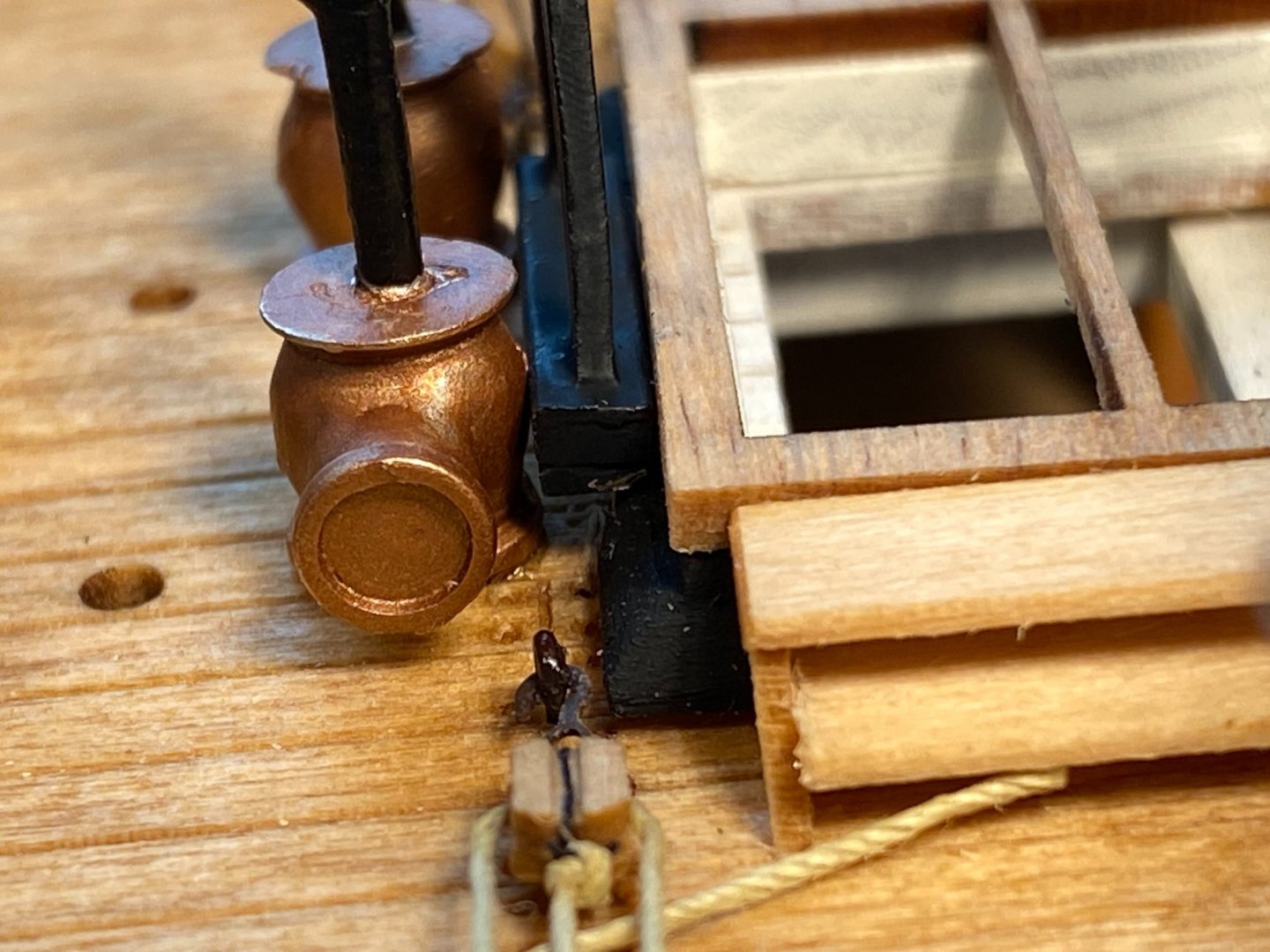
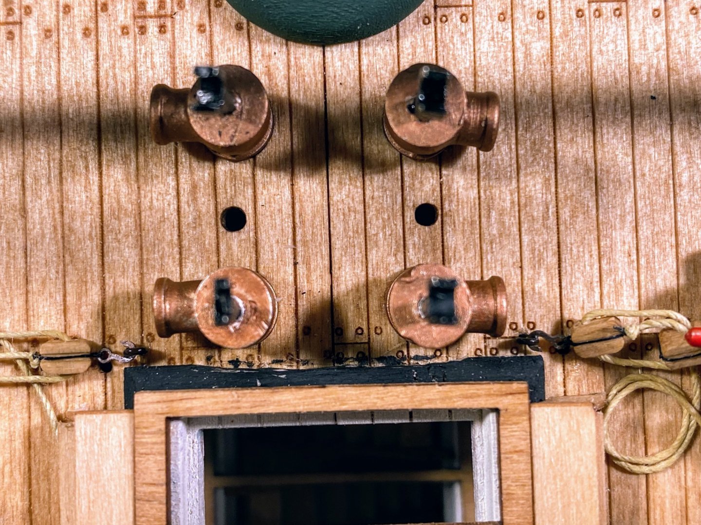
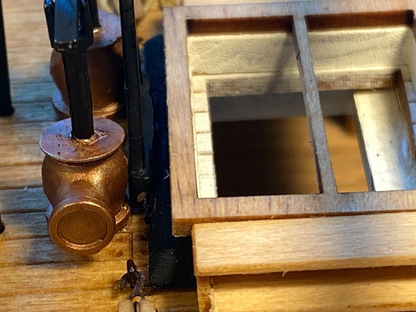
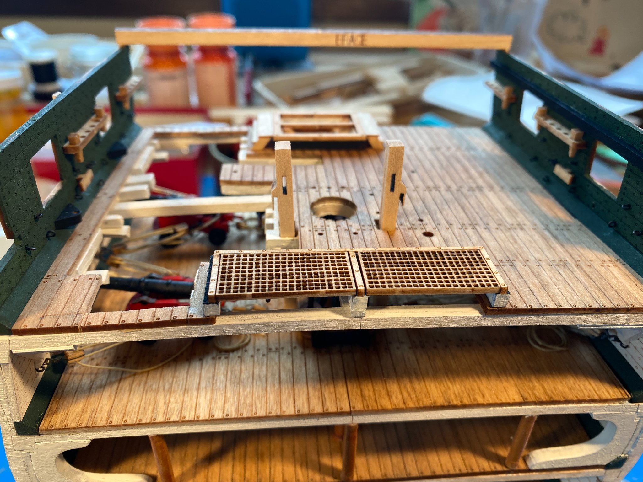
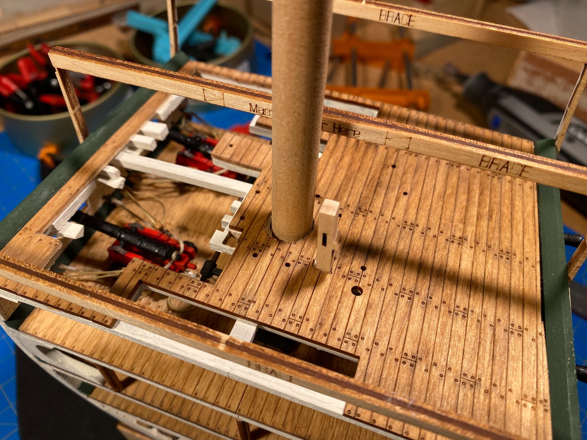
I redid the coils on the previously rigged carronade and completed all but one of the tackles and coils on the one I hadn’t done previously. A few words about rope coils . . . like real rope, rigging thread has a natural twist to it which can be taken advantage of. And like real rope, if you give the thread a half twist (after figuring out which way to twist it) as you make each loop, it makes a pretty neat coil. I’m a big fan of diluted white school glue for securing rigging -- it saturates the thread, looks like a mess while wet, but pretty much disappears as it dries, and holds everything in place nicely. After applying quite a bit of it, I’ll take a small piece of paper towel, torn or folded to a point, and use it to wick away larger drops of glue. Then I’ll use the butt end of a drill bit, or something similar to hold it down flat against the deck while it dries. In the pictures below you’ll see that I decided to hang one coil from a pin rack. I haven’t completed that job yet because I ordered some wooden belaying pins to replace the brass ones that come with the kit (why paint brass when you can just use wood?), and they haven’t arrived yet. Taking occasional breaks from tackle rigging, I finished up the rest of the deck furniture. The gangway boarding steps went together easily, except that I had to add a shim so that the risers would meet the waterway. The fife rail was next. I had to add a couple of shims where the rails meet the bits, so that the fit would be relatively tight. On close inspection the scratch-made stanchions could be straighter, and two of them were a tiny bit too short, so I had to hide a couple of shims on top of them under the rail, but neither problem is very obvious. There are holes in the deck for nine white eyebolts around the white mast surround As far as I can tell nothing will be attached to them, and I don't usually think of such things being painted white, but looking at the real ship (thanks to Google Maps), there they are, painted white and not used for anything. So they became part of my build. At least a couple of them need a tiny dab of touchup paint. There is a hole in the deck where an ammo scuttle needs to be installed, but I am still awaiting paint I ordered for it. Finally I added a couple of posts on the gun deck forward where I decided not to put in stairs. That more or less completes the decks and the ship's interior, so I get to move on to the outside of the hull. An exciting milestone!


- 163 replies
-
- 6
-
-
- Model Shipways
- Constitution
- (and 2 more)
-
Hi Dave, welcome from Spokane.
-
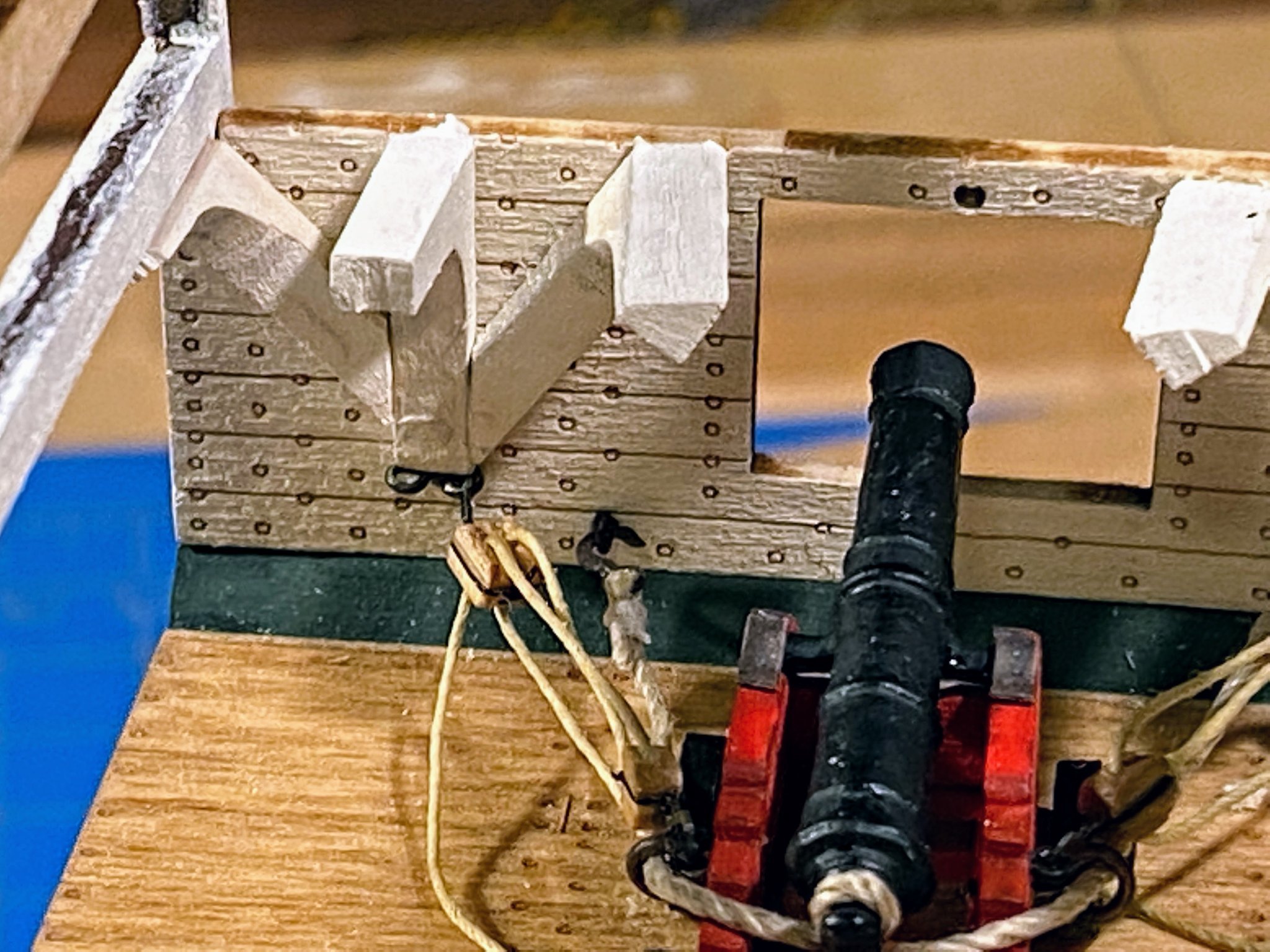
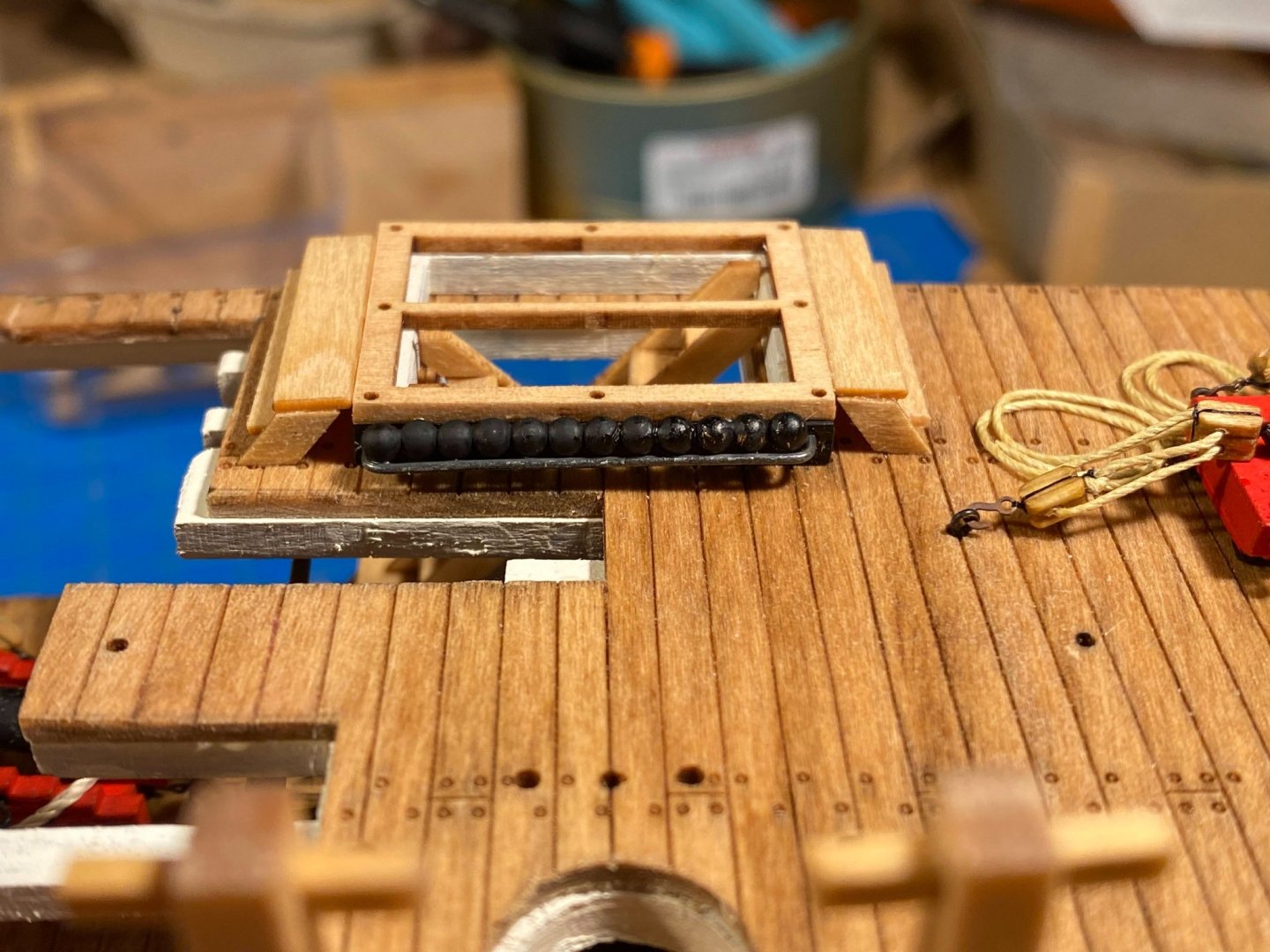
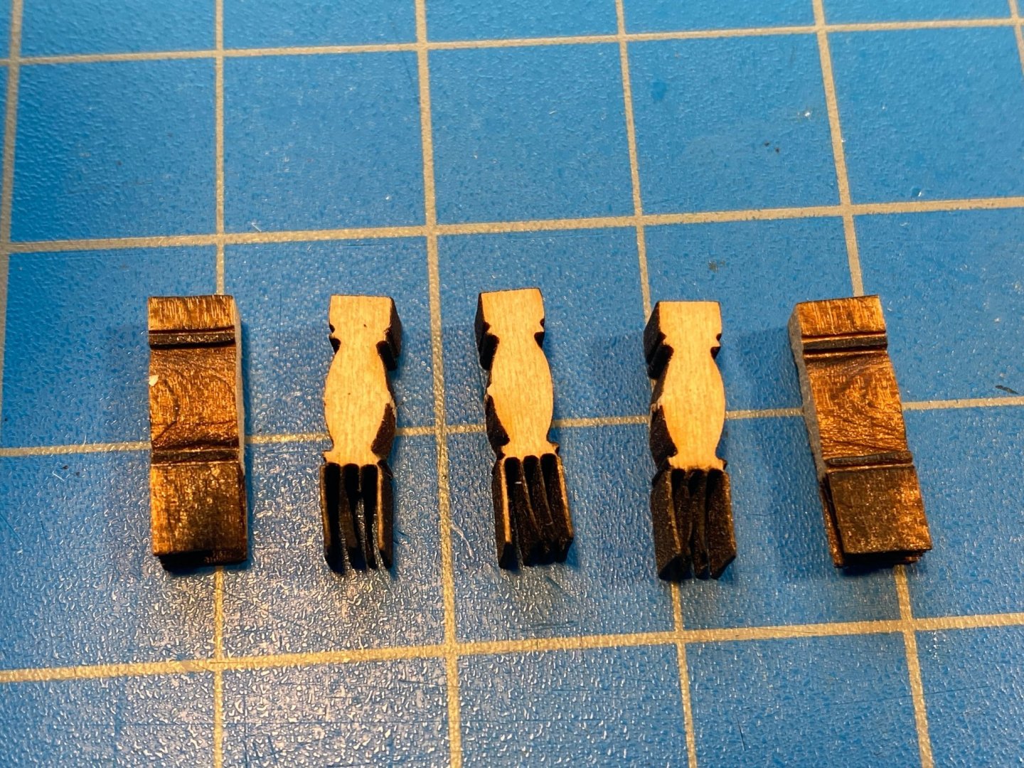
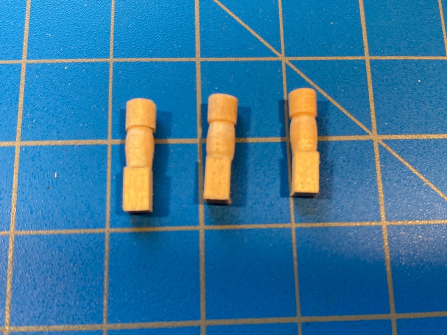
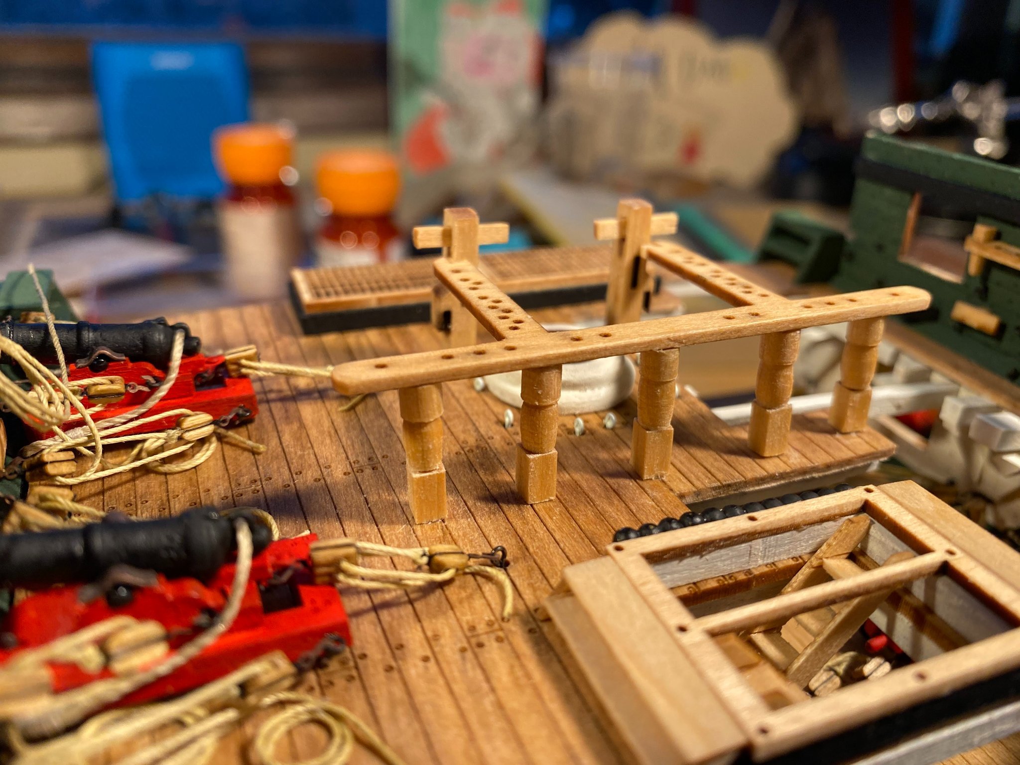
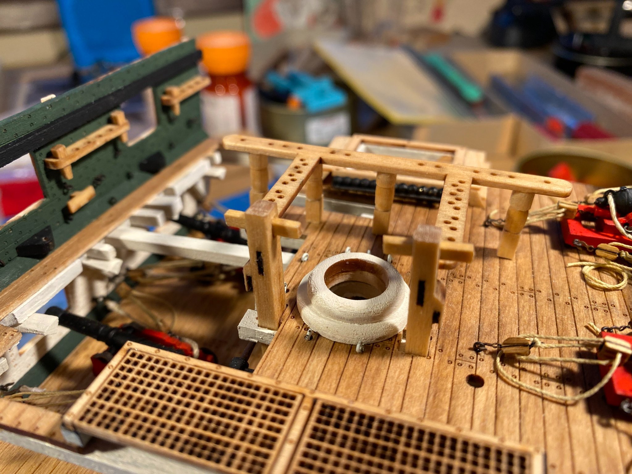
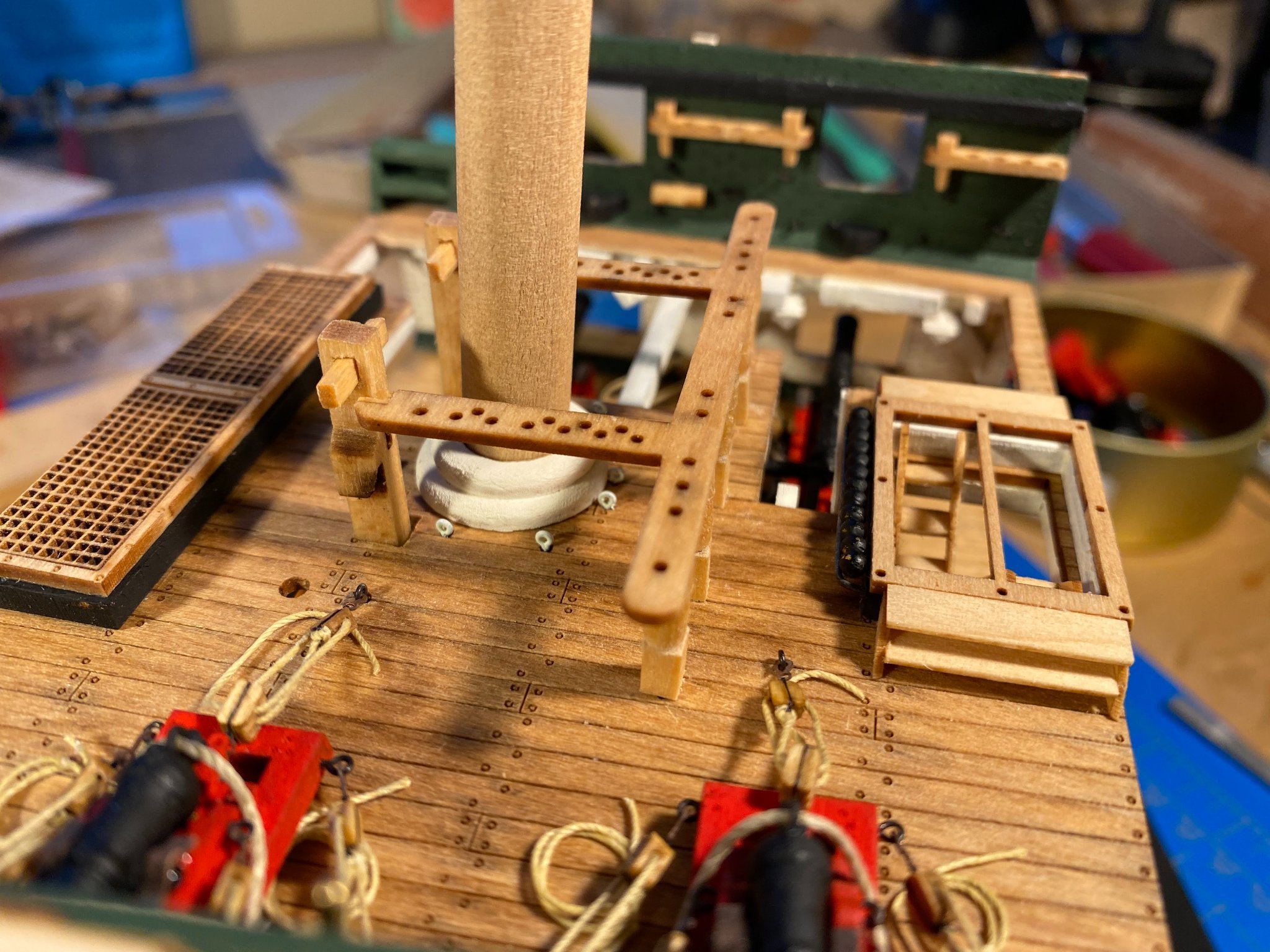
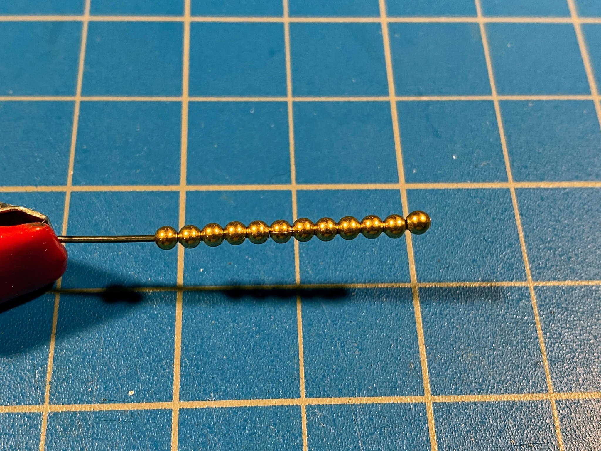
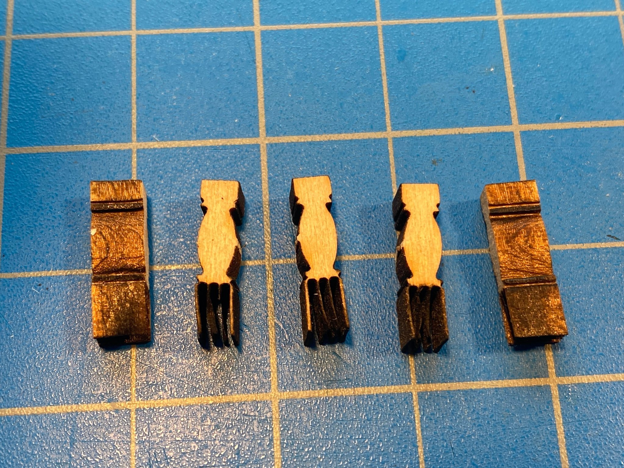
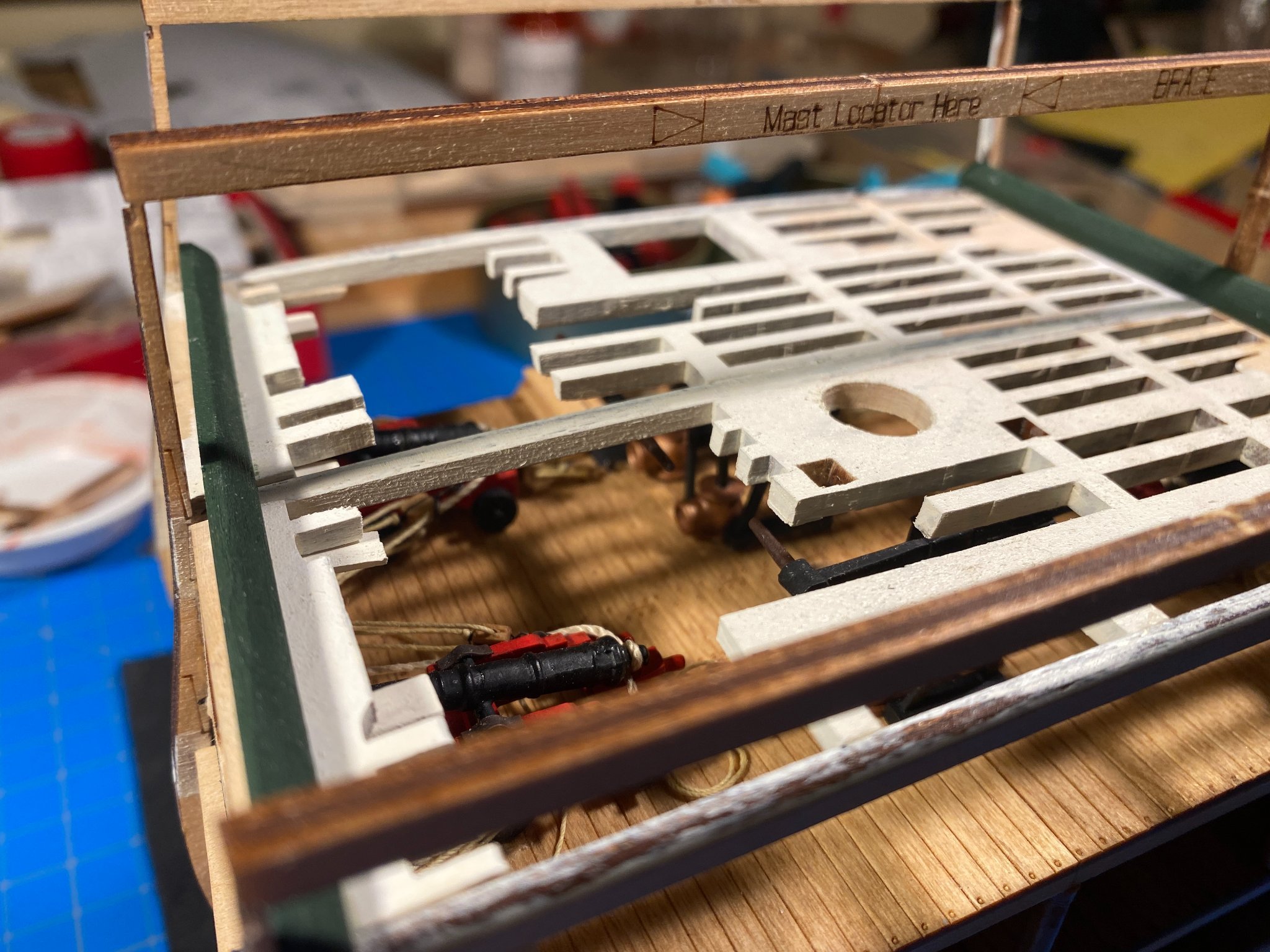
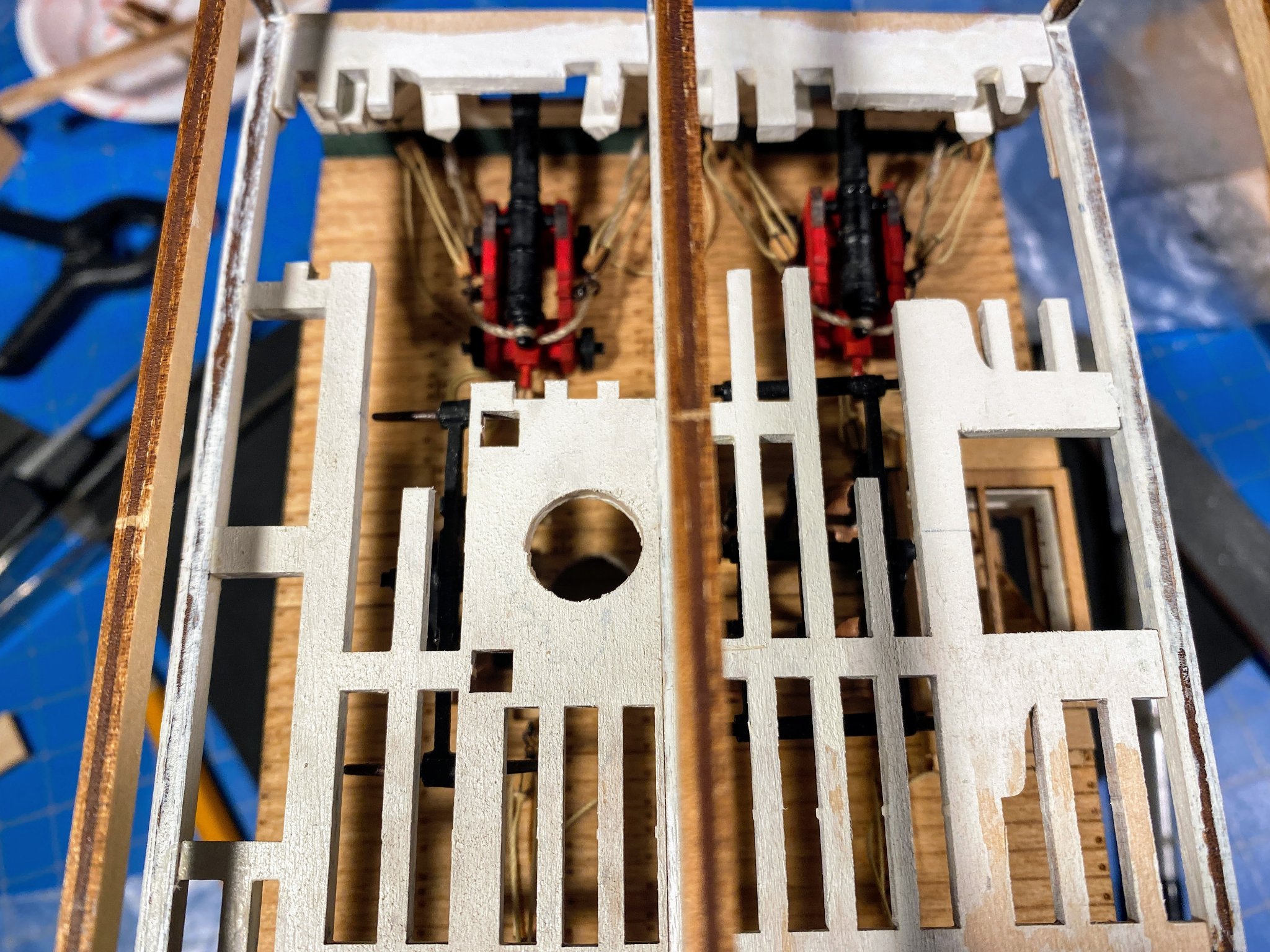
Meanwhile before tackling the second carronade (no pun intended), I decided to take a break and started working ahead on some other parts of the spar deck furniture. The holes for the bits needed to be sanded some for the bits to fit properly, and holes had to be drilled/cut for cross pieces to be installed. I then decided to go overboard with some additional detail. Two sheave slots are nicely laser cut into each bit, and the instructions say to run pins through the slots to simulate sheave axles. But those slots would have not just sheave axles, but sheaves in them; what’s the point of installing just a sheave axle? So I took a 1/32” x 1/8” strip, cut four square pieces off the end, rounded the corners to get something vaguely resembling a circle, painted the edges black with a marking pen, and glued one in each slot. Barely visible, but much better than a sheave axle. Next was a cannon ball rack, with cannon balls, installed on the forward side of the rear hatchway frame. The supplied cannon balls are gold colored hollow plastic beads, each with a pair of holes in them. They were glued onto a piece of 1/32” (approx.) wire and painted black. A length of the same wire was used to fashion a rack. The only tricky part was drilling the holes for the rack in the hatch frame base already glued to the deck. It would have been much easier to glue the rack in place before the base was glued to the deck, but it all worked out fine anyway. Finally the laser cut fife rail is glued to the bits at the forward end and is supported by five laser cut stanchions at the aft end. The base of each stanchion is square in cross section, with three sheave slots. I’ve mentioned before that this kit’s laser cutting is amazingly good, but Model Shipways pushed their luck a bit too far with these stanchions. What is supposed to be four walls of wood outside of and between the sheave slots became four paper thin fins that crumbled at the slightest provocation. Also the midsection of the real stanchions is round in cross section and similarly shaped aesthetically vertically. But the laser cut stanchions come out of the stock they are cut from rectangular, rather than square, in cross section, making it difficult to sand the midsection round rather than oblong. I know; I tried (after cutting the fins off). I decided I had to scratch build my own stanchions. I first took a 5/32” dowel and shaped the midsection with my lathe (a cordless drill with the dowel in the chuck). I then cut a base from some 1/8” square stock and glued it onto the shaped round piece. And I banished any thought of trying to replicate anything like some sheave slots in that base. After making three stanchions I felt pretty darned good about how they looked (at least when viewed from a reasonable distance 😃). Those three and the fife rail are only dry fit in the photos below. It occurred to me that I better finish the other cannon’s rigging before cluttering the deck more with the fife rail. Now back to rigging the other carronade and trying to tidy things up a bit with all that rigging.


- 163 replies
-
- 8
-
-
- Model Shipways
- Constitution
- (and 2 more)
-
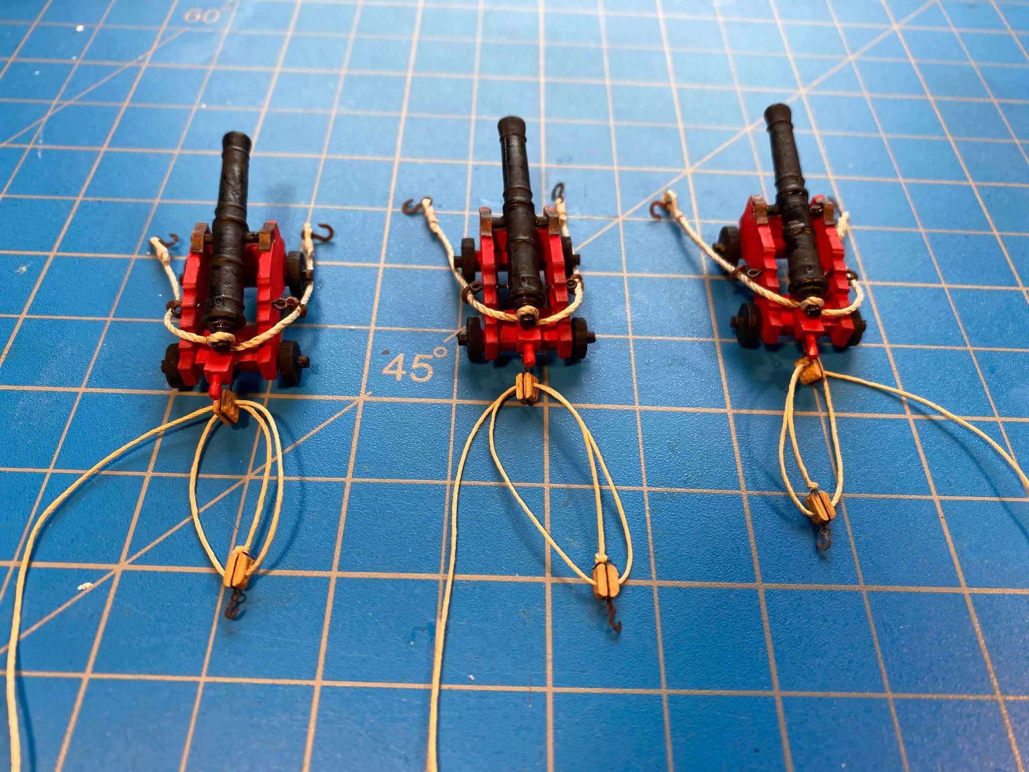
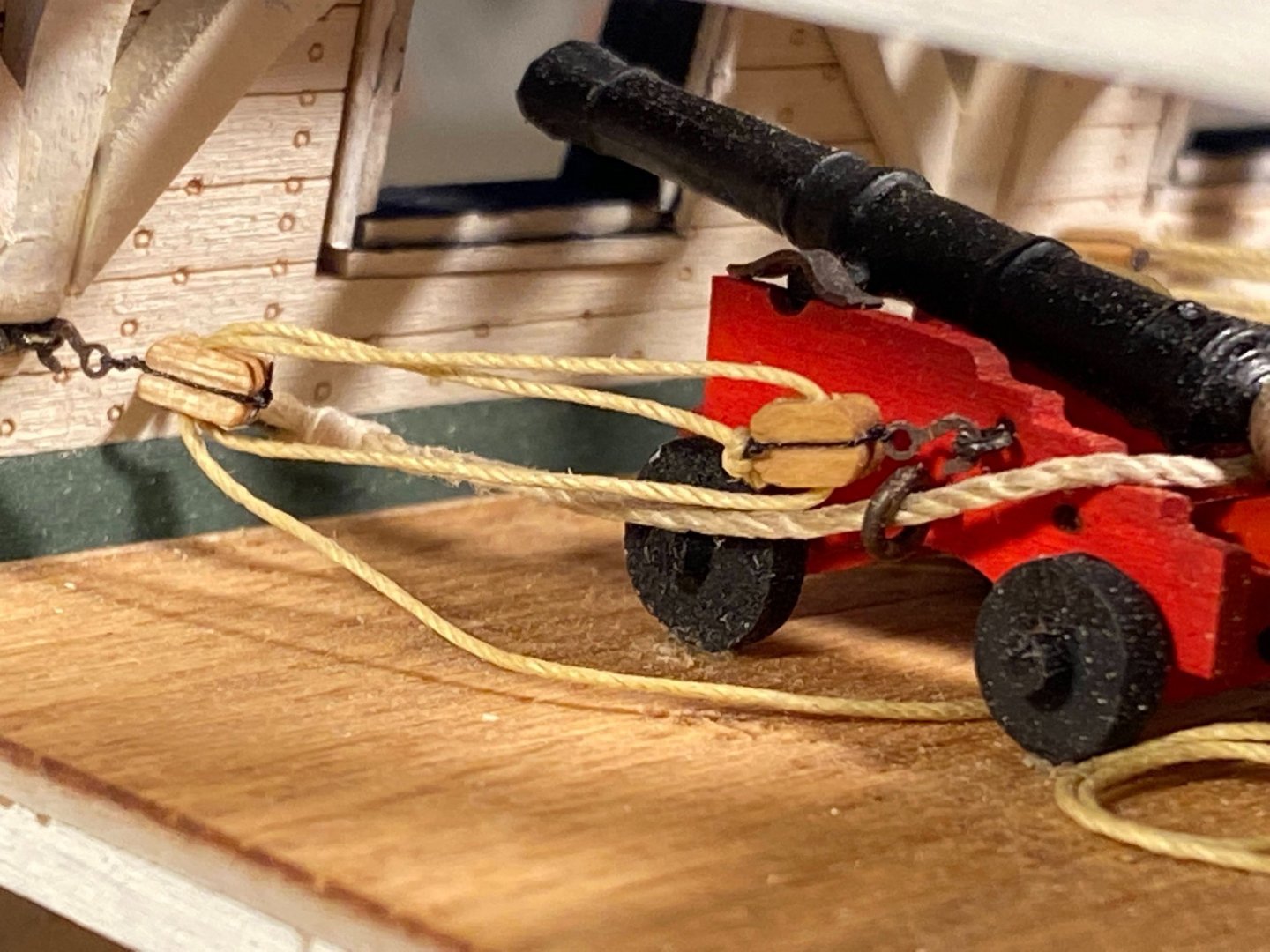
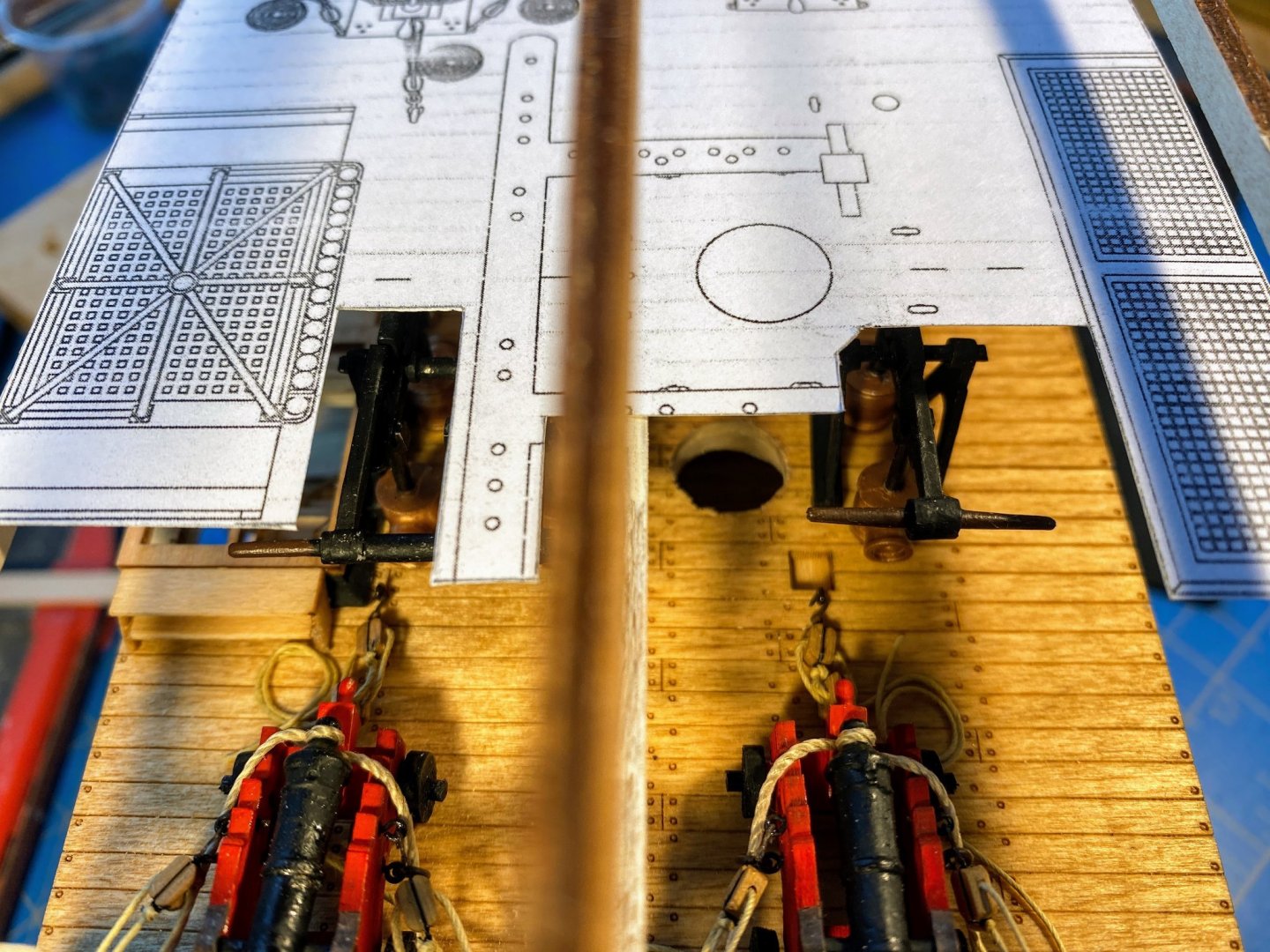
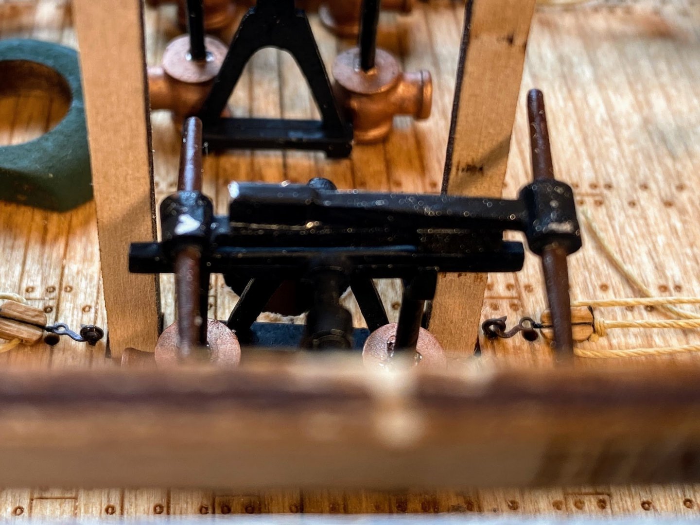
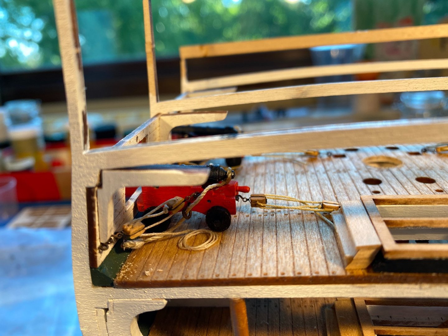
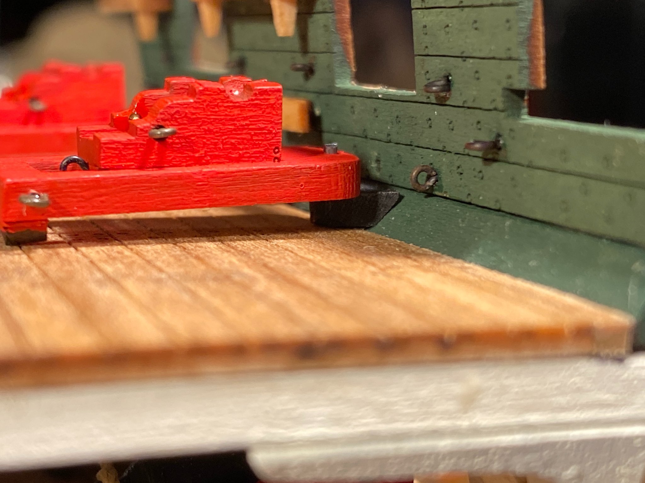
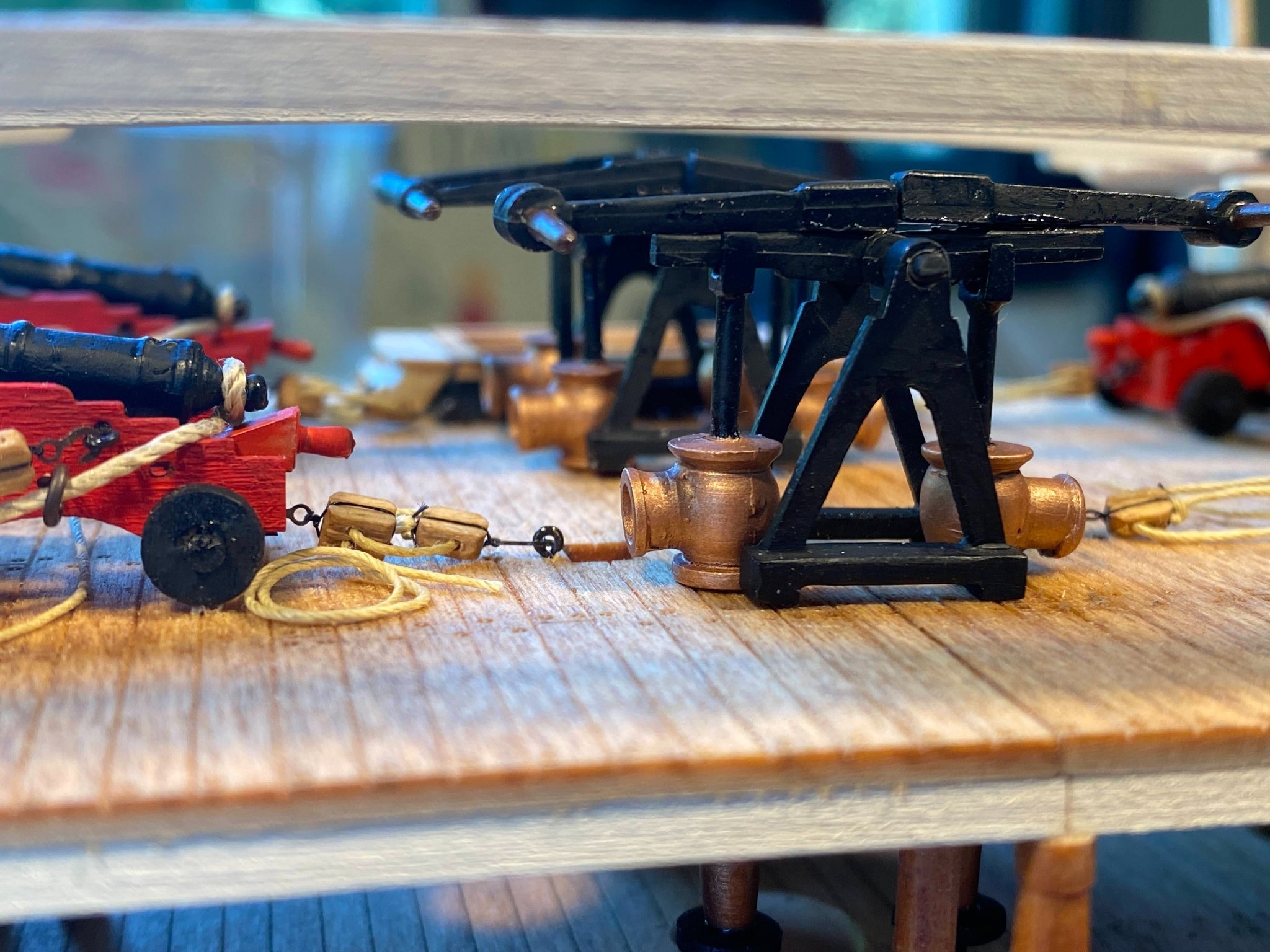
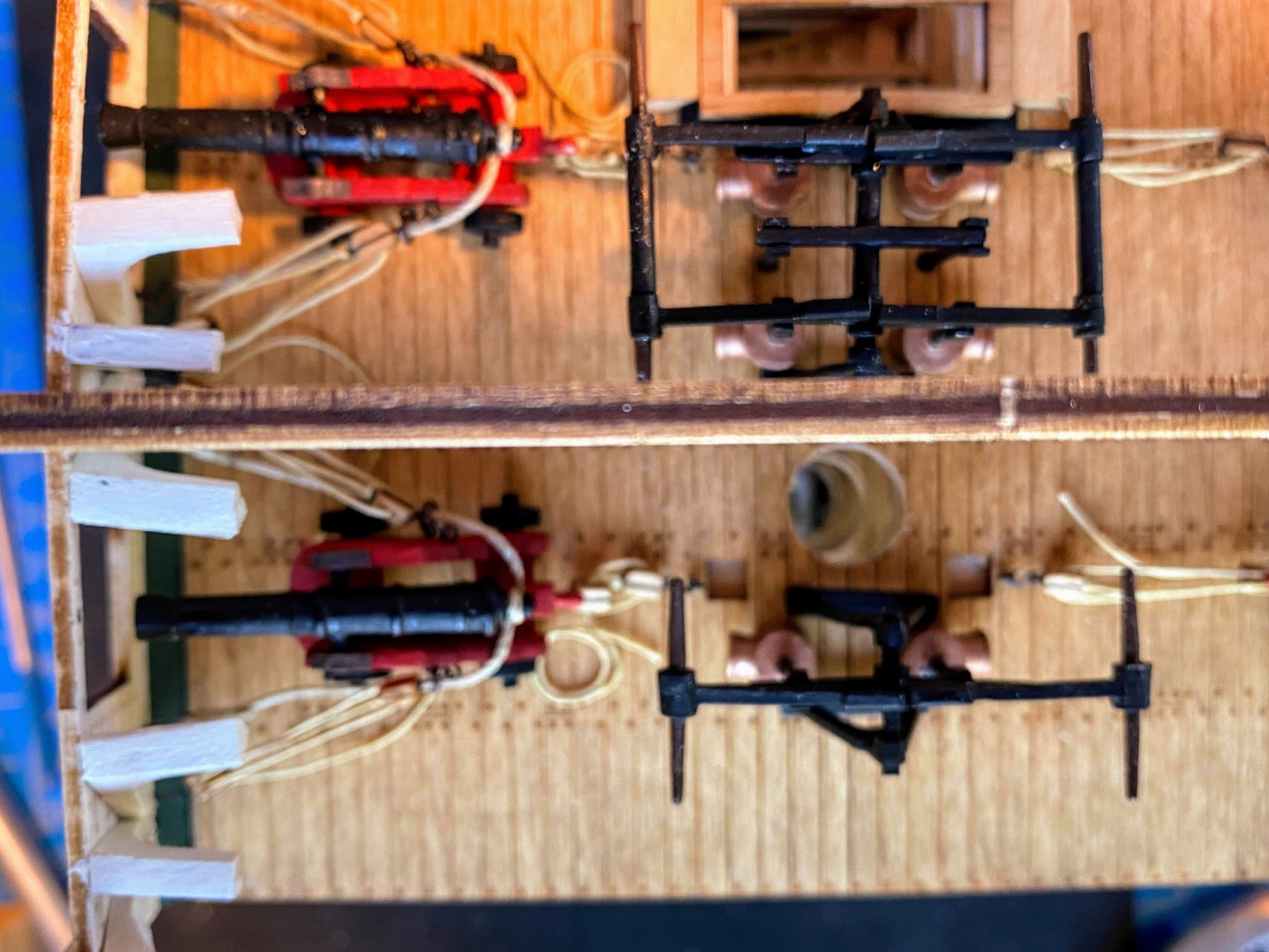
Assembly, painting, and installation of the carronades seemed pretty straightforward for a while, but inevitably things got interesting. The carronade carriages pivot on a pivot base, intended to be affixed to the bottom of the sidewall. Seems straightforward enough, except resting the carriage on a base at that height (i.e. above the top of the waterway) results in the carriage and the cannon pointing skyward at an unreasonable angle. Fortunately I did not glue the pivot bases in place on the port side, where the carronades will be displayed. I sanded the end of each of those bases to a 45 degree angle, then glued them to the waterway and the deck, not the sidewall, and the carriages could then be installed horizontally. Unfortunately I did pin(!) and glue the pivot bases to the starboard sidewall, where no carronades will be installed, and I don’t think there is any way to reposition those pivot bases without doing major damage to the sidewall. Fortunately I doubt that anyone will notice the difference in the placement of the pivot bases port and starboard. Immediately upon trying to add the quoins it was obvious that the kit supplied ones are too large. This is especially the case given the attachment point for the train tackle hook is immediately below where the quoins go, and there isn’t room for both. So I made my own quoins, cut from the end of a 1/16” x 1/8” strip of wood. Shaping something that small proved to be a challenge, and I think I split 5 or 6 pieces before I had two that would do the trick. I made the quoin handles from eyebolts that I painted red, adding an extra large drop of paint to the eye part of the bolt. From a distance they don’t look too bad. One is a bit shorter than the other, since on one carronade there is no room between the cannon and the sled large enough to slip the quoin into. I rigged the breaching lines first, then the train tackles, attaching the latter to the eyebolts at the back of the sleds before gluing the quoins in place. At this point I'm thinking things (including my scratch built quoins) are looking pretty good. Next I made and installed the remaining tackles (carriage and sled) for one of the carronades. With one finished and photographed, I’m realizing that’s quite a rat’s nest of rope the carronade is buried under. Part of the problem is scale -- a 4 mm block on the model translates to a foot long block on the real thing (probably 3 times the real size), and the rigging thread is probably equally oversized as well. But it's a little late to do much about that. The instructions and plans show the falls for the sled tackle wrapped tightly around the tackle itself, which looks pretty nice and tidy, but those tackles need to run free when the gun is fired, which suggests they shouldn’t be wrapped. I’m thinking about replacing the rope coils with smaller ones, and doing away with the coils altogether for the train tackles, since those tackles are fully extended and the falls need not be long enough to coil. And/or maybe I’ll hang a coil or two on the pinrails on the sidewall. Only time will tell how ambitious I get in making the carronade rigging look a little less overwhelming.


- 163 replies
-
- 5
-
-
- Model Shipways
- Constitution
- (and 2 more)
-
The next task in the instructions is gluing laser cut gun port bracing on the outside of the gun deck sidewall ports. Similar bracing (not laser-cut) will be glued to the outside of the spar deck gun ports, and it seemed to me it made sense to do both at the same time, when the spar and gun deck exterior walls are in hand and ready to be installed, as these braces are to fit between the sidewalls and the exterior walls. Apparently the author of the instructions reached the same conclusion, and about half a dozen pages later the instructions have you install the laser-cut gun deck bracing (again) along with the spar deck bracing. So I skipped this step for now. The spar deck sidewalls are quite a project all by themselves. Each one has five eyebolts oriented horizontally, four oriented vertically (plus a fifth in the waterway), a pair of double eyebolts, two carronade pivot bases, two pin rails sharing three “large wood pegs”, a wooden cleat and a lengthwise trim piece painted black. I decided to start with the port sidewall and attach most of these things before gluing the sidewall in place. The one thing I didn’t install on this was is the carronade pivot bases, thinking it would be better to install them once the carronades are assembled and ready to install. A few observations: As I mentioned earlier in this post when working on the gun deck sidewalls, the kit does not come with ready made eyebolts and instead has you make your own out of wire, twisting the wire to make the stem. I have enough eyebolts in my parts bin that I don’t have to do that, but the holes pre-drilled in the sidewall are too large. Previously I had put a drop of thick CA on the stem and pushed it into the holes, but doing so this time I realized I was leaving glue on the surface of the sidewall that wasn’t very attractive. A better approach was to cover the hole with a drop of CA from the back, and then push to eyebolt stem through. I didn't think of that until after completing the port sidewall pictured above, and it needs a little touch up paint. Previously I made double eyebolts by twisting the stems of two single ones together (there is a picture back there somewhere), but I had difficulty doing that this time. Far simpler, I realised, was bending the heads of two eyebolts to the side, then pushing their stems into the hole together side by side without twisting (after having put some glue on the back of the hole). Much easier. As the instructions suggested, I put wire pins in the pin rails to give their attachment to the side wall some strength, and used the pre-drilled holes in the sidewalls. I did the same with the cleat, but had to drill my own hole for that one. Strangely the large wood pegs aren’t described in the instructions until almost 30 pages later (page 59). They would have you make them from 5/32” x 5/32” stock, which you then taper to 1/16” x 1/16” to fit in the square holes in the pin rails. That must be a misprint as 5/32” x 5/32” is way too large, requiring an extraordinary amount of tapering to create the final product. The kit supplies a 3/32” x 3/32” strip (to be used for the cannon axles according to the parts list) and I had plenty left over to use for these pegs. Once I put it all together, glueing the sidewall in place was quite simple and straightforward. And I didn’t get a picture. The starboard sidewall was just the same thing all over again, except for the gap I mentioned previously between the waterway and the middle rib. After a bit of thought and dry fitting, I glued a 1/16” strip to the back of the waterway, let it dry, then glued the sidewall to the waterway, to the insides of the fore and aft ribs, and to the strip. I then applied glue between the outside of the strip and the inside of the middle rib, clamped the same, and pushed the bottom of the sidewall up against the strip, and let everything dry. If the addition of this strip makes the bulwark too wide when it's time to attach the outside wall, I can sand the middle rib down some. Looking at the pictures I realize I forget to add the black trim strip to the starboard sidewall, which I'll do as soon as I finish posting this. Next up is assembly and rigging of the two carronades on the port side.


- 163 replies
-
- 6
-
-
- Model Shipways
- Constitution
- (and 2 more)
-
This screenshot from Google Maps shows pretty well what I was trying to describe in my post last night with regard to the forward hatch, and lack of stairs at the forward end of the model. This is looking forward, and as you can see, the stairs are way forward of anything on the model, which ends at the gangplank seen to the right of the picture. And for those who didn't get it earlier in this log, here's a link to the Google Maps tour of the Constitution: https://www.google.com/maps/@42.3724493,-71.0566215,3a,75y,348.92h,69.87t/data=!3m7!1e1!3m5!1sAF1QipM4G2XOGUOPxXyh5KTrPENhbU6pK3SX4vS-n90P!2e10!3e12!7i13312!8i6656

- 163 replies
-
- 5
-
-
- Model Shipways
- Constitution
- (and 2 more)
-
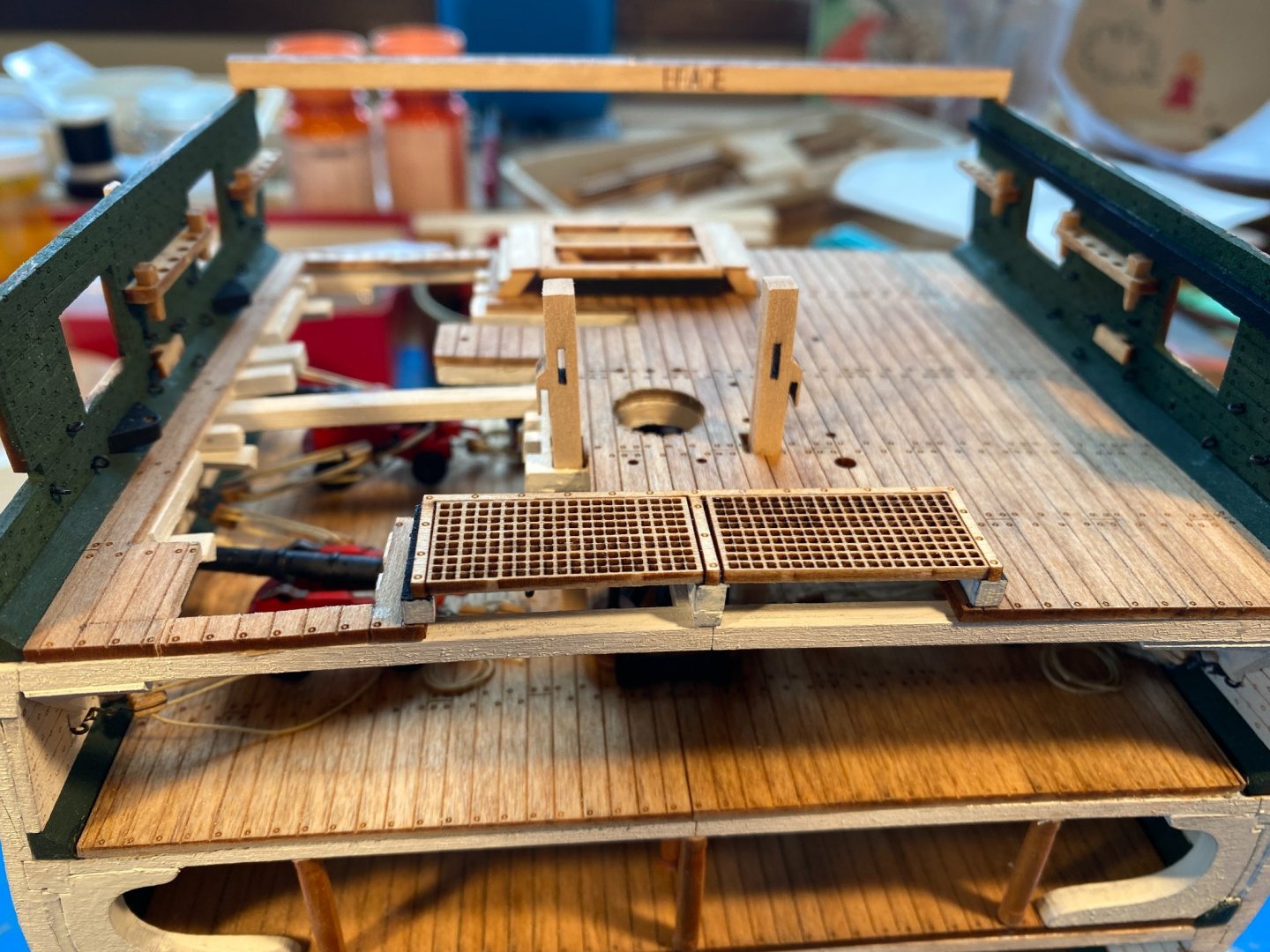
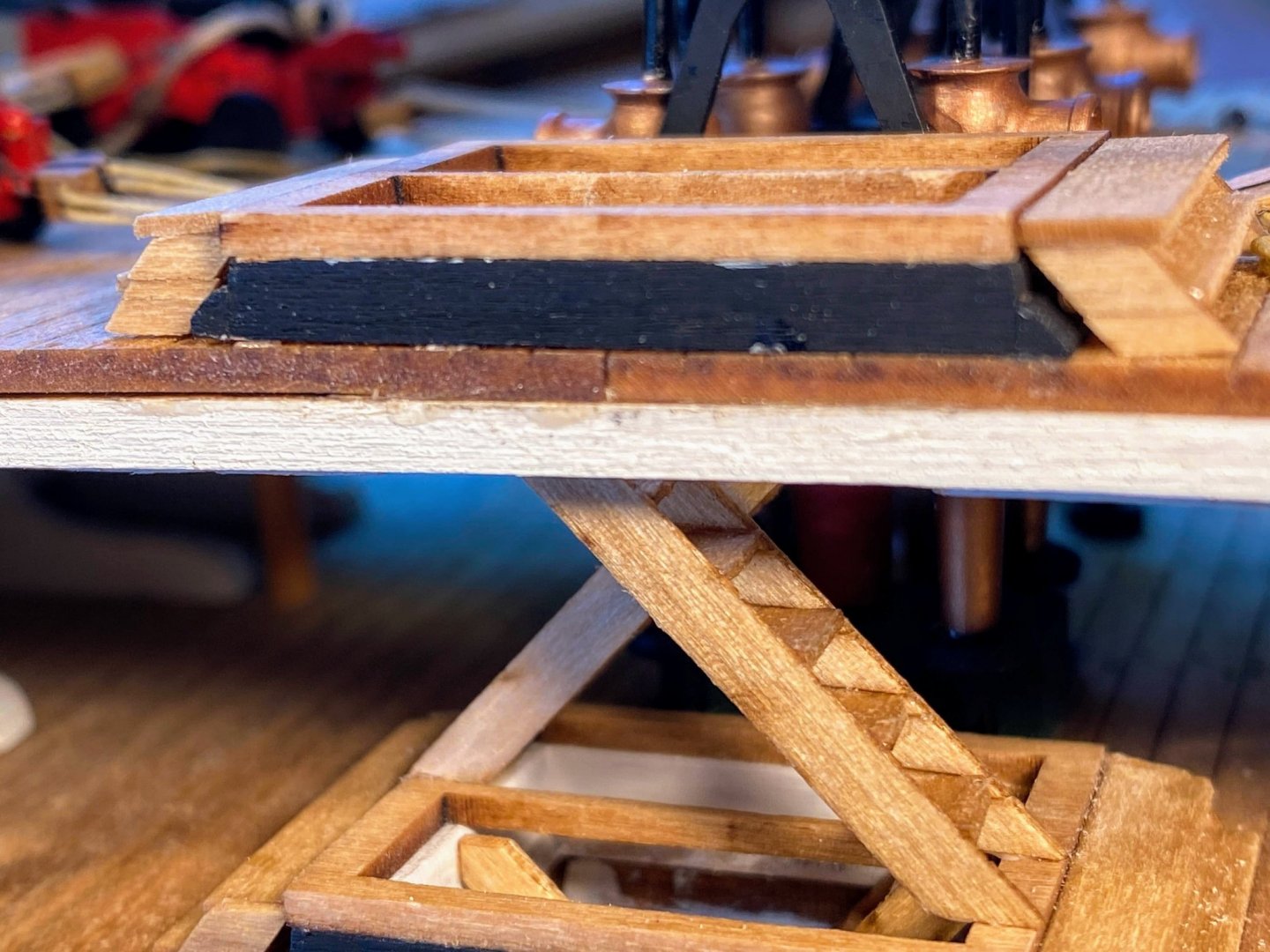
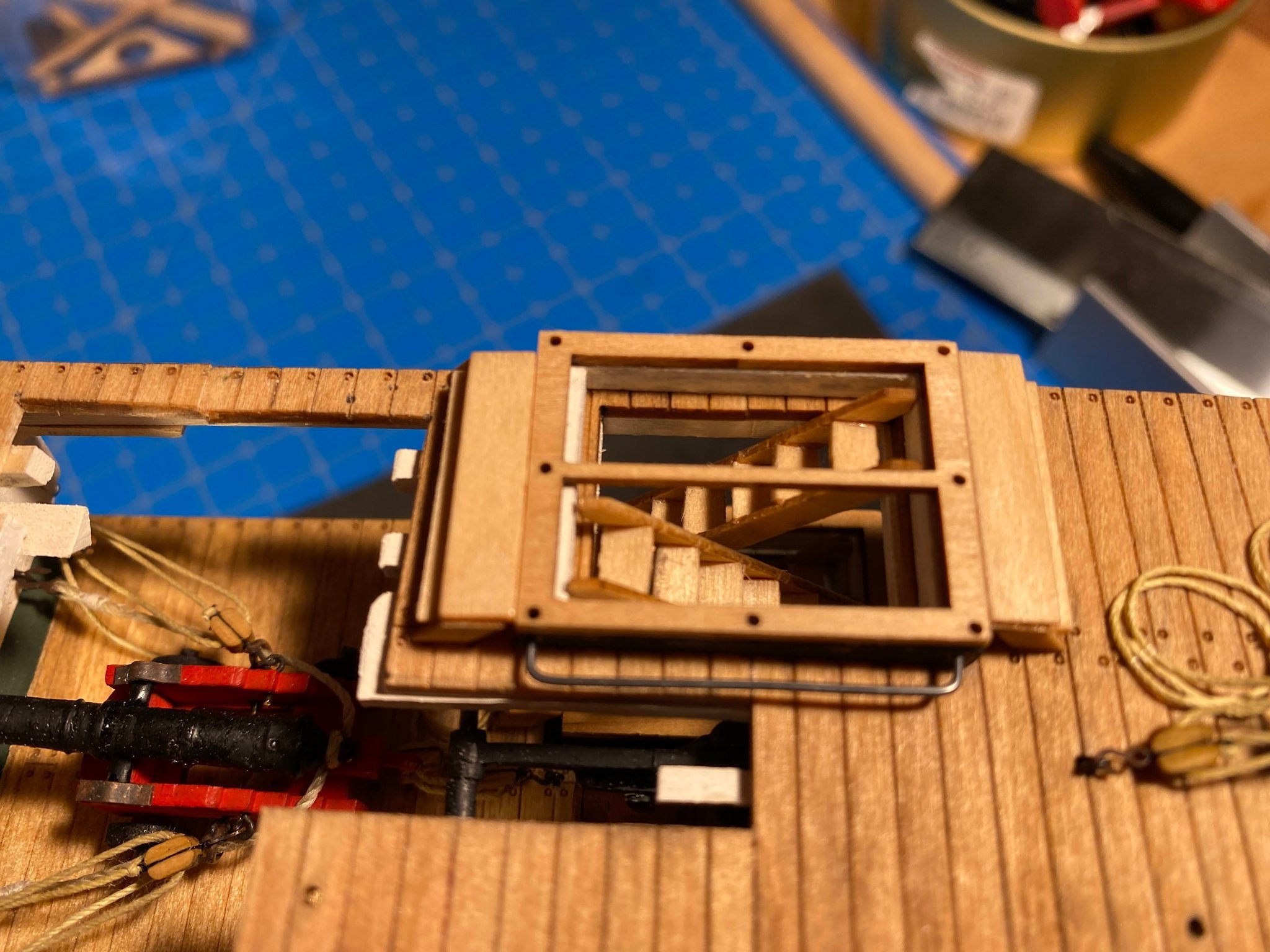
Shaping, painting and installing the waterways was pretty familiar and uneventful, with one exception. On the starboard side the center rib is about 1/8th” out of line with the fore and aft ribs, making a graceful curve which doesn’t match the virtually straight waterway at all. At first I thought I would bend the waterway to fit the rib, but when I dry fit the deck to the waterway, I realized that the deck would need to be shaped pretty drastically to avoid a gap. So I glued the waterway to the frame and other two ribs, leaving a gap between it and the middle rib, which will be hidden between the sidewall and the hull planking. Next came cutting the hole in the starboard spar deck planking piece, to open up a view of some of the gun deck below. That took a lot of time, patience and care, and I still managed to break both thin strips which connect the midships deck and the deck along the waterways. But installing the deck in two pieces actually made things easier. A lot of sanding and trimming needed to be done in order to get the bits and the mast to fit (all dry fit of course) while keeping the front and back of the deck pieces lined up with the edges of the fore and aft framing beams. And of course the two pieces of the deck had to fit between the two waterways, which required some additional trimming where the two broken pieces came together. But fortunately it all worked out. Finally I built, painted and stained, and installed the fore and aft hatch framing. Aft was merely a repeat of what I had done previously on the gun and berthing decks. Steps and stairs still need to be built and installed. Forward things got a bit puzzling. The instructions and Plan Sheet 1 show a pair of stairs leading up to the spar deck, athwartships but not crossing each other as is the case with the aft stairs. Plan Sheet 2 doesn’t show any forward stairs but does show grating filling both the aft and forward hatch areas, blocking access to any stairs. Looking at the Google Maps views of the ship, it appears that the forward hatch which is part of the model is part of a large hatchway, maybe 15 feet long or so, covered with grating, most of which extends forward beyond what can be shown in this model. At the forward end of the hatch is a pair of stairs which run fore and aft rather than athwartships. I decided that any such stairs, however oriented, are beyond the scope of this model, and I covered the part of the forward hatch that is part of this model with grating. I don't plan to install any stairs forward. Then before taking the following pictures, I cut off the forward brace running betwen the forward ribs . . . a milestone of sorts.


- 163 replies
-
- 6
-
-
-
- Model Shipways
- Constitution
- (and 2 more)
-
Well, I got my nerve up and made a bunch of cuts to the spar deck framing, and nothing bad happened. 😄 But as I dry fit the four resulting pieces, I realized more than before that I should have taken greater care installing the gun deck knees. I should have shaped and installed them with the framing pieces in hand, to assure that they joined the frames appropriately. Instead, one is fairly crooked, and the tops of several are not in the same plane with the bottoms of the frames, and they don’t line up correctly with the individual frames. I’ve been tempted to remove and reinstall the crooked one, but it seems to be pretty firmly attached to the sidewall, and I don’t want to risk damage to the sidewall removing it. A common theme on these boards is having a loved one say “You’re the only person on the planet who will ever notice that”, and I’m hoping this is such a case. Also, I noticed on that great Google Maps tour of the real ship that the daigonal knees are supposed to join the sides of the frames (vertically) rather than the bottoms (horizontally) as shown in the instructions, and for a moment I wondered if I should have tried that. But then I realized that the model frames have a fairly wide section running fore and aft along the sides of the hull, and each knee would need a large notch to accomodate that part of the frame, and I decided that just wouldn't work on this model. EDIT a week later. Test fit the bits in the square holes in the framing before gluing the framing in place. I found the holes to be slightly too small, and it would have been a lot easier to enlarge them before they were glued to the ship. In any event, I did a lot more shaving and sanding to try to improve on the frame/knee interface, and finally glued everything in place. And then I laid my paper deck on top and decided I can live with the result. Next up, carve and install the waterways (the final time for this build!), cut the big hole in the deck, and glue it in place.


- 163 replies
-
- 7
-
-
- Model Shipways
- Constitution
- (and 2 more)
-
Good times the last few weeks, but good to be back in the shipyard. Beginning to work on the spar deck and its framing, I realised I had a problem I wish I had noticed earlier. The gun deck sidewalls need to be trimmed a bit at the top, which I could have done easily before installing the knees. With the sidewalls and the knees being higher than they should be, the framing will extend above the beams, leaving a gap between the beams and the spar deck planking. The picture below shows the problem if you look carefully, but the problem was more noticeable, and was somewhat remedied, before I took any pictures. Bottom line is that I ended up doing a lot of tedious sanding of the sidewalls and the tops of the knees, as well as sanding and thinning the framing. Getting tired of doing that job, I decided to make some decisions about cutting out most of the starboard half of the spar deck to reveal the guns, the pumps and other detail on the gun deck below. First thing I did was scan and print the portion of the plans which is a top down view of the spar deck. Then I cut out of the printed copy the portion of the starboard side corresponding to the portion of the deck I want to remove. I laid the paper on top of the beams to get an idea of what will be revealed by the cut out portion of the deck. Next I laid the paper on top of the framing and made some preliminary decisions on where the frames will be cut. I want enough of them to extend a little beyond the deck to give an idea of what the framing entails, without interfering too much with the view of the gundeck below. Probably the most intimidating thing I do in this build will be that first piece of framing I cut. Coming up soon . . .


- 163 replies
-
- 5
-
-
- Model Shipways
- Constitution
- (and 2 more)
-
Thanks for your observations Jon; definitely appreciated. I too wanted to show the handles in action position rather than stowed, but as you said they can't be attached to the ends of the rocker arms with the fittings as supplied as would have been done on the real ship. And even if I could to that, they would have extended way too far outward, over the cannon carriages. So I figured that stacked with handles outward was the only option, even though not historically accurate. As you say, most observers won't ever notice. All of which is easy to rationalize after the fact. Had I realized how out of scale the fittings are at the time of asembly, maybe I could have come up with a creative solution. Your scratch built ones are really outstanding. I don't think I have the skills or patience for that.
-
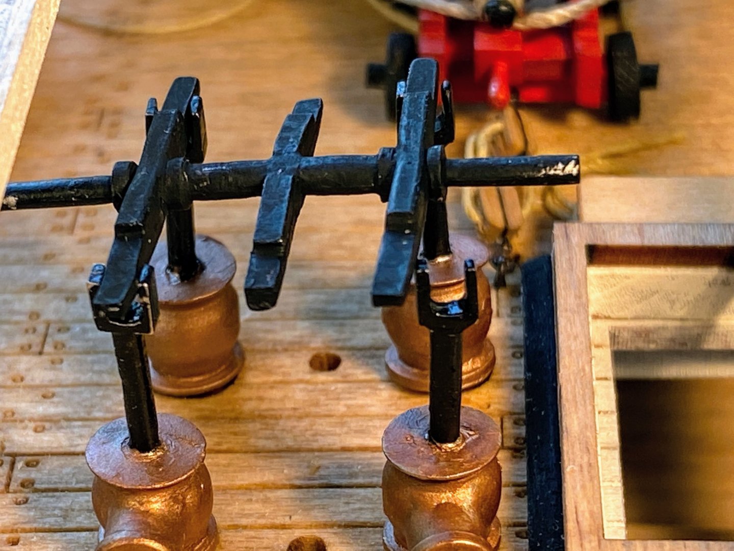
The plans and the photos in the instructions show the handles for the pumps folded back on themselves in some fashion, obviously for storage. Less obvious is exactly how this is done in real life, and stacking them as I did in the first photo below (dry fit) just didn’t look right to me. Nor did it make sense to me why one handle (on the single pump) would be inside the bits coming down from above and the other would be on the outside. I had not yet seen the great Google Maps tour of the Constitution Tom (usedtosail) so kindly alerted us to above. Looking at the second picture below I now realize that the handles on the ship slide onto the ends of the handle arms (or rocker arms as I described them previously) when in use, and they are indeed stacked on top of those arms when stored. Part of what made this look awkward to me is the bulge at the inboard end of the handle arms. Didn’t look right (IMHO) so I ground one side off so the handles can lie flat on top of the arms, and glued them in place as shown below. Actually I’m not sure I would have done differently even if I had seen the virtual tour of the real thing before glueing the handles in place. Looking at the photos above, I’ve come to think the whole pump assemblies may be a little too large. Had I been able to slide the handle parts onto the ends of the handle arms as appears to be done on the real ship, the handles themselves would have been above the cannon carriages (especially the cannons stored inboard), leaving no good place to stand while working the pumps. Also the whole things as assembled come close to the height of the beams for the deck above, meaning they would have been at maybe face level relative to an average height man, which certainly doesn’t look very ergonomically efficient. A flaw, though, that is not likely to be noticed by anyone not building the model. Not relevant to any of this, but I have mentioned previously that the laser cut wood parts are very well cut. As an example, the bits referred to above have a couple of tiny sheaves above decks that would be very difficult to cut with a hobby knife. But upon slicing the tabs that hold the bits to the sheets they come attached to, they dropped very neatly onto my work bench without any hang up on the outboard sheave. Nice work Model Shipways. Finally, assembling the aft stairs went well, using the jig I posted a picture of back at the end of May. When I installed the gun deck framing more recently, there was some discussion about whether a small section of one of the beams would need to be removed to make room for the stairs. That proved to be the case for me. A combination of Xacto knives with a conventional blade and a saw blade, along with some small sanding implements, got the job done. The stairs then fit nicely into place. It may be a few weeks before I post again . . . houseguests coming, a little travel, a very minor medical procedure, and a few projects that need to be completed before cold weather settles in. But perhaps most of all, I need to do some thinking about exactly how I am going to cut the starboard spar deck framing and planking pieces so as to best show the gun deck below while giving a hint at the framing that underlies all these decks. It will be fun.

- 163 replies
-
- 5
-
-
- Model Shipways
- Constitution
- (and 2 more)
-
Hey Bob, glad to see you're getting back into the model shipyard. And happy birthday! Hope you have a great trip to the City. I grew up as a Giants fan and remember (barely) watching them at Seals Stadium before Candlestick was built. But baseball doesn't interest me much any more (maybe because the nearest MLB team is the Mariners ☹️), but that's OK, I watch Sounders and some international soccer, grand slam tennis, Tour de France and of course Gonzaga basketball. Nice thing about being our age is that we have much greater freedom to do what pleases us, including stepping out of the shipyard for a while and pursuing other passions. Kudos for doing that.
-
Thank you for the link Tom. What a great resource. This reminds me of a morning quite a few years ago when I picked up the paper and read an article that began with a warning that read something like "Don't read this if you are at the office and needing to get some work done." That described my situation exactly, but I of course read on anyway, about a new fangled program or site called Google Earth. And as was predicted my work day was delayed by an hour or two. Same thing with this site, difference being I'm semi-retired, working from home, and can afford enjoyable distriactions like this. And distracted I was. 😊 Thanks again.
- 163 replies
-
- 2
-
-

-
- Model Shipways
- Constitution
- (and 2 more)
-
Jon and Bob, thank you both for your kind offers. Given where I am in the build, I've probably done what damage I can do without having the benefit of photos, but maybe when I get up on the spar deck (I keep thinking of it as the sunshine deck😎), I'll think of something I want to take a look at. Jon, I couldn't agree more with your observation about seeing Boston from a car, and I would apply that to just about any major metropolitan area. We have been fortunate enough to travel to several large cities around the globe, and there is nothing I enjoy more than exploring them on foot. About the only time I've spent driving in a large unfamiliar city is picking up a rental car to get out of town (and the reverse coming into town), and usually I find the experience to be at best inconvenient and more frequently frightening.
- 163 replies
-
- 2
-
-
- Model Shipways
- Constitution
- (and 2 more)
-
Thank you Bob and Jon. Jon, I spent the last hour or so reading your log from the pumps onward; I guess that's almost a year's worth of amazing work. Your scratch built detail is extraordinary; a pay grade or three (or more) above my abilities. Your log is now on my follow list. I bought my kit mid-summer last year (when it was on sale), and it's too bad you weren't aware of it when you could have canabalized a bunch of parts. I see you have a bunch of pictures of the real thing, especially below decks. Did you take those? I looked on the internet a bit for photos like that but didn't find much; only exteriors. My wife and I had some vague plans to go to Boston last month, but like so many other travel plans these days, they never materialized. Thanks for your great log.
- 163 replies
-
- 2
-
-
- Model Shipways
- Constitution
- (and 2 more)
-
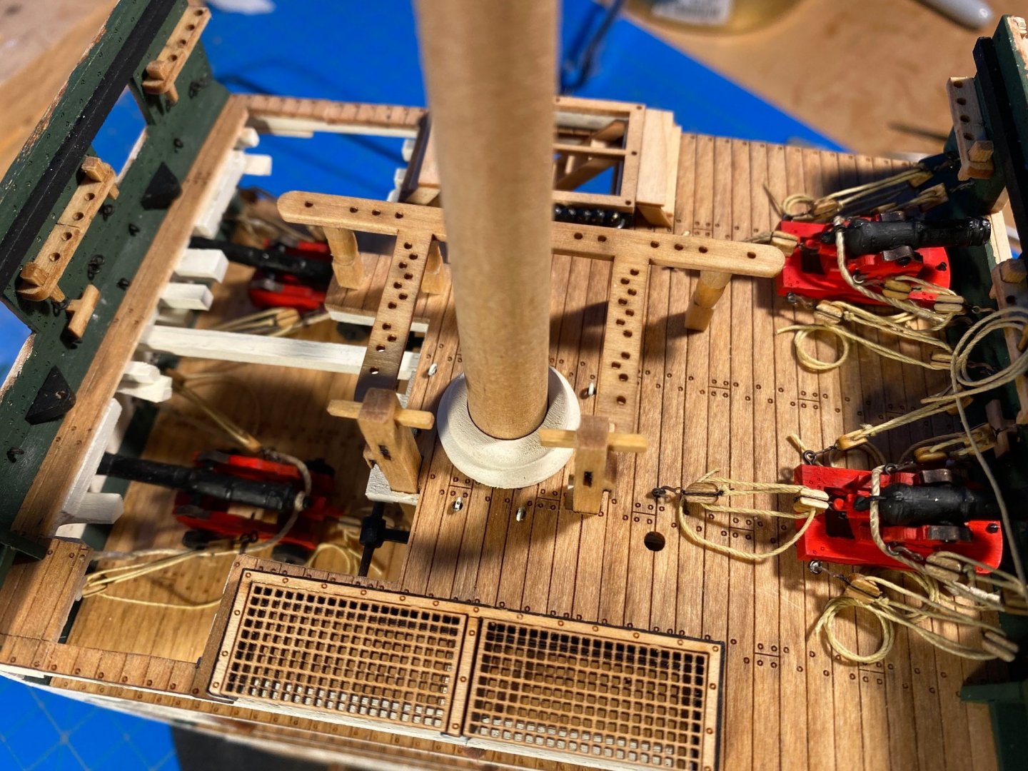
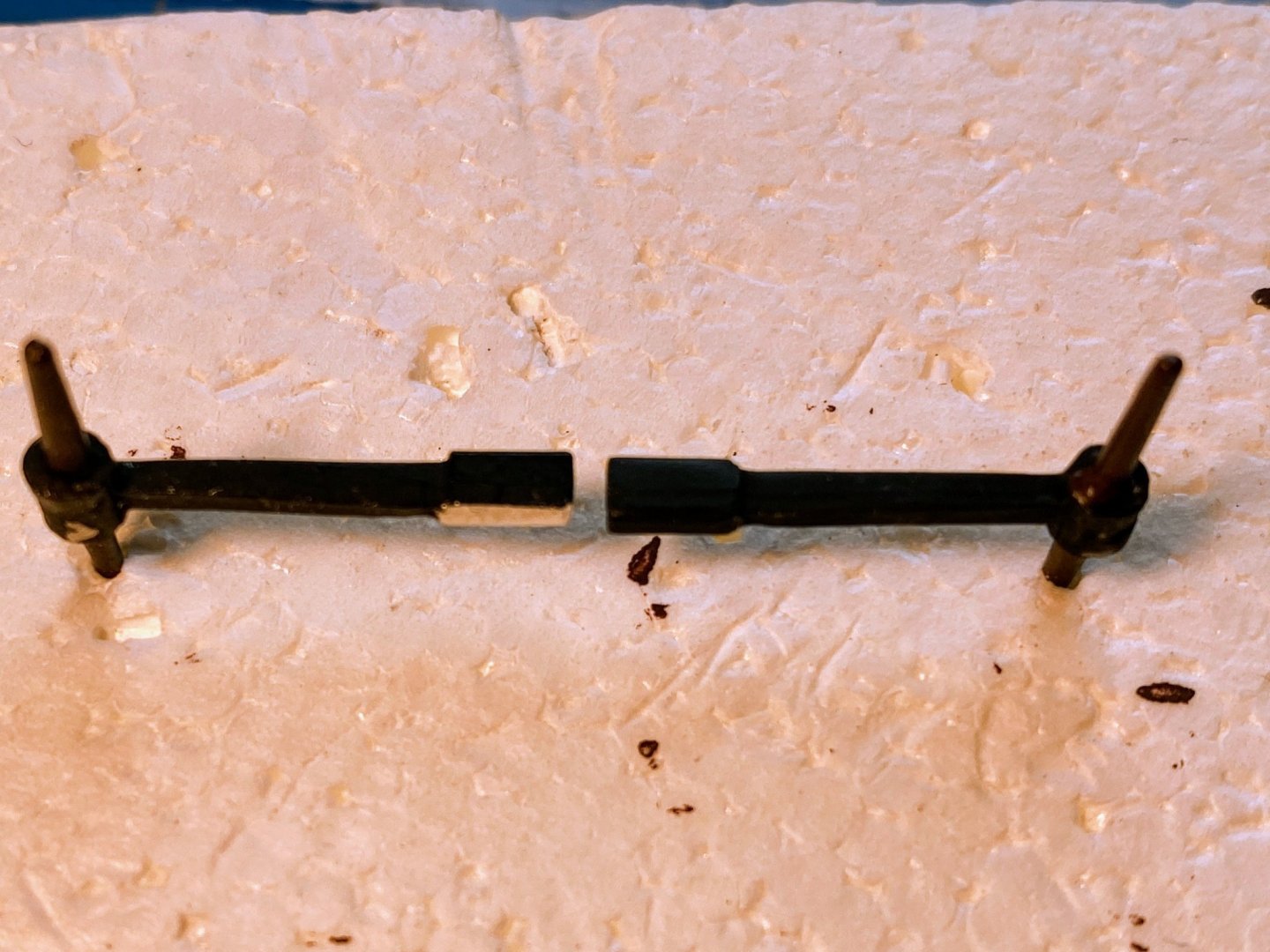
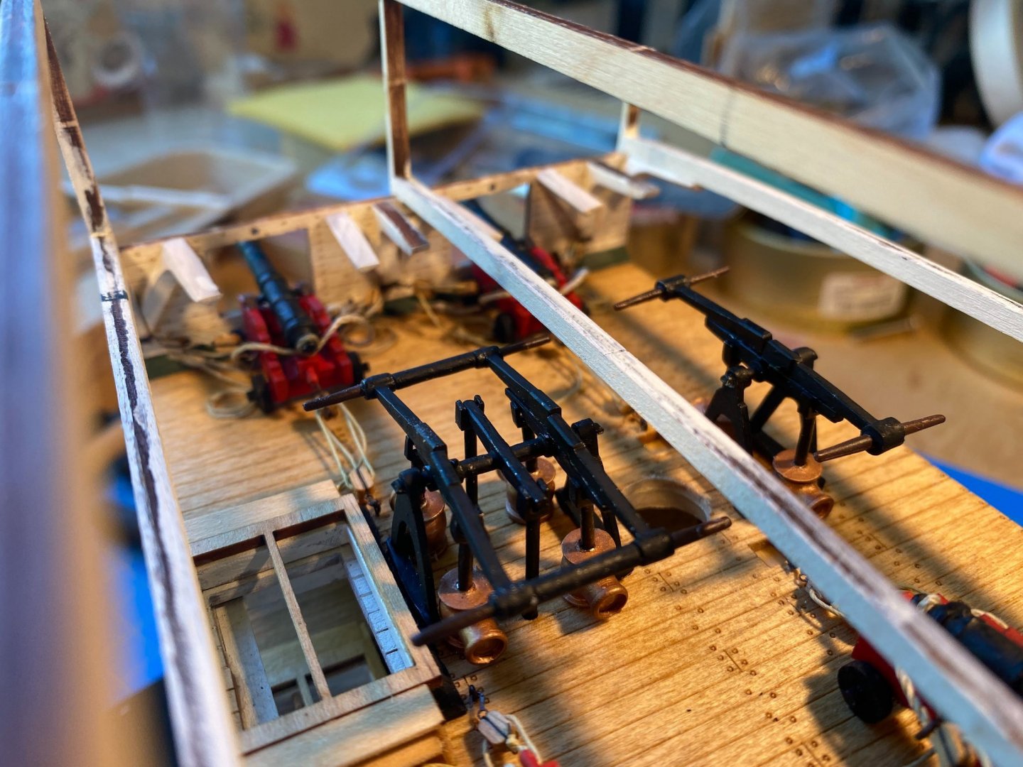
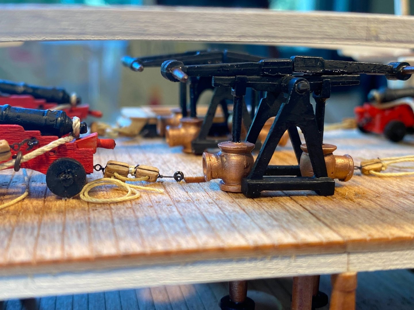
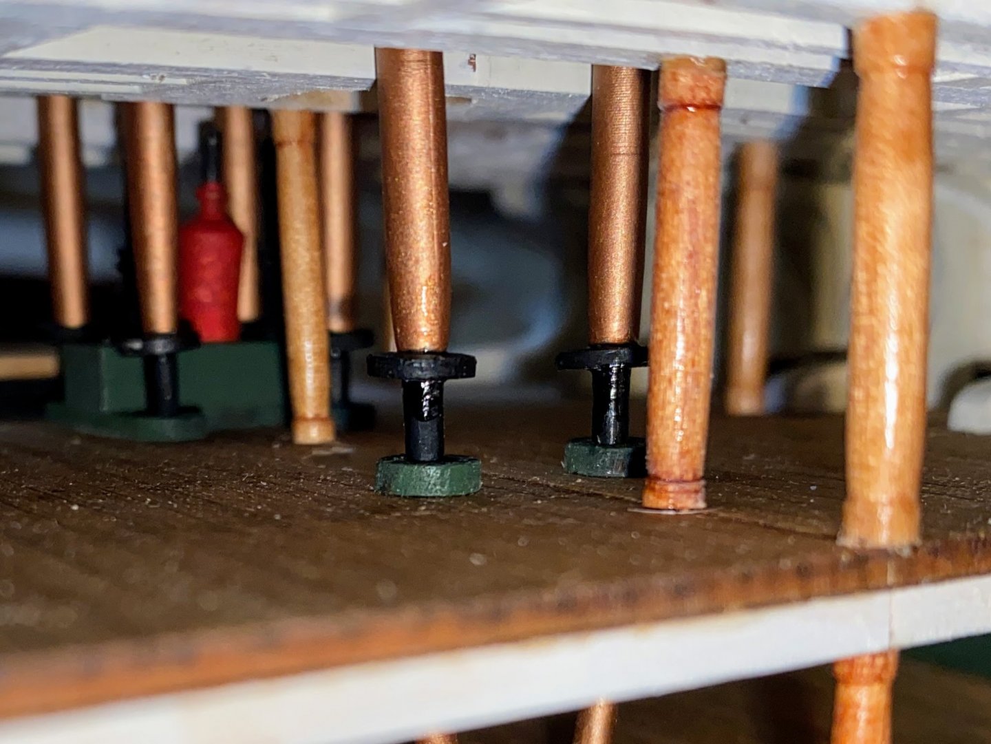
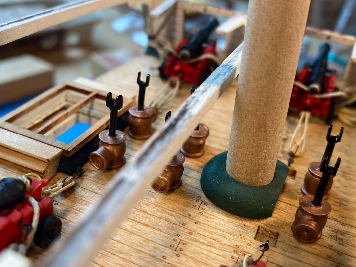
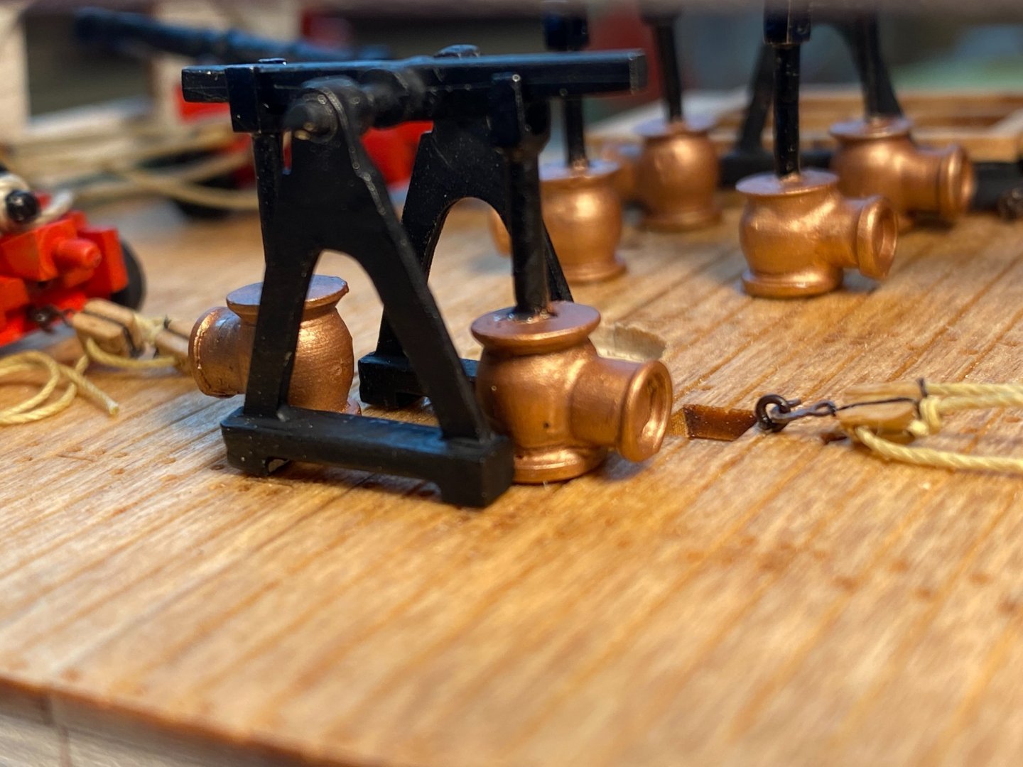
On most models where you would be working on an open deck, assembling and installing the pumps would probably be pretty straightforward. Much less so here as there is almost always something in the way of what you’re trying to do. First thing is installing the metal flanges onto the lower part of the six metal pump assemblies, which occurs between the berthing deck and the gun deck. Quality tweezers are a big help; nevertheless I bet I dropped a flange more than a dozen times. I applied some medium thick CA to the pump assembly shaft where the flange would be, carefully lowered the shaft through the hole in the gun deck, then slid the flange onto that shaft and slid it up to the glue. Unfortunately some of the glue is visible in the first picture below, but hardly visible to the naked eye in normal light. Then I glued the assemblies in place, with a drop of the same CA applied to the bottom of the pump assembly shaft and to the underside of the assembly where it rests on the gun deck. You definitely want to start with the middle pair, so the ones closer to the end are not in the way. In fact I fully installed the four assemblies which are part of the aft double pumps before doing anything with the forward single pumps. The pump handle assemblies consist of triangular “pump base frames” on either end, “pump arms” attached to a shaft or axle which rotates (on the real thing only) in the base frames, “pump handles” which are pretty much what you would expect, and on the double pump, a pair of “center linkage arms” which go through the deck to operate the pumps you installed a while ago on the berthing deck. No way the shafts for the latter link with these "linkage arms" on the model, but the gap is well hidden by the gun deck and framing. Oddly there are two double and two single pump arms supplied when only one of each is needed, and there are six linkage arms when only two are needed. “Rocker arms” sounds more descriptive to me so I will use that term instead of "pump arms". I started with the double pump, thinking installing it on the rods coming out of the top of the installed pumps would be pretty straightforward. Until I tried dry fitting it in place. . . As you can see every piece has to be bent and placed perfectly for things to fit, and the ends of the axle need to be cut slightly shorter. And of course bending these things mars the paint, which I decided not to touch up until everything was installed. At this point I decided to do the simpler, single pumps first. After doing a lot of dry fitting, I decided to glue the base frames onto the rocker arm axle ends first, then glue the assembly to the deck and the pump rods. That went quite well. Back to the double pumps and another problem. There is simply no room for the aft base frame to fit between the aft pumps and the stairway frame combing. After giving the situation a lot of thought, I tried thinning the base of the "frame base" with a dremel tool, trying to get the base down to the thickness of the frame. That went remarkably well. For good measure I carved away part of the combing too, which was much harder to do and looks pretty messy. Fortunately that part will be well hidden when this is all finished. With that fit issue (and all other ones) resolved, and having determined that the “center linkage arms” could be installed later, I slid the slimmed down aft pump frame onto the aft rocker arm axle but did not glue it, applied CA to the bottom of the frame and to the brackets on top of the pump rods, put everything into place, then added a drop of CA to the rocker arm axel, and heaved a sigh of relief. With that all dry, I then slid the forward frame onto the forward end of the rocker arm axle, and glued it in place. To my surprise, the frame ended up hanging about a millimeter above the deck, because I had not pushed the rocker arms far enough down into the brackets which hold them. Fortunately an almost invisible flaw. I then dry fit the 2 center linkage arms in place that I had painted and discovered the rod on one was too short. I glued the one that fit in place and took the following picture. After I had painted another linkage arm (thank goodness for the spares), glued that in place, did some touch up of the paint, and took this picture, feeling pretty good about the end result. As suggested in the instructions I dry fit the laser cut bit posts into the holes they will rest in in the deck. I also put the mast surround in place to see how it fits. Bottom line is this deck is getting very crowded, and more than once working on it reminded me of one of my favorite Gary Larson cartoons. My now-retired dentist had it pasted on the ceiling, the first thing you saw as he reclined the operatory chair.😁 Next up . . . pump handles.

.thumb.jpg.1addca643fd82cae6c247bd1f028b041.jpg)

- 163 replies
-
- 6
-
-
-
- Model Shipways
- Constitution
- (and 2 more)
-
The knees are finished and installed. Lots of carving, sanding, shaping and painting. And then gluing in place, perhaps the most challenging part of all, given the cramped space to work in. I still think I made the right decision by finishing the guns first, but there were times I questioned the wisdom of doing so. The first issue I encountered concerned the aft knees, which fit under the aft beam. But they don’t fit, for two reasons. First, there is a bump that is part of the joint where the beam meets the rib. I first tried to cut a notch in the knee to accommodate the bump, but that didn’t go very well. Cutting and filing the bump away worked better. Second, the side wall twists some as it comes aft, with the result that the knee doesn’t angle up slightly as the beam does. Fortunately there are several extra diagonal knees, which have a lot more wood on them to work with. With some shaving and sanding I got them to fit reasonably well. The middle knee has the same problem, but to a lesser degree. Next challenge came when I was using some long, heavy tweezers to fit one of the diagonal knees in place. When I dropped the tweezers (as was inevitable), I broke loose one of the gun tackles from its hook in the sidewall. On closer examination I realized that there was no way I was going to get that hook out, rig a new tackle, and hook it back in place. Instead I gently disengaged the carriage hook, keeping the tackle as intact as possible (a big help was the diluted white glue I had applied to all the thread after it was installed). Somehow I then tied the orphan block back onto its embedded hook, hooked the other end back onto the carriage, and it all looked good as new (right cannon in the photos below). I was less happy with how the knees on that side looked when glued. They look a little sloppy, but fortunately will be largely hidden by the deck above. I mentioned previously that I have decided to cut away most of the starboard side spar deck and deck framing, to make at least some of the gun deck visible from above. Consistent with that decision, I cut the horizontal arms of those knees back to ½”. A stub of that arm will extend a little bit beyond the waterway and a narrow bit of deck and deck framing. This time I did a better job of shaping the knees, and these more visible knees look better than the more hidden ones on the other side. Pumps are next . . . .


- 163 replies
-
- 6
-
-
- Model Shipways
- Constitution
- (and 2 more)
-
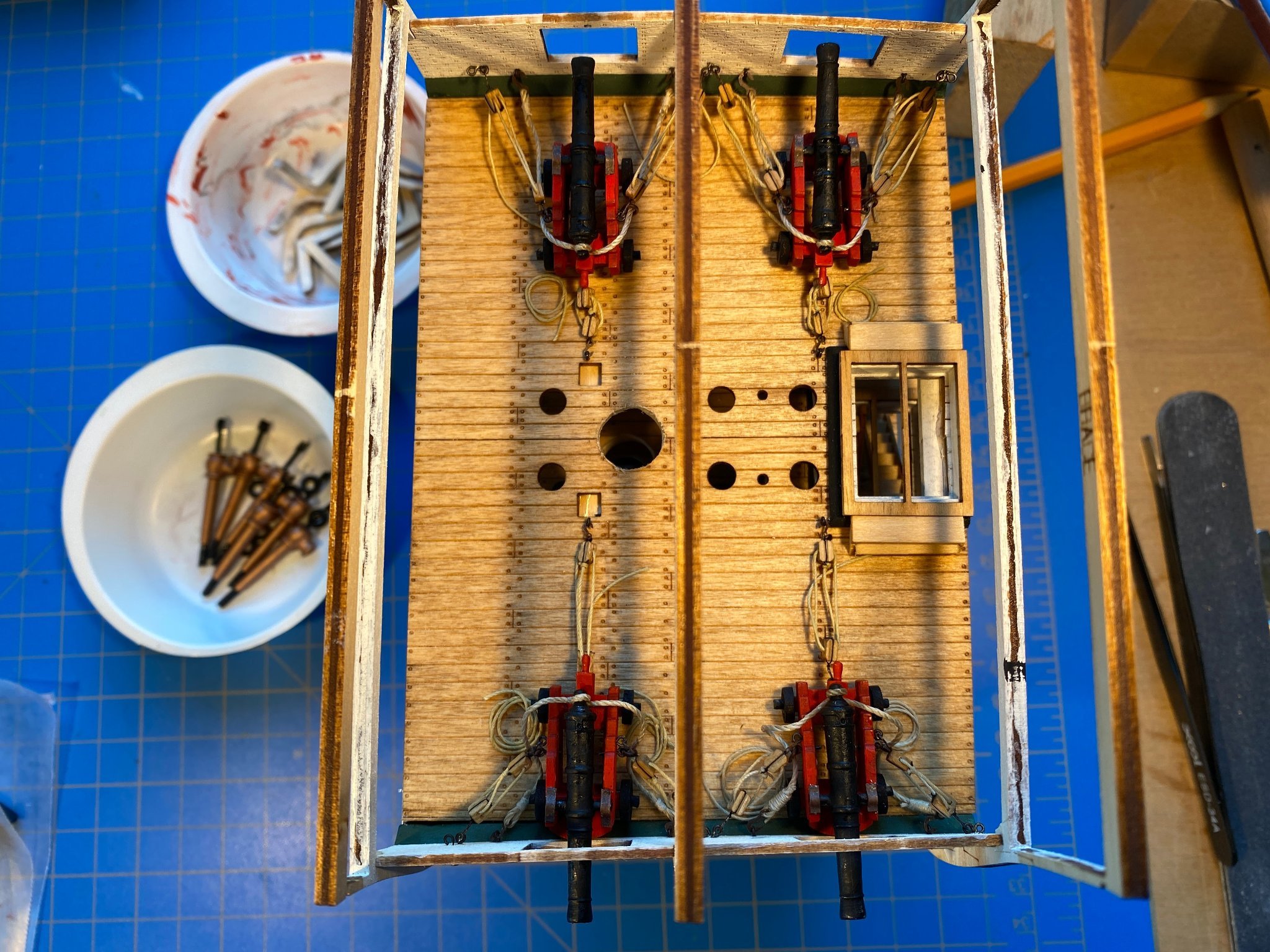
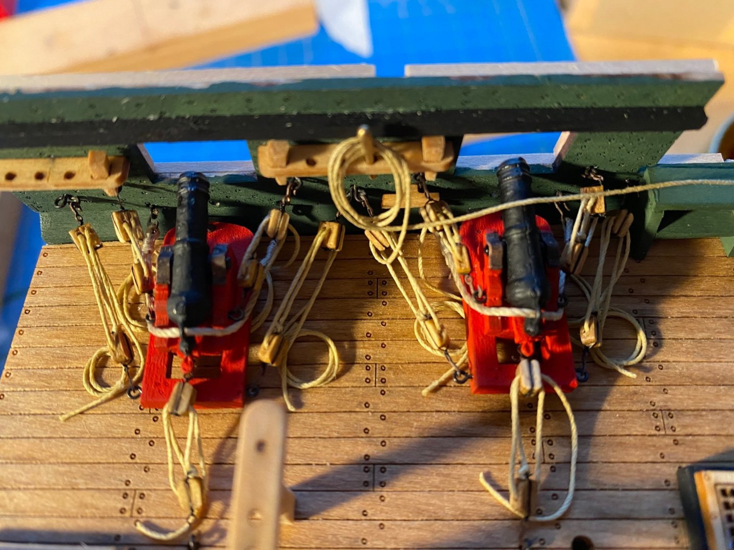
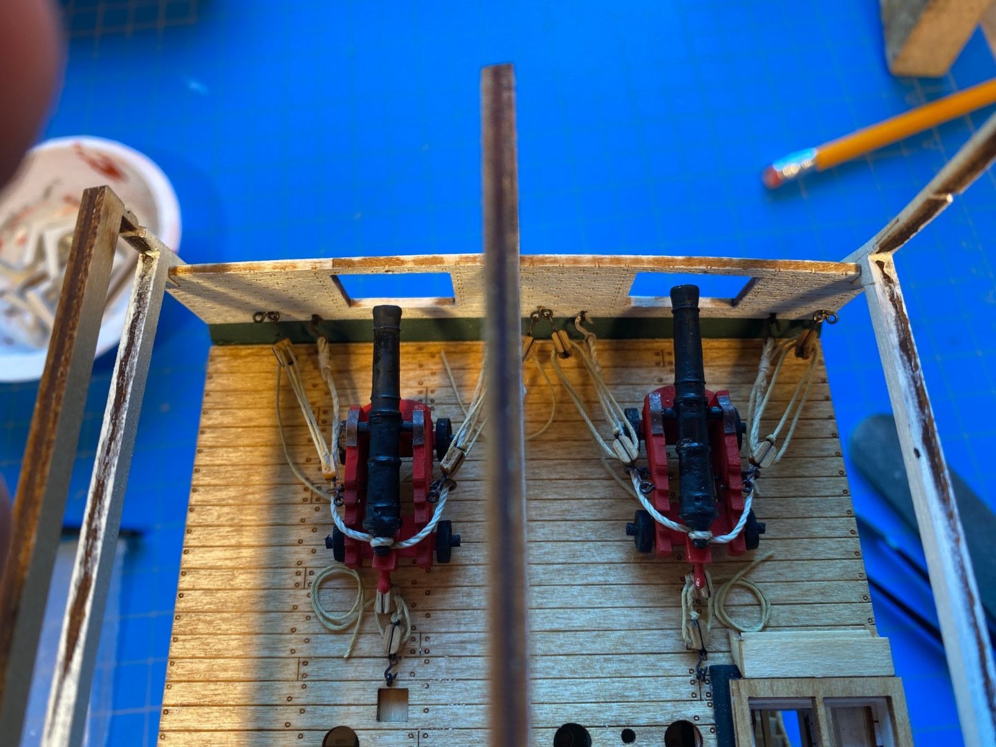
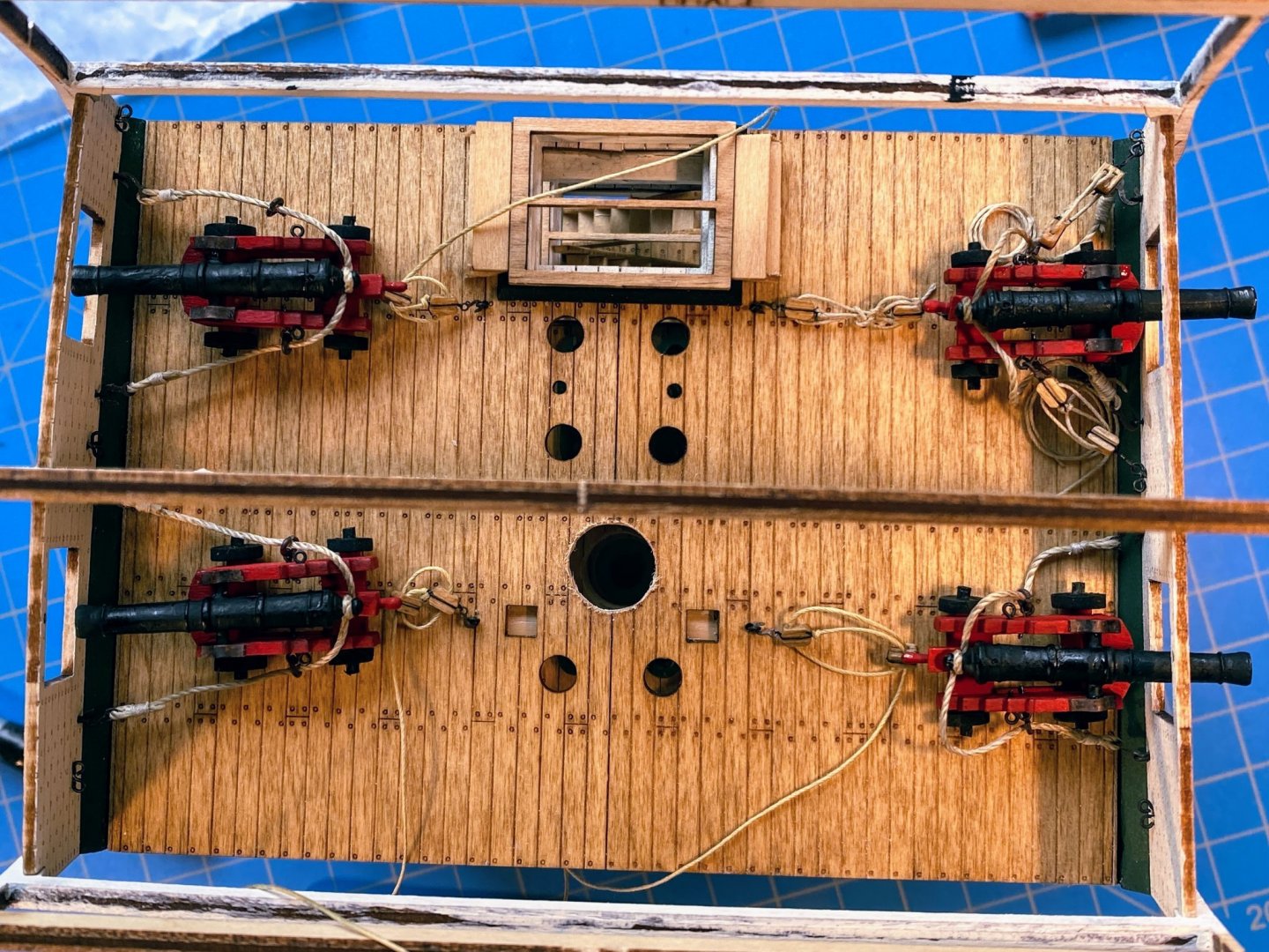
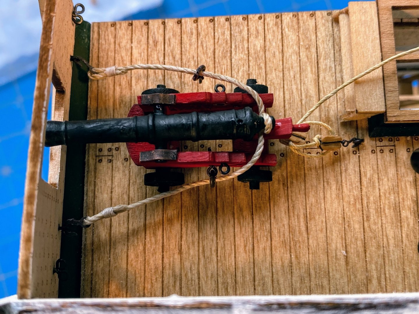
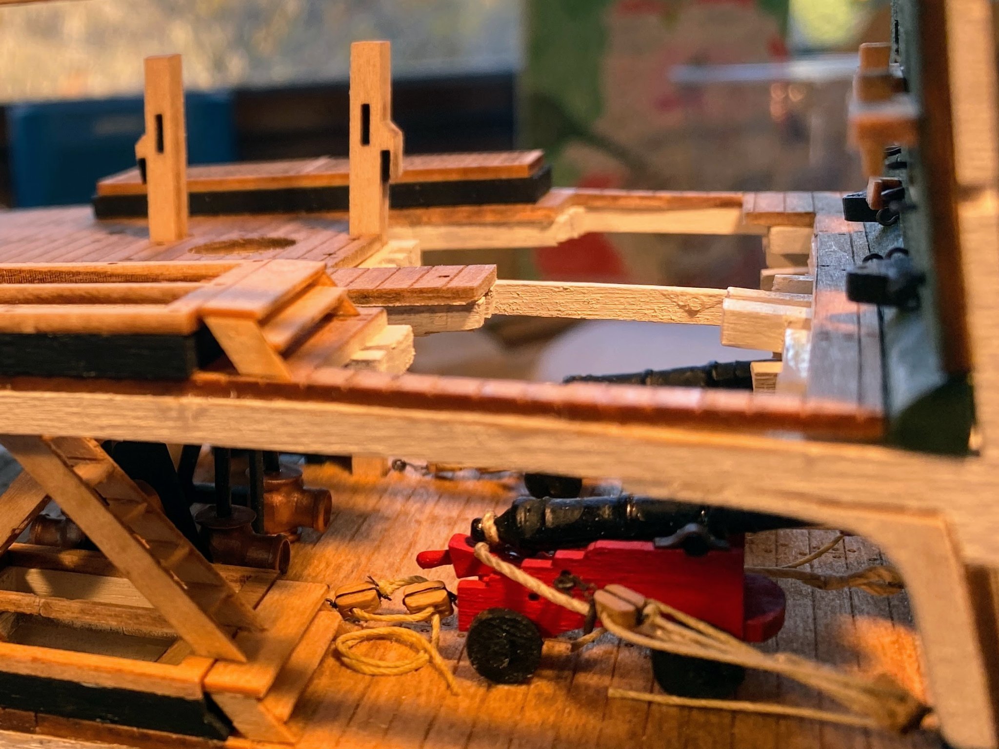
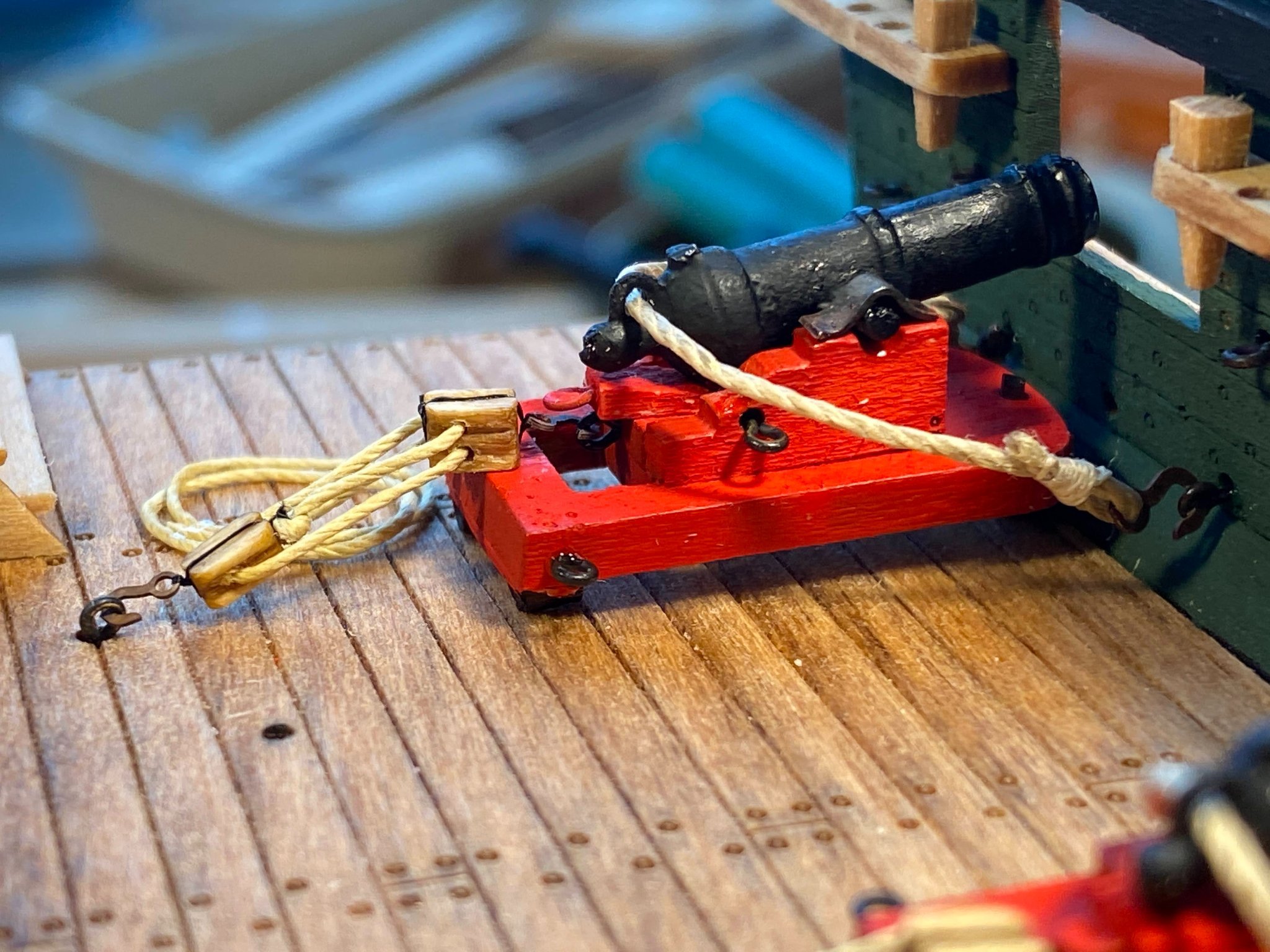
So now all four cannons are fully rigged and glued in place. First thing I did was to pull the train tackle eyebolts out of the deck and move them about 3 millimeters inboard, as far as I could given the location of the bits which extend down from the spar deck above. The blocks are still a little too close together on the inboard cannons, but it’s the best I can do. At least the old holes in the deck are pretty well hidden. Since the train tackles are pulled in fully on those cannons, the falls are longer and I made coils for them. Since by contrast the gun tackles are fully extended, I just cut the falls short. Everything just the opposite with regard to the battle ready cannons on the other side. Next I replaced the train tackle on the cannon I installed first; I think it looks better now. Note that I set things up so that on the train tackles, men would be facing the cannon while pulling it toward them, contrary to what the plans show, which would have men pulling it toward them while they faced inward, with the cannon at their backs. Somehow that just made more sense. Finally, I realized that all the breeching lines on the newer cannons are just a tad too short, meaning that the aft inboard cannon sticks out a little too far. I doubt that many will notice. Next up, knees, pumps and stairs. And something like three poles. As can be seen in the final photo above, the knees and pumps are patiently waiting . . .

- 163 replies
-
- 7
-
-
- Model Shipways
- Constitution
- (and 2 more)
-
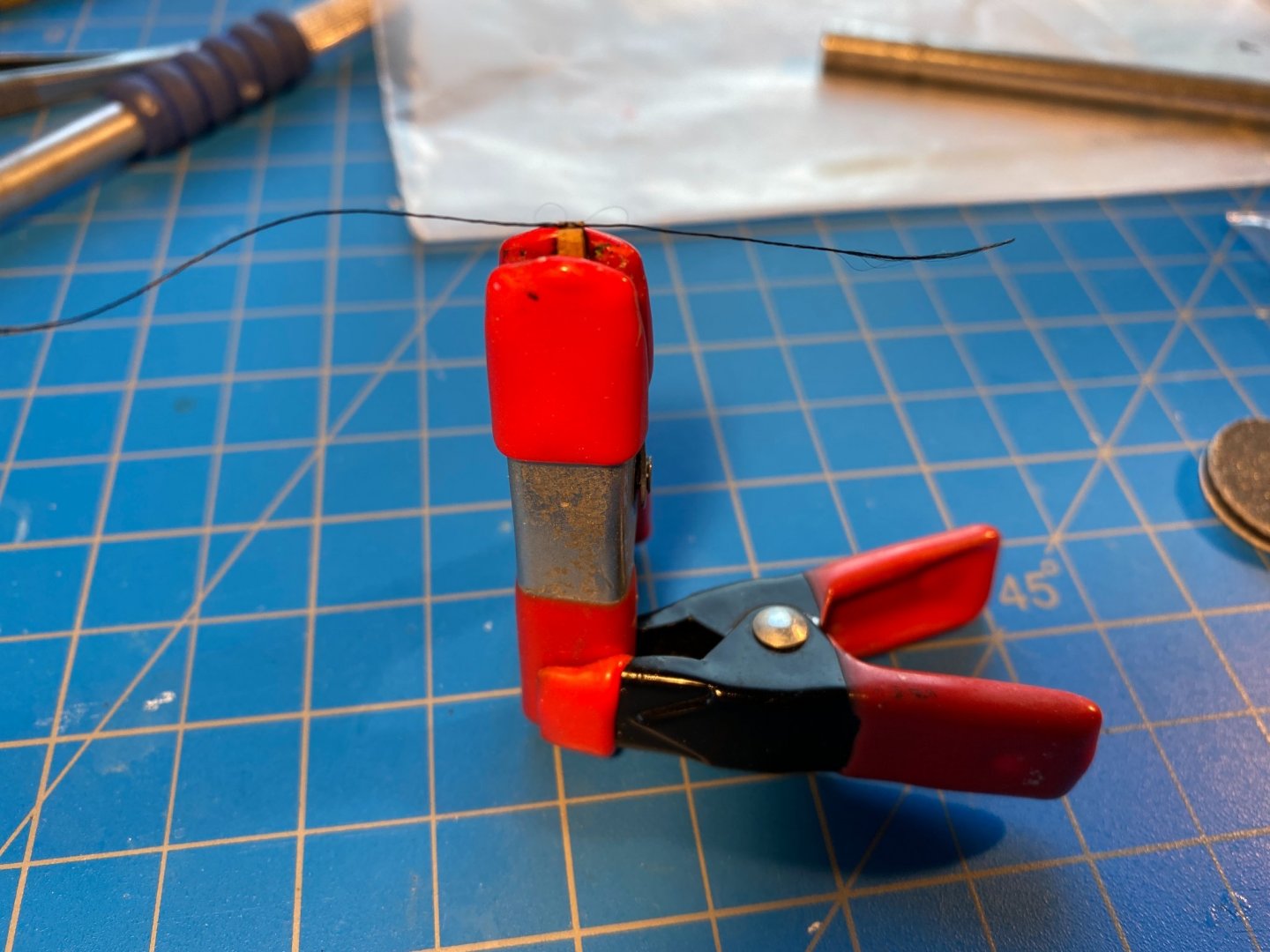
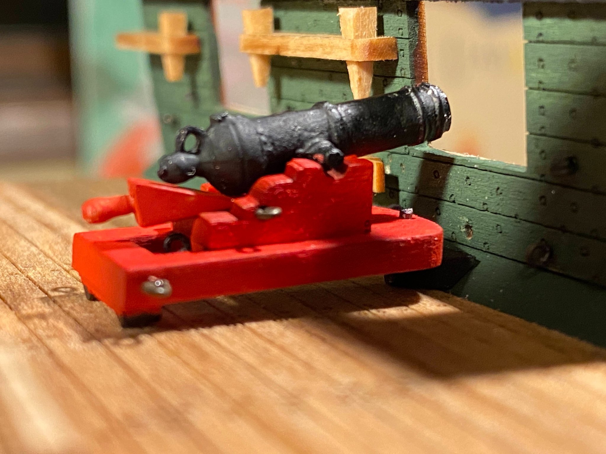
The gun deck cannons are now complete, and an important decision has been made! I learned a few things assembling and installing the first cannon, and the next three went more smoothly. I found some slightly more pliable thread for the breeching line (or maybe I was just in a glass-is-half-full mood) and whipped hooks onto either end so that the line was 3½“ long. 2 out of 3 times I remembered to slip a couple of split ring/eye bolt assemblies on to the thread first. Then as shown below, I used a mini clamp to hold the gun barrel upside down, wrapped the breaching line tightly around the protrusion at the back of the barrel, and applied a small drop of medium thickness CA. Worked like a charm. Next I bent six trammels from the supplied strip of brass, then after the photo below, trimmed them to proper length and blackened them. As I did with the first cannon, I glued the barrells to the carriage, and glued the breeching line split ring/eyebolts in place, taking care to assure that the front end of the barrels was the appropriate height. Then I glued the trammels to both the carriage and the cannon axles or trunnions. Next I rigged three train tackles, and hooked each to the eyebolt at the back of the carriage, applying a tiny drop of thin CA to where the hook meets the eyebolt. With that all done, I finally glued the quoins in place, leaving that for last since I did not want to have to try to hook the train tackles to the carriage eyebolts below the protruding quoin above. Incidently the instructions have you build a jig for holding blocks in place when rigging, a jig with two short stubs of wire, affized to the end of a piece of wood, to put through the hole(s) in the block. The "jig" I've always used is a lot easier to assemble, works with any size block, and is recycleable! 😊 I finally made the big decision (discussed several times in previous posts): I am going to cut away the spar deck and some of the framing on the starboard side (left side in the photo below) to make some of this gun deck work more visible. And I will show the cannons on that side of the gun deck in their stowed position, with the gun port lids closed. In the photo below these three cannons are dry fit in place (the first cannon is glued in, on the upper right). Some things to be addressed when these three cannons are glued in place. The breeching line for the cannon in the upper left is a little too short to allow the cannon to be pulled inboard as far as it should be. I like Bob Garcia’s “Measure once, cuss twice” advice, and I admire his restraint when it comes to the only “twice” part of it. 😊 Hopefully easily remedied by putting that cannon on the other side of the ship. Also note that I managed to dislodge one of the split ring/eyebolts on that cannon. Then there are the deck eyebolts for the train tackle, which need to be closer to the ship’s center line for the tackles to pull the cannons far enough inboard for stowage. And finally, I think I’ll try to do something about that train tackle on the first cannon. All addressed in my next post.


- 163 replies
-
- 5
-
-
-
- Model Shipways
- Constitution
- (and 2 more)


.jpg.82d1e4338df4900676786d782f8c3e03.jpg)


.jpg.ce81b16a0613c341b8bd093abb48fb2b.jpg)


.jpg.9366feb4b806c0b15e50c772b6917913.jpg)