HOLIDAY DONATION DRIVE - SUPPORT MSW - DO YOUR PART TO KEEP THIS GREAT FORUM GOING! (Only 13 donations so far - C'mon guys!)
×


ESF
-
Posts
381 -
Joined
-
Last visited
Content Type
Profiles
Forums
Gallery
Events
Everything posted by ESF
-
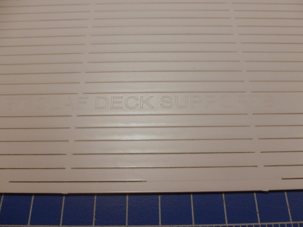
 To all those who gave likes, thank you, and a special thanks to those who are hanging in during my glacial progress. Kevin, this is only my second build and my first large plastic/fiberglass/RC kit so I'm not really qualified to judge whether it is good or not. Pluses so far are the hull fiberglass has reasonable thickness and level of detail. The gel coat is very well done and the portholes and other penetrations are located with raised tabs or molded indents to guide drilling and cutting. The kit comes with a large quantity of photos (on CD) of prototype builds; finished kits and a good set of annotated photos showing various stages of the hull and superstructure assemblies. There are two stapled sets of instructions with diagrams, text and some photos. One set is more step by step, and the other is more of a guide. The PE brass sheet appears well formed. I have only applied one PE piece so far. The RC bits were purchased after the fact, some through the manufacturer and some sourced locally. They were literally plug and play when I tested them. There is a full size drawing in color, with plan and elevation views. There are three trays of fittings with a legend sheet for each one. The superstructure and decks are laser cut plastic with different thicknesses depending upon use. Part numbers are incised into the plastic sheets for easy identification. There is a numbered list of the recommended glue/filler types (9), with the numbers keyed to the instructions. Challenges to date are that the instructions in one set don't always match the other, nor with the drawing. For instance, the waterline is described as 50 mm in one spot, but measures about 67 mm on the drawing. The description and photos in one spot show a wood built-up motor support and wood bulkheads, but the kit motor support is formed plastic and I was advised that the superstructure contains cross supports which eliminate the need for bulkheads. The starboard scupper placements near the stern were different than the port side. The only experience I have with the cast metal so far is the rudder support and the tiller arm. The rudder support seems okay. It requires sanding and drilling. The tiller arm is supplied with a small, self-tapping style screw and requires drilling out the tiller hole and the screw hole, but when I tried to turn the screw tight to clamp the tiller post the threads stripped out of the soft metal. I have ordered a new, and hopefully stronger tiller arm that comes with a set screw. Having never built a large RC ship I'm not sure what to expect in terms of a kit. This one seems quite complete but, as with any build, read all the instructions thoroughly before starting work, read them a few more times, then resolve any differences to your satisfaction before constructing carefully. Thank you Steve
- 446 replies
-
- 6
-

-
- zebulon b vance
- deans marine
- (and 3 more)
-
Carl, Just checking in for the first time. I'm sorry for your loss. I've had parents, relatives and friends pass fast and slow, and it's never easy, but I take comfort that their spirits are alive and well and with us always. Back to boats. The build looks great. I'm particularly interested in railings with separate stanchions since that will be a big part of the Vance build. Have you had any experience with a technique called heat sinking for the stanchion installation, in lieu of drilling and gluing? The kit manufacturer describes it as holding a soldering iron tip to the side of the PE stanchion, while gripping the stanchion with tweezers. Supposedly the stanchion gets hot enough to melt the plastic as you push it down. I have no idea whether it works, or if it would scorch a previously painted deck. Thank you Steve
-
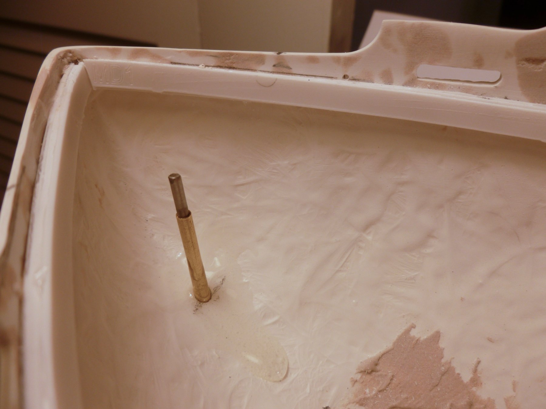
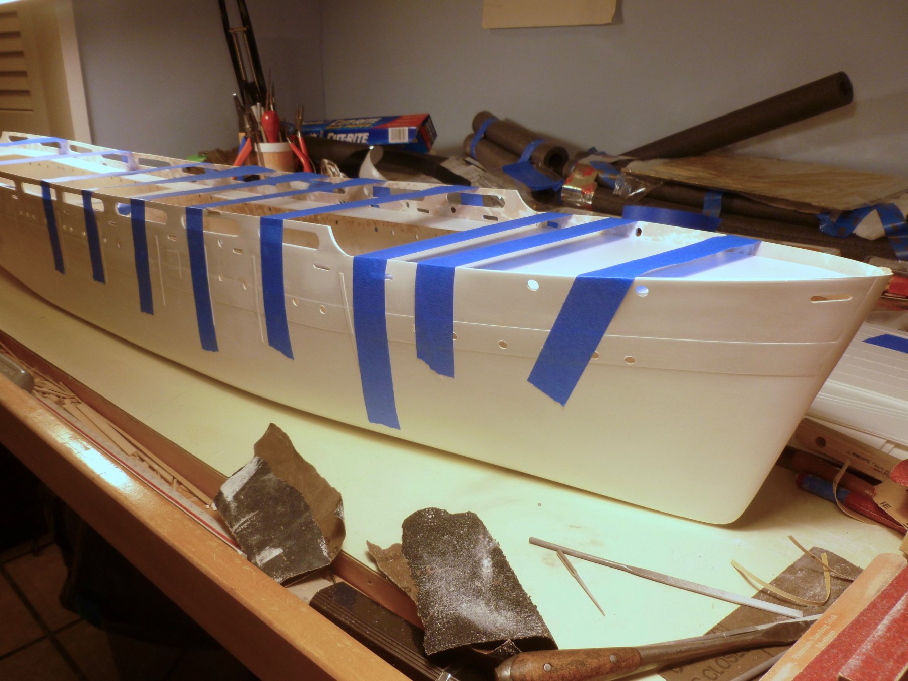
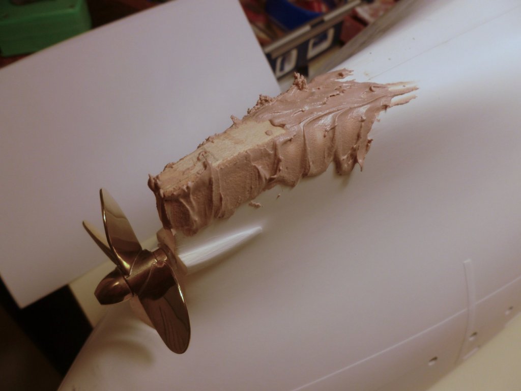
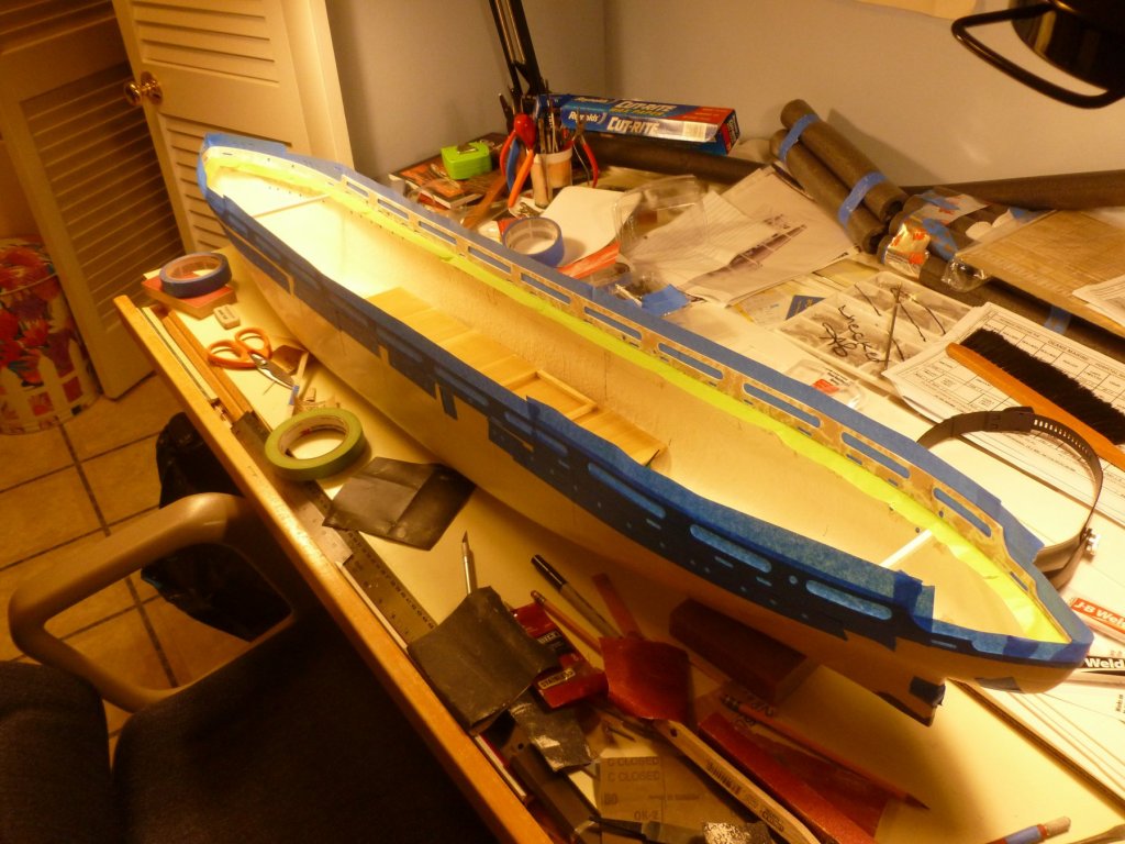
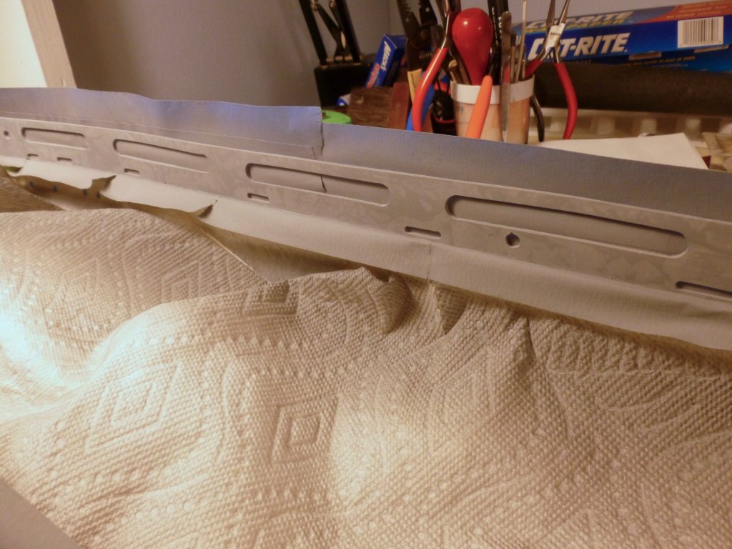
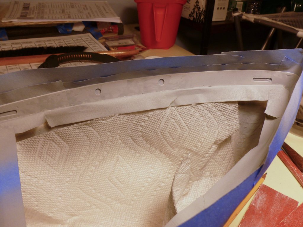
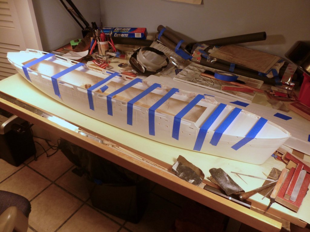
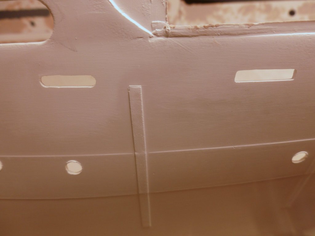
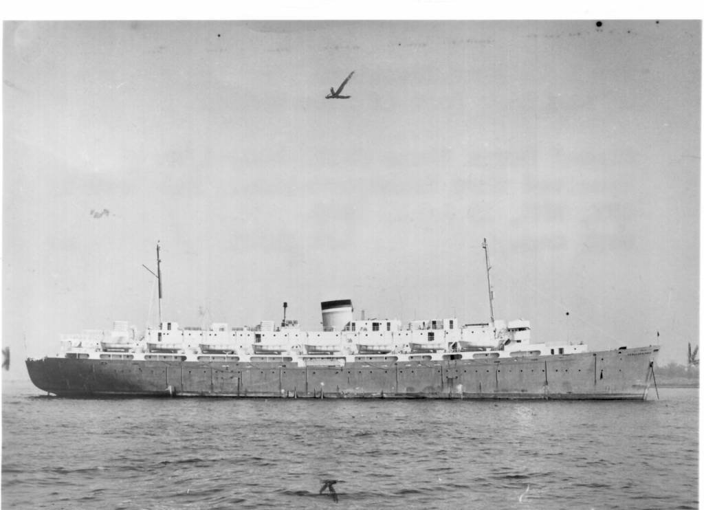
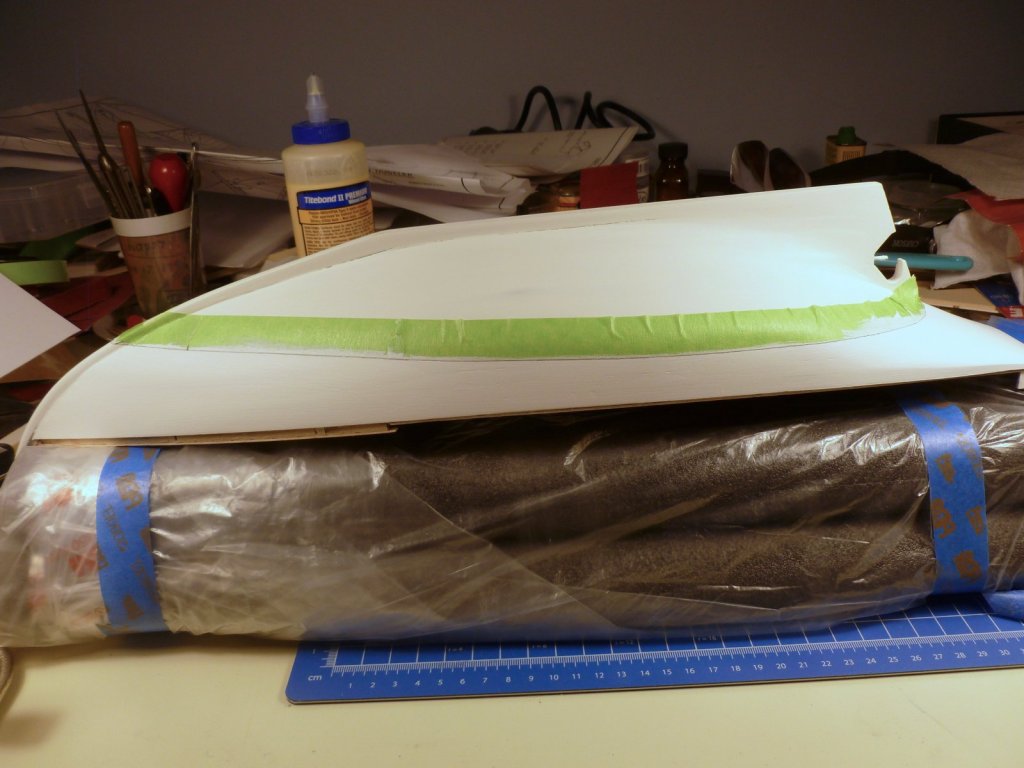
To those who gave likes, thank you and thanks for stopping by. Hal, thanks for checking in and thank you for your compliment. Steve After gluing the wood shim for the rudder support I globbed some plastic filler around it, but while waiting for it to dry I had second thoughts. Although it will be primed and painted the rudder support area will be underwater during sailing, so I sanded off the filler and replaced it with a two part cold weld reinforced epoxy. The second pic is just after placement and a full day prior to curing and sanding - I needed a bit more hardener. Given the size of the ship (54 inches) versus my Bowdoin build (23 inches) it seems like every step involves either endless repetition or long distances, rolling back and forth from one end to the other. I thought I’d give the bulwark interior a shot of primer. I want to paint it prior to placing the main deck to keep the joint clean between the two. After three laps of the ship, yards of masking and a wipe down with tacky cloth it was ready. The slight blotchiness is the bulwark filler showing through the light primer coat. I’ll prime again after filling a few defects. Hopefully it's not bleed-through. If it is I'll go back to Kilz or BIN. The paper towels are just to keep paint off the electronics/battery deck which was just sealed, and the prop tube/motor mount/rudder area. A question is what should be the finish color of the inside of the bulwark? In the National Archives photo above the promenade openings are white on the outside, probably leftover from the Vance’s hospital duty, but the hull and exterior of the bulwark forward and aft are darker, which I am assuming is a gray tone (Battleship Gray in Krylon speak) added to cover up the large crosses and green horizontal stripe that signified hospital use. If the forward and aft bulwark interior was white during hospital work is it reasonable to assume it would have been painted over when the exterior bulwark and hull were refinished? Or should I assume only the hull exterior would have received the new paint since the refit only lasted a month?


- 446 replies
-
- 13
-
-
- zebulon b vance
- deans marine
- (and 3 more)
-
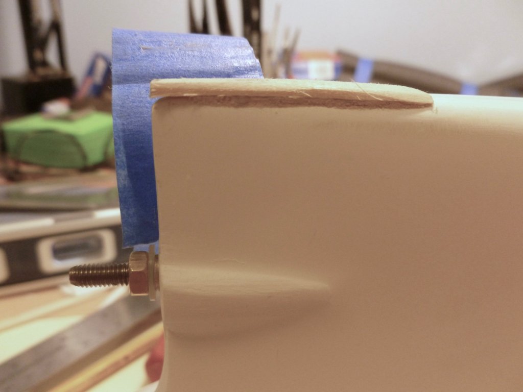
To all who gave likes, thank you and thanks for stopping by. Lou, thanks for your observation. The rudder support was loosely taped in the pic but when I tightened it up it did help the clearance. Steve I CA’d a wood shim to the hull bottom and did some preliminary sanding. Then I taped the rudder support to the shim and worked on the layout of the rudder tube hole through the hull. Voila, it worked and the prop just clears the support. No need to replace it or try to fabricate a new support. I’ll do a little more sanding at the support fillet, then work to make the installation permanent. At the interior I sealed the tube to the hull with epoxy and will follow it with some structural support. All in all a better finish to the day than it started out.

- 446 replies
-
- 9
-
-
- zebulon b vance
- deans marine
- (and 3 more)
-
To those who gave likes, thank you and thanks for stopping by. Kevin, thank you for the links and suggestions. I realized that if I pack the hull bottom 1.5 mm in the area of the rudder support, it will move the support down far enough, that with some judicious sanding of the support it will clear the propeller. We'll see when executed but for now it looks like problem solved!
- 446 replies
-
- 6
-
-
- zebulon b vance
- deans marine
- (and 3 more)
-
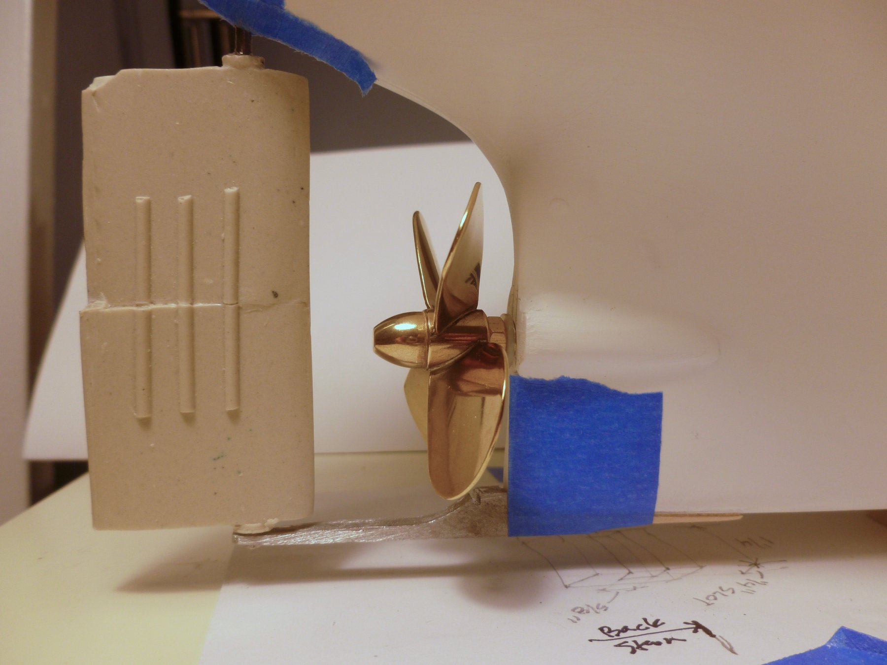
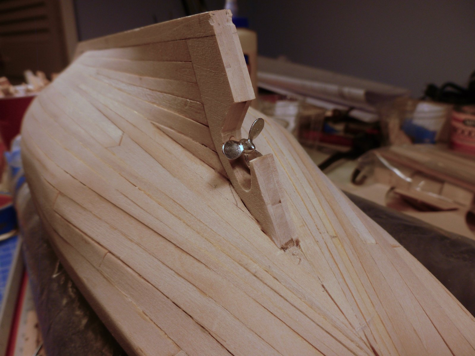
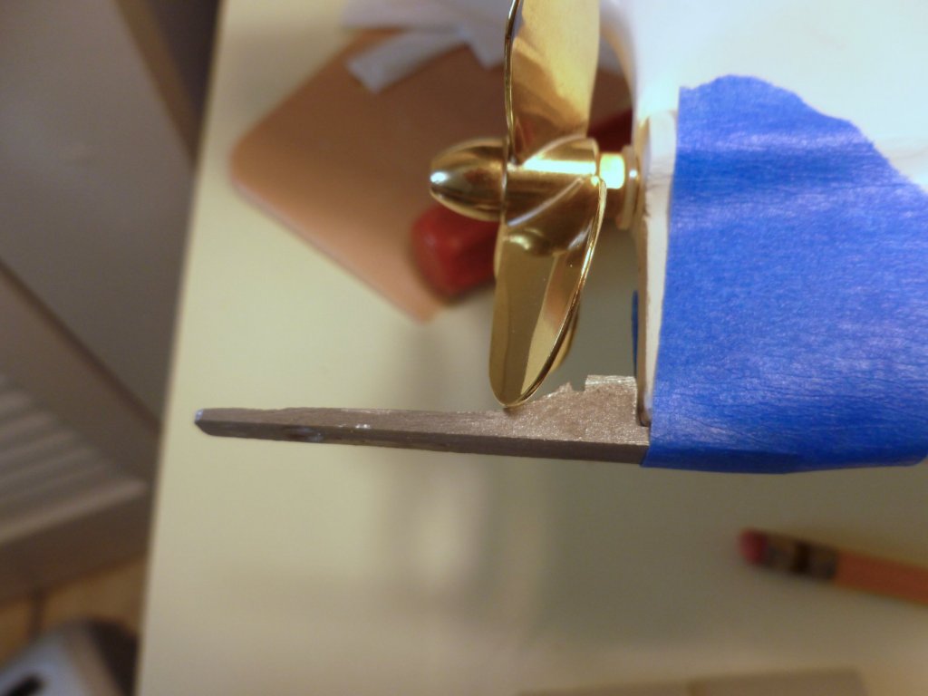
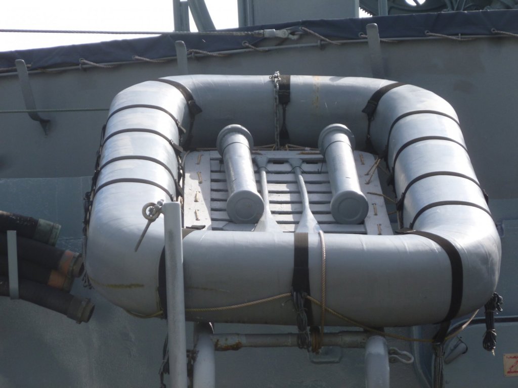
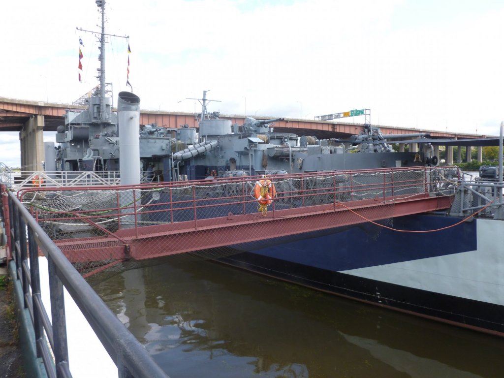
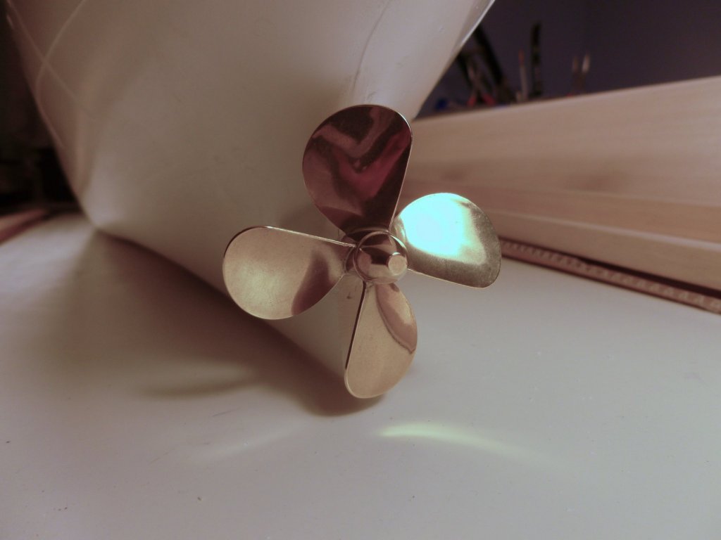
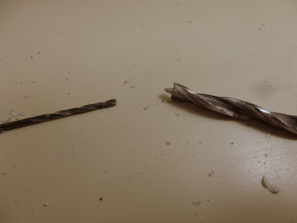
To all who gave likes, thank you and thanks for stopping by. Steve I visited the USS Slater museum (https://www.ussslater.org ) near us to see if I could find inspiration for the correct gray paint on the hull, and to check out a few details. While I was chatting with the volunteers who do a great job of maintaining the Slater, I mentioned the Vance and said I was trying to determine which was the correct gray paint. One of the fellows said “Just pick one! Even on the same ship the grays could be different in different areas, depending upon who mixed which batch of paint.” Of course they also went to great effort to get the historically correct dazzle colors and pattern when they repainted the Slater a year or so ago. I was laying out the rudder and rudder support when I discovered the support fouls the propeller. At first I thought I could cut away most of the fillet in the support, but quickly realized that the prop also fouls the bar of the support. I rechecked the instructions and the prop shaft is exactly where it was shown to be, centered on the prop shaft fairing. An obvious fix is to install a smaller prop but I don’t know how that will impact the operation. I sent a note to England and will see what they have to say. In the meantime I thought I might modify a stainless steel angle bracket, but after getting a new carbide bit for the Dremel all I did was spray myself with tiny hot bits of metal, with virtually no progress in the attempt to cut the bracket down the middle. Brass would be easier to work, but in the end I'd rather not have the support extending down below the hull. If anyone has a suggestion which would allow keeping the current prop, other than ripping out the entire driveline and motor support which are epoxied and Bondoed in place, please chime in. Thanks.

- 446 replies
-
- 7
-
-
- zebulon b vance
- deans marine
- (and 3 more)
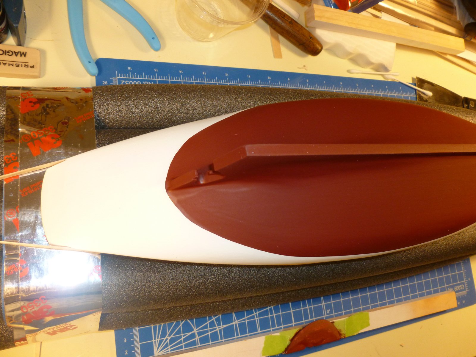
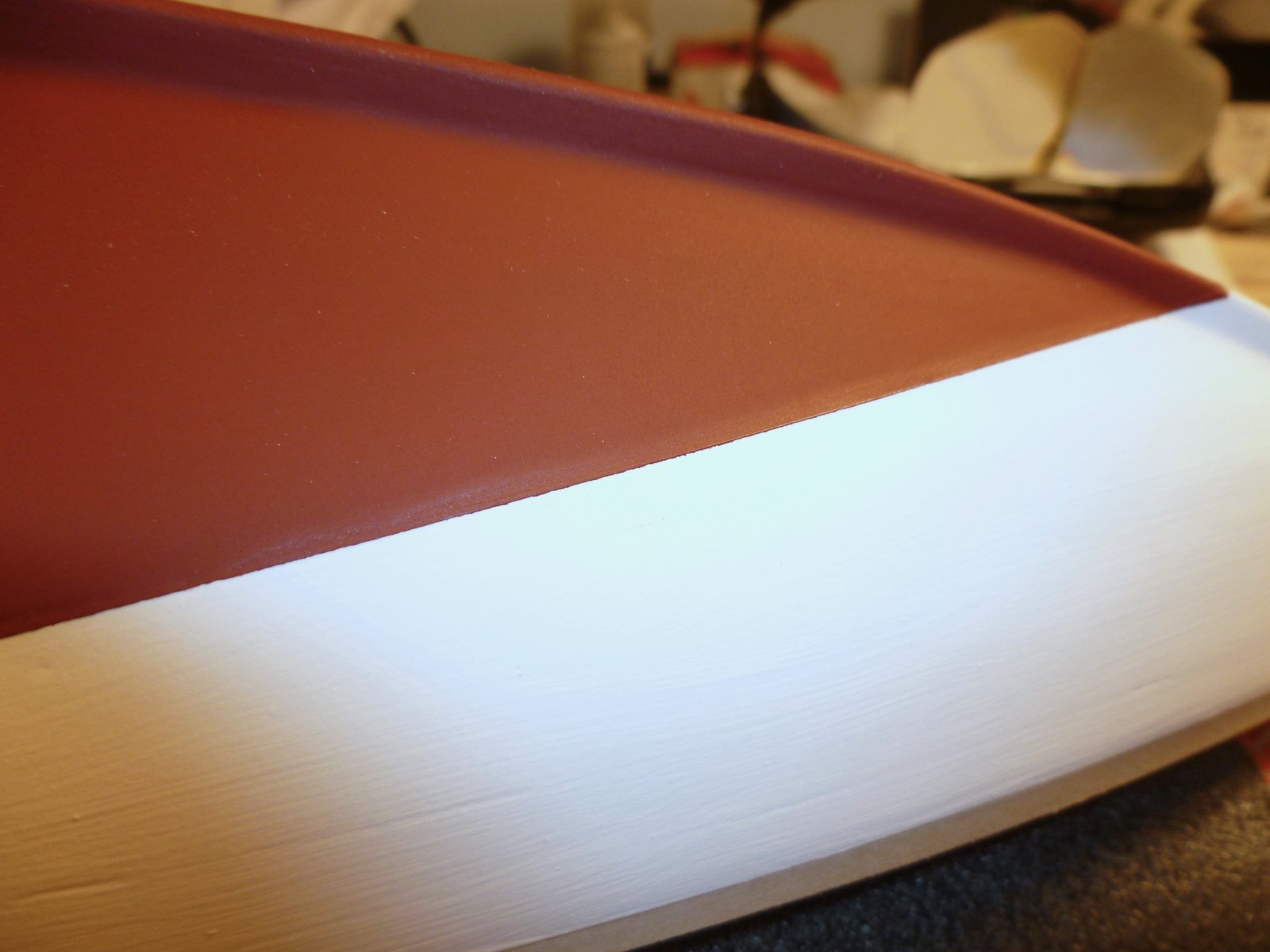
-
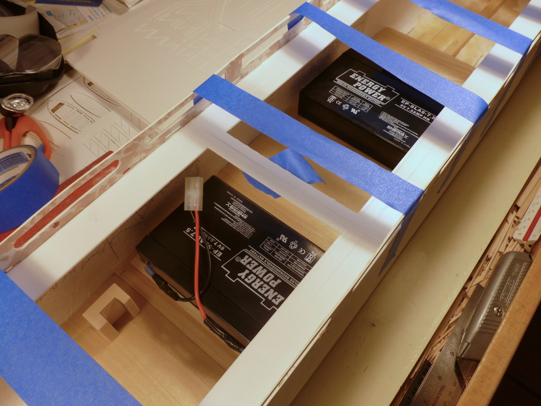
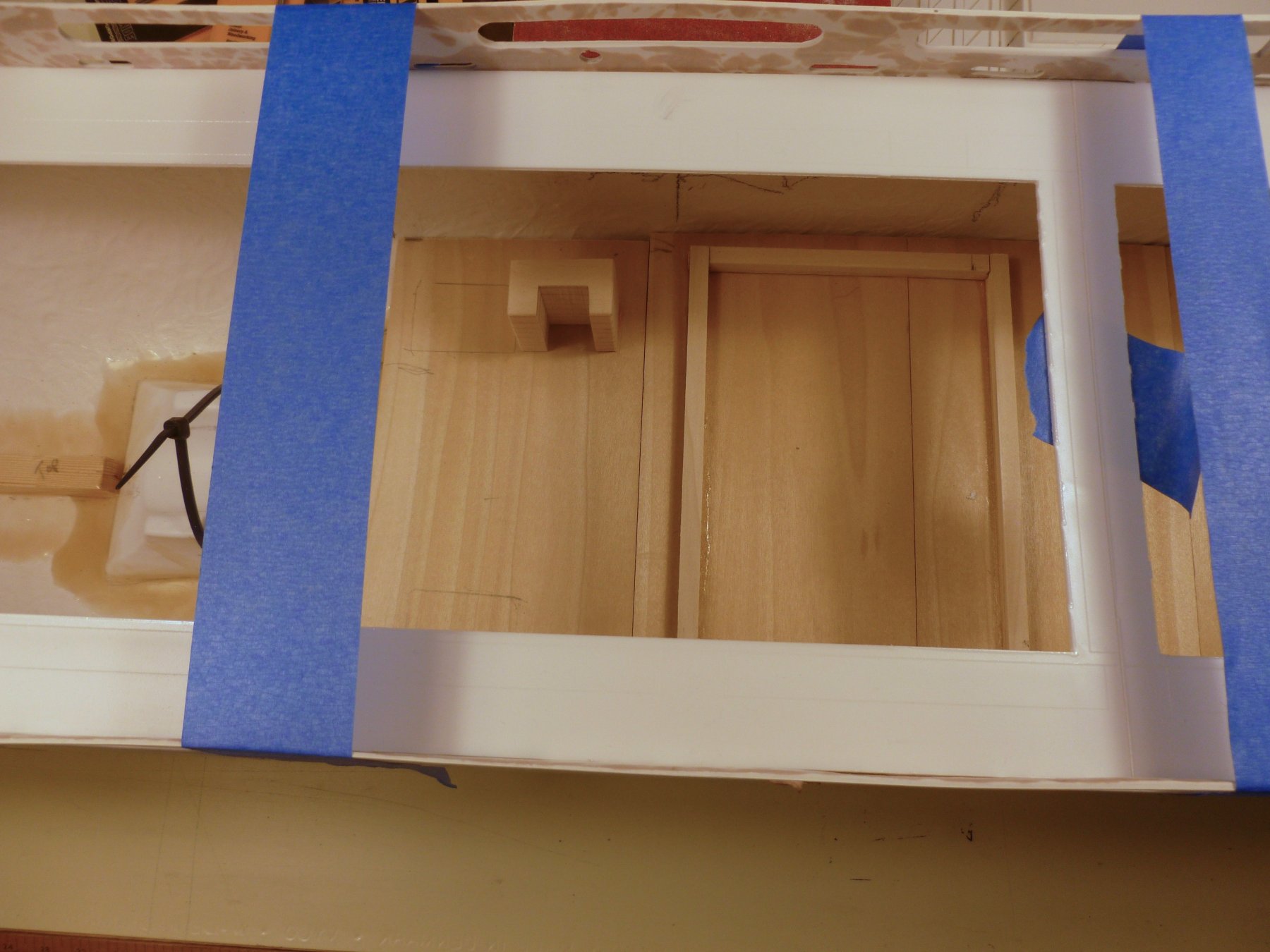
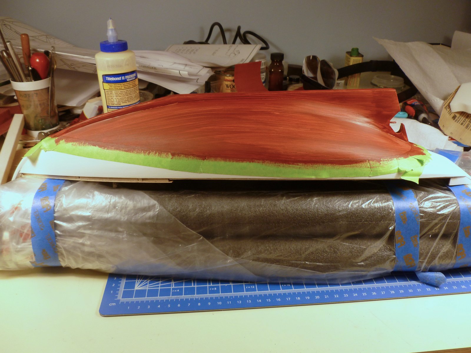
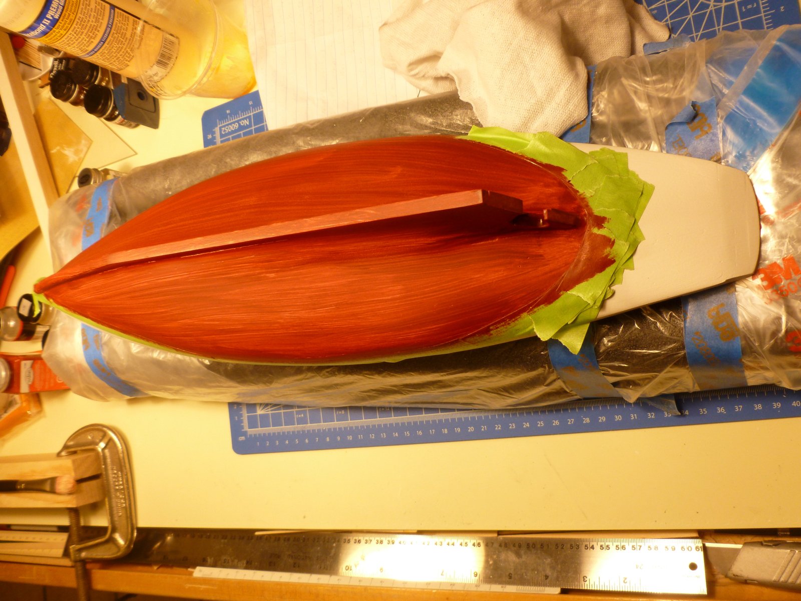
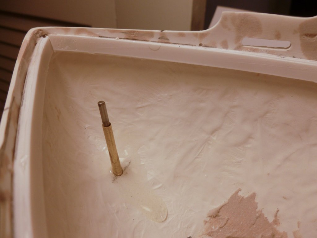
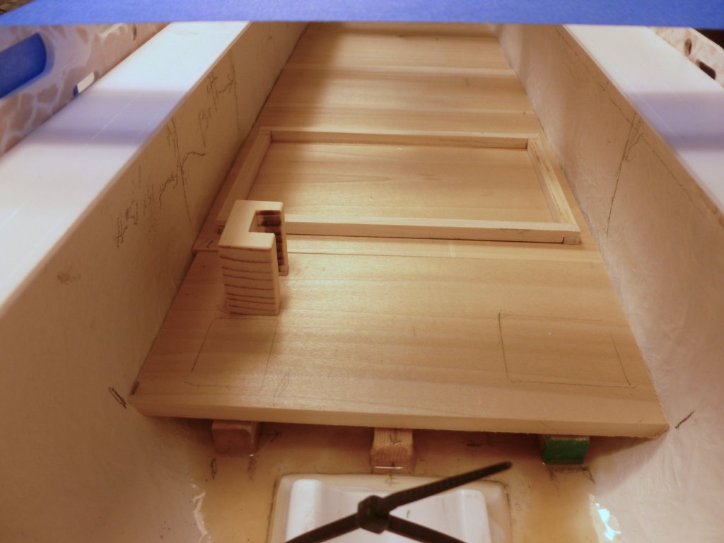
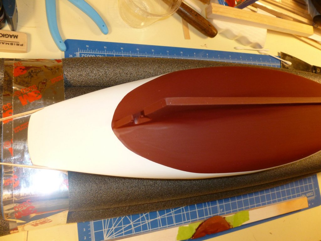
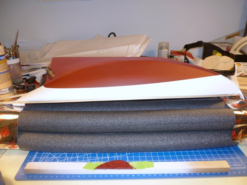
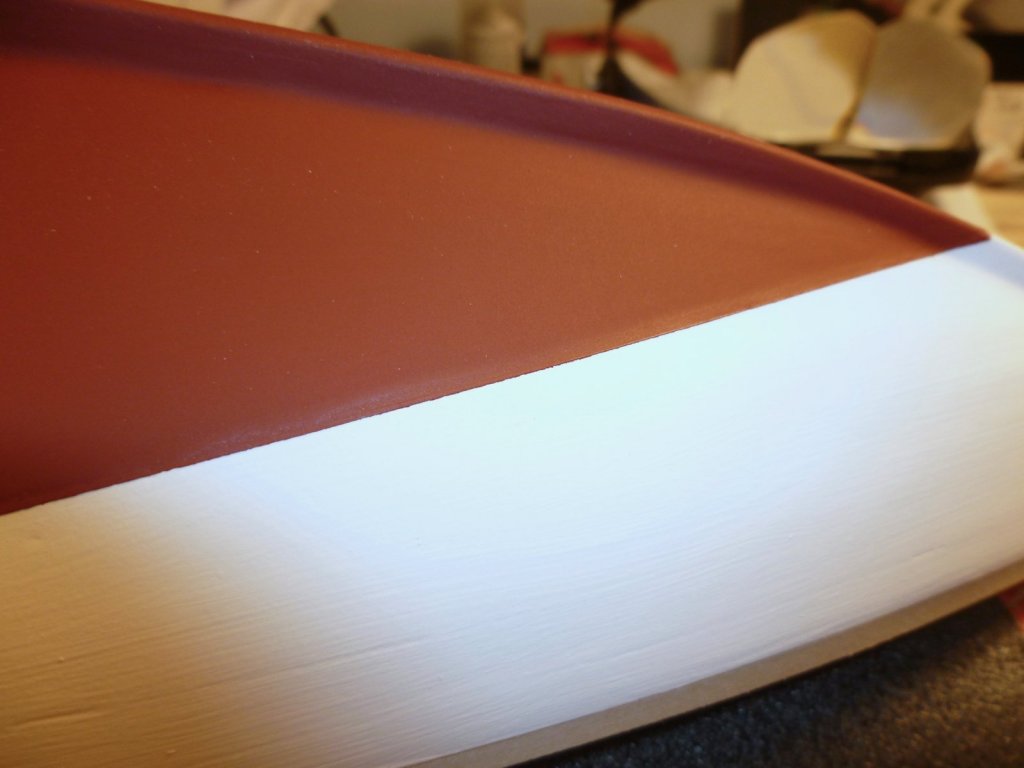
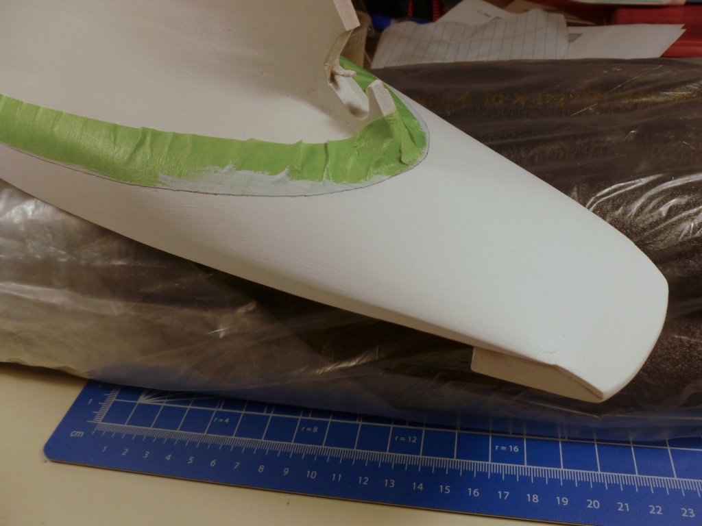
To all who gave likes, thank you and thanks for stopping by. Carl, thanks for your ongoing interest and your suggestions. It was no fault of the tool or bit, other than it is old and the on-off switch is on the wrong end when you need it in a hurry. Steve I sealed the prop tube with epoxy at the hull penetration and then gave it structural support with Bondo. For the rudder (yet to come) the instructions show a wood block in Bondo with the rudder tube drilled through it but I think I want to start with an epoxy seal there too. Looking toward the bow, the electronics deck is installed, along with a crib for the battery, and a support block for the on-off switch. The layout marks are for the RC receiver (port) and electronic speed control (starboard). I cut the two pieces of main deck from the laser sheet and test fit them to ensure there is access to the electronics. The main deck has two sizable openings and parts of the superstructure are to be installed loose to allow access. Apart from snagging the blue tape on the in-out the batteries were an easy fit. The forward battery is primarily for ballast and I need to make a little crib for that too. I may put some velcro on the batteries and e-bits to help hold them in place. I made a test paint sample of the two hull colors (slate gray and deep red) but the red is not deep enough and the gray is okay but could be more cool (blue-gray) in tone I think. I’ll have to try again. The challenge is that there is a lot to paint. I don’t have an airbrush (yet?) and it’s too much to brush paint so I’m limited to what is available in rattle cans.


- 446 replies
-
- 8
-
-
- zebulon b vance
- deans marine
- (and 3 more)
-
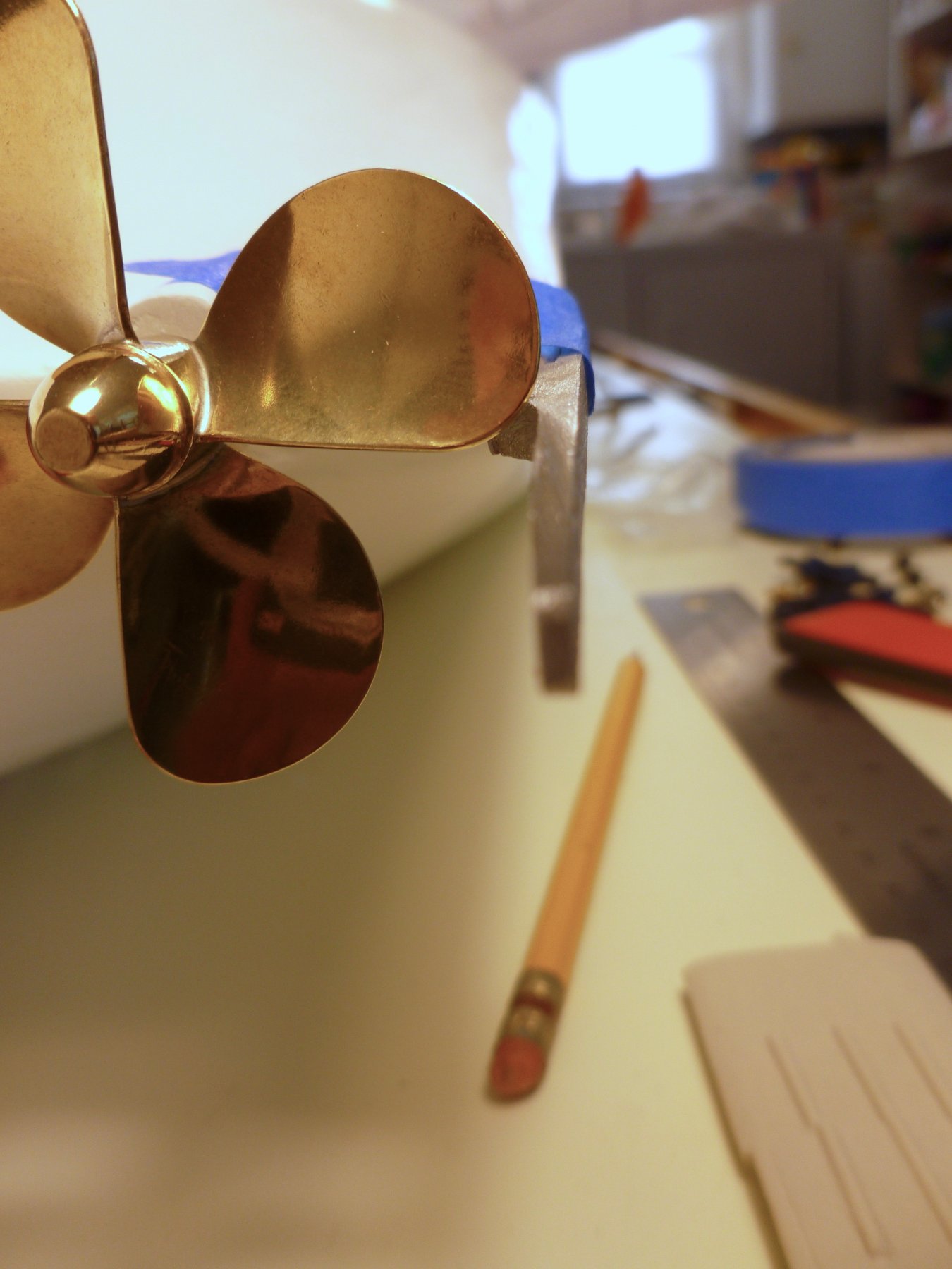
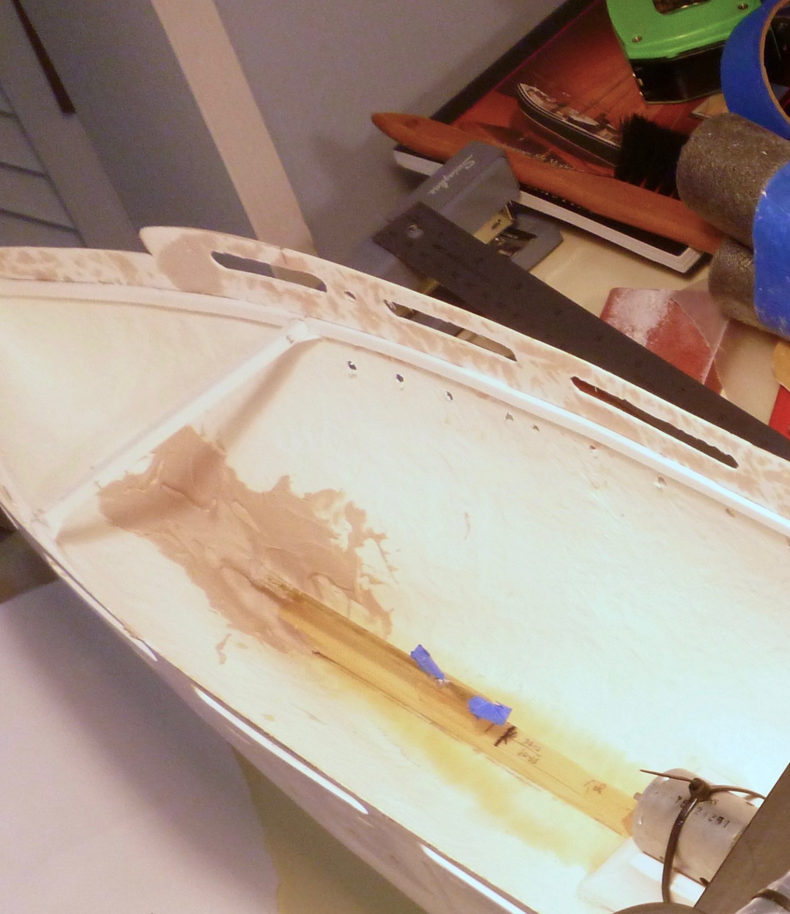
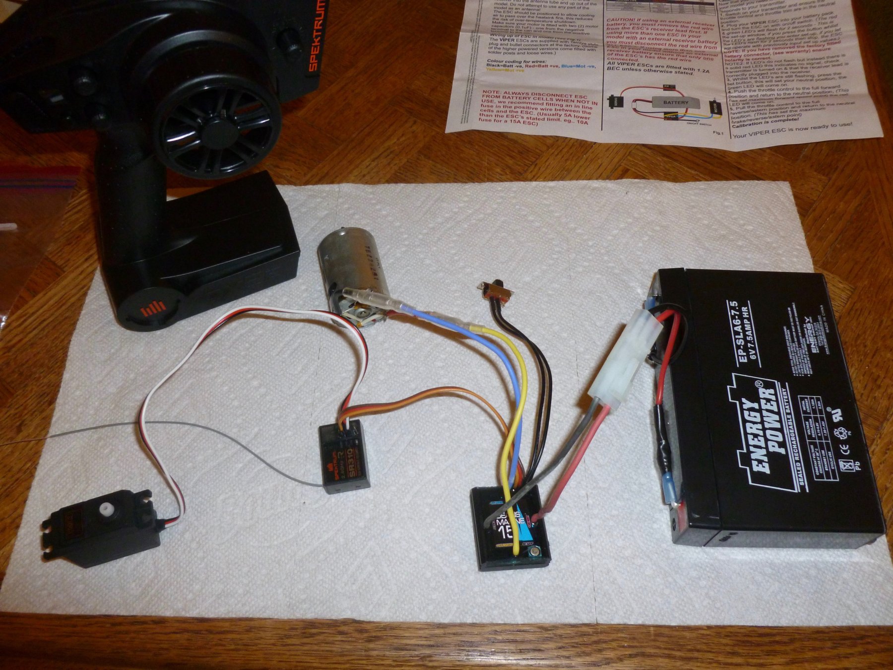
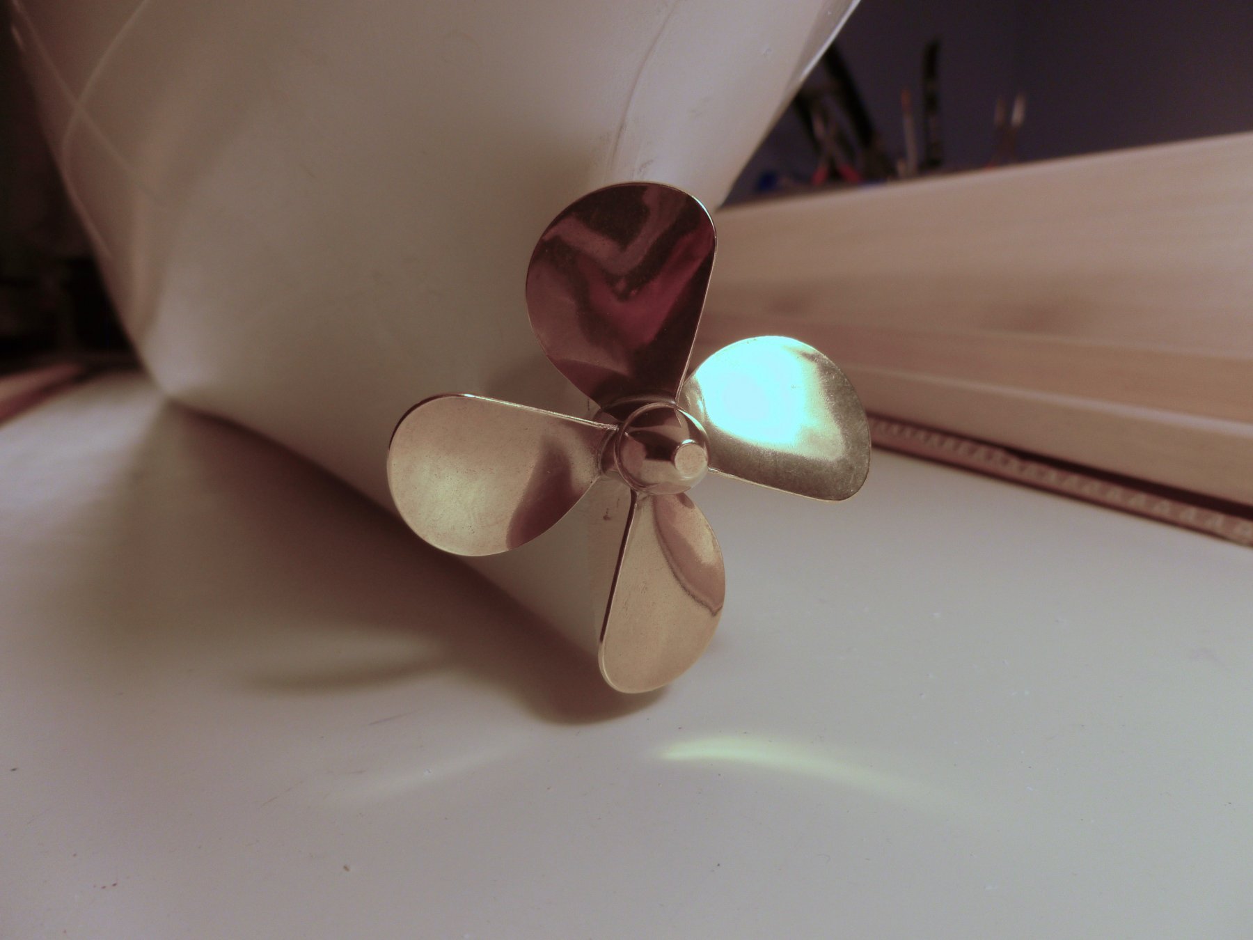
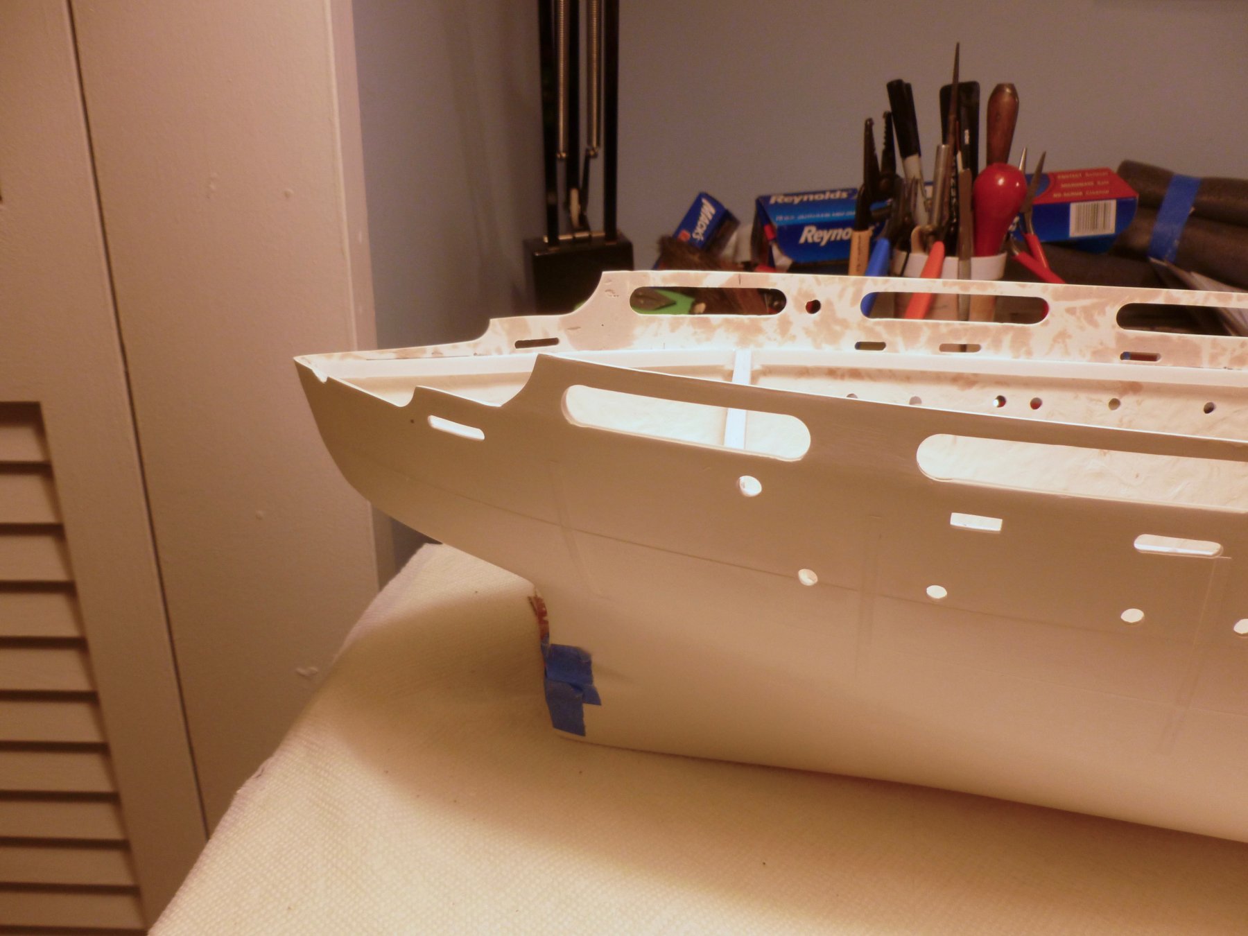
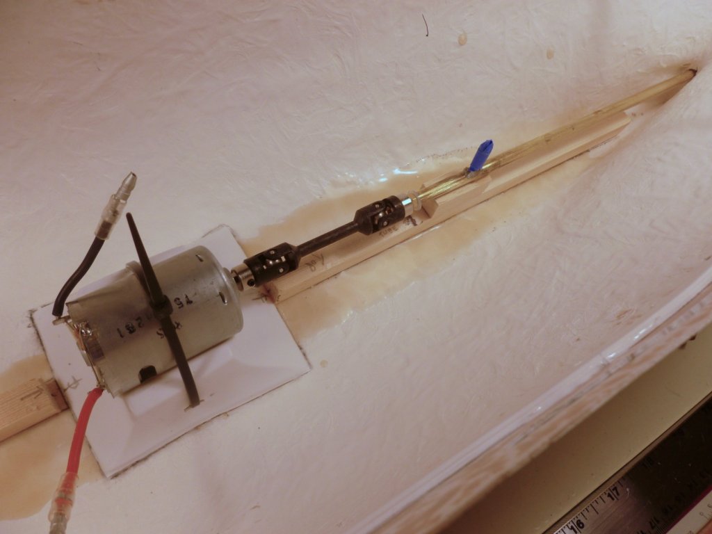
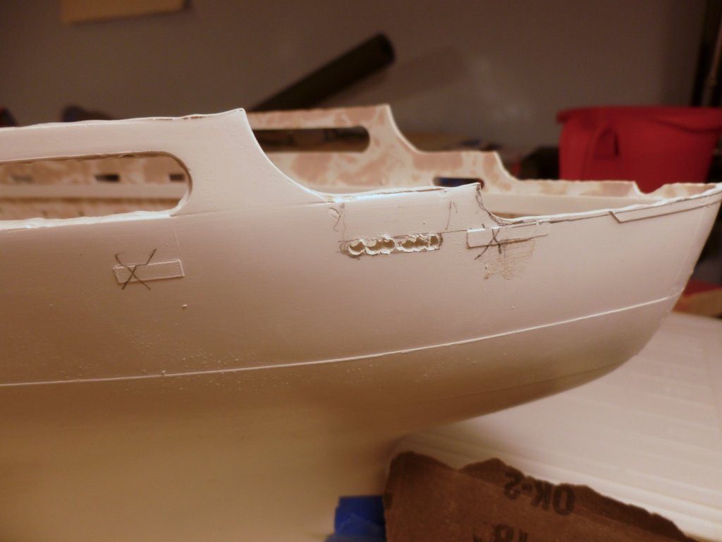
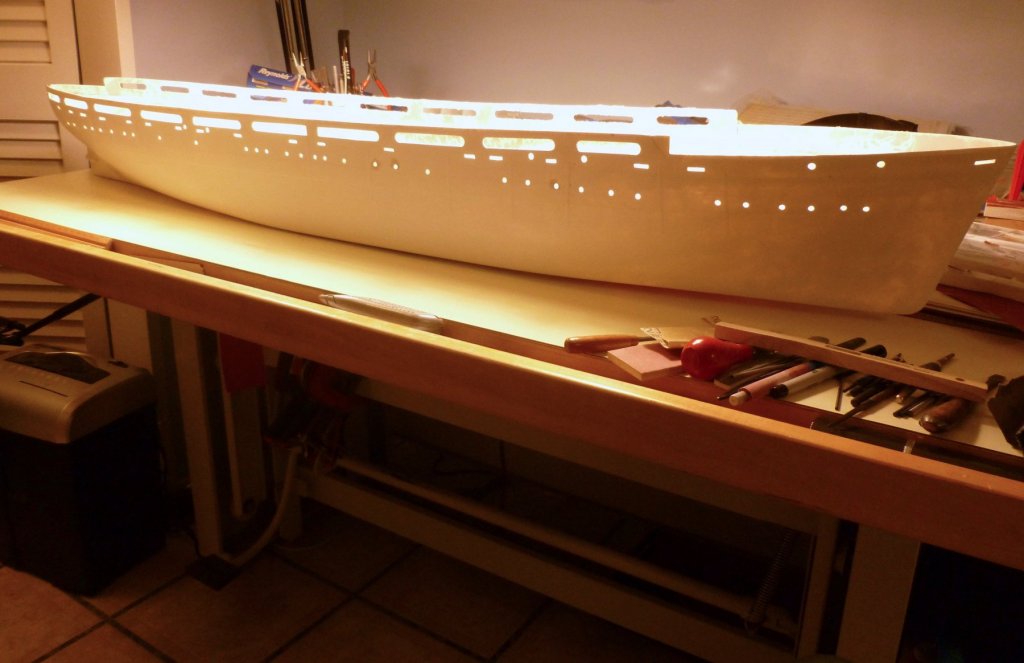
To all who gave likes, thank you and thanks for stopping by. Steve Much of the work has been focused on cutting out the remaining portholes, all the promenade openings and the remaining scuppers (freeing ports). The scuppers have rectangular locating tabs moulded into the hull but after chain drilling and filing each one I discovered from photos that the Vance’s are rounded at each end (stadium shape in math-speak). So I made another lap of the ship to round them all out. At the port stern area the scupper tabs were mis-located and too many, relative to the starboard layout, requiring them to be sanded away in favor of a new position. The hull bulwark top edge ends in a thick mould flash. It proved quite resistant to sanding even with 60 grit in an electric palm sander, so I tried a side cutting bit in a Dremel. That worked, all too well as evidenced by a nice gouge in the bulwark at the initial touch. The remainder was trimmed very, very carefully without incident, until the very last cut at the stern when the bit grabbed the fiberglass as I was cutting down the bulwark to roughly the required profile, biting a chunk out of it. Bondo, Bondo where art thou. Since the ship will be powered a platform for the electronics must be constructed. The first step is bonding wood strips to the hull on either side of the keel using fiberglass resin. The patio blocks came into play again to keep things flat while the resin cures. The motor, universal joint, propeller tube, propeller shaft and propeller were test fitted. The working propeller is a pretty brass piece (the kit version is a rough metal casting) in a size and shape as recommended by the kit manufacturer. RC electronics are all new to me. Compounding it is that some of the parts came from the kit manufacturer, but the transmitter, receiver, battery and charger were locally sourced from an RC race car shop, a battery store and an auto parts shop. For those unfamiliar with RC the parts in this build are the motor (duh), an electronic speed control (ESC), a servo to operate the rudder, a receiver with small antenna to get the signals from the remote 2 channel transmitter, an on-off switch and a 6 volt 7 amp hour gel-type battery similar to that used in a child’s power wheels toy car. At the suggestion of the manufacturer I bought a second battery, for backup and as ballast. The only extra wiring is a small harness to make up the gap between the Tamiya connector on the power wires from the ESC and the spade connectors on the battery. I was expecting a lot of fettling but when I flipped the switch and turned on the transmitter the parts had a brief flashing conversation amongst themselves and went to work. No fuss, no muss. I’ll end here for now so I don’t push my luck.

- 446 replies
-
- 8
-
-
- zebulon b vance
- deans marine
- (and 3 more)
-
Chris: Thanks for stopping by and for your kind comment. Dean's Marine in England is the manufacturer and vendor of the kit. The link is below. https://www.deansmarine.co.uk/ I'm not sure if this will work as a hot link but if not it could be cut and pasted. The kit is the St. Olaf in their merchant ship section. Steve
- 446 replies
-
- 3
-
-
- zebulon b vance
- deans marine
- (and 3 more)
-
To all who liked, thanks for stopping in. I appreciate your interest. Carl, I've gone to the darkside (white styrene side?) for awhile, but for a good cause. And this one will actually sail (he said hopefully). My grandson has already made a Lego figure of my late mother (complete with dress) to stand on the Vance when she takes her ceremonial trip across the pond. The other part of me also researched my next wood model, for which I have procured some plans and which I hope will start in a year or so. Thanks for the Glue 'n Glaze tip. I'll check it out. More work to show later. Steve
- 446 replies
-
- 5
-
-
- zebulon b vance
- deans marine
- (and 3 more)
-
Moab, thanks for stopping in and for your compliments. I've become a fan of jigs and I'm glad you could make use of them. Steve
-
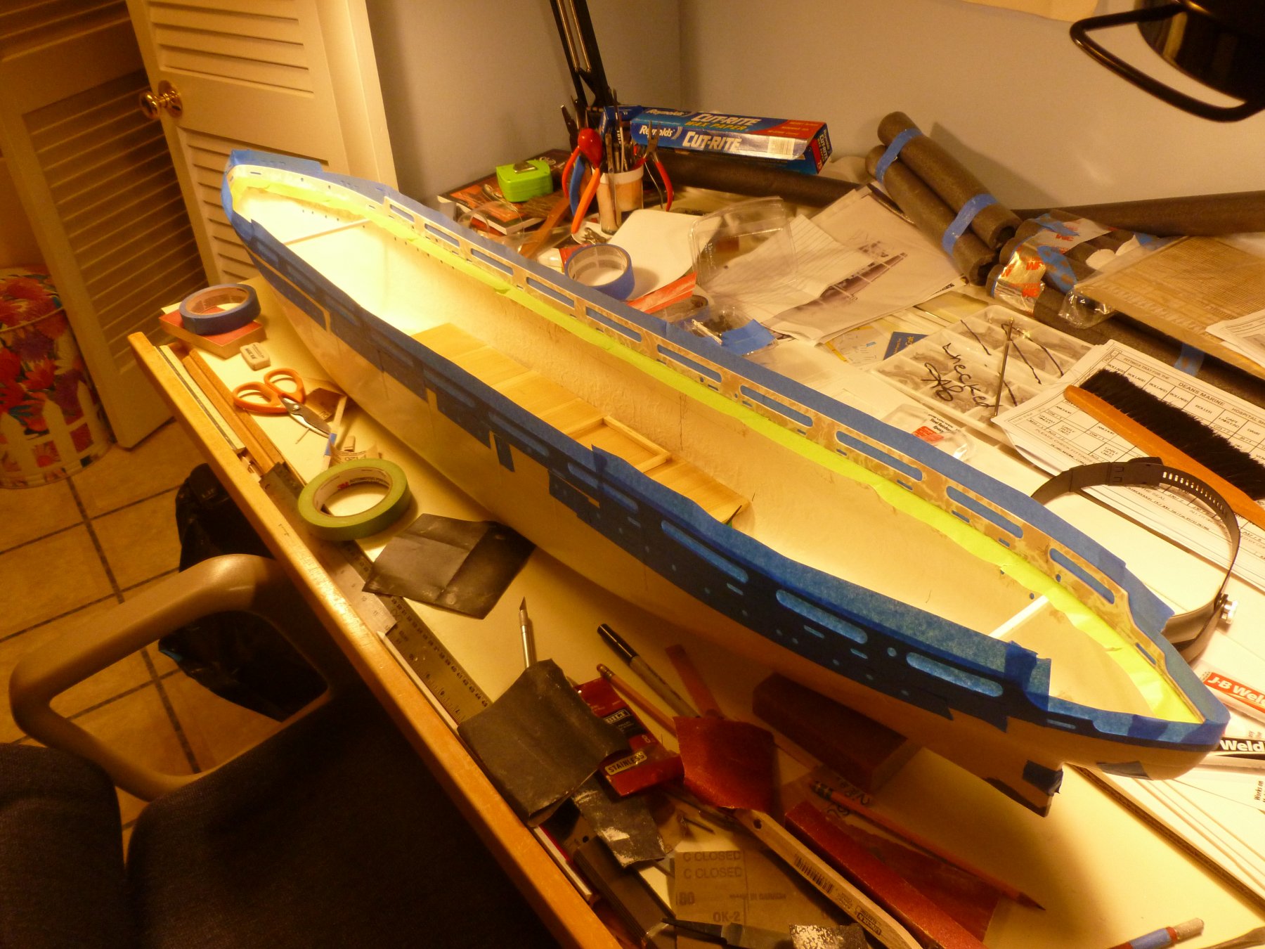
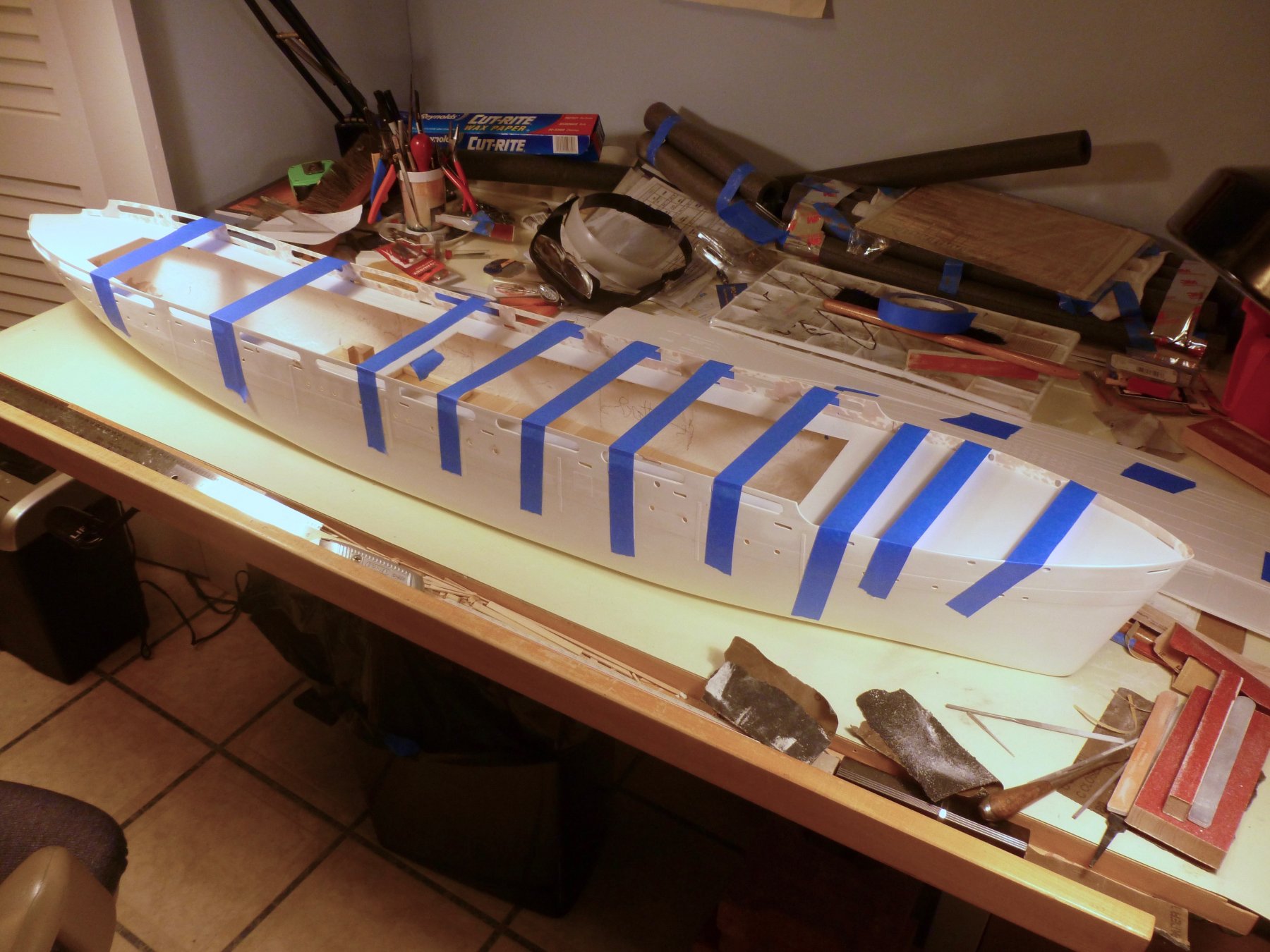
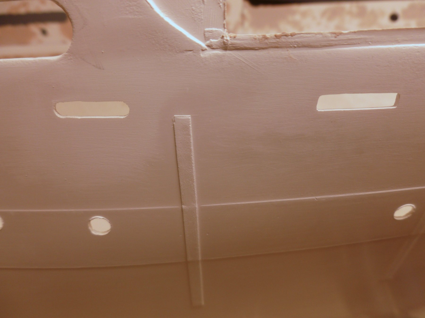
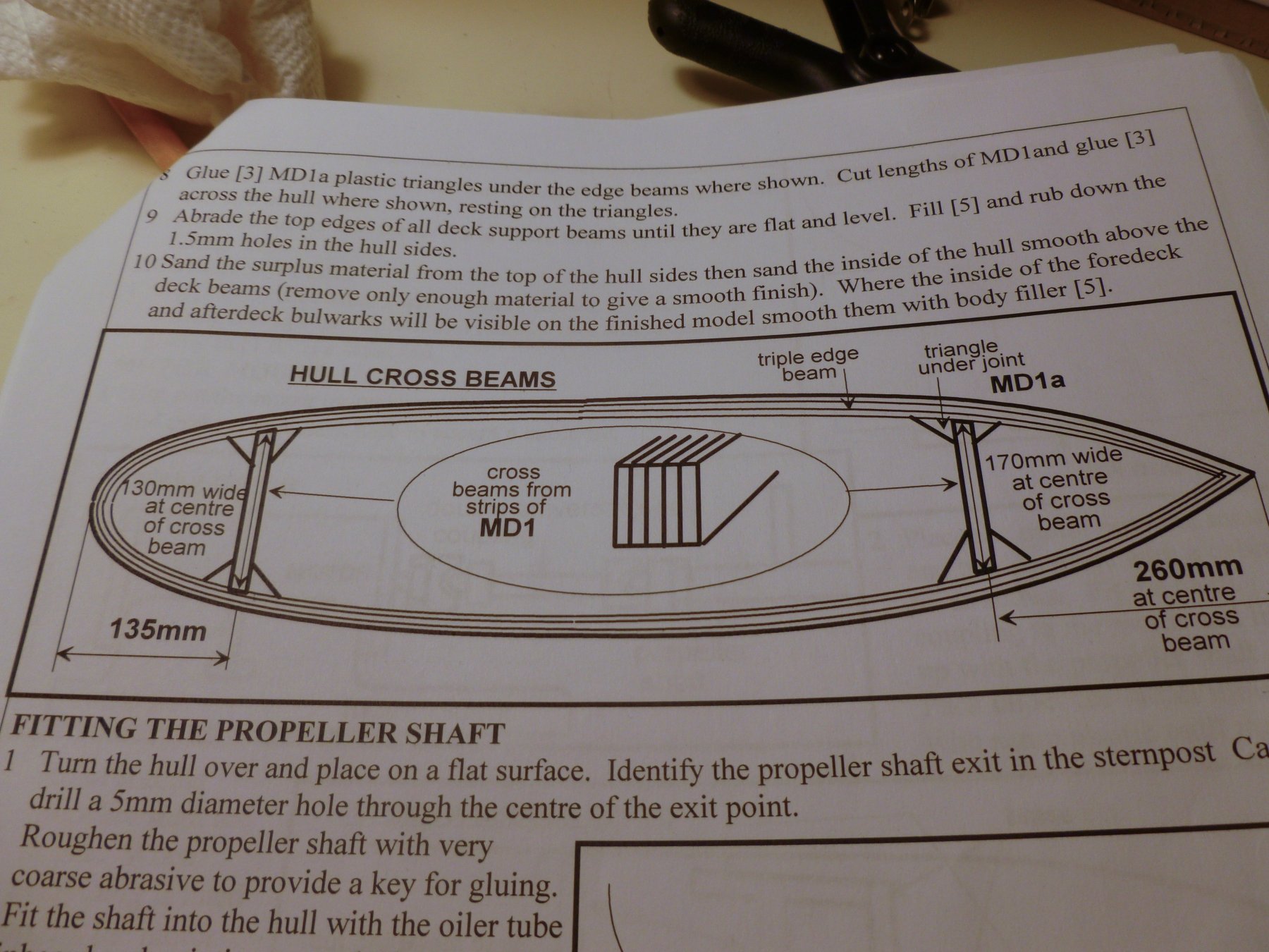
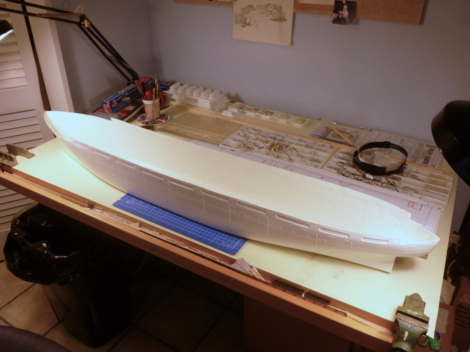
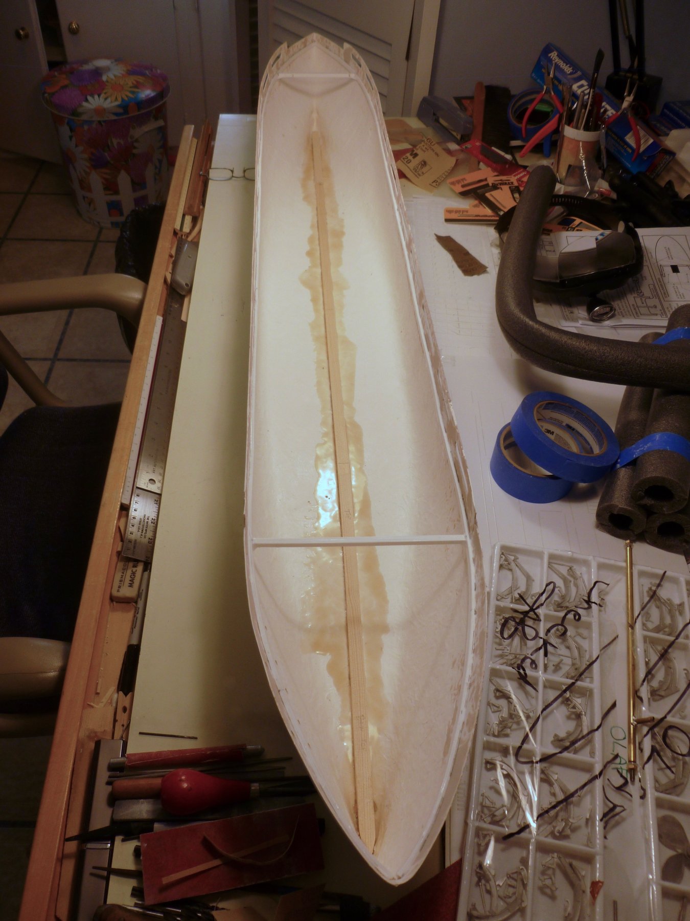
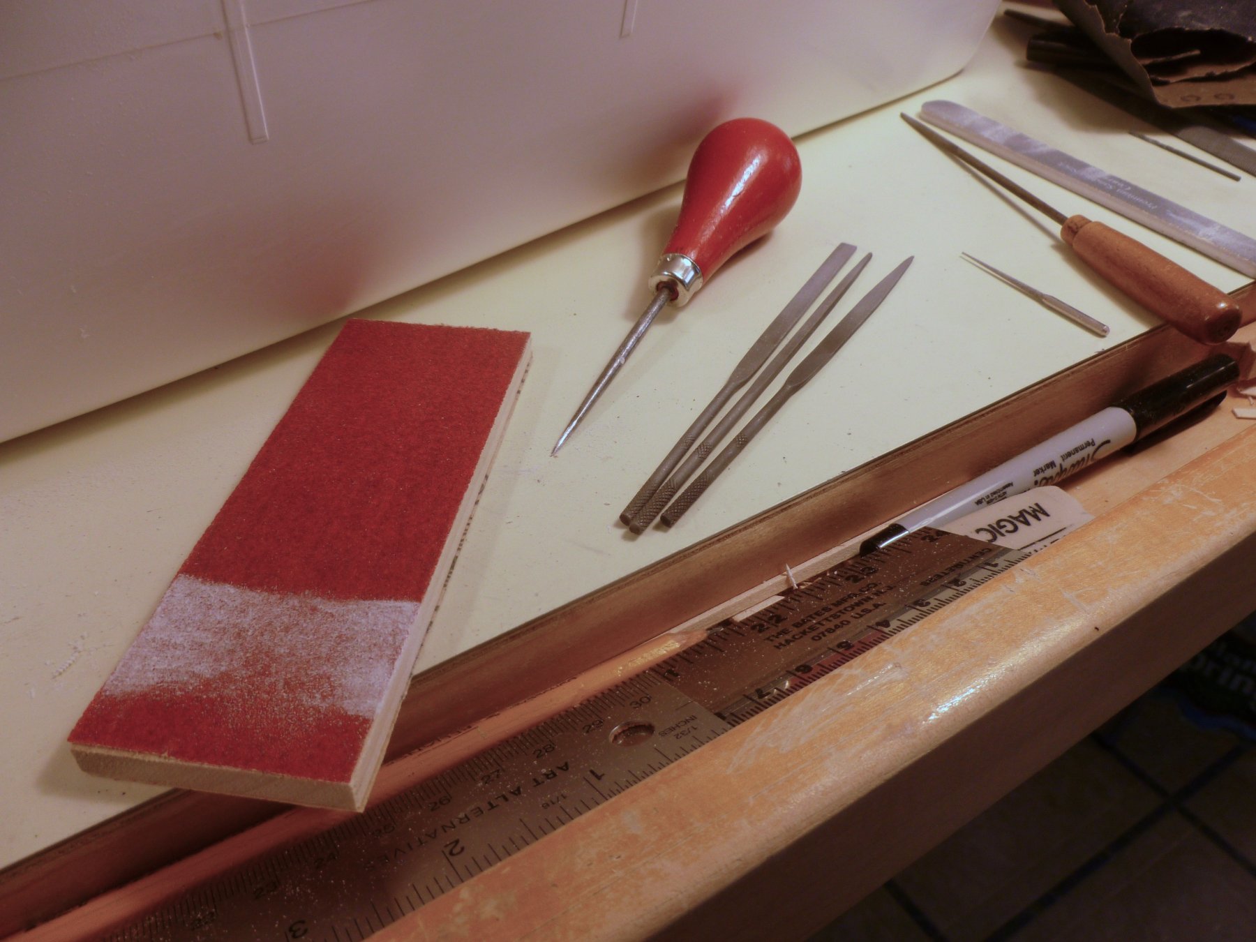
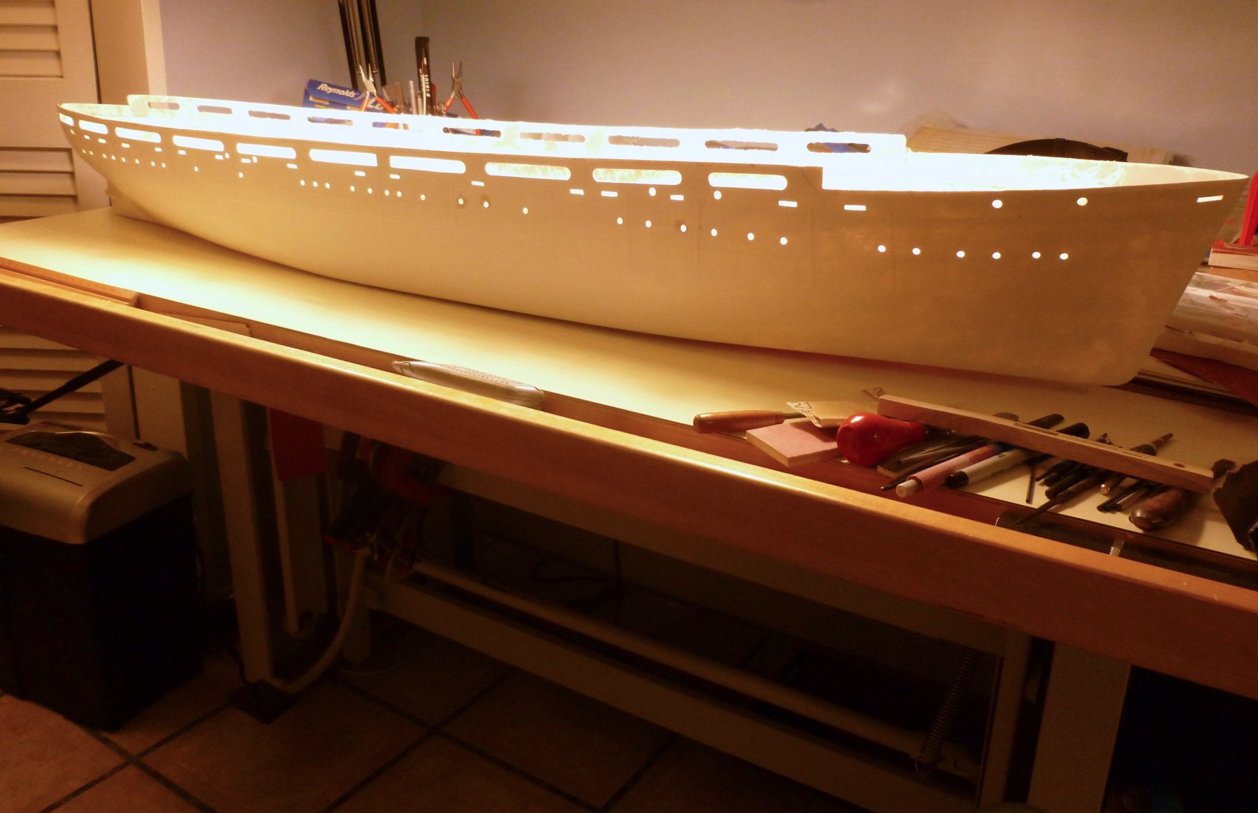
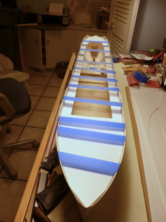
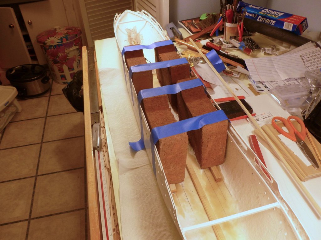
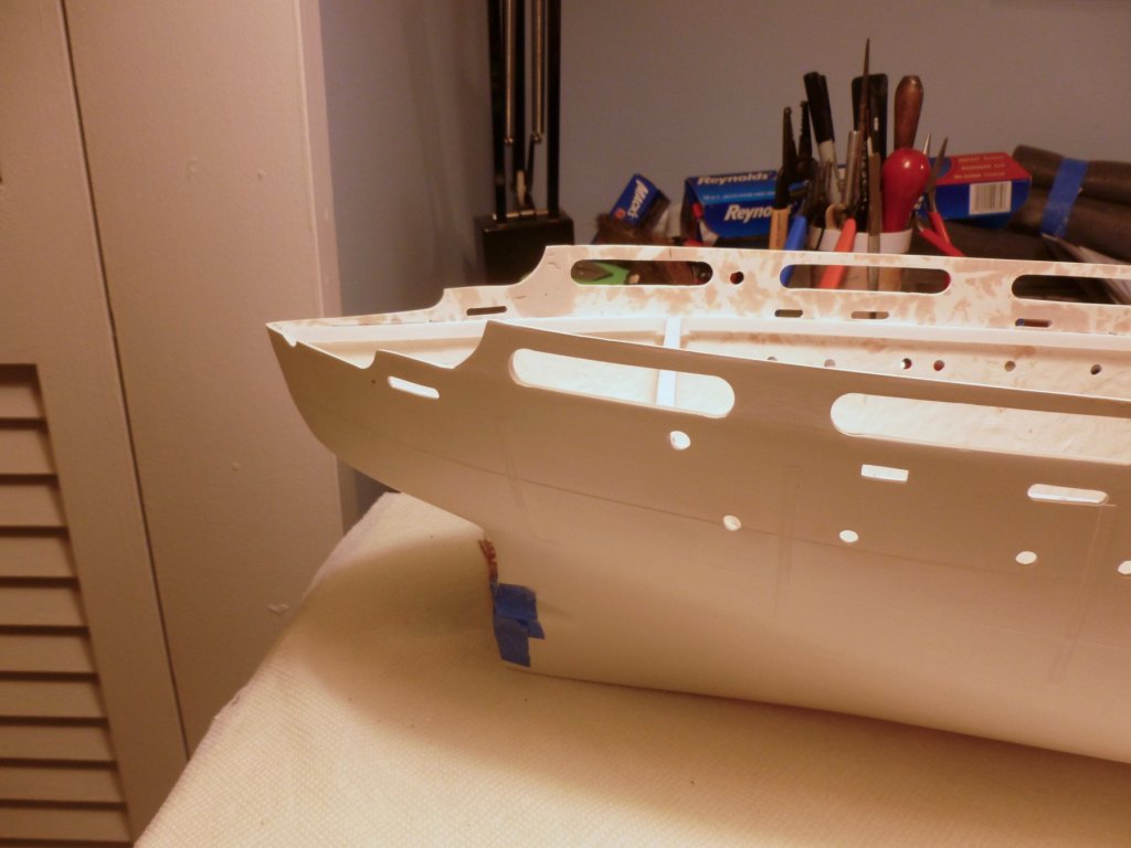
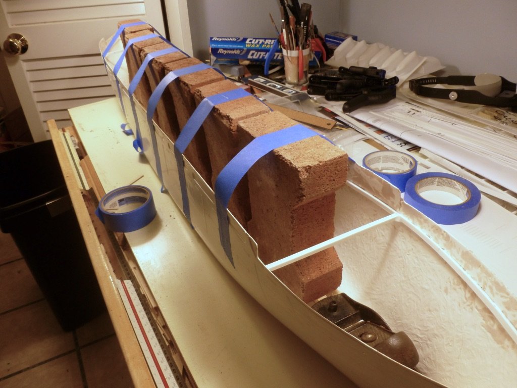
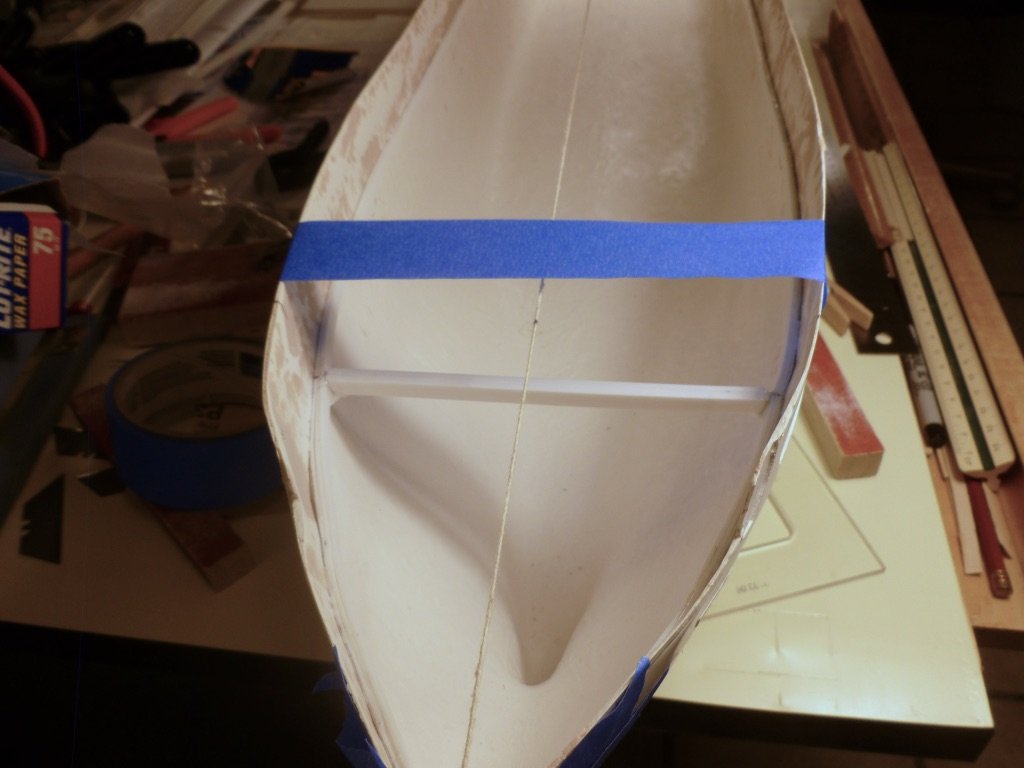
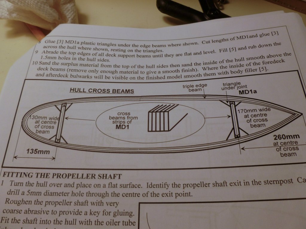
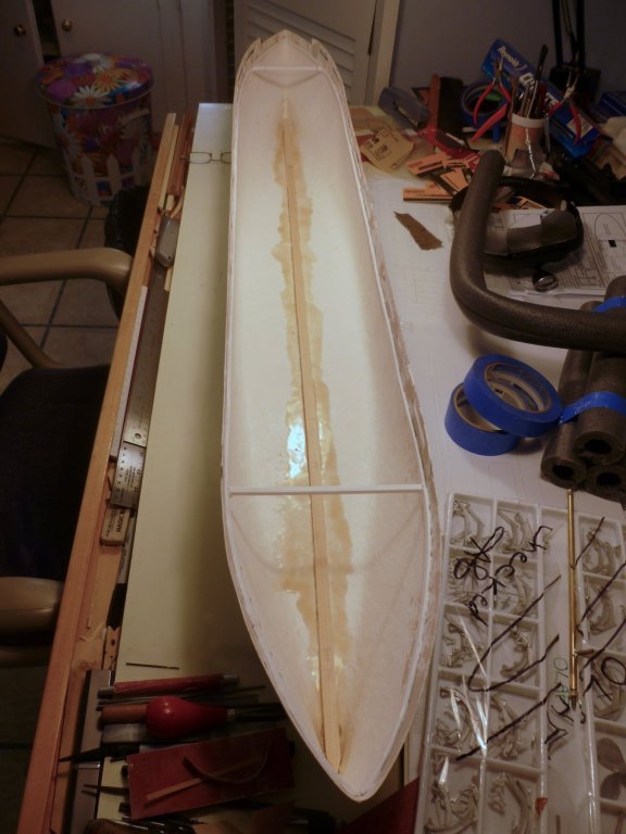
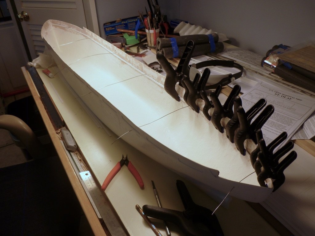
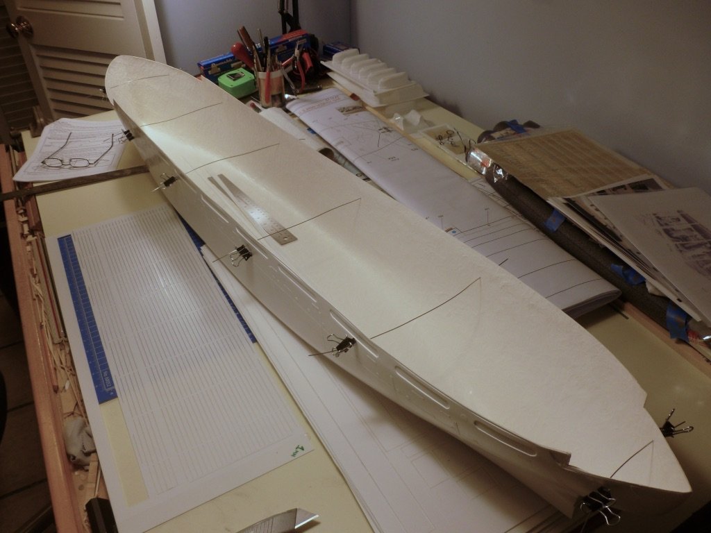
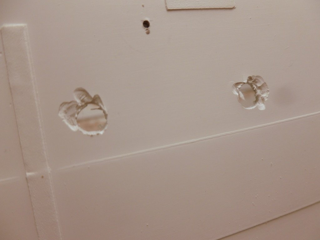
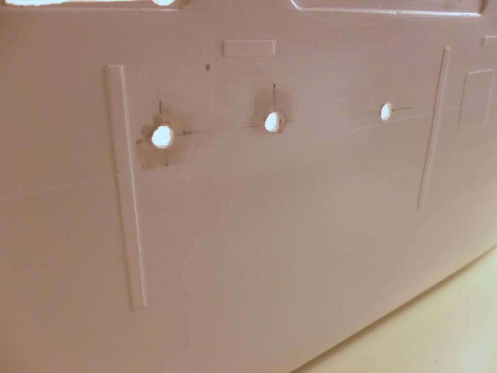
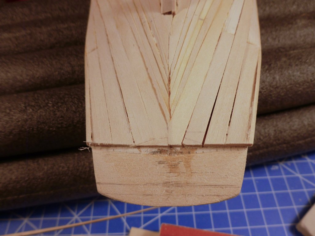
To all who gave likes, thank you and thanks for stopping by. Chris, thanks also for stopping in, and for your support and encouragement. Steve The first order of business was to squeeze the 54 inch hull into the shipyard. Thankfully my work surface is 60 inches long. The hull needed to be scrubbed with dishwashing liquid and warm water to remove mould release, then air dried after rinsing. Apparently rubbing the fiberglass dry with a towel results in static build up which causes problems with paint. Piano wire, which is installed through small holes drilled in the hull, provides a guide for placement of the perimeter deck beams. The instructions show nice straight lengths but when the local piano store sold me some wire it came off a roll. Deuce of a time getting it semi-straight. I tried the stretching trick used to straighten brass wire but believe me, piano wire doesn’t want to stretch. The perimeter deck beam is built up with three layers of laminated styrene strips from the laser cut sheets. The strips aren’t that stiff so the gluing clamps must be close together to keep the beam aligned with a layout line I marked using a flexible metal straightedge. The line at the bow and stern needed tweaking since the straightedge doesn’t do a compound curve. The brown on the inside of the bulwarks is Bondo, used to smooth out the rough backside of the fiberglass since portions of the bulwarks are visible. Priming will tell whether the extensive sanding provides a reasonable finished surface. The instructions call for two cross beams, each laminated with 5 strips of beam material and supported at each end on beam seats made of styrene triangles glued to the underside of the perimeter beams. The question was how to align the beams perpendicular to the hull centerline. I stretched a string the length of the hull, marked it at the cross beam distance at each end, then held a triangle on the mark and parallel with the string while I marked the bulwarks on each side. I extended the marks down to the perimeter beams. The tape is to hold the hull, which is quite flexible on its own, to match the cross beam dimension while the glue dries. There is a wood stiffener along the hull centerline, sort of a poor man’s keelson, to help keep the hull flat. The wood is set in a layer of fiberglass resin and must be weighted down while the resin cures. Some spare patio blocks, with a block plane for a helper, did the job. The finish shot is below. There are many holes to be drilled, routed and filed along the hull. For the portholes I saw a tip for using a brad point drill bit on fiberglass. The problem is that the hull fiberglass is thin relative to the brad point. When the brad point passes through the hard gel coat it moves rapidly through the glass mat and charges out the back side, causing the perimeter points on the bit to slam into the gel coat, which responds to the insult by chipping out. The pics below show the result on the first two portholes (3/16 inch diameter) and the later repair. After that I used a small conventional bit for a pilot hole, which then allowed me to slowly introduce the brad point, using a very slow speed to let the perimeter points gradually score the gel coat. This worked much better. The small hole above and centered between the chipouts is the drilling for the piano wire which was filled and sanded. The short horizontal strips in the hull are the scupper locations. The vertical strips moulded into the hull represent rub rails that were added to discourage damage during delivery of injured soldiers at sea. I expect they will need some weathering, which I have never done before, and your suggestions are most welcome. I don't want the ship to look a complete wreck since the voyage I'm targeting was immediately after the Vance came out of post-hospital re-fit. The long promenade openings at the top of the hull were roughed out using a Dremel with a side cutting bit, after drilling a pilot hole, but the scuppers were too small for it. The photo above shows the tools, including an ancient rat tail file, that were used to finish the scuppers after chain drilling each scupper with a 1/16 inch bit. I’m sure there is an easier way but my tool choices are limited. The starboard hull holes are essentially complete, although now I have to figure out how to fill all the portholes so they will stand up to water entry during sailing. The instructions call for taping the outside of each porthole and filling with clear epoxy from the backside, but if you have any better experience please let me know. I have heard about Kristal Klear but I saw a comment that it is very thin when it sets so I don’t know how it would hold up. These first two episodes are mostly retrospective since I started in mid-August, then picked back up after returning from holiday. Future posts will be more stretched out to correspond with the work.


- 446 replies
-
- 11
-
-
- zebulon b vance
- deans marine
- (and 3 more)
-
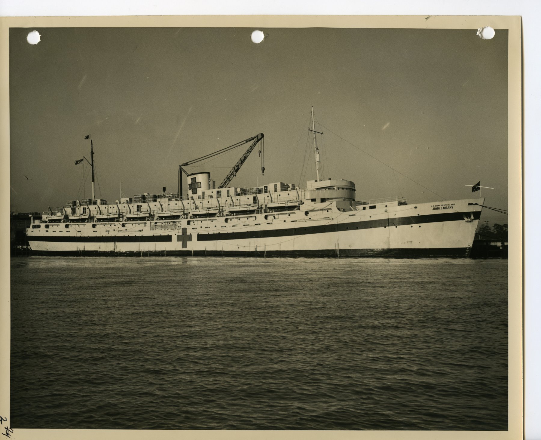
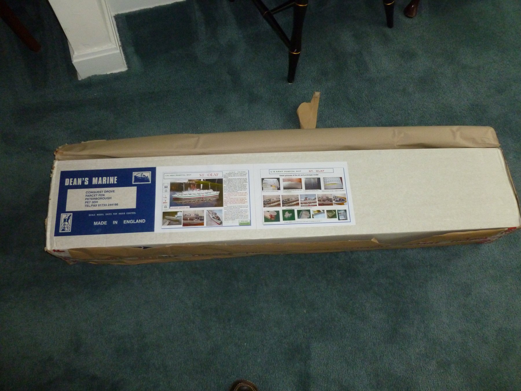
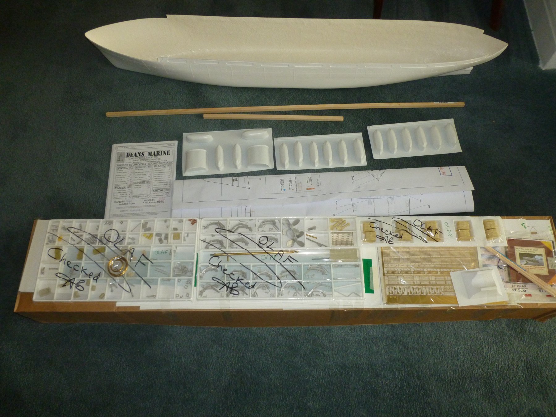
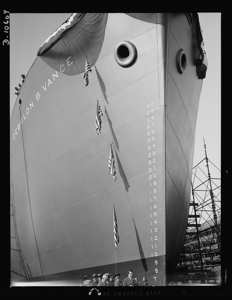
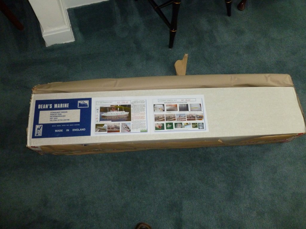
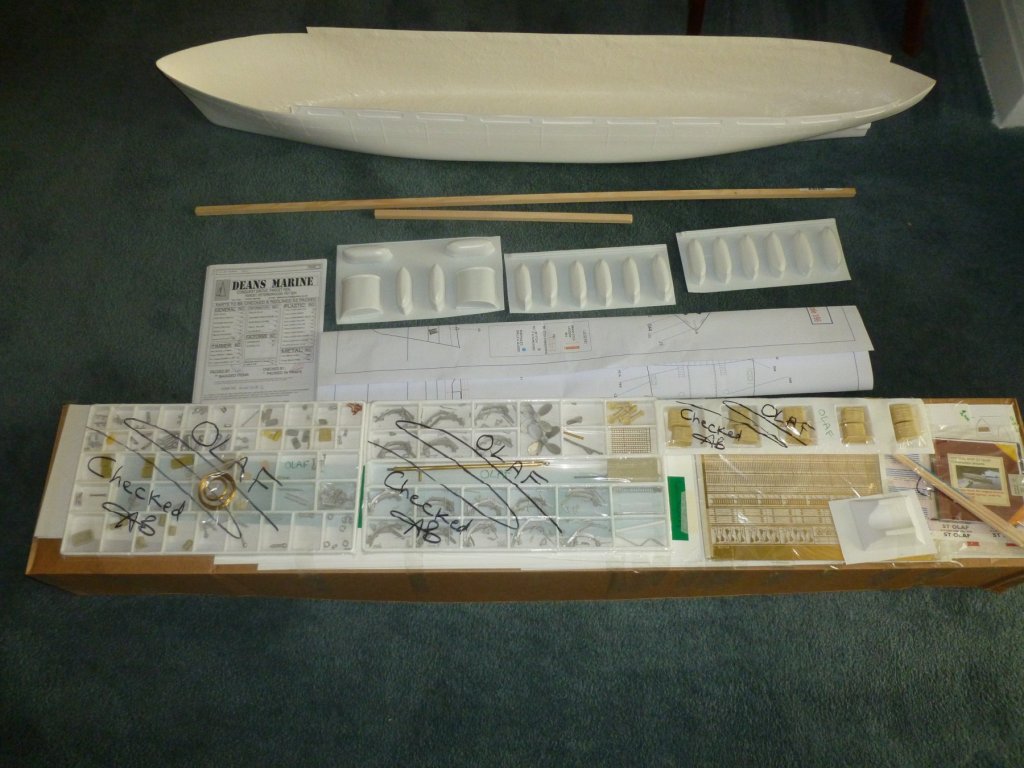
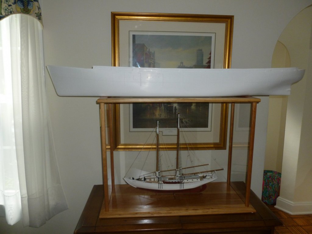
This is a build log of the Zebulon B. Vance, based on the Dean’s Marine kit of the St. Olaf hospital ship, which was a sister ship to the Vance. My interest in the Vance was kindled when I was casting about for a new project after completing my first wooden ship build (Bowdoin by Bluejacket Shipcrafters which is chronicled elsewhere in MSW). My late mother was a WWII war bride who sailed from England to New York shortly after the war ended, and I thought if I could find and model her ship it would make a lasting gift to our family. And an interesting journey it has become. Before I get too far I would like to thank the following individuals and organizations for their feedback and assistance: James E. Atwater, Assistant Curator, U.S. Army Transportation Museum James Smailes, Ship Plans Office, Smithsonian Institution Textual Reference Archives II Branch, National Archives at College Park, MD Nathan G. Jordan, Archives Specialist, National Archives at Atlanta, GA MSW member Koa4225 The Statue of Liberty-Ellis Island Foundation, Inc. The Library of Congress An excellent book on the subject is Hospital Ships of World War II An Illustrated Reference, by Emory A. Massman; McFarland & Company, Inc., 1999; which I purchased during the course of the research. The photo above from the Library of Congress (source C. Seavey, 2017) is of the Zebulon B. Vance launch on December 6, 1941 at the North Carolina Shipbuilding Company in Wilmington, NC. The Vance was originally a Liberty Ship, the first of 90 to be built at the North Carolina shipyard. After several years of service the Vance was reconfigured to a hospital ship at the Bethlehem Steel yard in Boston, MA, one of six identical Liberty ships to be changed to support the growing need for transport and care of injured soldiers. In its hospital mode the Vance was renamed the U.S. Army Hospital Ship John J. Meany. In addition to new paint and red cross insignia the conversion added multiple decks and structural enhancements to support the new loads. The photo above, courtesy of the National Archives, shows the Meany in its hospital wardrobe. The Meany made six transatlantic voyages. At the conclusion of the last voyage to New York on January 1, 1946 the Meany was removed from hospital service and given a one month retrofit at the Bethlehem Steel 56th Street Yard in Brooklyn; to serve as a personnel carrier for the multitude of war brides and refugees traveling from England and Europe to the U.S. The Zebulon B. Vance name was restored. By this point the Vance was pretty tired and the quick changeover, illustrated in the photo below courtesy of the National Archives, did nothing to enhance its appearance. Pretty or not I’m guessing the Vance’s initial docking at Southampton, England was a welcome sight to over 500 war brides looking to escape the horrors and devastation visited upon their homeland. My mother was one of those brides who packed into the ship, three bunks high with no bathroom privacy, for the 16 day voyage. In later years she referred to the Vance as a “tramp steamer” and said she was sick the entire trip. When she arrived in New York in late February my dad met her at the dock. As they walked to the car he said, “You’re in the United States now, you have to know how to drive.” So he taught her, on the 150 mile trip north to Troy. She was a good driver after that, although I’m not quite sure how she did it after being sick for almost three weeks. I suppose it was child’s play after enduring the Blitz, V-2 rocket explosions while sitting in the park and other war traumas. So here we are. Having only one build under my belt I did not feel qualified to scratch build the Vance, nor did I feel I had the skill to kit bash a Liberty Ship model since the superstructure is so different in the Vance’s post-war configuration. I chose the Dean’s Marine kit because the St. Olaf was one of the six Liberty ships to follow the Vance’s reconfiguration to hospital ship, and because the post war Vance looks essentially identical to the St. Olaf except for paint. The downsides are the kit is large (54 inches) and the construction is fiberglass and laser cut styrene. Many of the new skills I learned with the wooden Bowdoin must be put on the shelf in favor of wet sanding, fiberglass resin and Bondo. The upside is that I have purchased the RC bits and pieces and I hope to recreate my mother’s voyage across the pond, with the pond near our house sitting in for the North Atlantic. Let’s get to it. The kit arrived well packaged, in a shipping box nearly as tall as the Admiral, and in a remarkable 4 days from England. In addition to what is shown the kit includes many sheets of laser cut styrene and a CD with a full range of photos. There are two instruction books, one more of a reference and the other more step-by-step. And about 1000 pieces of PE brass, 600 of which are railing stanchions. The Vance’s hull was placed on top of the Bowdoin case for scale reference. The Vance is 1:96 and the Bowdoin is 1:48.


- 446 replies
-
- 14
-
-
- zebulon b vance
- deans marine
- (and 3 more)
-
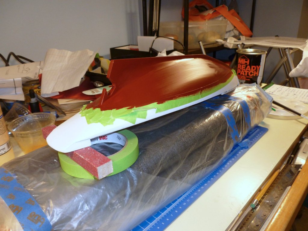
And here's a few more after masking was removed. Thanks, and remember if you don't like the paint, sand it down and do it again. When I did the inside of the stern block I shook the small bottle of primer but forgot to stir it well. The primer stayed soft and nothing I could do would cover it - it kept bleeding through. So I stripped it off and started over. Steve

- 48 replies
-
- 4
-
-
- first build
- bowdoin
- (and 2 more)
-
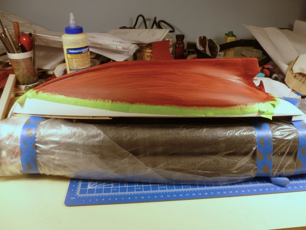
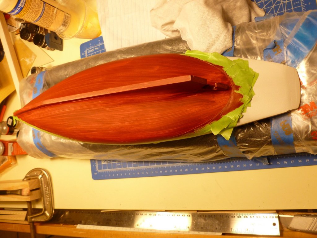
Zachary, The short answer is many years of painting around the house, one plastic model (Revell Saturn V) which taught me some skills at using small brushes and careful masking, and a bunch of reading on MSW. The rest of it was patience (prep and repeat, paint and repeat) until it looked like I wanted it. There was zero speed. As for what I did on Bowdoin see below. I've also included some pics at the end. The suggestion for using the ready-patch to "butter" the entire hull before starting the main sanding came from Charlie at Bluejacket. After multiple rounds of sanding back to the wood, filling the remaining low spots, sanding down the high spots and doing it all again, the hull was quite smooth. I spray primed with a can of KILZ because I have used it on projects around the house and found it to be a good sealer/primer. It took more than one coat because the primer highlighted any remaining defects, that needed filling/sanding again. I tried to keep the coats light. Then I drew the waterline and taped along the line with an automotive masking tape which had enough flexibility to follow the curves. I placed the tape so I could brush paint the upper hull white. I wanted to brush the final coats since I understand most ships were brush painted and I wanted some fine brush strokes in the finish. At the stern I had to use some shorter pieces due to the severity of the curve. This required several coats, again with sanding and spot filling in between. After the white was thoroughly dry I pulled the masking tape off and re-masked the waterline, on the other side of the line, to give me a sharp edge against which to paint the lower hull the red color. I tried to use the same number of coats of white and red so the line between the coats would be flush at the surface of the paint. When I removed the second masking there were some small bleed areas of red over white where the masking tape wasn't fully burnished down. I was a bit chagrined, but soon discovered that by using my magnifier headset, a no. 11 blade and more patience I could scrape off the red bleeds without damaging the underlying white. It's amazing what you can do when you take your time working close up. After the color painting I flattened the paint with a combination of paper towel followed by Kleenex, again based on a tip I saw. These have just enough roughness to the surface to smooth the paint. After all that and a final wipe down I sprayed a few coats of Testors dullcote to remove any gloss. Here are a few pics:
- 48 replies
-
- 2
-
-
- first build
- bowdoin
- (and 2 more)
-
Piet, I just discovered your wonderful project. Your finished build has a terrific sense of motion and action, and combined with your story telling the diorama truly captures what must have been a harrowing moment of desperation. Well done, and Godspeed to you and your family. Thank you for sharing this remarkable journey. Steve
- 378 replies
-
- 7
-
-
- java
- pacific crossroads
- (and 2 more)
-
Also, thanks for all the recent likes. I don't check the site every day since the work is finished except for answering questions, but I really appreciate your ongoing interest. Steve
- 48 replies
-
- 1
-
-
- first build
- bowdoin
- (and 2 more)
-
Mark, thanks for stopping in and thanks for your comment. I learn something new every day from the kind members of MSW and NRG. Steve
-
Zachary, I used the metal ones that came with the kit. I spray painted them after lining them up on a piece of tape turned sticky side up and secured at each end with another piece sticky side down. If I did it again I'd probably try the blackening (in the brown color) solution because the paint tended to chip during rigging. After cleaning up the metal flash on the blocks I used an x-acto no. 11 blade to deepen the stropping groove around the block, and I used a small drill bit to ensure the block holes were clean and well reamed - the rigging thread with beeswax on it was a tight fit otherwise. I used the kit black thread for stropping and seized the stropping with 6/0 uni-thread available through fishing supply stores. J Brent has a nice Youtube video that shows a simple way to install the seizing. Steve
- 48 replies
-
- 2
-
-
- first build
- bowdoin
- (and 2 more)
-
Steven, Your work at such a tiny scale with such delicate lumber is very impressive. Congrats on a wonderful build. Steve
-
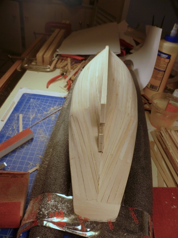
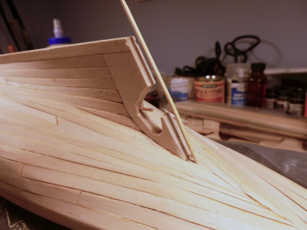
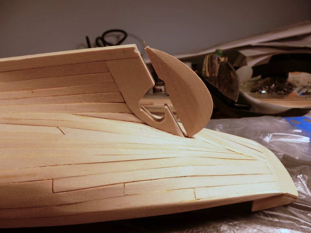
Ian, thanks so much for your compliment. I truly appreciate it. Zachary, below are some stern pics. The instructions said to install the first four or five planks full width but that left little room at the stern to work with. If I did it again I think I would have tapered all the planks so that those at the stern weren't so severely spiled. The saving grace was that the hull was filled and painted which hid a lot of planking sins. Thanks again for your help on the Vance. Steve The other thing I noticed in the stern area was that the cutout in the rudder didn't seem to align very well with the corresponding cutout at the stern post. It may be a question of how I shaped the rudder at top and bottom. That may have thrown the alignment off.

- 48 replies
-
- 2
-
-
- first build
- bowdoin
- (and 2 more)
-
A very elegant build and an equally elegant presentation. I think the case looks great. I particularly like the 3/4 view. Who looks through the curved edge at a model anyway? If it was wood framed the edge would block the view completely. Great job, and thanks for sharing. Steve
- 190 replies
-
- 2
-
-
- pinnace
- model shipways
- (and 1 more)
-
Harley, Thank you, and thanks for looking in. Steve
-
Zachary, The masts are not glued in. Cutting the mast bottom into a rectangular shape is important to keep the mast from spinning around when you put tension on the rigging. I tapered the masts, booms and gaffs by hand, partly because I cut them to length before seeing the tip about chucking one end in a drill and then cutting the piece off that gets chewed up by the drill bit. I didn't have any spare mast length to work with. I used mostly the paint set that I purchased with the kit, supplemented with some from Model Masters and Testors. Spray primer for the hull was KILZ. Flat lacquer clear was Testors. I believe the "wood" on the binnacle was the Italian Dark Brown that came with the kit. I have bottles of Model Masters Brass 1782, and Testors Metallic Gold but I don't recall which I used for the top of the binnacle or the wheel hub. I also don't recall what I used for the lighter brown spokes It's possible I may have mixed some darker brown with a bit of white. I suggest just testing on a piece of paper to see what you like. I heard something about Testors not being available anymore but I don't know if that is true. Keep building! Steve
- 48 replies
-
- 1
-
-
- first build
- bowdoin
- (and 2 more)
-
Zachary, If you have sailed on Bowdoin you are way ahead of me in your research. The holes for the eyebolts in the rigging were all pre-drilled. Early in the build you will need to cut the bottom of each mast into a rectangular shape to fit into the mast step, a little slot you will form into the keel area. After I cut the rectangular shape I marked each mast below the deck line so I always knew which side was port, which was starboard and which side was toward the bow. Then whenever I laid something out on the mast I made sure it was aligned with proper direction I had marked on the mast. For the eyes I drew a line along the mast from the center of the mast rectangular shape and used that as a centerline for the eyebolt holes. I used the drawing of the ship to determine the vertical location of each eyebolt. The holes were drilled with a pin vise, making sure to keep the drill bit vertical. Good luck! Steve
- 48 replies
-
- 2
-
-
- first build
- bowdoin
- (and 2 more)