ESF
-
Posts
381 -
Joined
-
Last visited
Content Type
Profiles
Forums
Gallery
Events
Everything posted by ESF
-
 Ouizel, thanks for the suggestion. I read about using tissue paper but had not seen how to actually do it. I was thinking this morning that the handkerchief still looked too heavy. Steve
- 446 replies
-
- 3
-

-
- zebulon b vance
- deans marine
- (and 3 more)
-
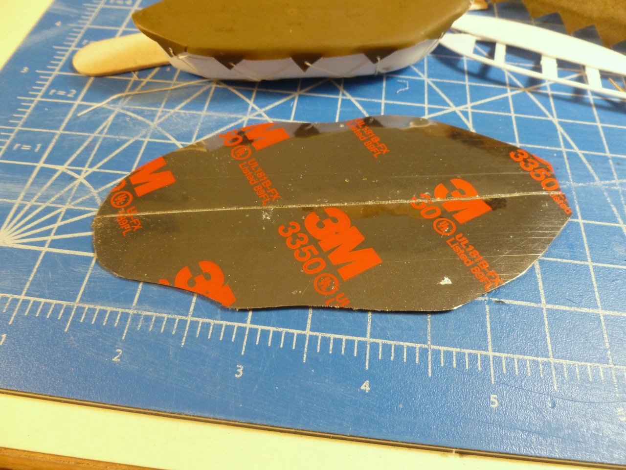
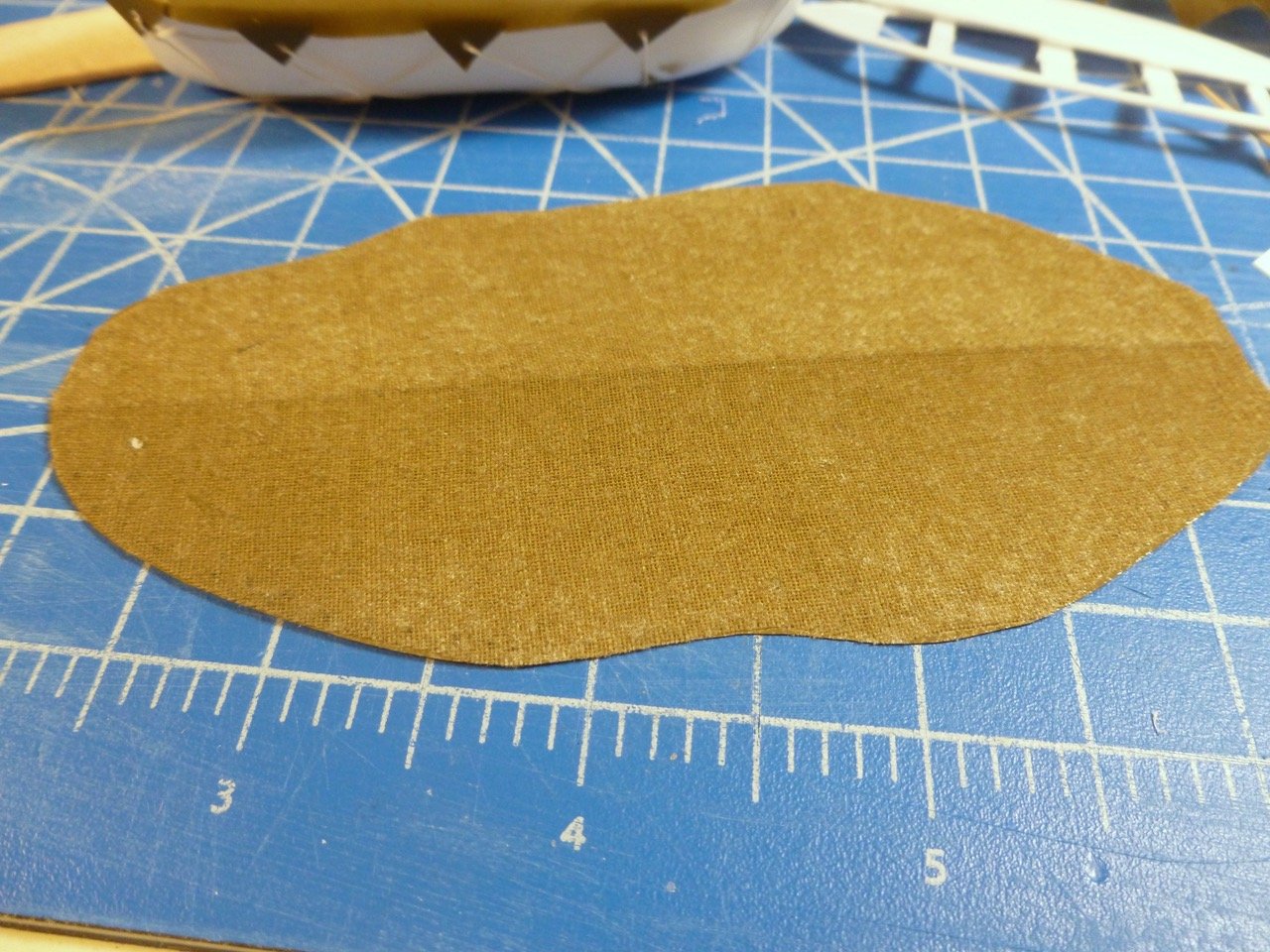
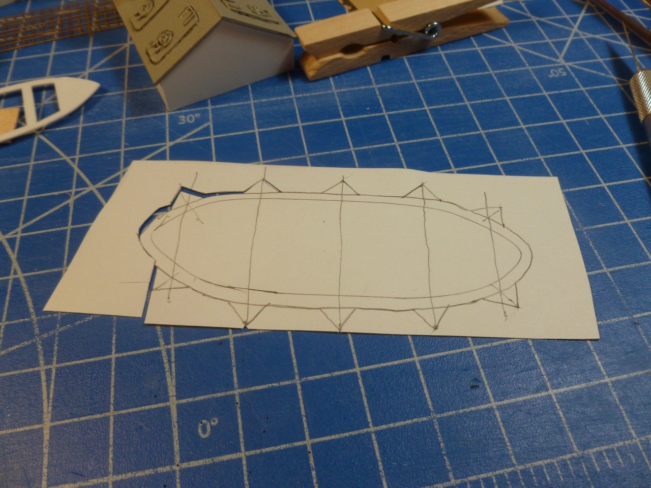
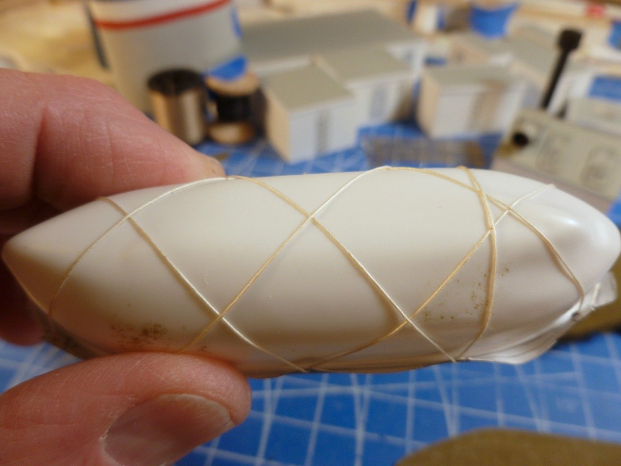
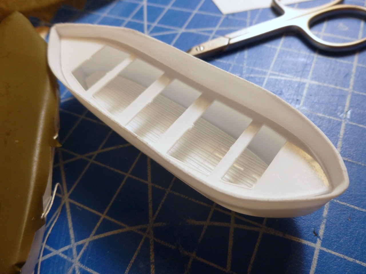
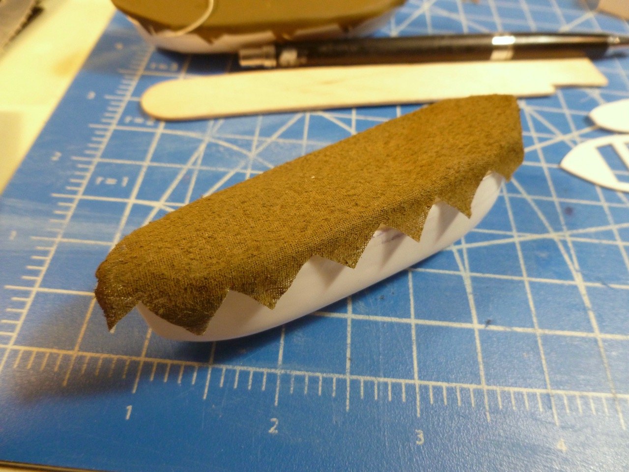
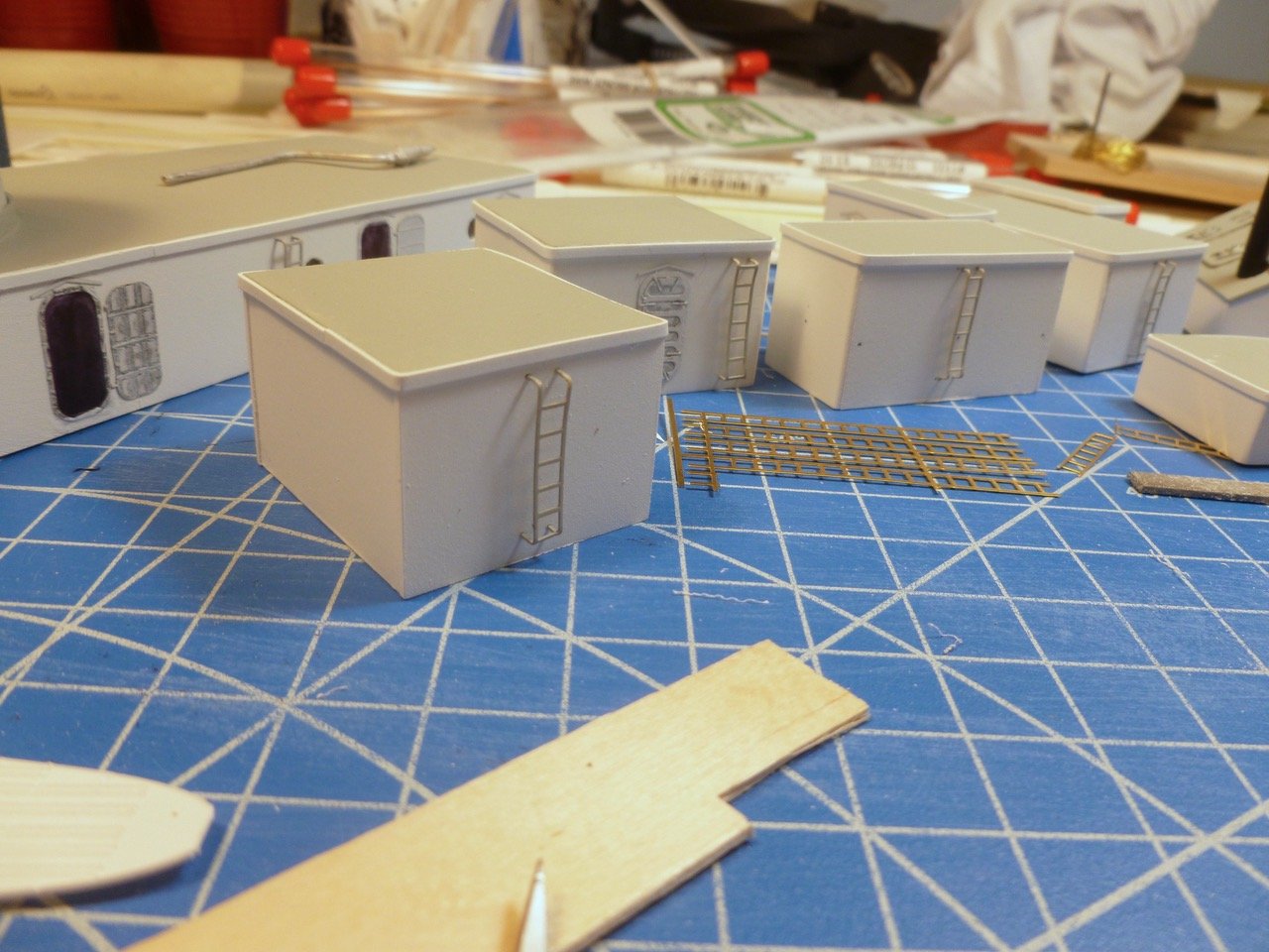
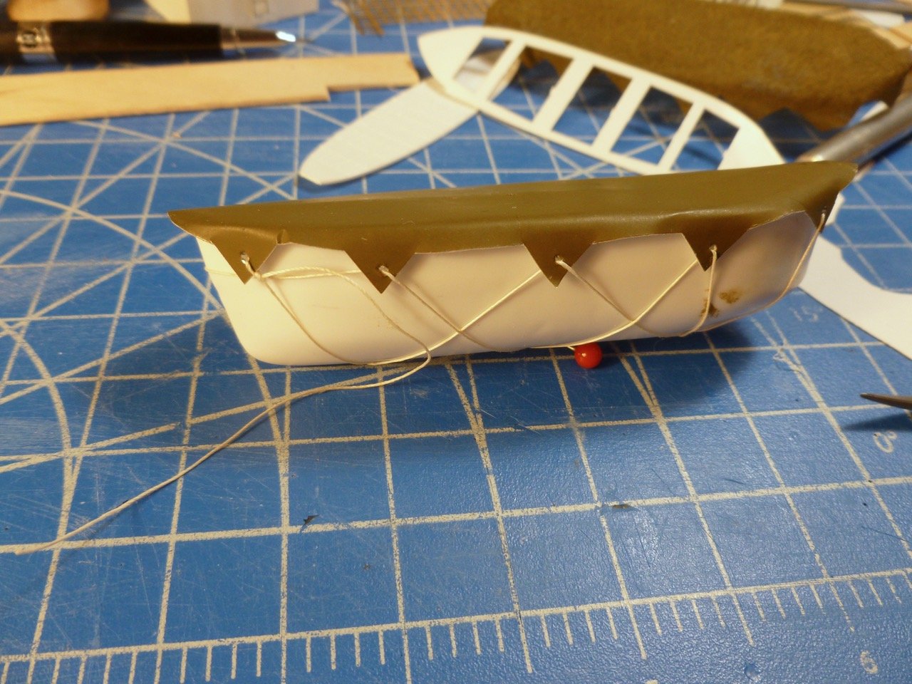
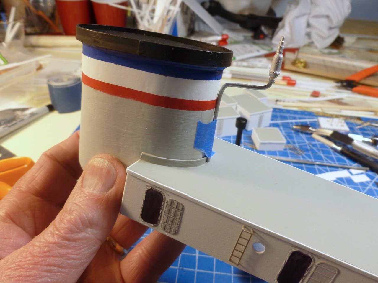
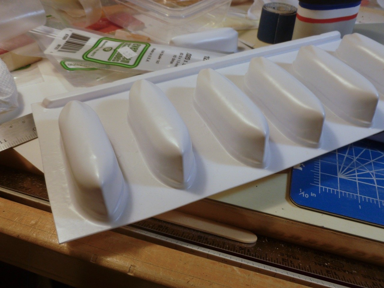
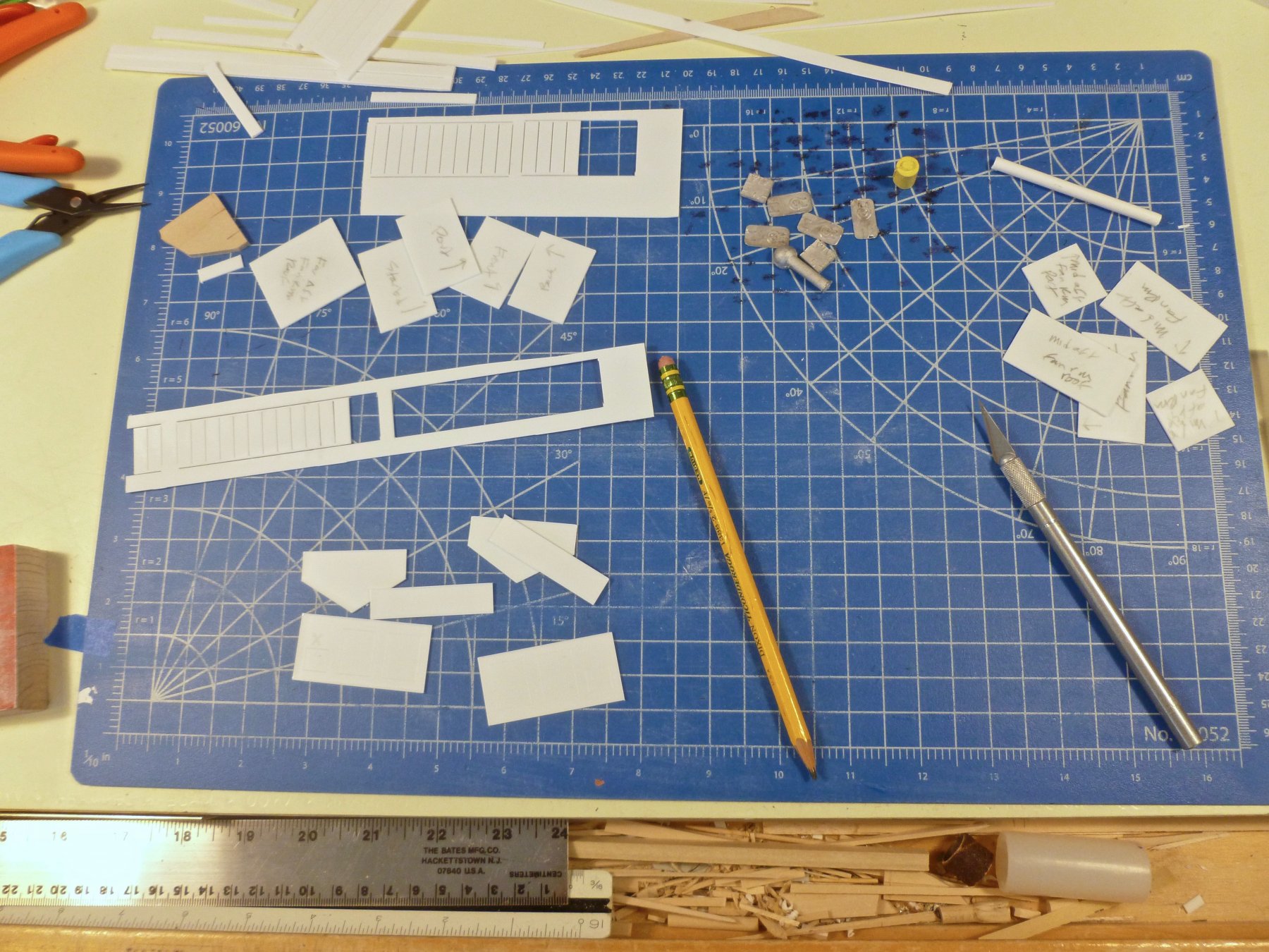
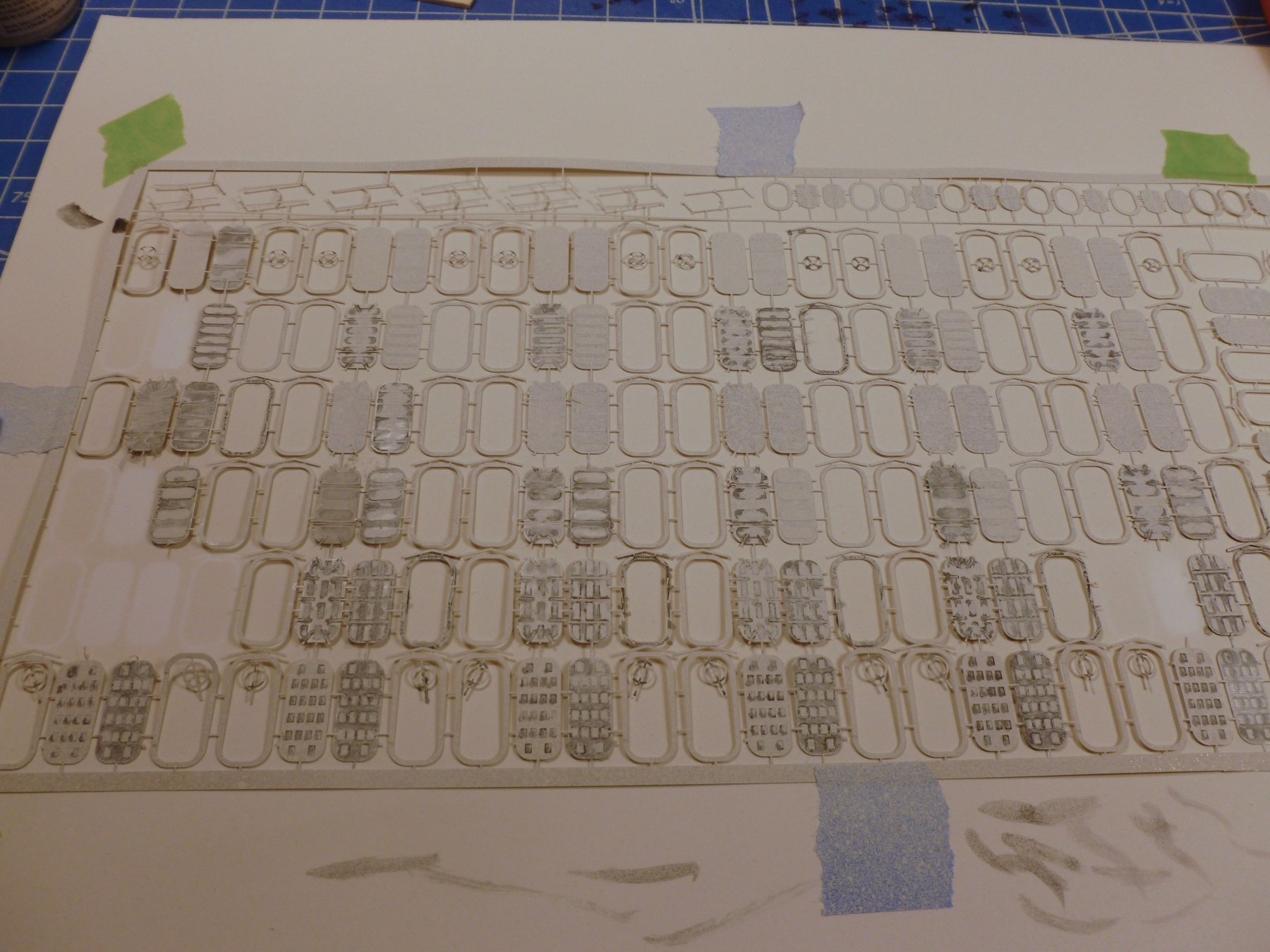
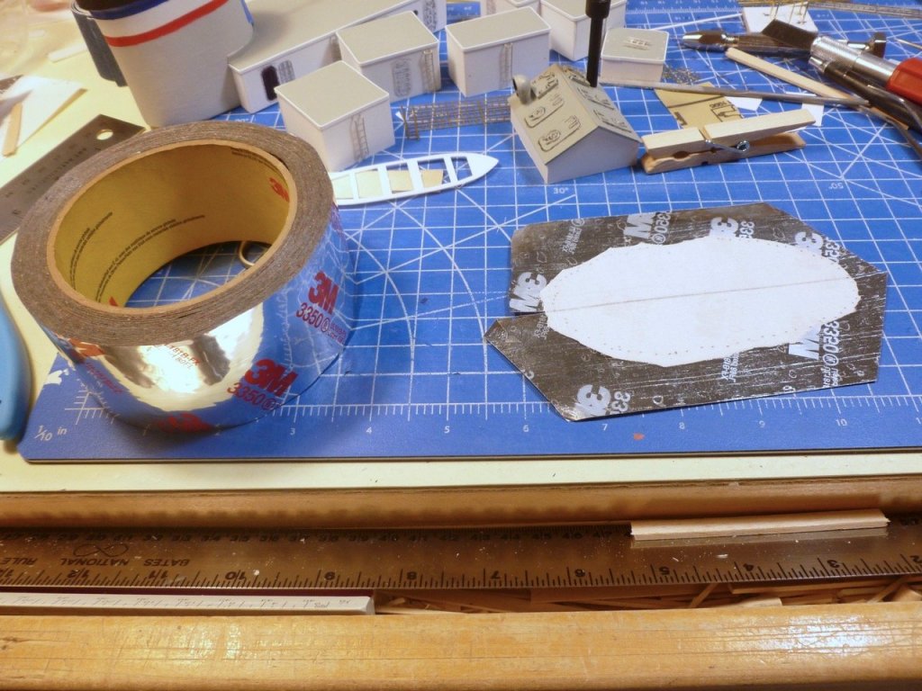
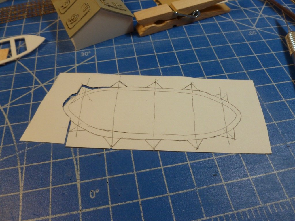
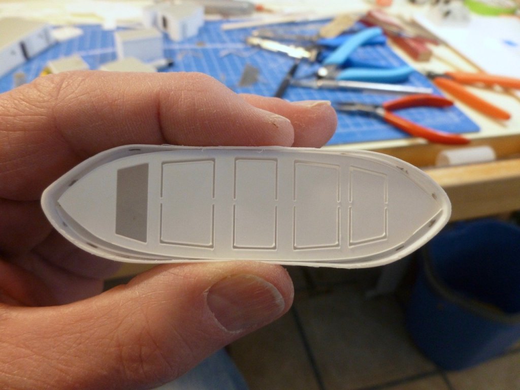
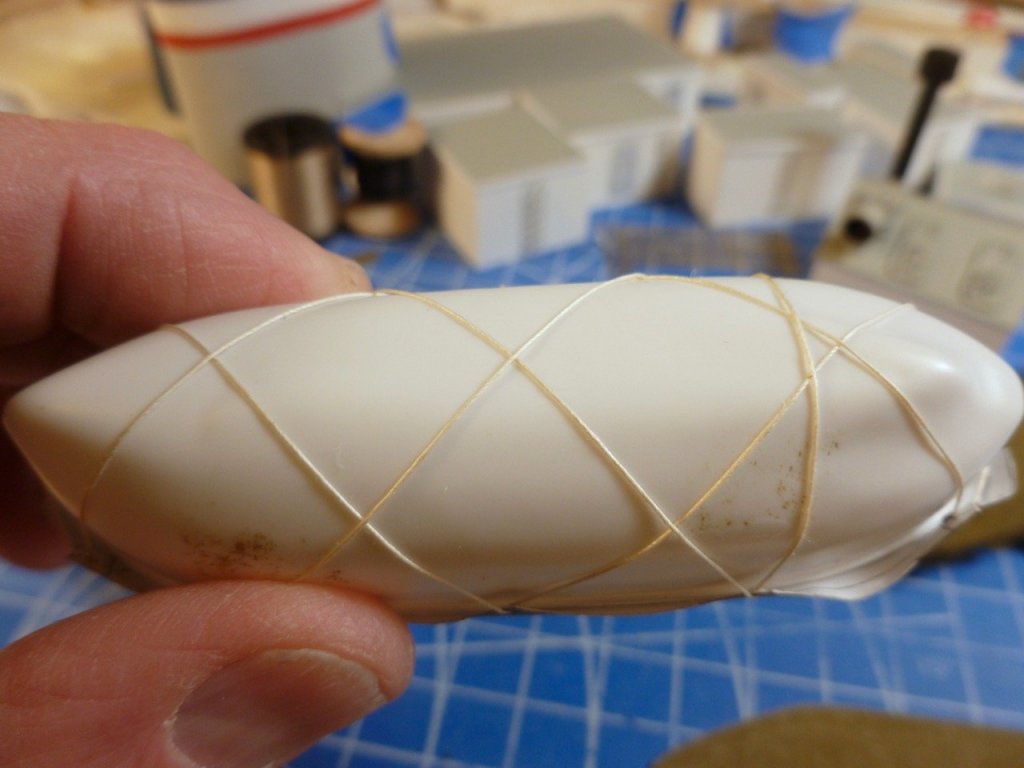
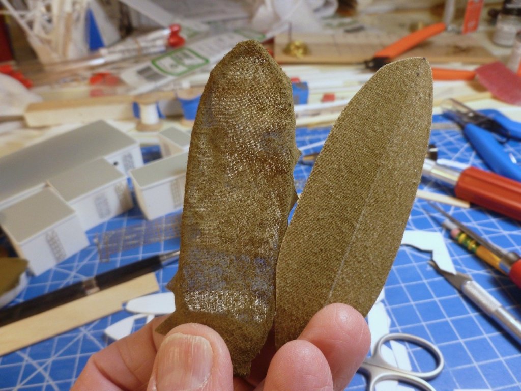
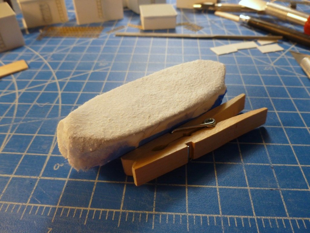
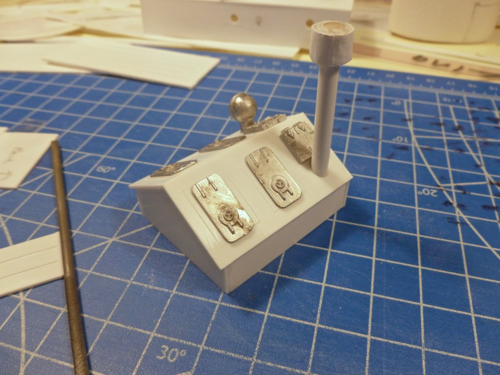
To those who gave likes, thank you and thanks for stopping by. Carl, thanks for the matte varnish suggestion. It worked well on the remaining doors, and the paint touch-up went without incident. Lesson learned - if I muck up paint, give it a chance to dry rather than trying to wipe it off. Steve Bitsa this, bitsa that this week. I fitted the PE ladders for the top deck cabins after giving them a shot of gray paint. I need to work on straightening them out after some exuberant pressing during the installation. The plan shows a circle near the front of the funnel, labeled with the steam whistle part number, but doesn’t show how it is installed. Various ship photos typically show the whistle up tight to the funnel, but this would imply the bent pipe coming from within the radio room. Alternatively the pipe could be flush with the funnel as shown in the pic. Any votes on which way might be correct? Or should I snip off the angled part of the pipe and mount the whistle at the funnel front? I’ve seen some mounted on what appears to be a pair of angle brackets fastened to the funnel. The ship’s boats (16 of them) are vac formed. I cut one out and after trimming the surrounding flash I installed a rub strip along the top edge, and added a seat support strip 4 mm down from the top. When I test fitted the seat piece it appeared way too small. This got me thinking about using covers in lieu of finishing the 16 interiors. After checking several logs for ideas I experimented with several techniques. First up was using an old handkerchief, stiffened with diluted PVA and sprayed with olive drab. Before the glue and paint I wrapped the unfinished test boat with wax paper to keep the handkerchief from sticking to it. The diluted PVA seemed to raise the grain in the cloth fibers. When I pulled the wax paper off it seemed to take some of the fabric with it, leaving the cover somewhat transparent. But the paint seemed to take some of the curse out of the raised grain. Next up was using 3M tape made for sealing heating ducts. This is a thin, foil faced material with good flexibility. I applied it to a piece of copy paper, and then painted the tape. The tape/paper combination proved quite strong but also quite smooth and less than flexible. But I gave it a shot with lashing only (no glue). The last test was 3M tape applied directly to the handkerchief, the thought being to get some texture but eliminate the transparency and add some strength. I painted the handkerchief but avoided the dilute PVA. The texture was better, there was good flexibility and by applying the tape in two pieces the assembly could be bent over the centerline of the boat. If I go with covers I may use this method if I can figure out how to glue the shiny tape surface to the side of the boat. The first try with CA pulled loose but that may have been a question of cleanliness, or lack thereof. The tape/cloth combo seems much more presentable than the cloth/PVA attempt. While working on the tests I mulled over what could be causing the mismatch between the boat and seat dimensions. I saw that the boat looked quite deep and without a noticeable sheer line. It occurred to me that the trimming might not only be for the horizontal flash, but also some vertical flash. Looking at the boat closer I saw what appeared to be a faint sheer line, down about 4 mm from the top. Casting caution to the wind I applied scissors and file to the boat and trimmed off everything above the line. Voila, the boat proportions looked much better, it had a nice sheer, and the new location for the seat support was at a narrower part of the hull - giving the seat a better fit. So, now the decision is to either install the kit seat and floor boards, paint it all up and call it a day, or start working on covers. Since I won’t be superdetailing the interiors I think the level of effort may be a tossup and I’ll probably go with the kit parts. And from what I have read I believe the boats would have been uncovered while underway anyway. If I don't use covers now at least it was an interesting learning experience.


- 446 replies
-
- 9
-
-
- zebulon b vance
- deans marine
- (and 3 more)
-
Well, I am trying it during my lunch break and the pics have uploaded. Not as sharp since I downsized them to email to myself. So thanks for the likes, and Carl thanks for the paint suggestion on the funnel and for your moral support. With construction of the top deck cabins complete I added the roof edge trim and doors. I finished the engine room vent roof and added some highlights at the vents. Then I started spraying dullcote to flatten out the funnel paint and the black infill at the open doors Guess what - "Permanent" black marker loves to dissolve in Dullcote lacquer. I now have about 4 doors that need paint restoration on the frame and surrounding wall. And a question remains - what can I do to flatten the remaining black marker without having it drool all over? Non-lacquer matte finish?


- 446 replies
-
- 5
-
-
- zebulon b vance
- deans marine
- (and 3 more)
-
I'm having the same -200 upload error for photos as are many others. I'm trying one of the suggestions, to upload text, then edit the text by adding photos. We'll see how it goes. Well, not only didn't it work, the attempted photo upload hung up and wouldn't do anything, not even a -200 error. I have offloaded the text since it is boring without the pics. I'll try again another day, but if it keeps up like this I may just abandon this whole posting thing altogether. There's enough aggravation elsewhere in the world without having to get frustrated trying to share a model boat pic. Rant completed.
- 446 replies
-
- 3
-
-
- zebulon b vance
- deans marine
- (and 3 more)
-
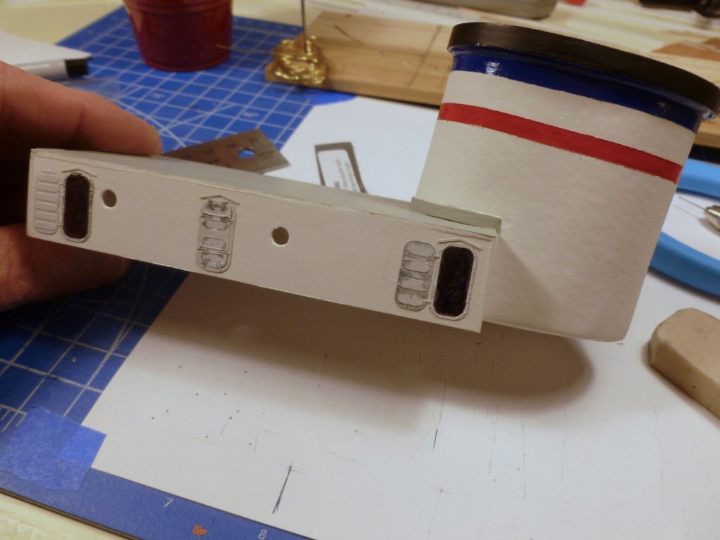
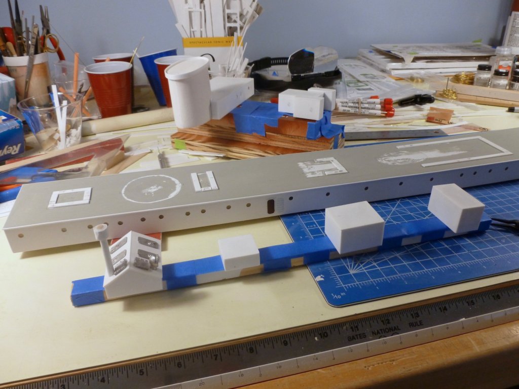
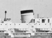
To those who gave likes, thank you and thanks for stopping by. Carl, thanks for the link to the eyebolts. If she sails in for dinner she better bring the food - otherwise there will be no room for it! I’ve been squeezing in work on the top deck, around trying to recover from bronchitis that doesn’t want to quit. I scraped within the footprints of the top deck cabins and the painted over red cross circle plates to get glue bonding, and added strips under each cabin to provide secure anchorage. I also painted the cabins and cabin roofs, added glazing for the remaining portholes and installed doors at all top deck areas, and I painted the sunshade over the bridge. The ship photo shows three stripes below the funnel top. I’m assuming the funnel top is black and I surmised the three stripes might be red, white and blue to celebrate the war victory. I have found no color photos of the Vance, but some other ship photos show red at the bottom. It seems consistent with the photo since the bottom stripe is a bit lighter than the top stripe. The middle stripe is wider and appears to be white. So I masked the funnel and painted a blue top stripe, proportional in width to the one in the photo, left the middle stripe white, also in proportion, and finished with a red bottom stripe. The result is below, although it hasn’t received its dullcote yet. After stripping the masking the red stripe appeared to be swimming in a sea of white. Returning to the photo I noticed that the funnel below the bottom stripe is something other than white, but not as dark as the bottom stripe. This makes sense since the funnel had two large red crosses when in hospital mode that needed covering up during the quickie update to bride transporter. So the question is, what color is the base of the funnel? I’m thinking gray but if anyone has any insight please chime in. I built a little jig for the multiple railings that go between the lifeboats on the boat deck. Ship photos appear to scale about 8 feet wide, and also appear to show the railings lining up above the solid areas between the promenade openings. To confirm the spacing I cut out the vac-formed lifeboats, cut some strip into 8 ft wide pieces and lined everything up on the boat deck. As the photo shows it was too long, pushing the last boat all the way to the aft bridge, nothing like the real ship. I started wondering if the lifeboats were too long and briefly looked into replacing them with something shorter, but there are 16 of them and I can’t justify the cost of that many replacements. So I experimented with narrower railing sections and at 5 feet wide the layout seems much more workable, as shown below. And yes, I know the lifeboats are upside down
- 446 replies
-
- 5
-
-
- zebulon b vance
- deans marine
- (and 3 more)
-
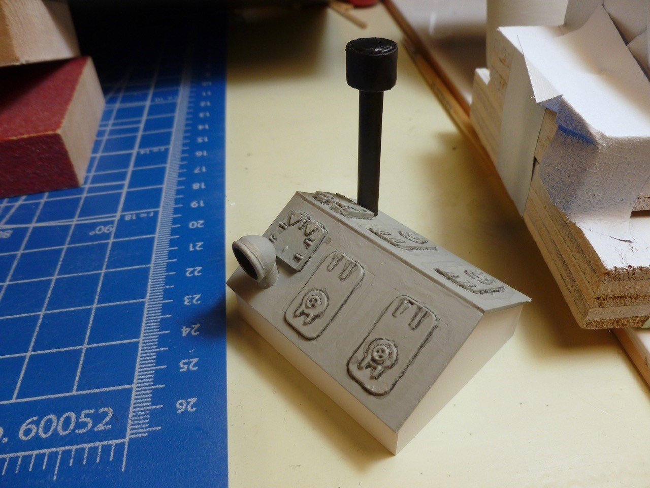
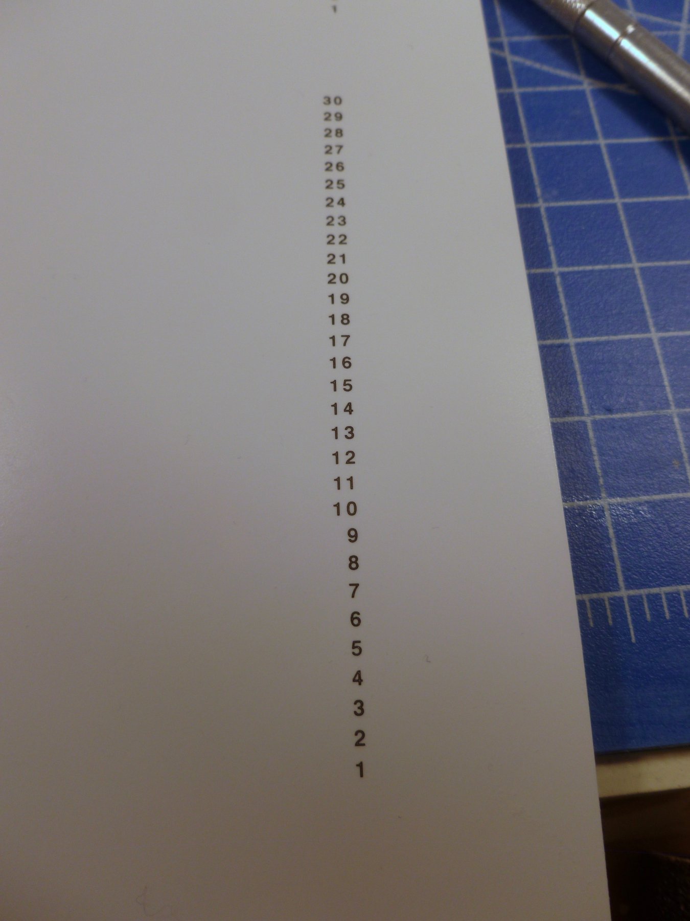
To those who gave likes, thank you and thanks for stopping by. Carl, thanks for your picking up on the storage rack for the propellor. I’m not sure if that is in cards since the prop is anchored with CA and a large wood peg glued into the prop and partially set into the main deck. Maybe I'll look into tiedowns into deck eyes. Steve Not a whole lot of work this week - family duties and a nasty cold that makes my nose run all over the worktable. On the plus side I saw light at the end of the cabin construction tunnel. In addition to four sides and a roof that must be cut from the laser sheet and sanded all sides, each cabin gets 2 stiffeners at each corner and 2 at each roof/wall intersection for a total of 16. Each stiffener must be sanded on both sides and the edges to remove the ridge where the laser melts the styrene. Then each cabin is positioned on four more strips glued to the deck. Since they are almost all basically cubes it seems they could have been supplied as blocks of wood - but then again the portholes would be more of a challenge, and it probably would put too much weight up high - bad for stability. The engine room vent is built but unpainted. I had to fabricate the exhaust cap since the kit piece, which didn’t fit the plastic tube anyway, made a brief appearance and then sailed off into parts unknown. The exhaust pipe seems tall but photos of the ship show it well above the vent roof ridge. The vent hatch covers are either too thin or the etched layout lines were too widely spaced. If the primer doesn't cover the lines I'll need to fill and sand. I purchased some clear waterslide decal paper and ink jet printed a strip of depth markers, with a coat of dullcote for protection per the manufacturer’s recommendation. I also printed up the ship’s name on clear decal. The historic photos show the text about half the height of the promenade openings. Does the position/size/font look about right? I'm wondering if the text should have been white - the black on dark gray may not be very legible. The circles on the top deck shown in the last update were taken off and I forgot to replace them before taking the pics today. Since I’m getting perilously close to the railing adventure I did a takeoff to see how much railing will be needed. Allowing for three bars at the perimeter, and one bar along the cabin walls, I need about 880 inches (22,352 mm?) of railing. After cleaning out the LHS twice I think I have enough. One question is whether I will need an angled strut every so often to stiffen the long runs of railing, or whether the medium CA will be sufficient.


- 446 replies
-
- 6
-
-
- zebulon b vance
- deans marine
- (and 3 more)
-
Bob, The result is terrific. If this is your least favorite (?!) you have indeed set an extremely high bar for yourself. I wish you the best of health in 2019 and beyond, and hope you have many more "one last build" with which to share your deep reservoir of talents. Thank you for giving us hopes and dreams. Steve
- 359 replies
-
- 3
-
-
- prince de neufchatel
- model shipways
- (and 1 more)
-
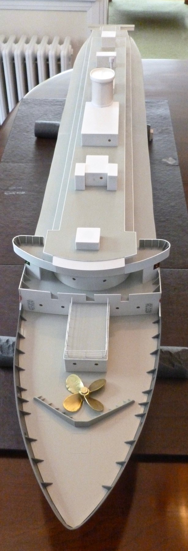
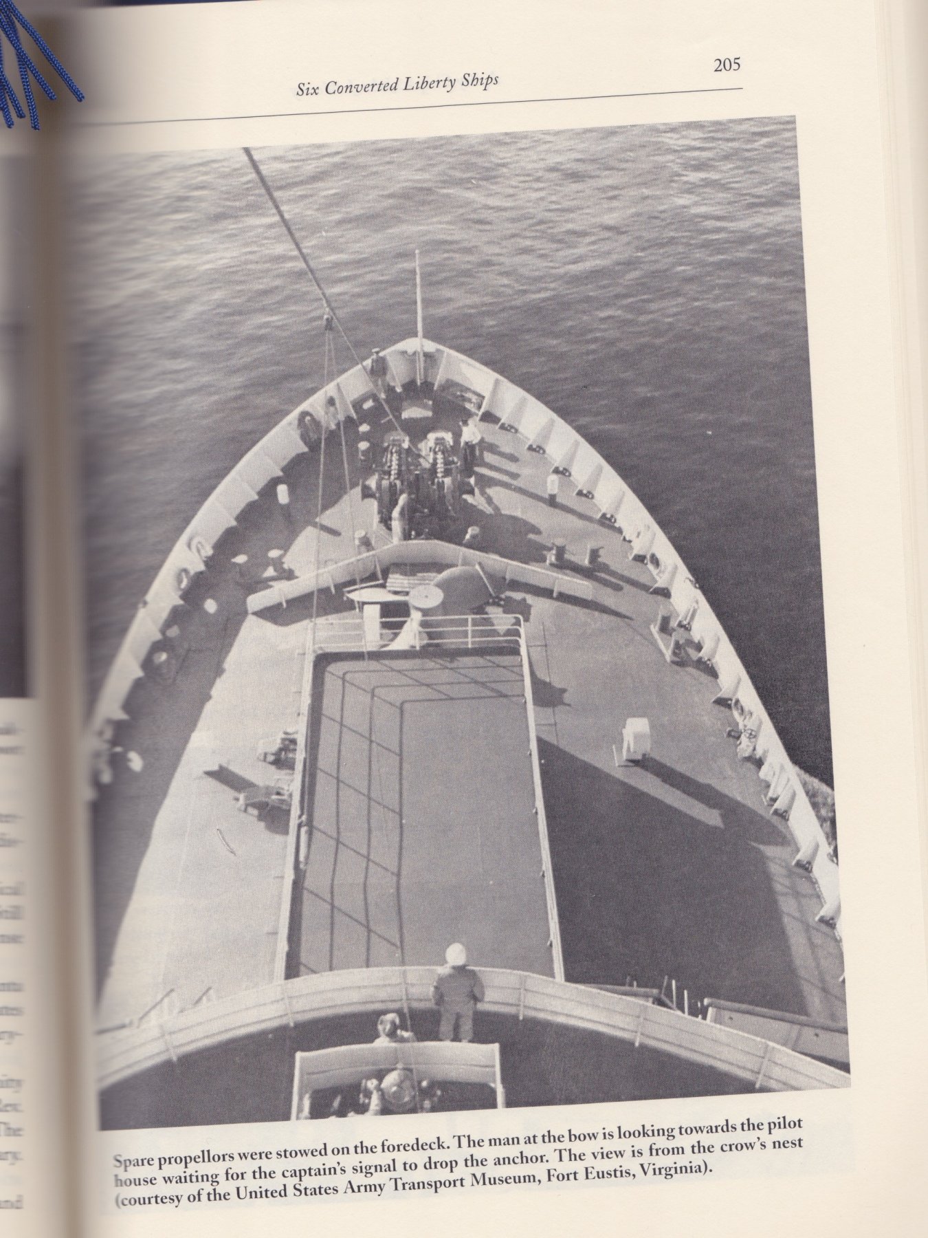
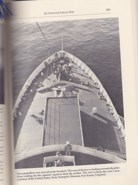
To all who gave likes, thank you and thanks for stopping by. Kevin, thanks for your compliments. I'm pleased with the work to date, although there are many areas to do better or learn something new. I don't progress as quickly as I'd like, but must balance shipbuilding with full time work and family. I think the kit is generally well made, but have found some inconsistencies in dimensions requiring some splicing in of extra material, and there's a need to thoroughly read, read ahead and ponder what you have read when navigating the instructions. Some pieces that are shown are not in the kit such as the microstrip for trimming the deck edges. If you choose to build as an RC model you should purchase a well made rudder arm with integral set screw when you are buying the RC bits, because the cast metal one with the kit cannot be secured properly - a self tapping screw strips the threads it cuts in the soft metal. But in general I'm enjoying the build and looking forward to the day it sails in the local pond. Carl, I truly appreciate your hanging in there and your very kind feedback. Bill, thanks also for your compliments. To all: The photo below from Emory A. Massman's wonderful book Hospital Ships of World War II - An Illustrated Reference, McFarland & Company, Inc. 1999; and courtesy of the United States Army Transport Museum, Fort Eustis, VA, shows and notes that spare propellors were stowed on the foredeck. Of course I also see that I put too many braces on the breakwater and those on the bulwarks are too big, the wrong shape and too few! Oh well, you win some, you lose some. Steve
- 446 replies
-
- 5
-
-
- zebulon b vance
- deans marine
- (and 3 more)
-
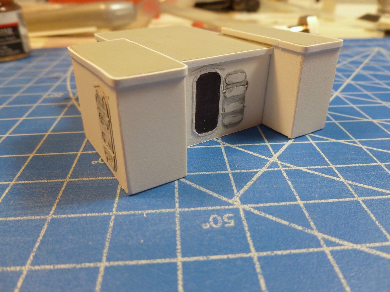
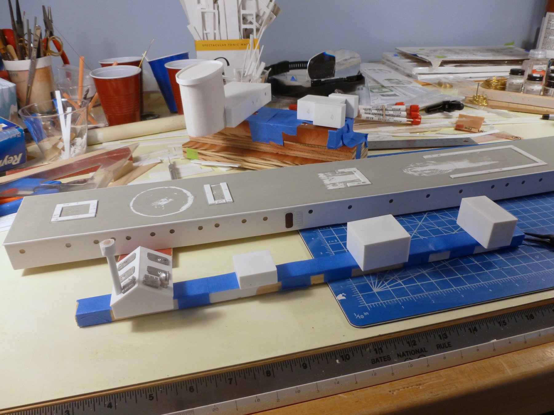
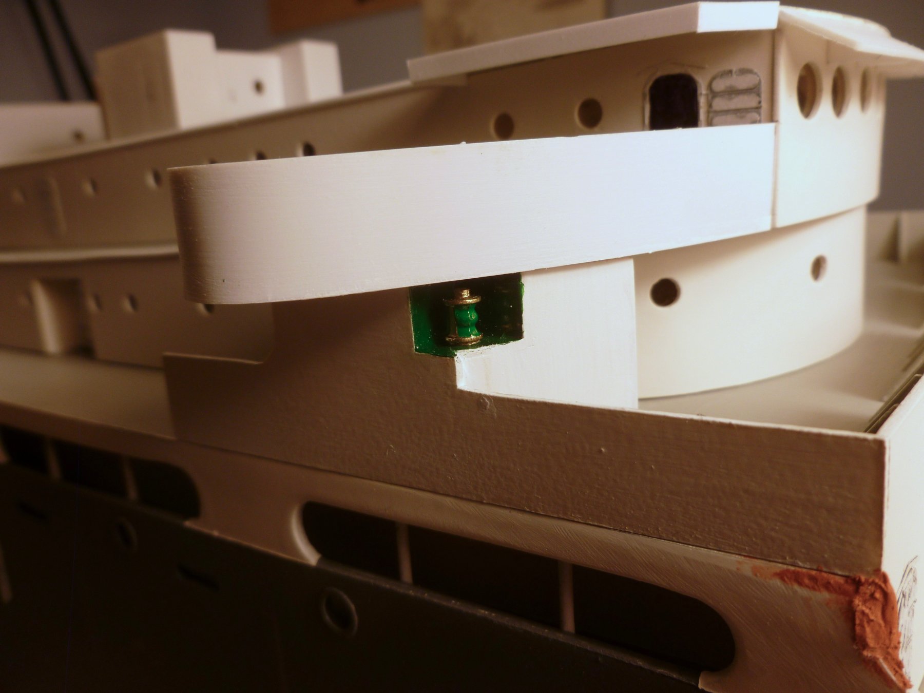
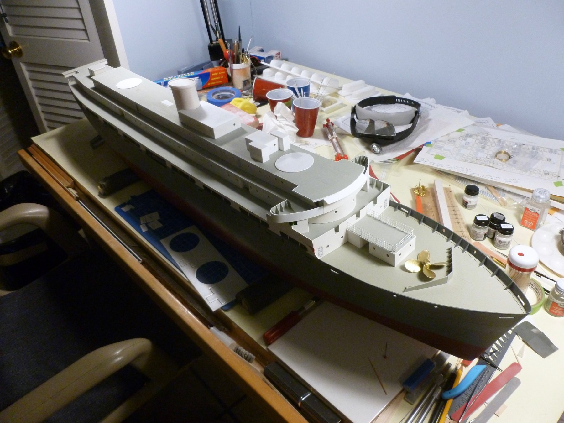
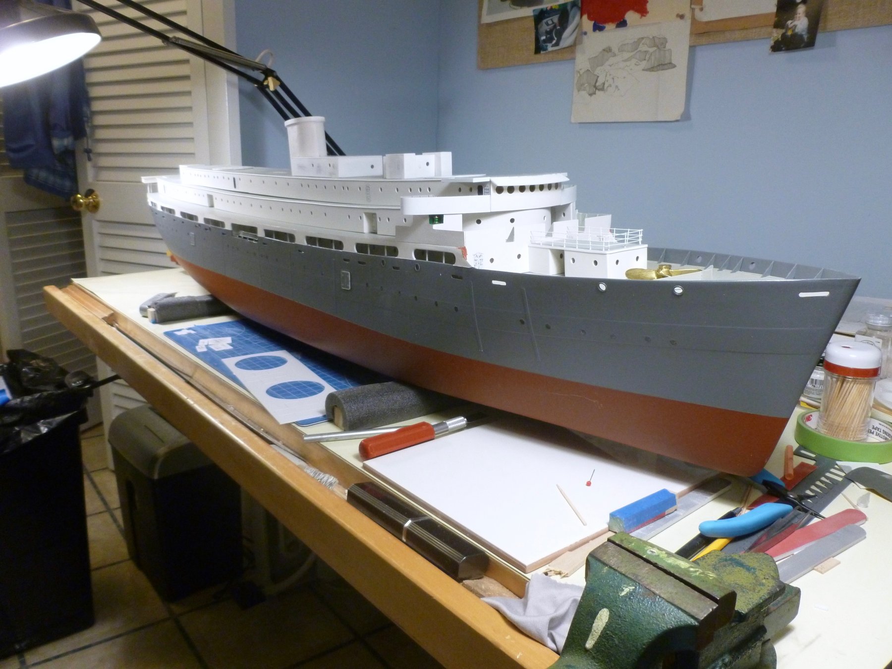
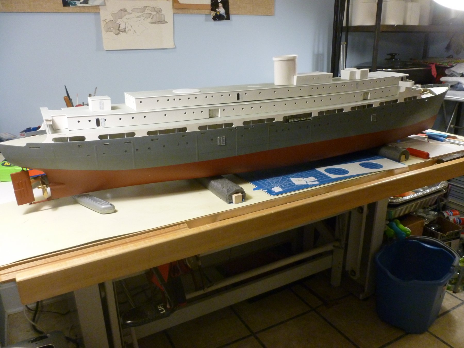
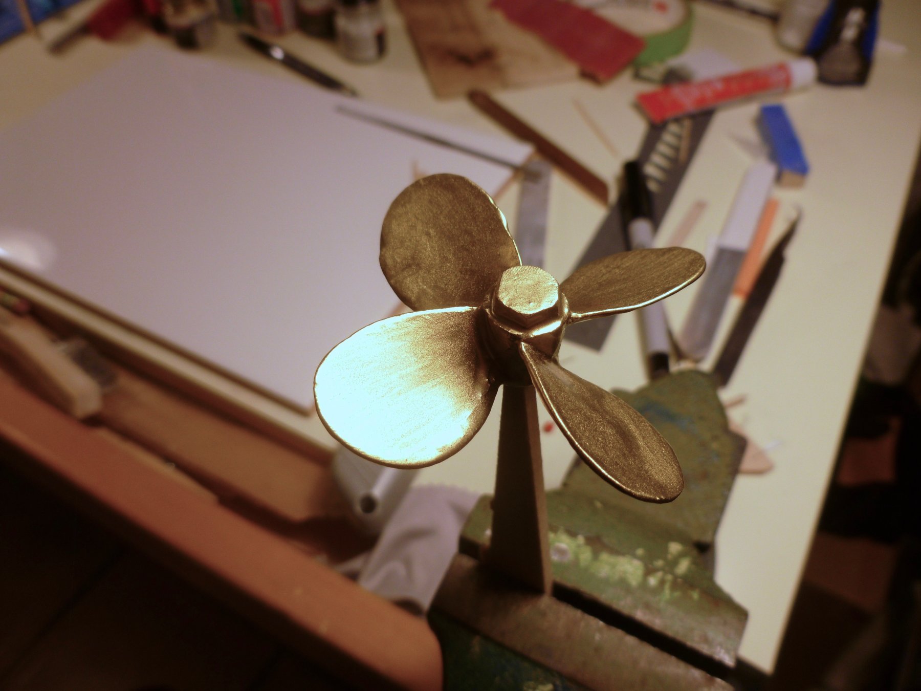
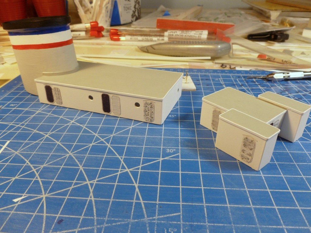
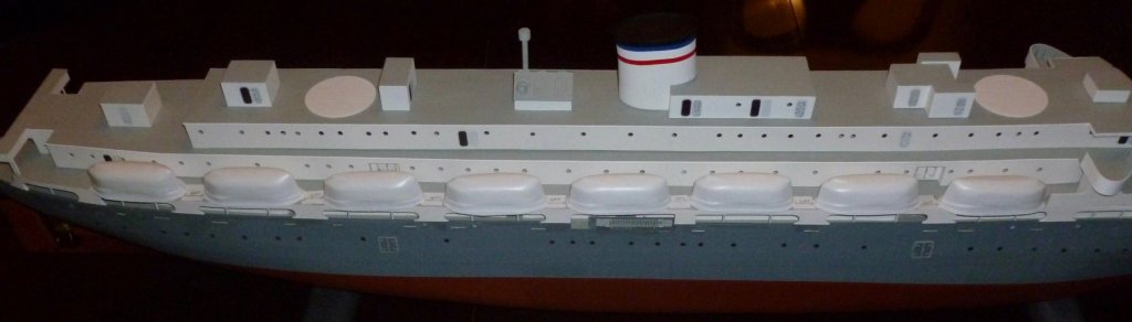
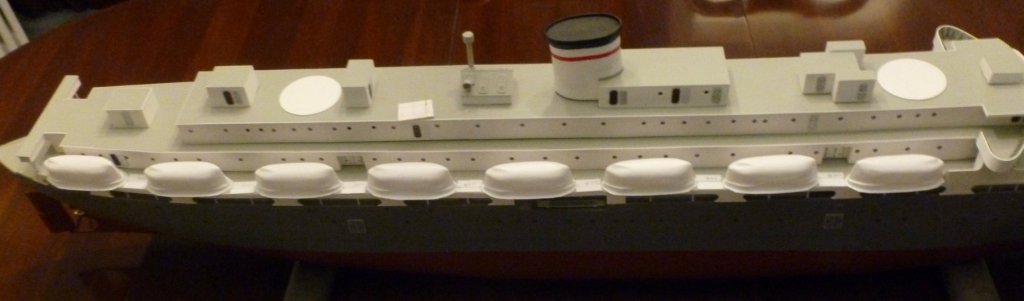
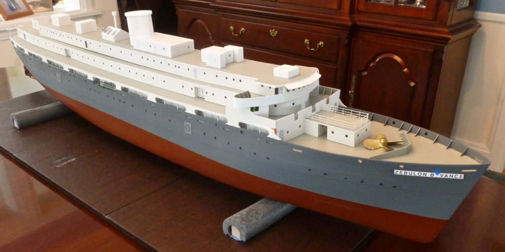
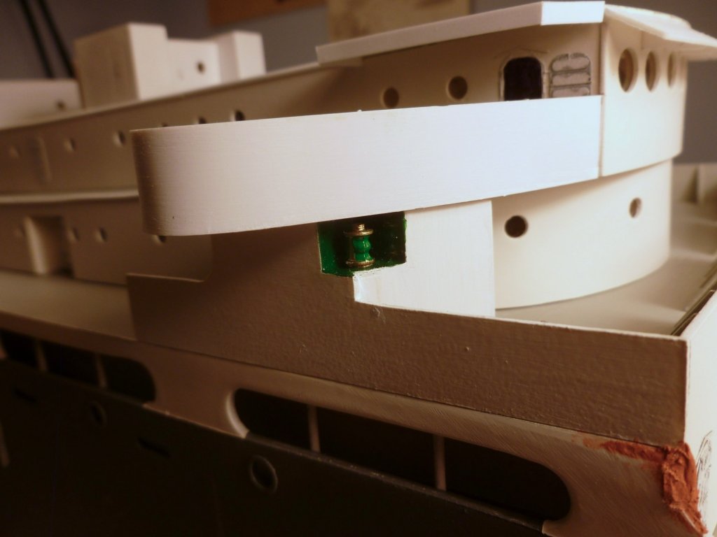
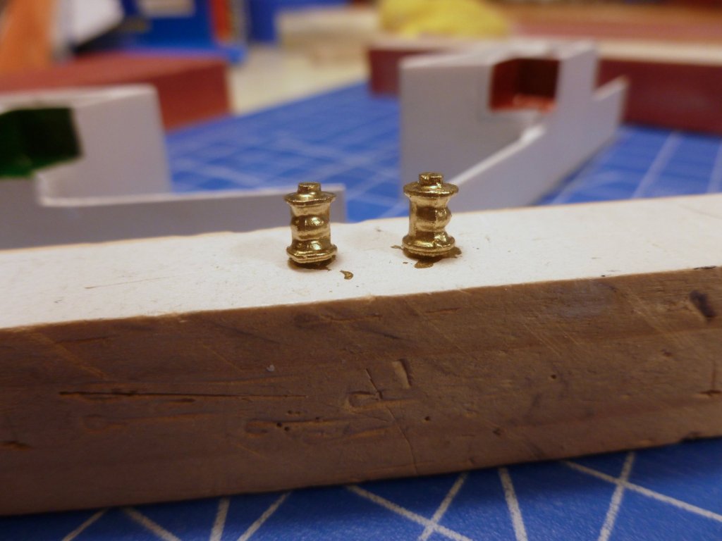
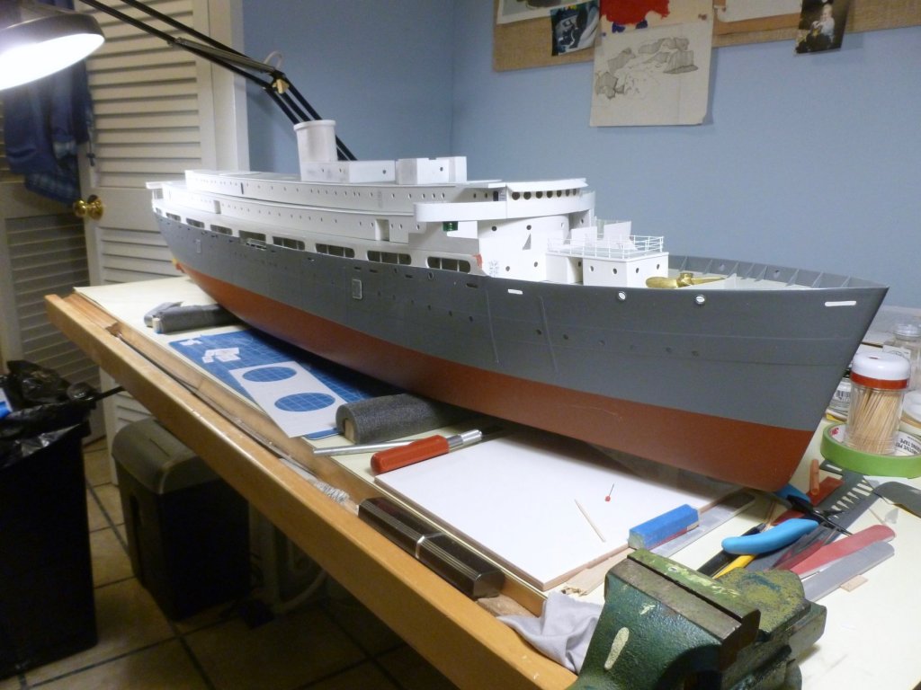
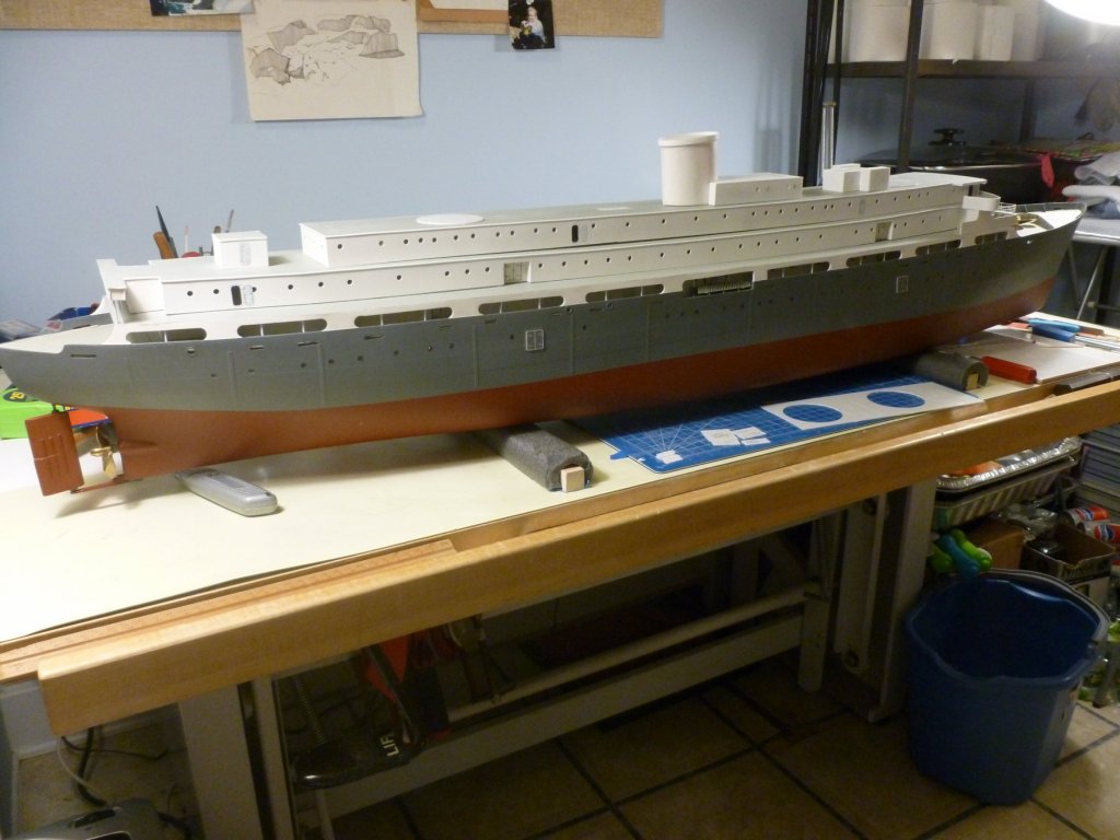
To those who gave likes, thank you and thanks for stopping by. Steve Decks are painted. The half round edging work was a bit fiddly at the aft bridge deck. Thankfully I had just enough - about an inch to spare - to finish the perimeter of both decks. I cleaned up the navigation lights and gave them a coat of brass paint before adding color for the lenses. I mixed a little black with the green and red at the nav light recesses to tone down the look. Still needs dullcote, but the navigation light housing assemblies are now glued in place. I'm working on the oops at the forward end of the join. The promenade fiberglass was fat in this area, and the curved forward end of the promenade wall didn't quite align with the forward corner of the nav light assembly. After the schmooze is smoothed we'll see how it looks. The drawings and build photos show a spare prop mounted on the foredeck. Since I purchased a real brass prop for sailing I used the kit metal prop for the spare, painted brass. I think it needs dullcote too. I anchored it with a short wood peg set in a shallow recess in the deck. Would the prop have been covered in canvas, or tied down in any way? The funnel comes in two vac-formed pieces that must be cut from the sheet, trimmed and sanded. Tabs must be added to the inside of one piece to help align with the other piece, but at the curved areas the tabs seemed to get in the way, with the end result being a need for auto glazing putty to fill and smooth out the joints and unintended overlaps. The completed funnel is then fitted to a recess in the radio room after much sanding to match curve to curve. The joint will get a piece of trim. The top deck is still not glued to the bridge deck, hence the gap. An overview of progress to date. It's a challenge to get all the ship in a photo, but the strongest light is in the narrowest room. Most everything is still loose and in need of paint. Besides the funnel/radio room, the top deck work so far includes the lift machinery room with a locker at each side. Below are a few more views. The circles are raised pads that had red crosses during hospital use. I’m assuming the quickie conversion to personnel carrier left the pads but painted out the crosses. There will be several more structures aft of the funnel, and a forward compass platform directly above the bridge.


- 446 replies
-
- 6
-
-
- zebulon b vance
- deans marine
- (and 3 more)
-
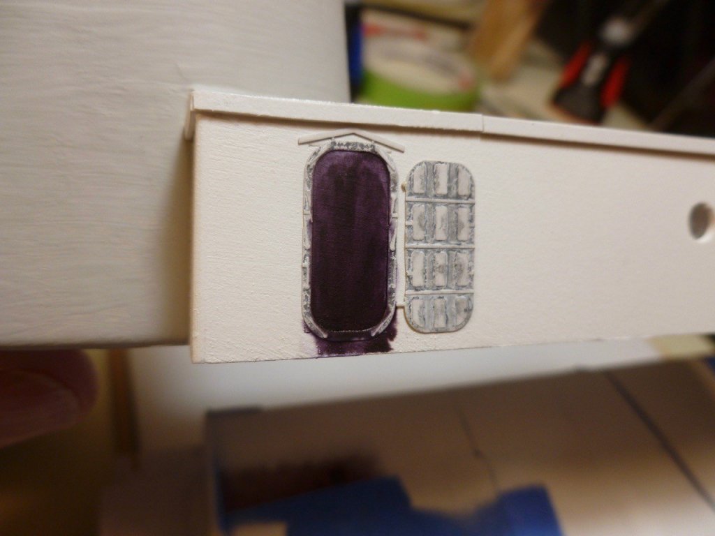
To those who gave likes, thank you and thanks for stopping by. Steve I added some simple brackets for the sunshade. The bronze look to the door opening is a light reflection on the black surface. A photo of the ship showed the edge of the extended top deck over the bridge doors to be deeper than just the thickness of the top deck so I'm adding a fascia around the edge. The bridge and top decks are painted gray. During the painting I managed to drip a large blob down the side of the cabin wall, even extending into a porthole. Fortunately some quick work with thinner cleaned up the mess. I’m debating whether to paint the sunshade topside to match the deck color, or white to match the cabin walls. The sunshade underside and brackets will be white. The half round trim thqt I pre-painted white will wrap the bridge and top decks.

- 446 replies
-
- 6
-
-
- zebulon b vance
- deans marine
- (and 3 more)
-
Your build shows very elegantly how the kit can be improved upon. Congratulations on such fine work. Sorry to hear about your knee, but there is light at the end of the cast. I was run over by a toboggan years ago (its a long story) and I know all about hobbling in a cast and brace while a knee heals. But in the end the aggravation was well worth it - 34 years later the knee still works. Steve
-
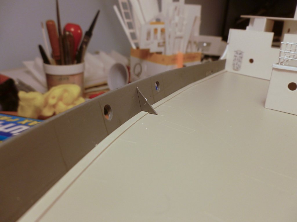
To those who gave likes, thank you and thanks for stopping by. Kevin, thanks for the roof leak sympathy. It must have done something because the drip has temporarily subsided. I looked for plans but was unsuccessful, at least without traveling 6 hours to check some unknown drawings near the National Capital. The Vance made home in at least three shipyards during its short career, starting with its original construction as a Liberty ship in an extinct North Carolina shipyard, to it’s conversion to a hospital ship in Boston and finally to its quicky retrofit in Brooklyn for war bride use. When I found the kit of its sister ship St. Olaf I figured I was home free and stopped looking. But I see from your build that detailed plans may be out there if you know where to look. Carl, thanks for your compliment. I think the huge expanse of white walls tends to minimize the darkness of the door highlights. Steve During the requisite mulling over on whether to attack the oversized wing dodger braces, I stood up a spare triangle to see how much effort would be involved if I tried to pare it down vertically. With a new chisel blade in the large X-acto I pushed down and was able to cleave the toe (actually a good part of its lower leg) off. Not too much effort and it looked doable on deck. Then I realized I could use the test piece as a template by tweezering it against each brace. And it worked! There’s a little chiseling and sanding to smooth out the deck, and painting for the deck and dodgers, but the little sailors can take comfort that the trip hazard is removed but they still have something to hold onto😊 On a roll now, I installed the breakwater. Not wanting to encounter the same size problem I decided to trim back the triangles so the base legs were all the same length and the vertical legs would follow the top slope. Once I got the cut order figured out the braces were fitted without incident.
- 446 replies
-
- 7
-
-
- zebulon b vance
- deans marine
- (and 3 more)
-
Kevin, thank you for your kind comments. I've only been a member for a year or so and I'm catching up on other builds. When I clicked on your HMS Fife I was blown away. Simply magnificent. Makes the Vance look like a rowboat. Bill, the size of the dodger/spray shield braces surprised me too. Since I'm basically ignorant of how the real ships were detailed, and since this is only my second build, I tend to rely on the instructions and laser cut pieces to be accurate. The instructions are limited to a single line drawing with no scale, showing a triangle to be placed inside. The installed triangles were the smallest ones in the carrier sheet and the long leg matched the height of the spray shield. Looking back through the various prototype build photos included with the kit, I found that the triangles were smaller in one picture, in another picture they were vertical strips with a short taper at the top, and in a third photo they were straight vertical strips with no taper. I guess the choice is to leave the tripping hazard, although I thought it had a nice, if non-functional pattern to it; try trimming back some of the horizontal leg, or rip the whole thing out and do-over. This news is coming on the same day that the admiral called to tell me our formerly pristine ceiling in the TV room was dripping due to a roof leak after a driving rain on top of the 14 inches of snow that fell over the weekend. I may take the easy way out, but I'll have to mull it over and thank you for bringing it to my attention. To everyone else, thanks for all the likes, and thanks for stopping by. Steve
- 446 replies
-
- 3
-
-
- zebulon b vance
- deans marine
- (and 3 more)
-
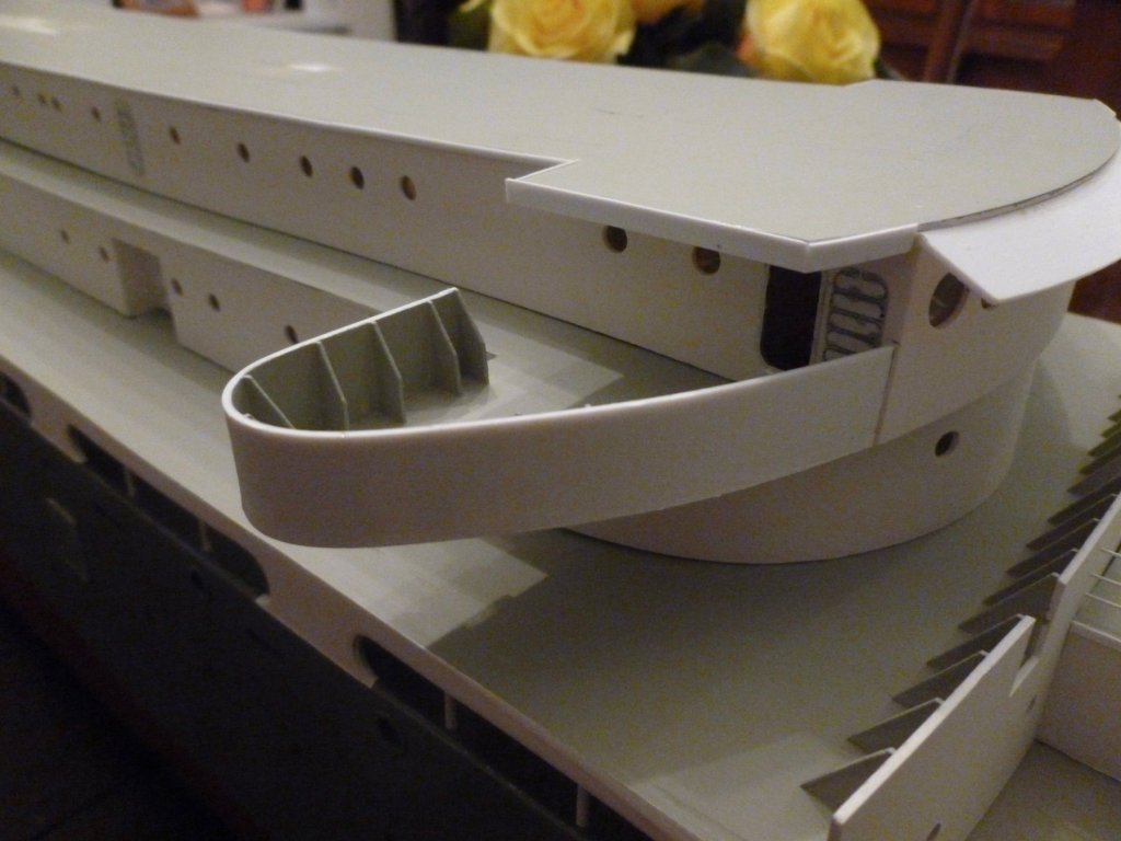
To those who gave likes, thank you and thanks for stopping by. Well Lou, it looks like your pre-emptive and massive porthole strike created so much shock and awe that no one else is coming forward. You are the porthole king. Carl, I’ll be piercing portholes a while longer. Hang in there, and thanks for staying around. Roger, thank you for your very kind comment. If I had 10% of the skill of the real scratch builders I’d be very happy indeed. Bill, thank you for your suggestions. Strips for glazing could be a challenge in this build because of all the support angles, door recesses, bulkhead stiffeners and such. The light block is a good idea but it would have to be coordinated with the removable deck units and installed in such a way that it would have stiffness and structure when the decks were out. Perhaps not on this build but I will keep it in mind for future work. Almost portholed myself into a corner. After using up the kit sheet, I finished the glazing with the acetate sheet from the art supply store. The kit sheet had a colored protector sheet to peel off one side. When I started with the new sheet it didn’t occur to me that it might have a protector sheet on both sides. I was about four portholes into it when I looked closely at the sheet edge and noticed the telltale extra lines on either side. Sure enough, when I poked at one of the installed pieces of new sheet it popped right off since the CA didn’t adhere to the cover. The good news was that the other three popped right off too. After removing both protector sheets the remaining glazing stuck well and was finished up in sort of short order. I started on the wing dodgers - tricky bits that follow a tight compound curve, must be held tight to the bridge wall, and must be glued flush with the bottom edge of the bridge deck. After wrestling with the first one I realized that if I ran hot water over the second one it became very flexible. So I bent it into a tight curve, taped it and let it sit overnight. The forming made it easier to fit and progressively glue the second dodger. Using my experience with the main foredeck bulwarks, the dodger bulwarks went smoothly. I found that if the deck to “wall” is not perfectly 90 degrees, a tiny angled slice across the bottom of the bulwark triangle puts the two legs flush to the deck and wall. A view of progress on the dodgers and doors. Rightly or wrongly, I’m considering the double doors into the personnel cabin areas to be of a different type than the watertight doors at the utility and control rooms. Along with the dodger bulwarks I had to add a few at the forward end wall of the boat deck. I installed the sunshade over the bridge portholes after filing a small groove along the bridge wall to top deck intersection. If anyone has any suggestions for supports under the sunshade, or blocking to strengthen the joint please chime in. The top two decks are getting closer to gluing together, after more painting is done. I had to add some additional strips along the underside of the top deck to align the glue surface with the bottom edge of the bridge cabin walls. The joint between the top and bridge decks needs to be strong since they are removed and replaced as a unit when servicing the RC bits.


- 446 replies
-
- 7
-
-
- zebulon b vance
- deans marine
- (and 3 more)
-
A lot of hard work to date and very well done. A very rich looking model. Steve
- 162 replies
-
- 1
-
-
- america
- BlueJacket Shipcrafters
- (and 1 more)
-
Lou: Thank you for the compliment and your suggestions. 800 p😲rtholes at 1/350 - I'm humbled and will complain no more about my measly 300. I wondered if floating a number might trigger a porthole competition, and will scan the horizon for any contenders. Likers, you're on the spot! Steve
- 446 replies
-
- 3
-
-
- zebulon b vance
- deans marine
- (and 3 more)
-
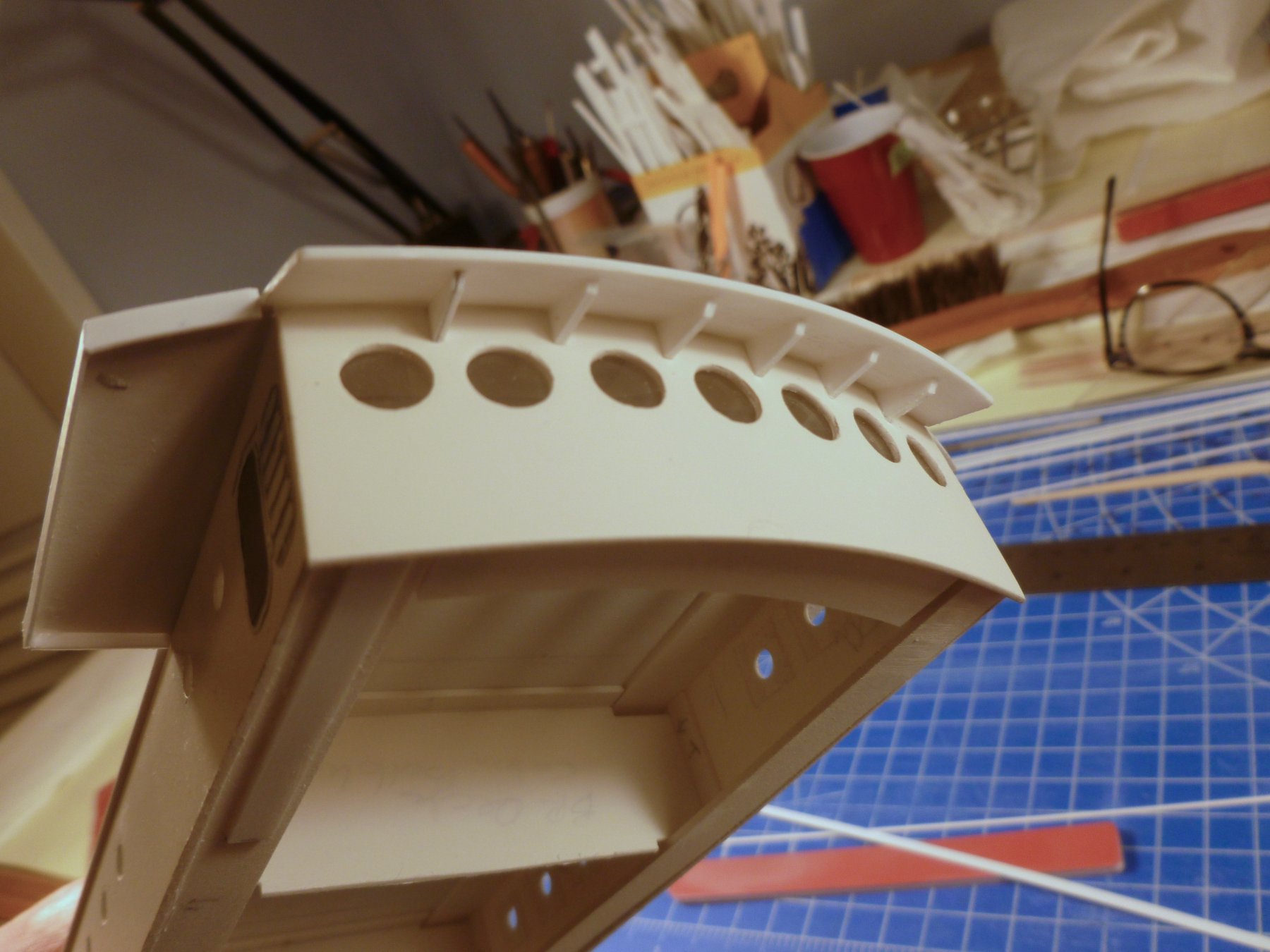
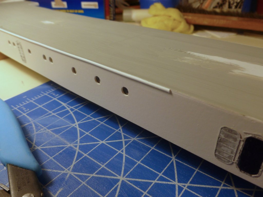
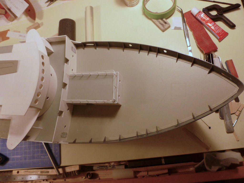
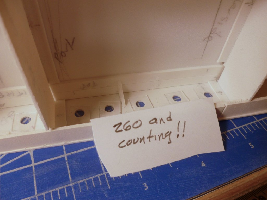
To those who gave likes, thank you and thanks for stopping by. Steve Much time was spent sanding the bottoms of the bridge deck and top deck walls to make the long runs as tight as I could. I also painted the walls on both decks. Unfortunately it doesn’t make much of a photo change from the white styrene. I’m reaching the saturation point with portholes. After carefully drilling them (I think there will be upwards of 300 by the time I’m finished) they have to be glazed from the inside with 10 x 12 mm bits of hand cut acrylic. Not very difficult, but really boring. The good news is I’m within shooting distance of the end. The bad news is I will run short with the sheet from the kit and I had to buy an 18" x 24" piece of thick acetate at the local art supply store so I'd have it to work on over the weekend while the blizzard comes through the area. I'll have a lifetime supply for any other glazing-intense ships. To have a few port-holeless evenings I worked on various bits and pieces. The navigation light housings/rooms are almost finished (only one porthole each plus a door). There is a little cast light for each one and I’ve seen some pics, not of this ship, where the recess is painted to match the nav light color. Is it green starboard, red port, and should I even paint the recesses? The radio room is built, with trim to match the main deck forward A/C room. Still needs gluing in place and a railing along the walls. I think I need them for most other walls too if that’s appropriate. The bridge deck and top deck still need their gray paint. A view of the three doors under the bridge deck aft bridge. The main fore and aft decks were not quite tight to the hull, even after wrapping the whole shebang with tape while the glue dried. I’ve added a small edge trim (0.5 x 3.2 mm) to the fore deck and am working on the other end. After setting the first edge trim I experimented with the bulwarks which come as laser cut triangles, but need fettling, first because of the edge trim and second to align with the changing slope of the hull. The fore deck bulwarks are finished. It seems a bit odd that they are not evenly spaced. The lasered layout lines show some boxes in the gaps. Is this how a ship would actually be built?

- 446 replies
-
- 8
-
-
- zebulon b vance
- deans marine
- (and 3 more)
-
To all who gave likes, thank you and thanks for stopping by. Carl, thanks for the bending tip. I was so concerned about whether I could bend the assembly without kinking it that I lost focus on the fact that the bending angle needs to be in a very specific plane, vertically as well as horizontally. From the boat deck up, the strengthening triangles are located at the roof/wall intersection. The bottom of each wall is anchored by the continuous curb running around the deck (here I am! here I am! watch me run! - okay - punchy time over; curb your curb). Apart from the forward bridge area, which has large triangles but is experiencing no placement gaps, the triangles are very small and come nowhere close to the curb. I looked at the aft cabin gap again tonight. I'm beginning to think it is a function of the sheer slope that is built into the top and bottom of every laser cut sidewall strip. While working upside down, and while attaching the wall top to the underside of the next deck above, the instructions call for placing a dowel (I use a piece of plastic pipe) at about mid-point under the inverted deck, to maintain the upside down sheer. This method is an approximation at best of the deck sheer and as you go aft the gradual increase in sheer slope may not match between the wall strips and the deck. Some judicious sanding all around the cabin wall bottom edges may be needed to help close the gap. I don't want to do too much since most of the walls maintain a tight joint. I thought the gap might go away when the bridge and top decks are glued together and weighted down to dry, but when I added some weight to the center of the top deck (no glue), the aft cabin gap didn't improve, but the forward bridge area started showing a gap where none existed before! Perhaps I have built a little see-saw into parts of the cabin sidewalls. The investigation continues.
- 446 replies
-
- 4
-
-
- zebulon b vance
- deans marine
- (and 3 more)
-
Almost forgot, a belated thank you to reigels for sharing some photos (sorry Scott). Steve
- 446 replies
-
- 2
-
-
- zebulon b vance
- deans marine
- (and 3 more)
-
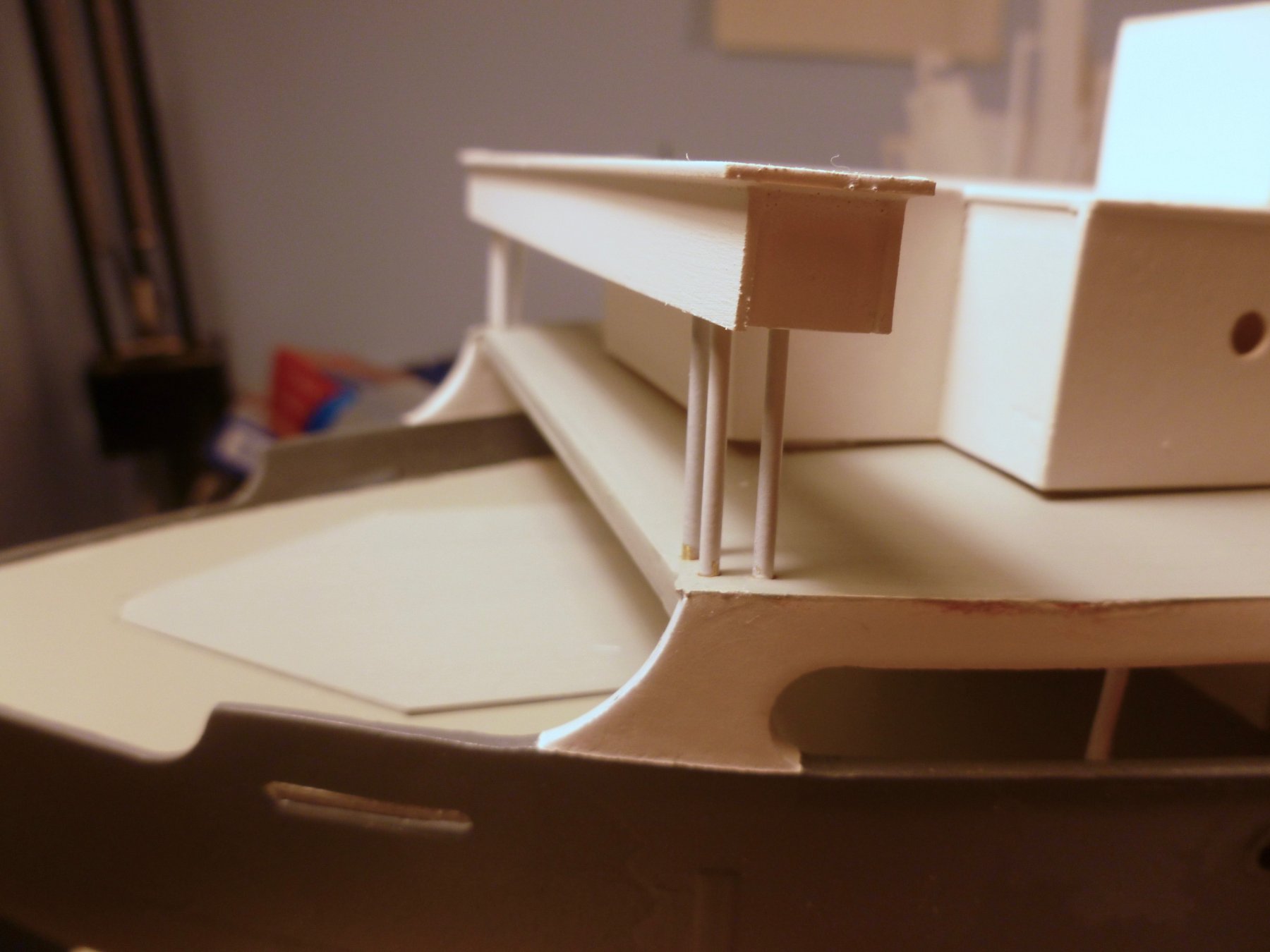
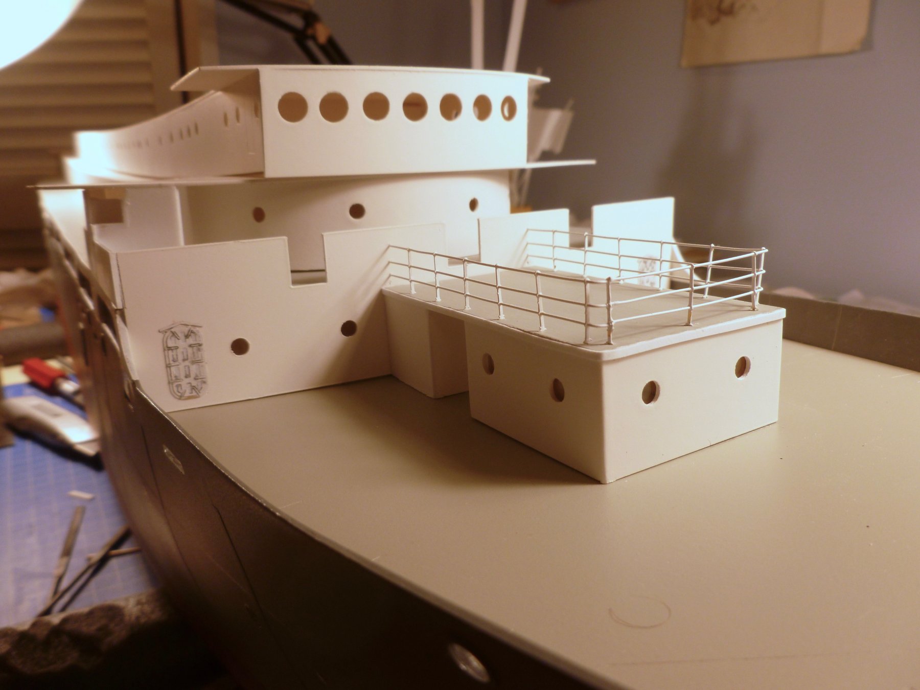
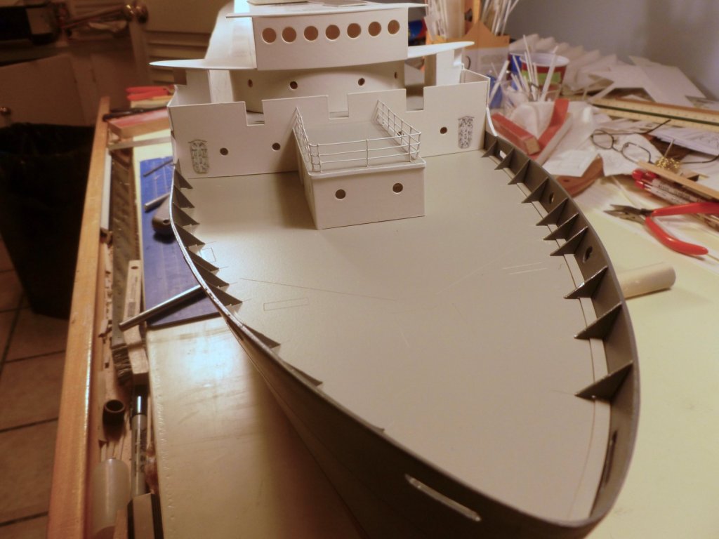
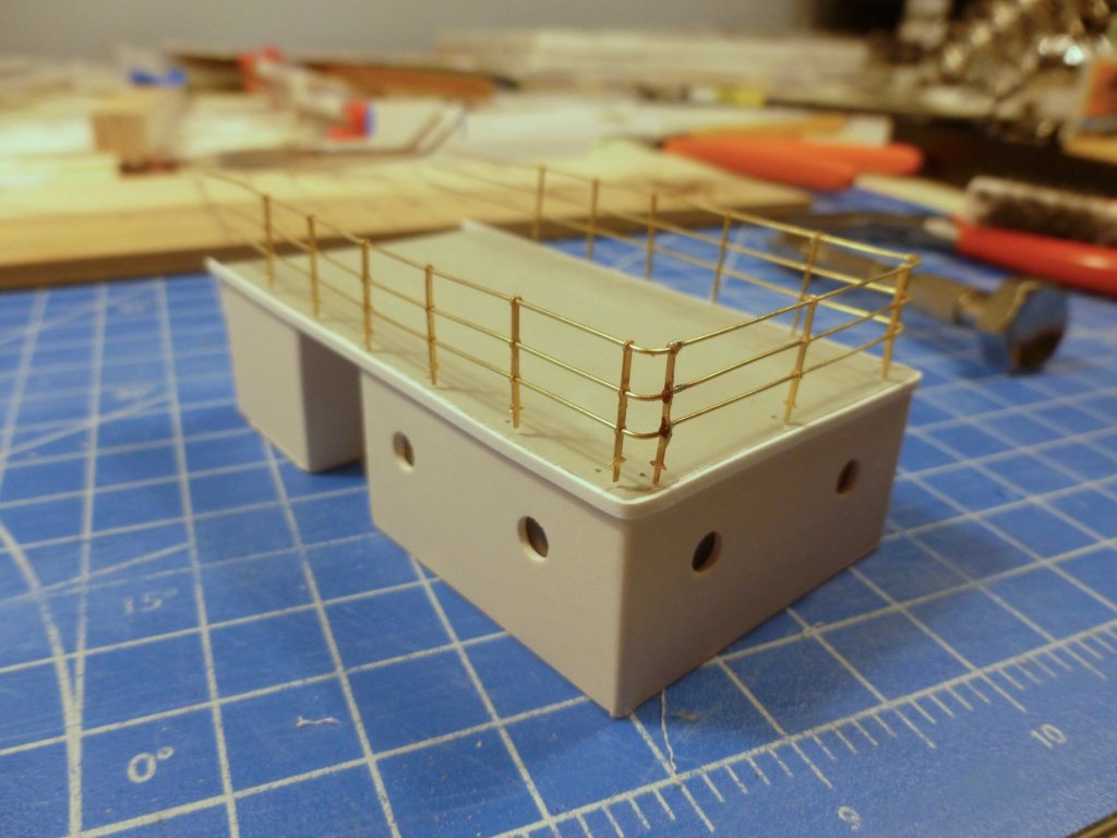
To those who gave likes, thank you and thanks for stopping by. Carl, ignorance is bliss when it comes to my next problem, but I do see the construction of 16 vac-formed life boats with their attendant davits as a good bliss destroyer. I noticed that the aft bridge posts were a bit willowy in plastic when they were not locked in place by the bridge, so I changed over to brass rod. After drilling the boat deck to receive the posts, and installing the posts into their top plates, the assembly became quite rigid, even when standing free. Now if I could figure out what is keeping the aft cabin from setting fully on the boat deck. The posts have some clearance at the top so I know it is not them. I sanded tight spots along the base of the side cabin walls and trimmed the mounting curbs but I still can’t get the aft cabin to set. I’m thinking it might be the joint between the aft wall of the main cabins and the side walls of the aft cabin. Of course, once the upper section is removed and replaced a few times for sailing, the joining area between cabins and boat deck will probably get out of whack anyway. The doors have been whitewashed to soften the grungy highlights. After much trepidation I finished the assembly of the air conditioning room roof railings. It’s a hybrid, with CA for most connections and solder where the two sections join at the right hand stanchion in the foreground. The railings dead end at the forward wall of the boat deck. To make a clean joint that would maintain the spacing between railings I marked drill holes using a stanchion with the base cut off, and taped in place on the wall. I left the railings long and started the final installation by pushing them through the wall holes. I set the stanchions in medium CA’d drill holes (I gave up on the idea of heat setting) and trimmed the excess railings at the inside of the wall after dabbing the wall penetrations with some thin CA. Painting consisted of an apple cider vinegar bath (it was all we had), soap and rinse cleanup, followed by BIN primer and flat white topcoat, both from rattle cans sprayed very lightly. I learned a lot with the first railing assembly, among other things that the corners need much attention to ensure everything is plumb and square. Corner bends were made after a section of railing was assembled, using a nail driven into a piece of wood for the radius, but I’m inclined to allow one stanchion to act as the corner support rather than trying to set two stanchions in different planes so close together.


- 446 replies
-
- 6
-
-
- zebulon b vance
- deans marine
- (and 3 more)
-
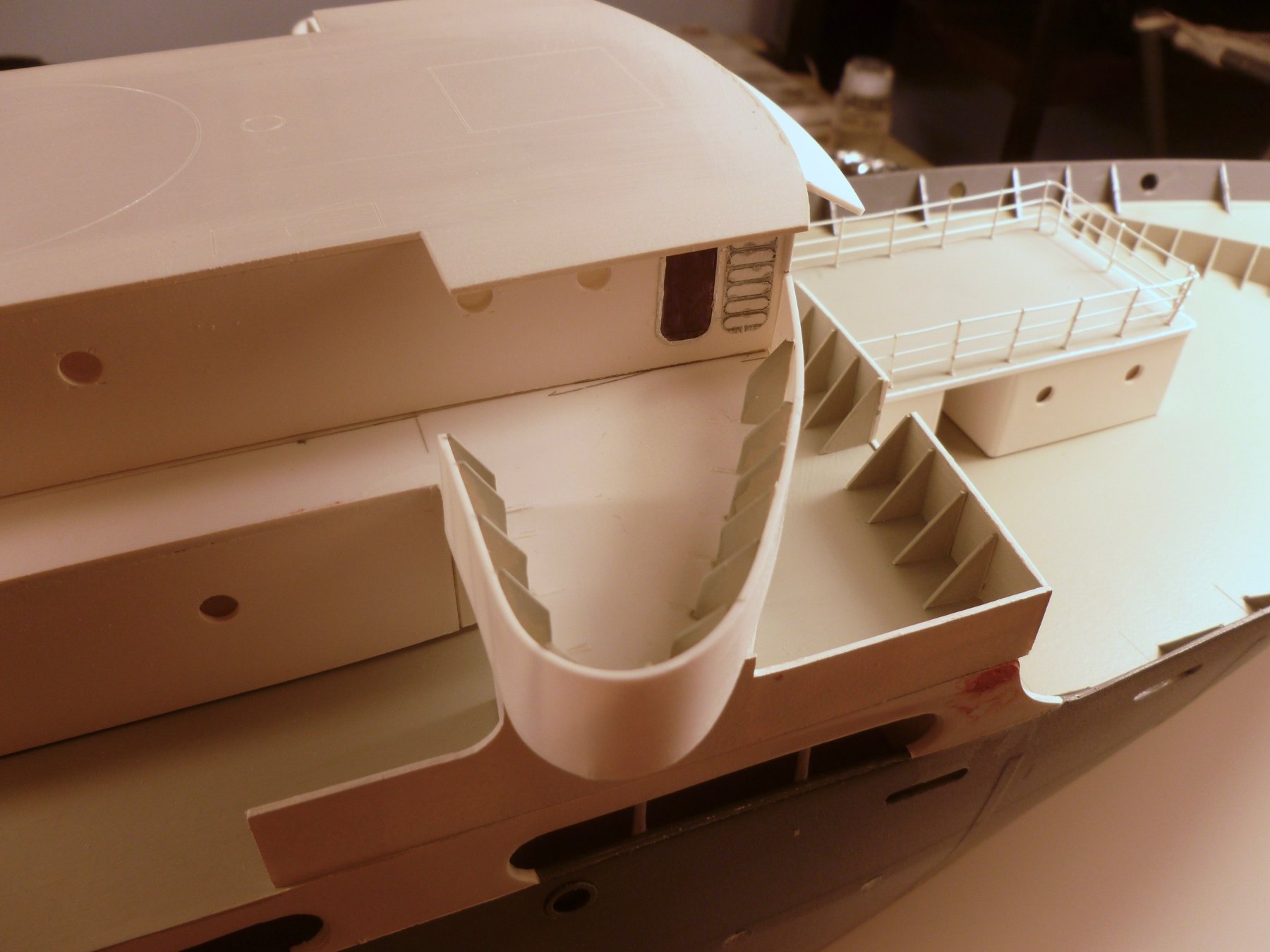
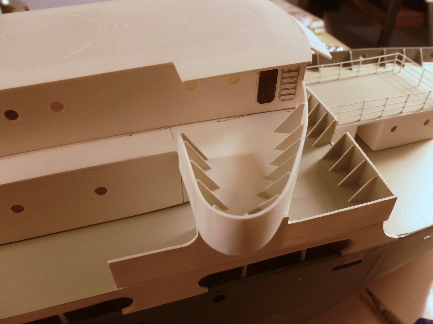
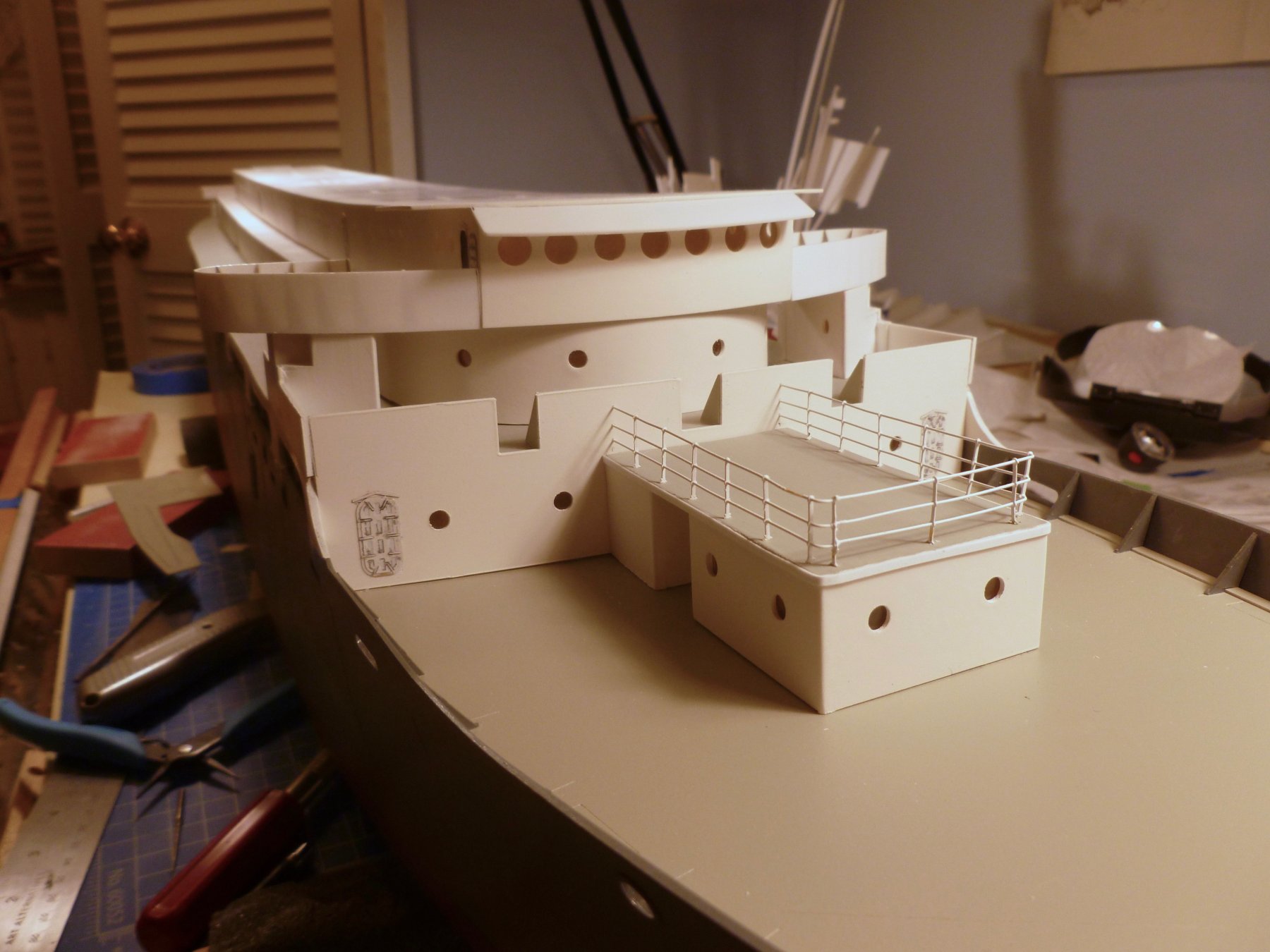
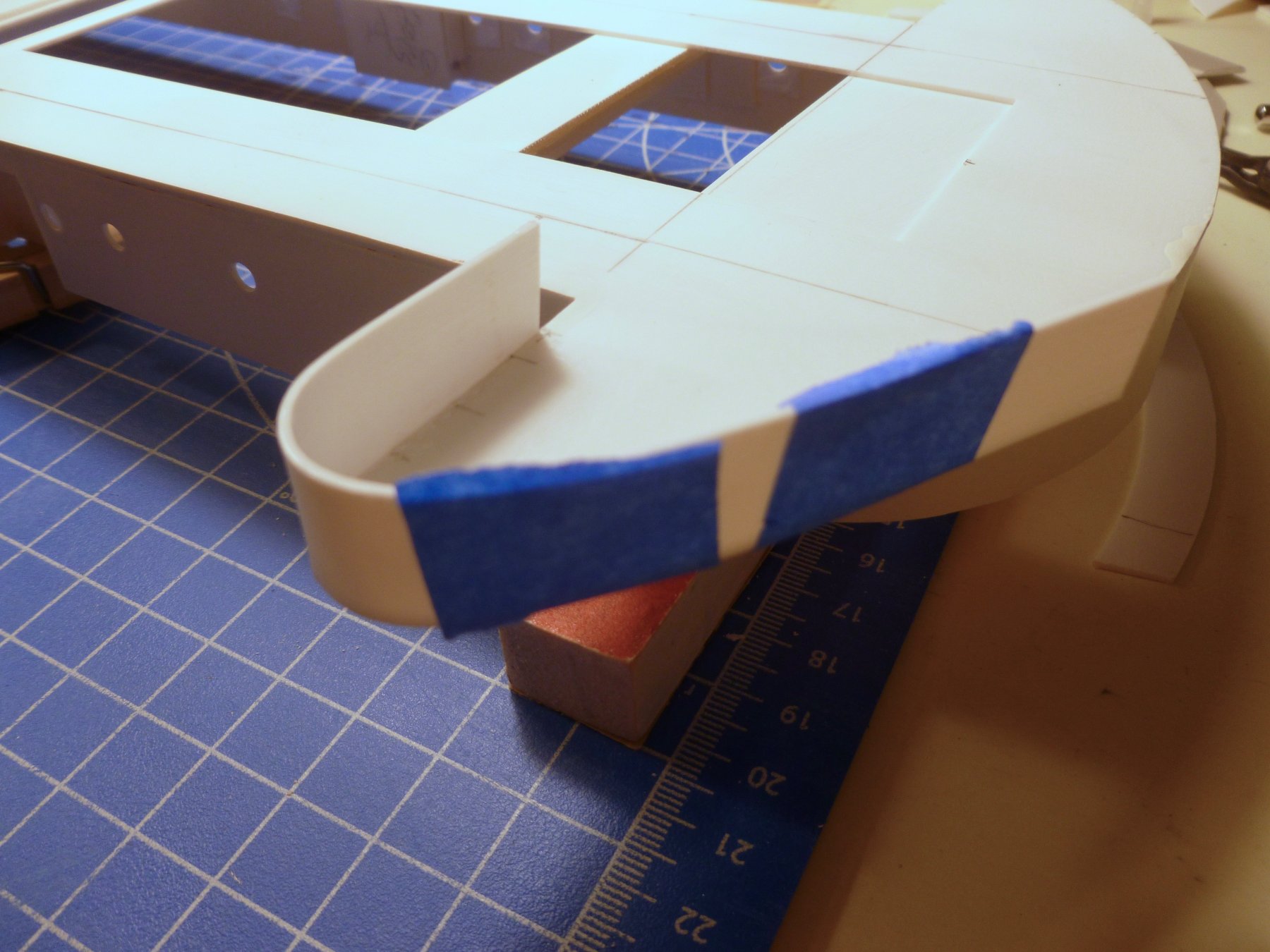
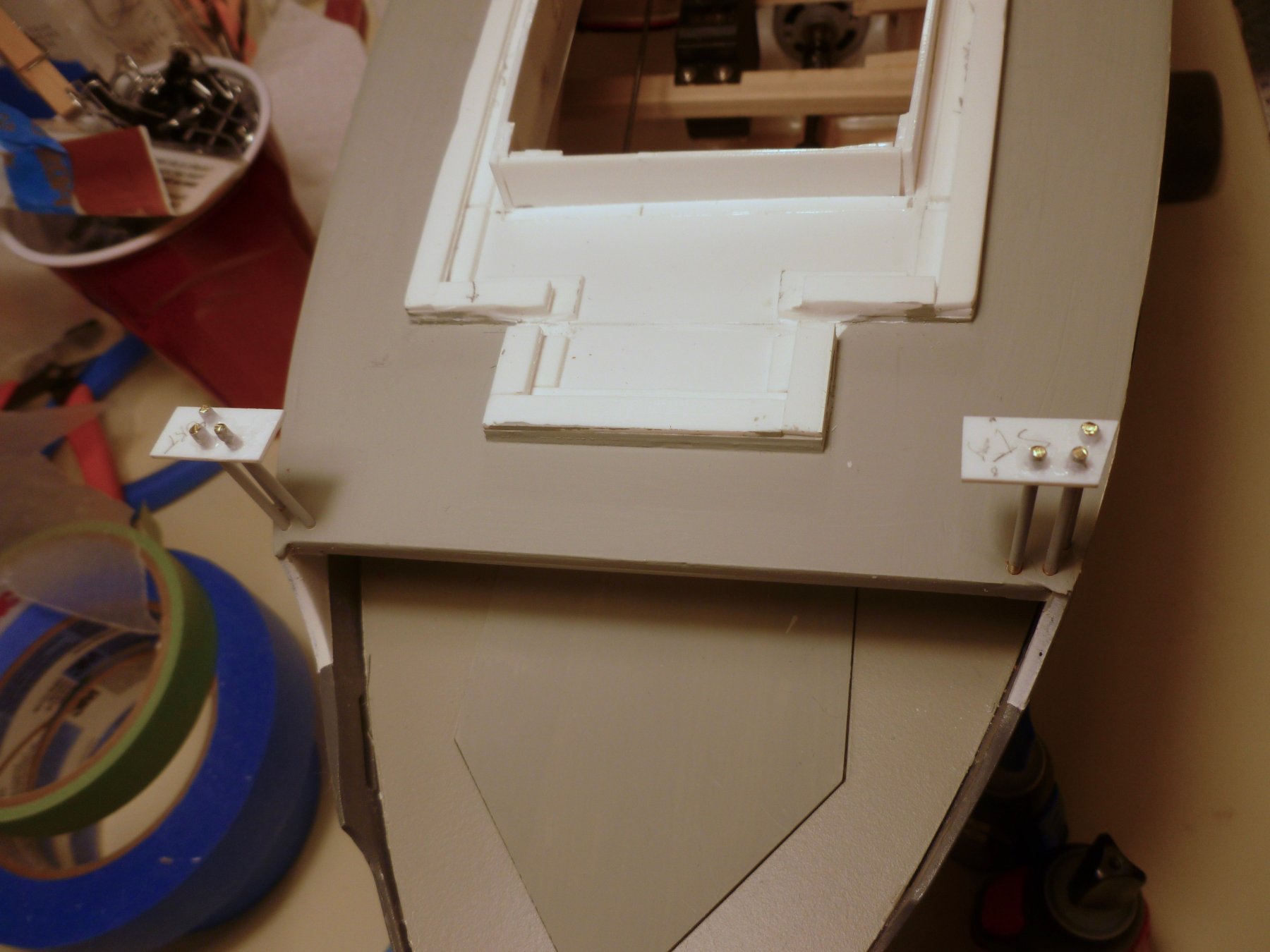
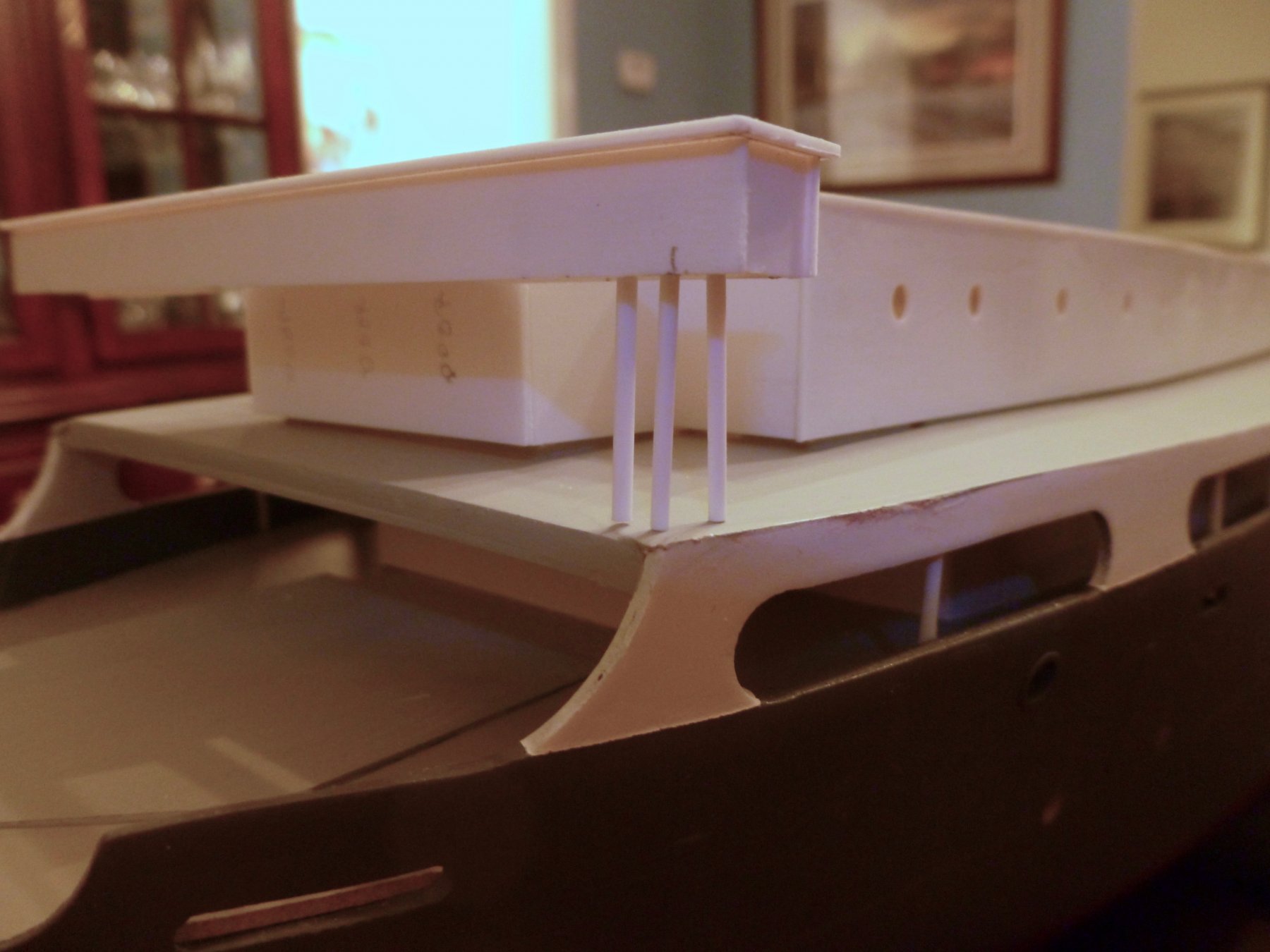
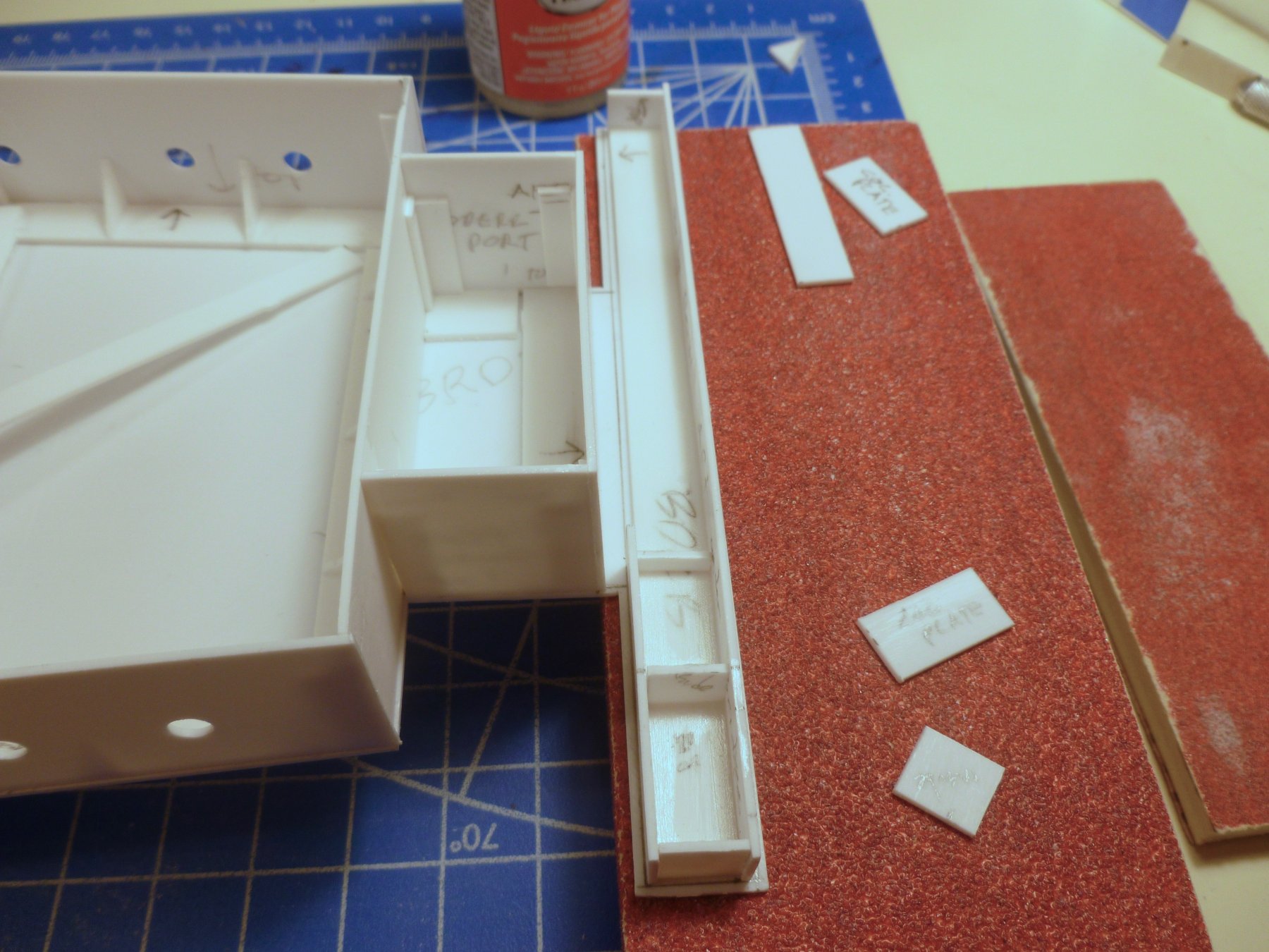
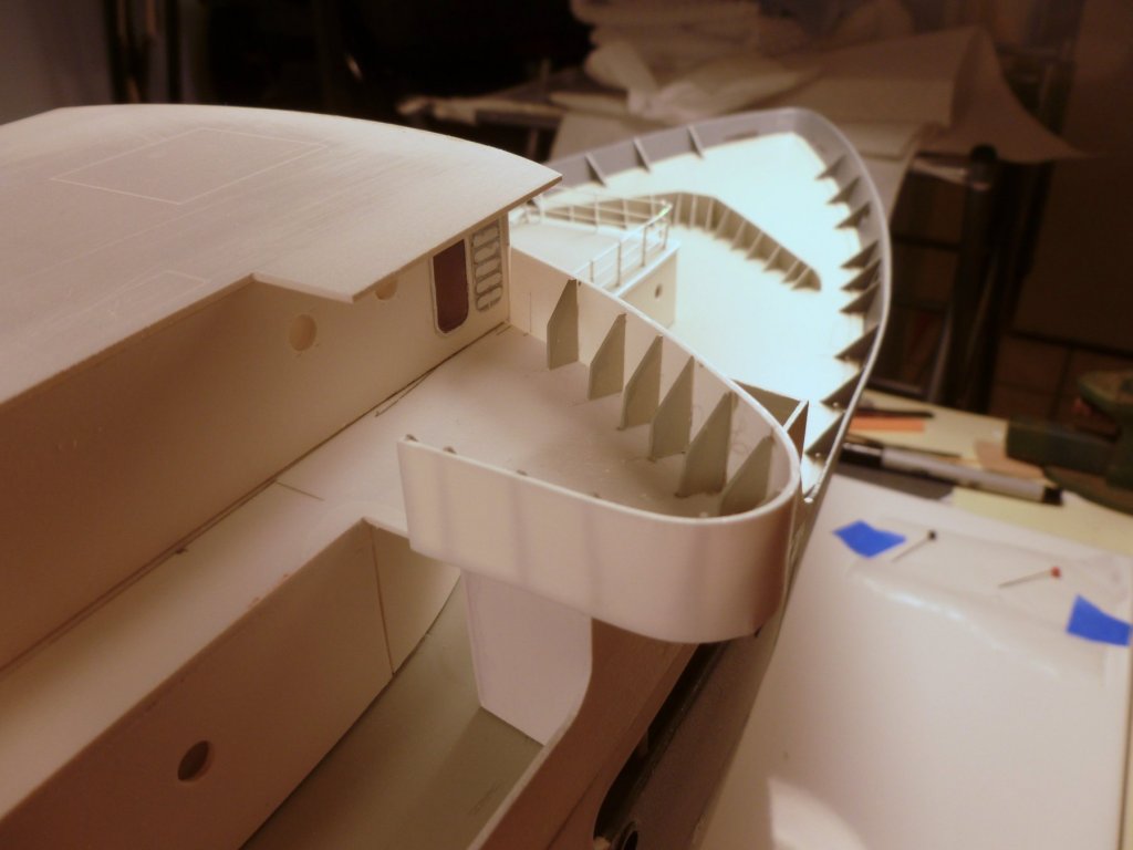
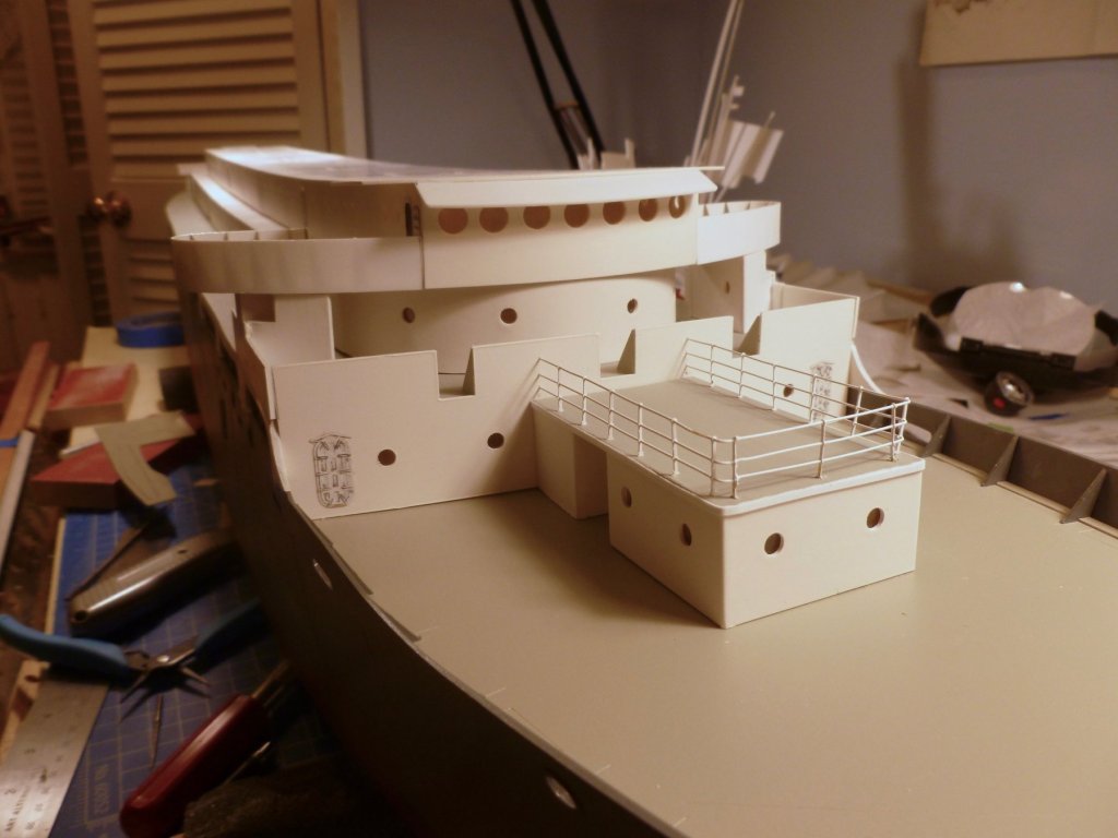
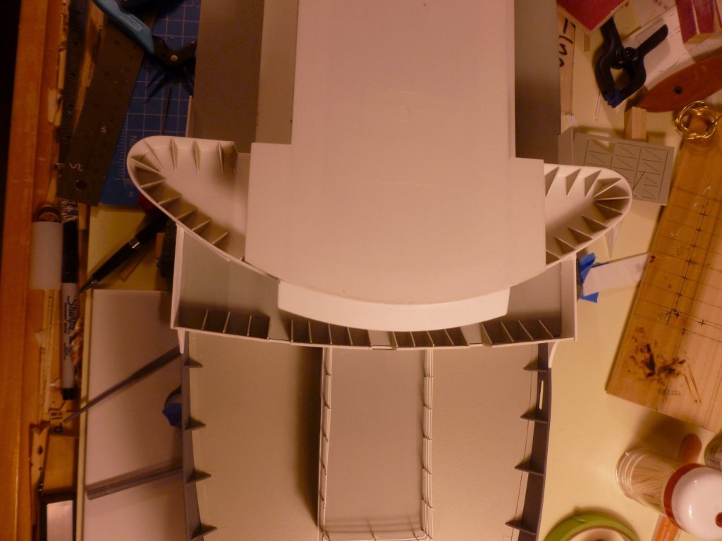
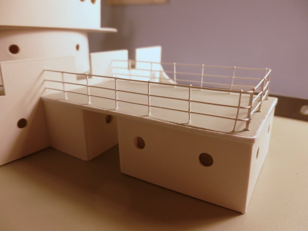
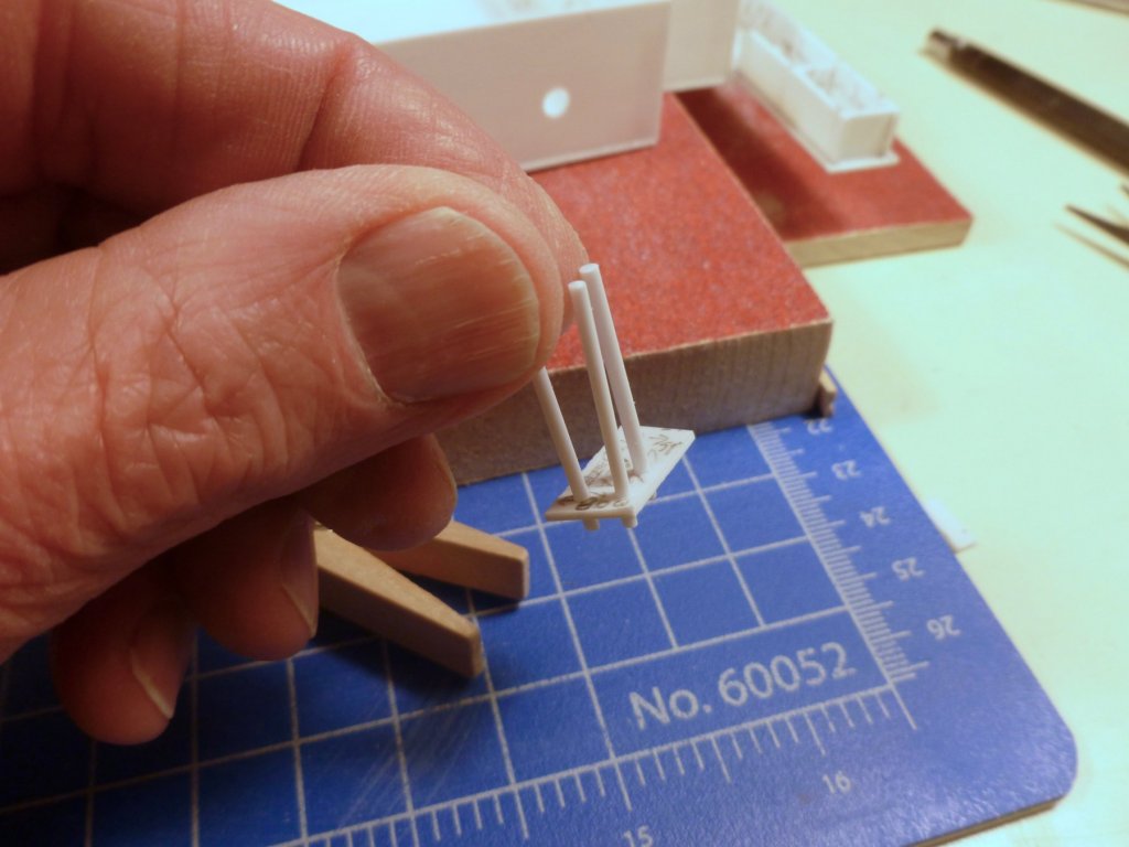
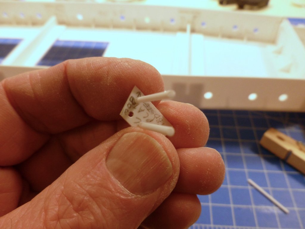
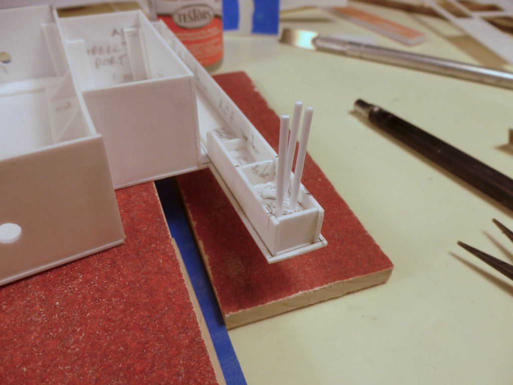
To those who gave likes, thank you and thanks for stopping by. For my long-timers, thanks for hanging in there. I truly appreciate your ongoing interest and support. Steve Part two of the aft bridge column story. For those arriving late, the issue is that photos show the aft bridge had columns down to the boat deck level, but there is no mention of them in the model instructions or model build photos. It appears they were left off because the bridge deck and everything above it must be removable to access the RC bits. The aft bridge looks odd with no visible means of support so I thought I would try to develop a way to have my column cake and eat it too. I started with constructing a fascia, or apron, around the underside of the aft bridge. I blocked off within the fascia to create a pocket at each end of the bridge. I placed the bridge deck on the ship and transferred the aft, port and starboard boat deck edges up to the bridge deck fascia. This established an alignment angle for cutting the column top plates that will fit into the pockets. I cut out the top plate for one of the fascia pockets and drilled three holes in it to receive columns. I will also use the top plate as a template for laying out the column holes that will be drilled into the boat deck. The idea is to anchor the columns solidly on the boat deck, but allow them to float within the bridge pocket. When the bridge deck is removed the columns and column top plates will stay behind. As the bridge deck is reinstalled the columns and top plates will slide into the bridge fascia pockets. The plastic columns (Evergreen) are 1/16” diameter (6” pipe columns) x 28 mm long. The actual dimension from the boat deck to the underside of the bridge fascia is 20 mm. 28 mm allows a small drilling distance to set and glue the columns into the boat deck, and allows the top plate to slide up and down a bit within the fascia pocket for final fitment, before gluing the plate to the column tops (but not to the fascia pocket). I test fit the column/top plate assembly into the fascia pocket. Then I reinstalled the bridge deck on the ship and wiggled the column/plate assembly into the pocket. Since the columns aren’t drilled into the boat deck yet they are holding the bridge deck (and boat deck cabins which are attached to it) slightly above the boat deck. Depending upon how deep I drill the boat deck holes I may need to trim the column tops a bit, but it looks promising as a way to have columns between the boat deck and bridge deck, but still allow the bridge deck to be removable.


- 446 replies
-
- 8
-
-
- zebulon b vance
- deans marine
- (and 3 more)
-
Carl, even with notes littering the parts I managed to install one aft wall upside down (downside up?). Fortunately I realized knee high portholes were inappropriate on a war bride ship, before the glue fully dried. The drill bit for the bridge portholes was 5/16". It works okay as long as the drill turns very slowly - I can watch each revolution.
- 446 replies
-
- 4
-
-
- zebulon b vance
- deans marine
- (and 3 more)
-
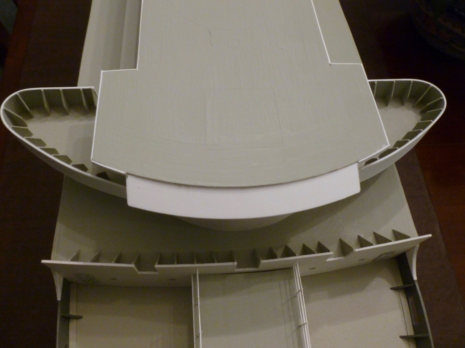
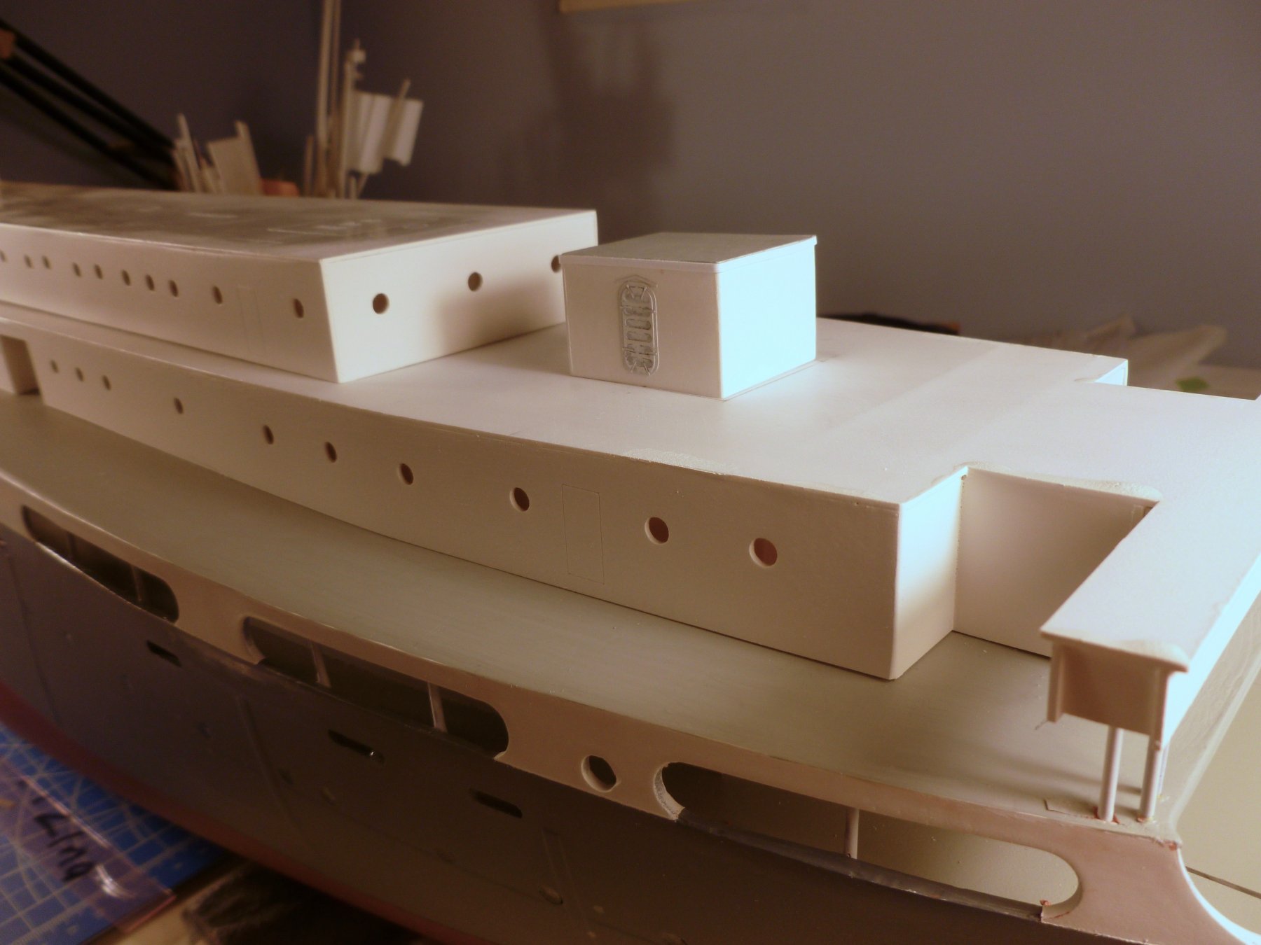
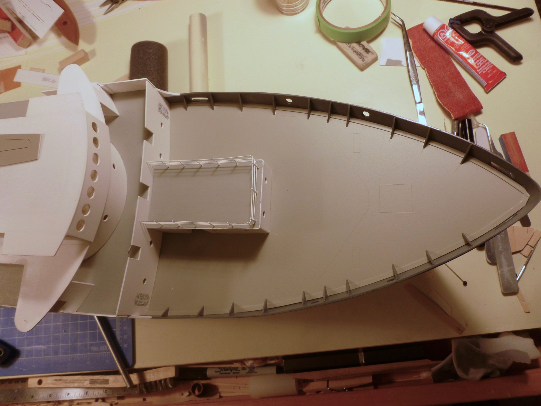
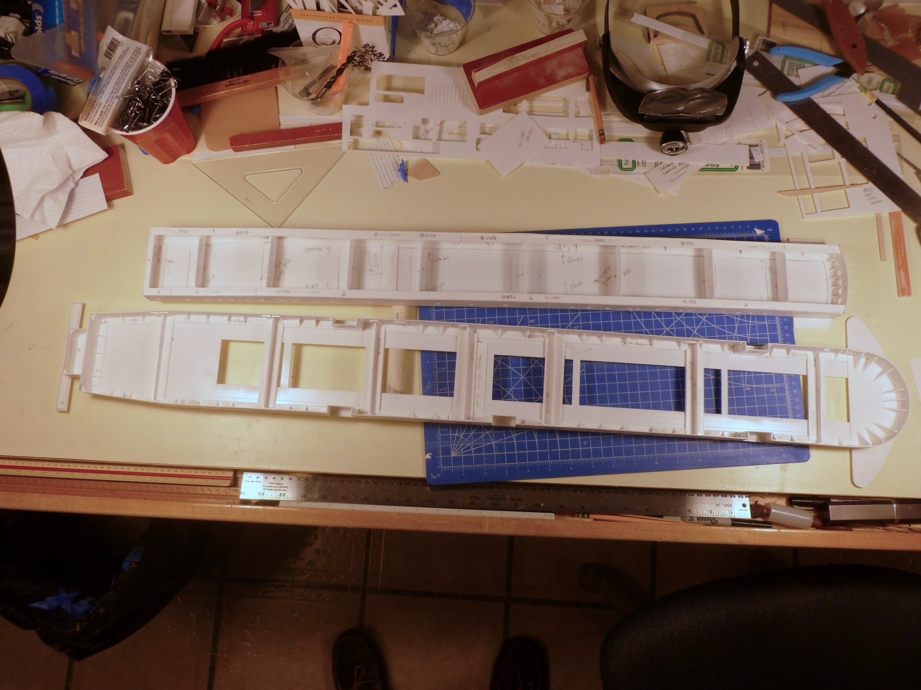
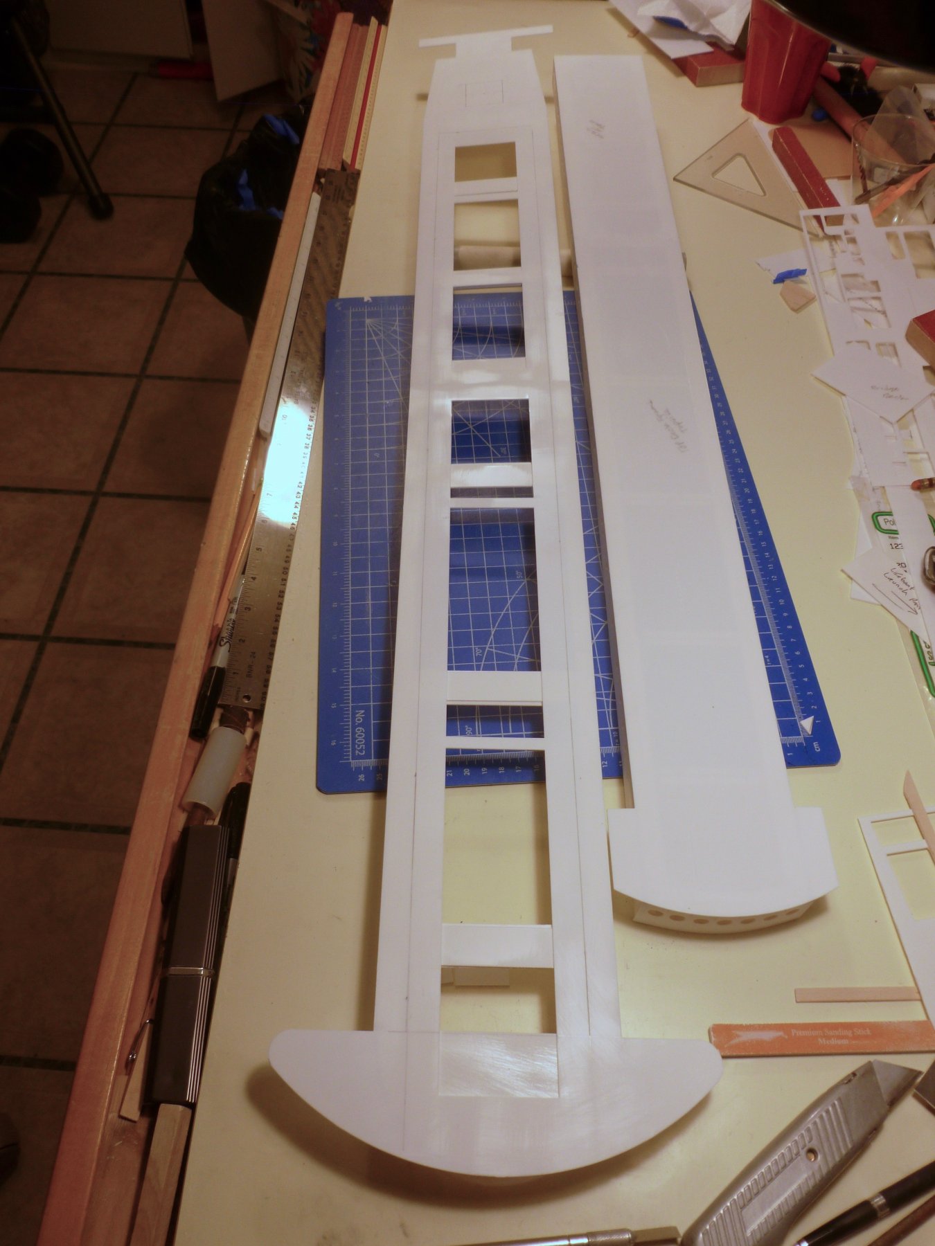
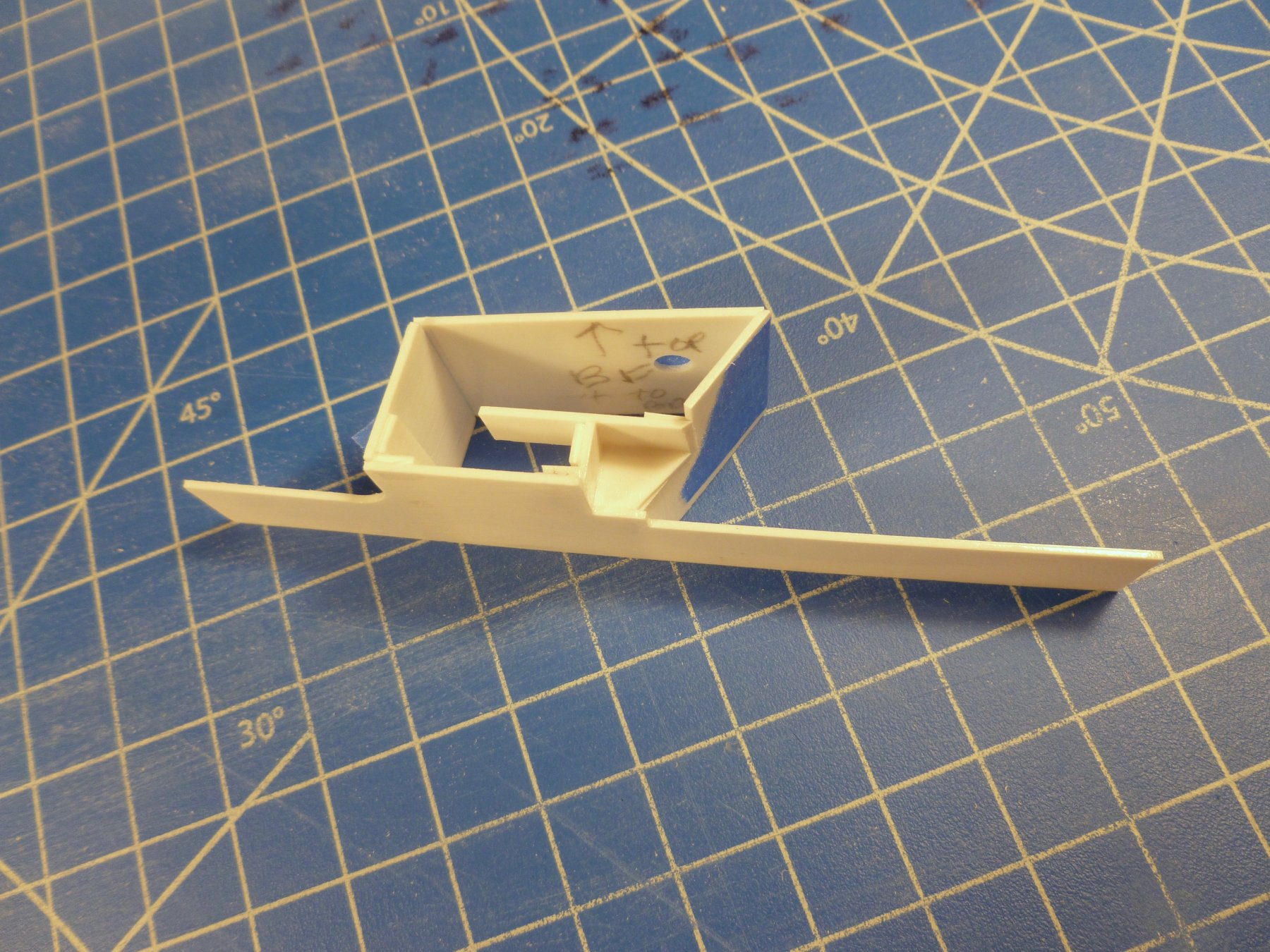
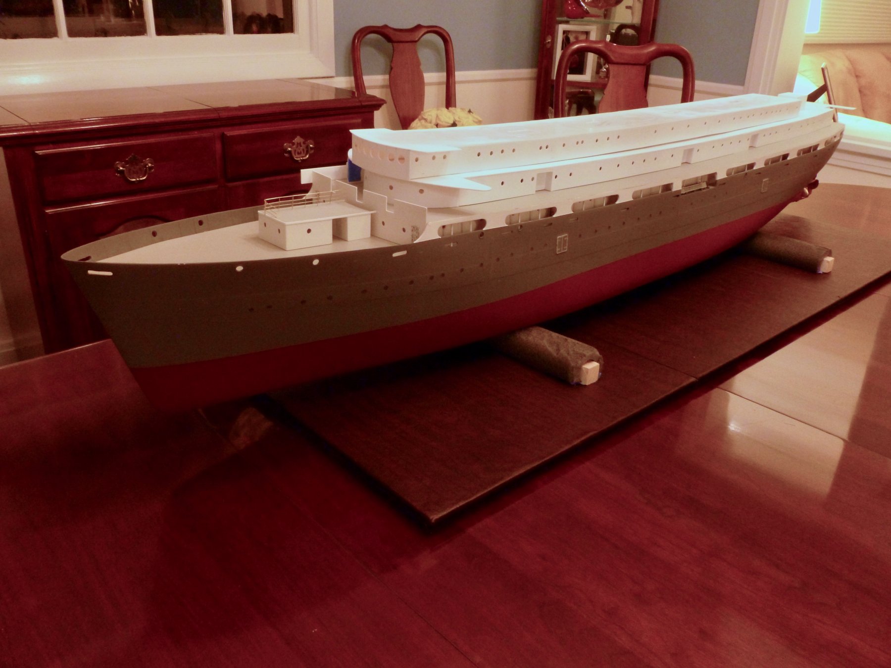
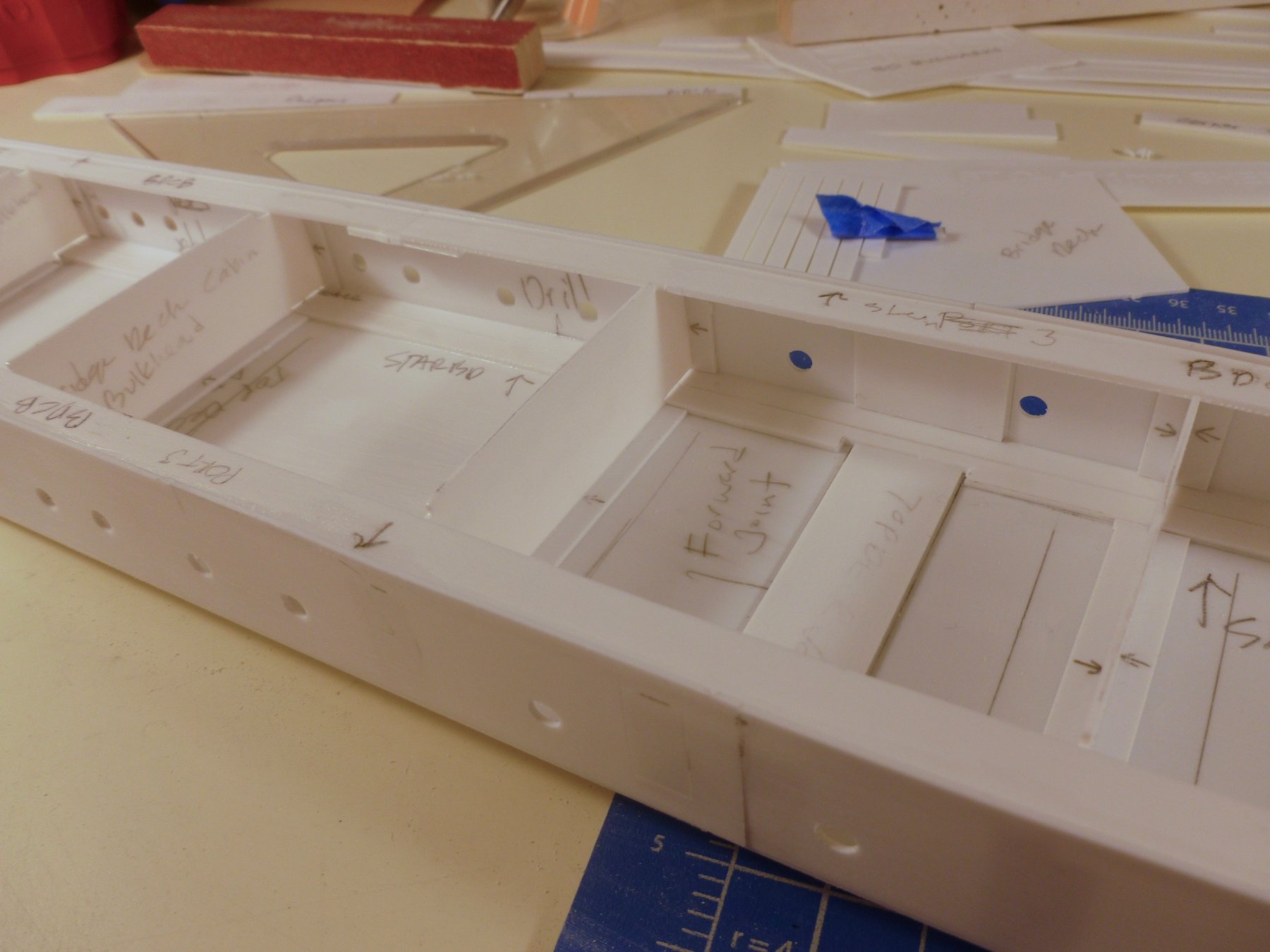
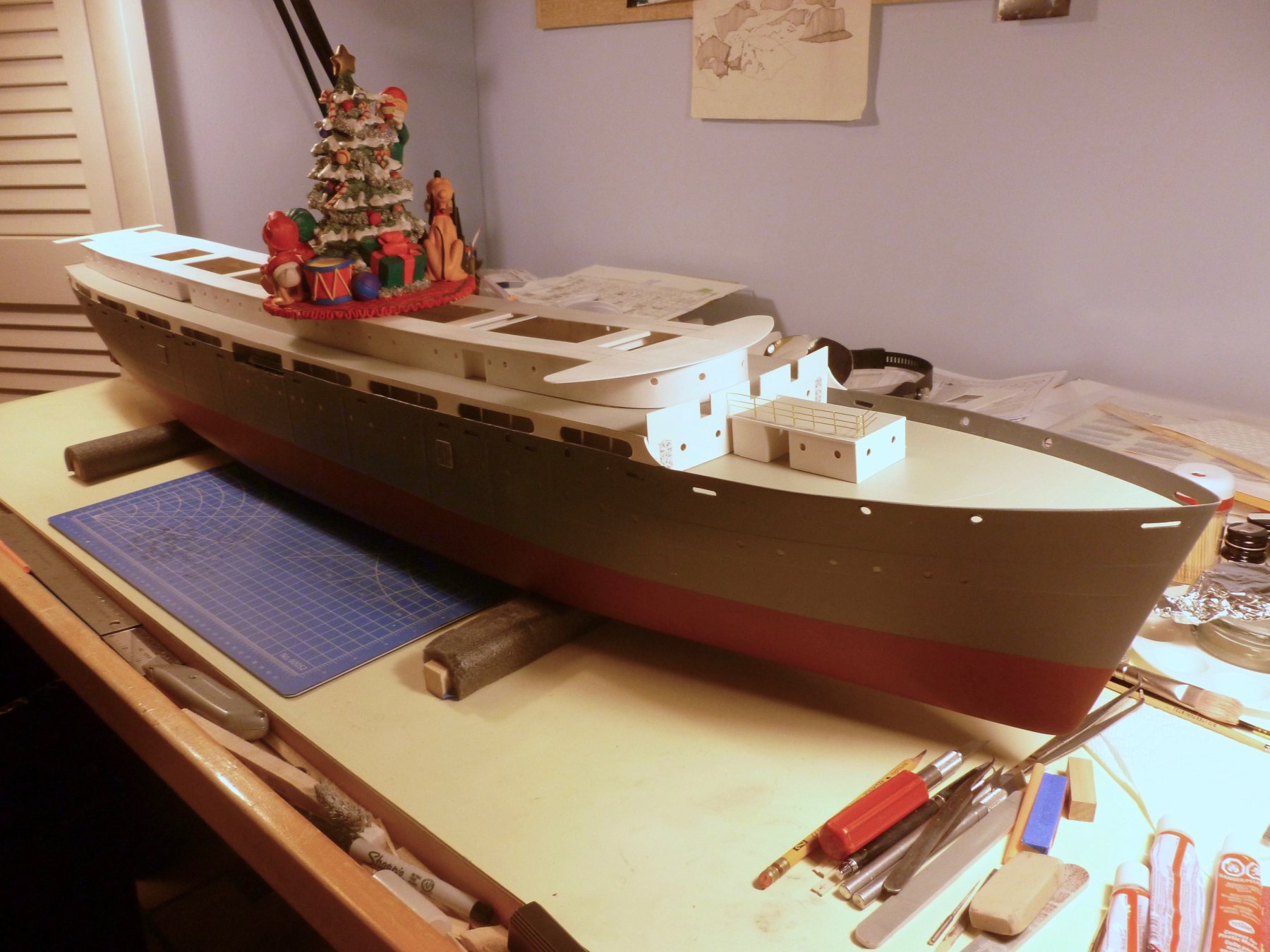
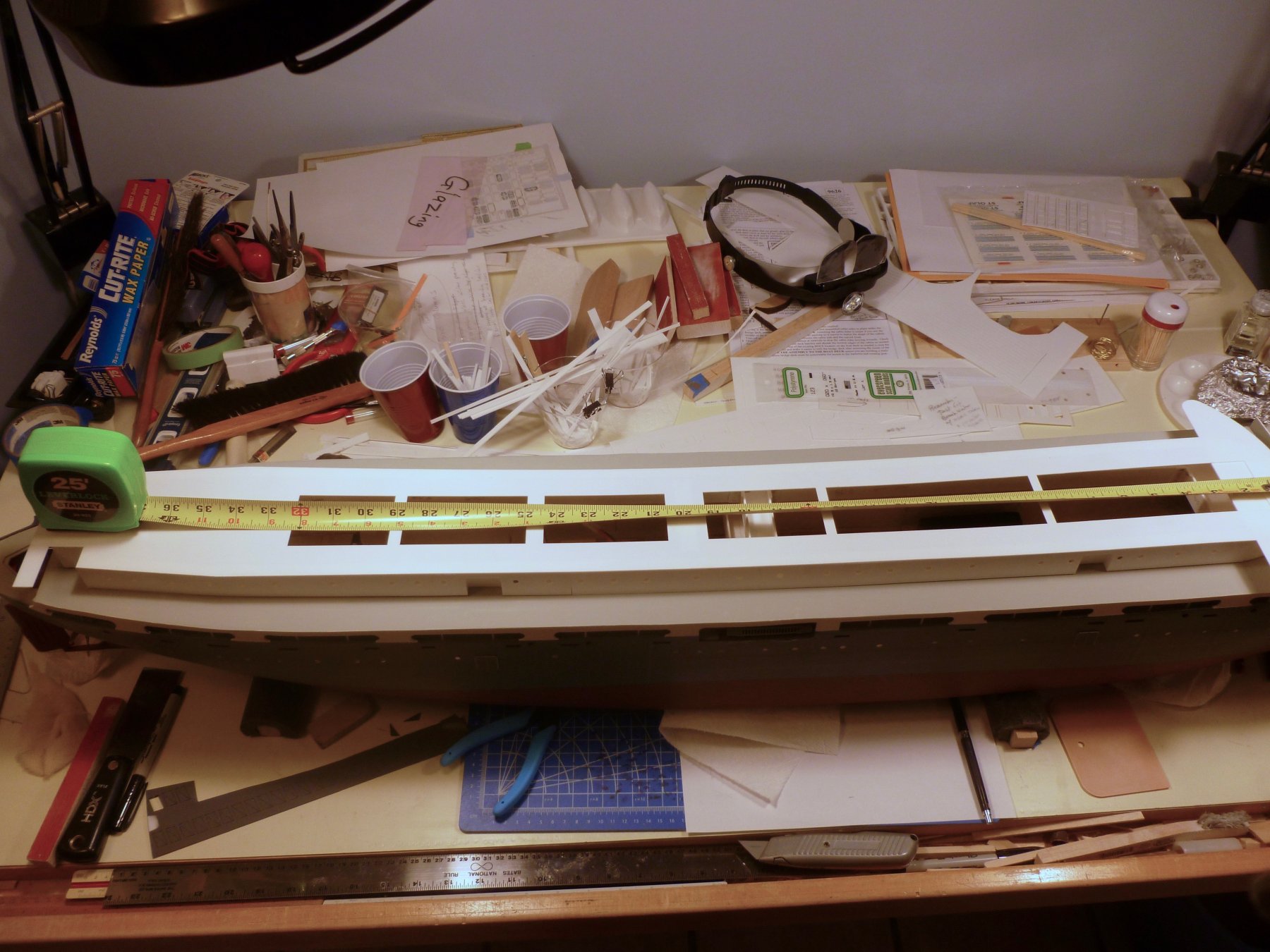
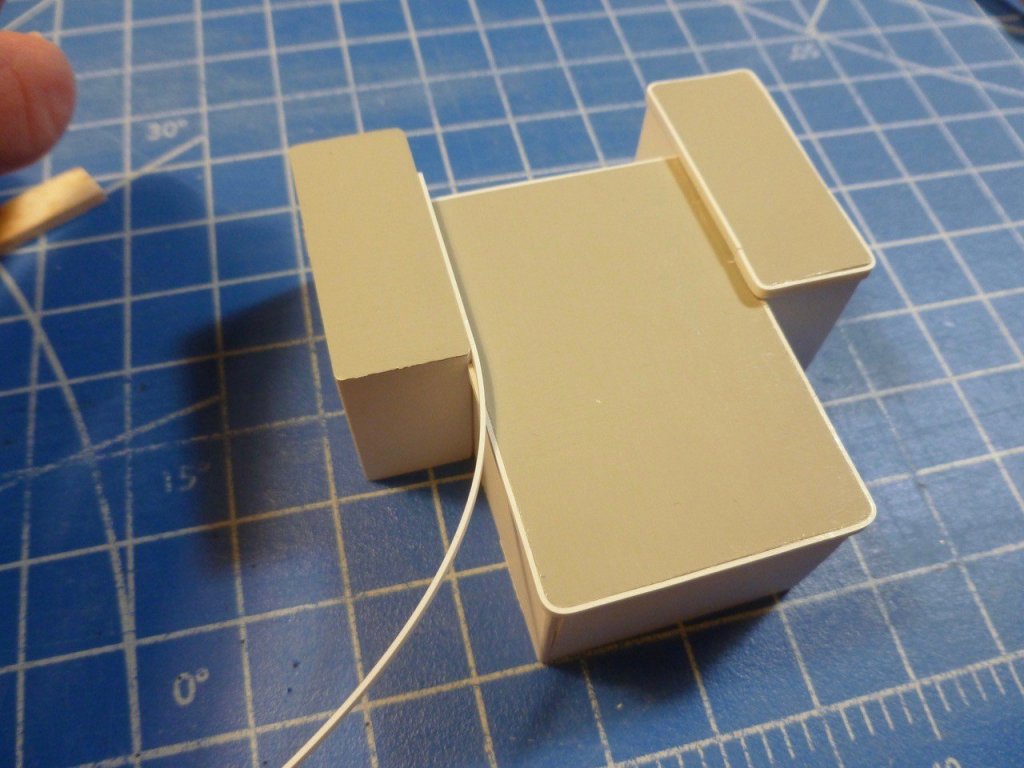
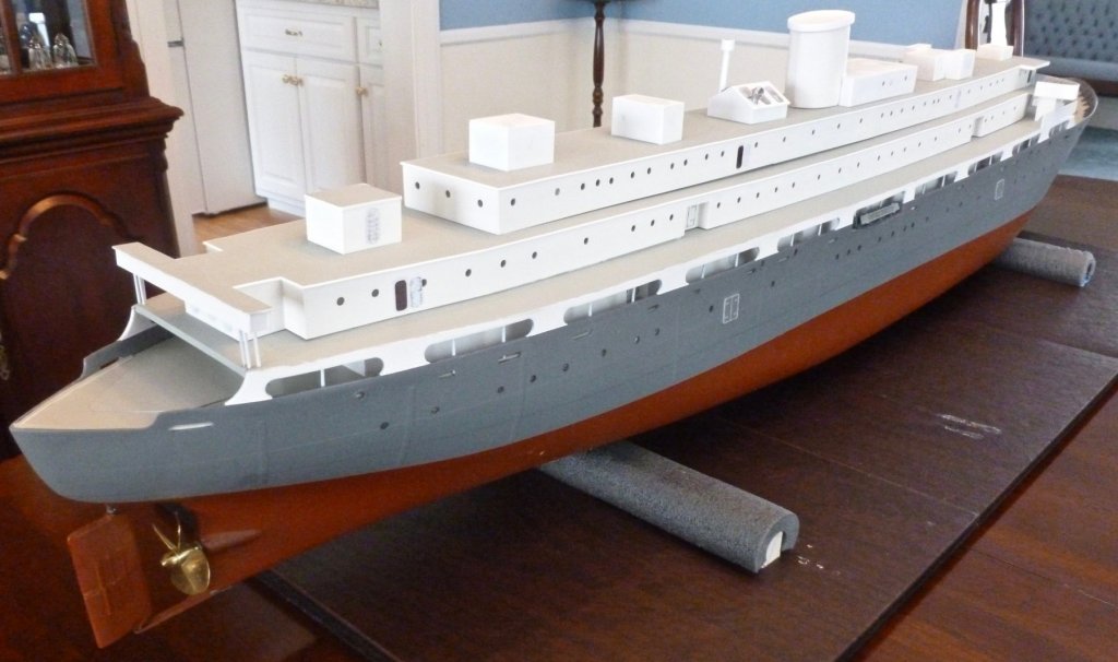
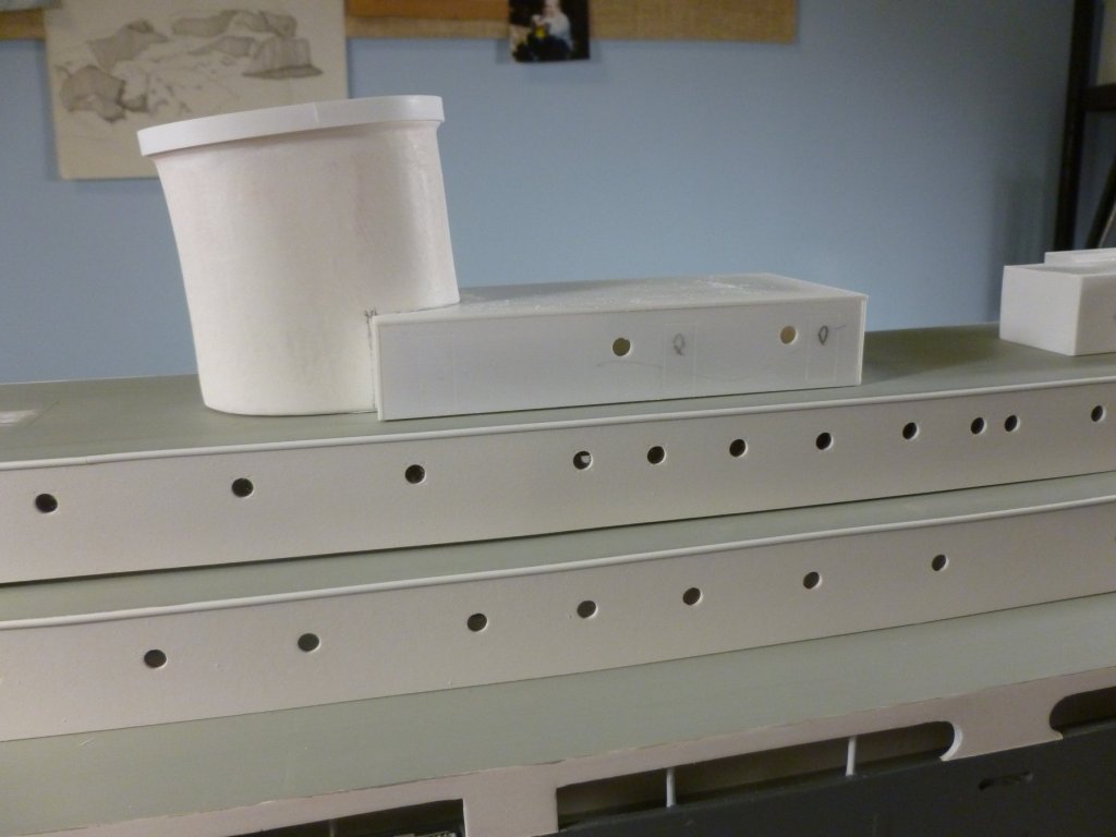
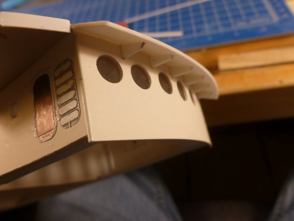
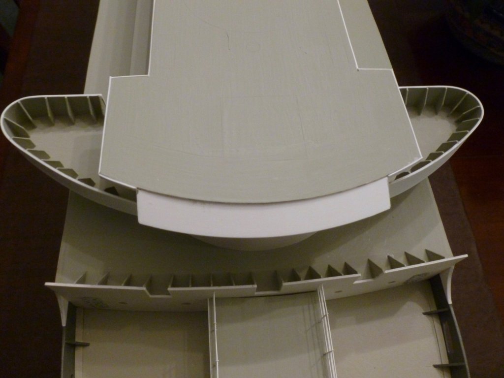
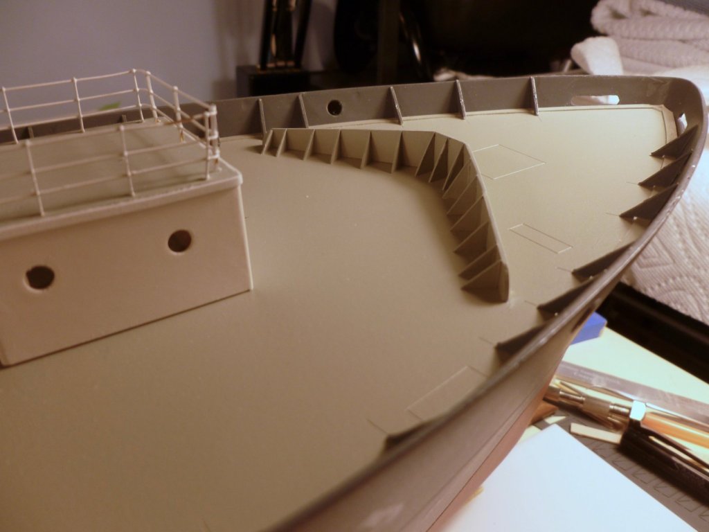
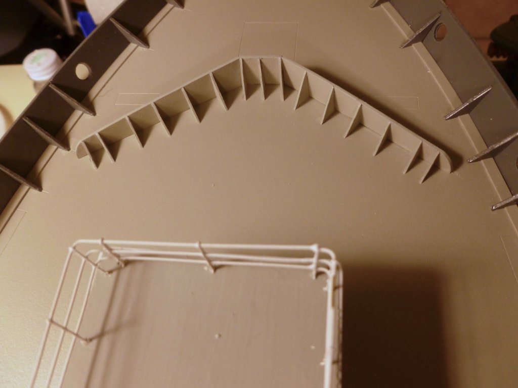
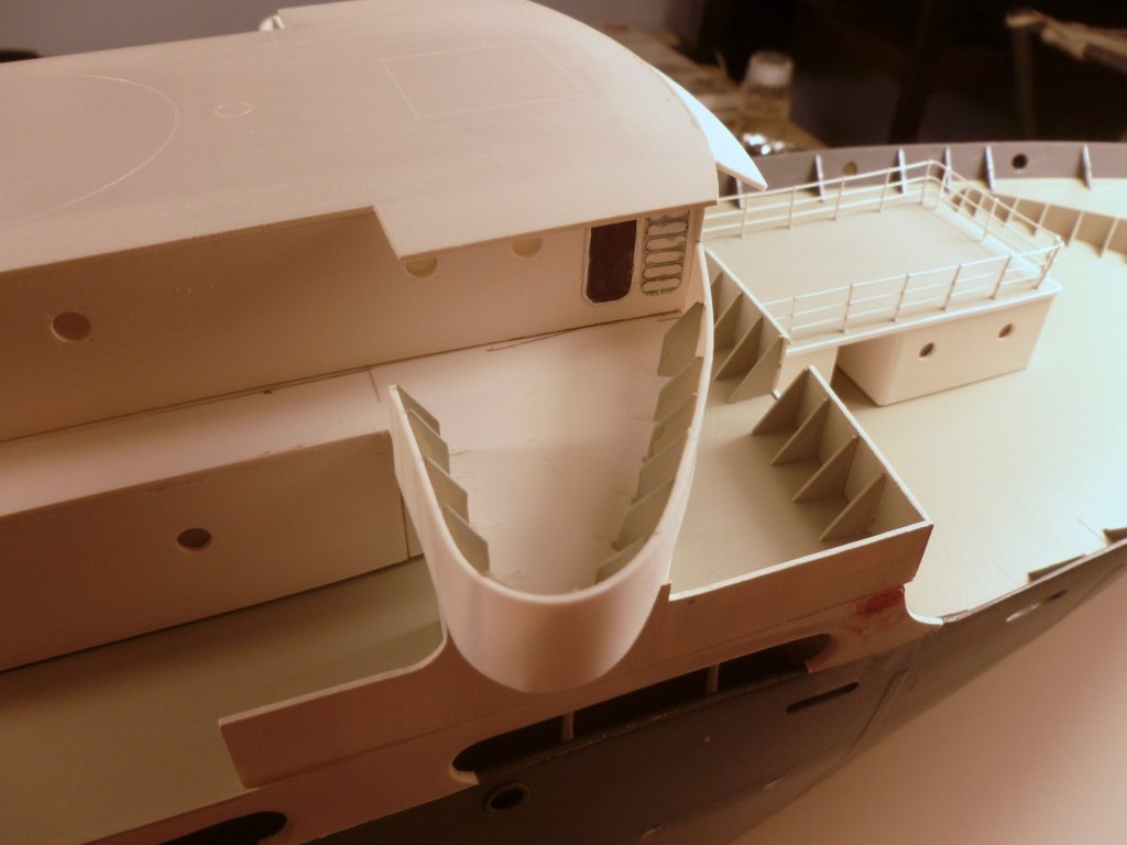
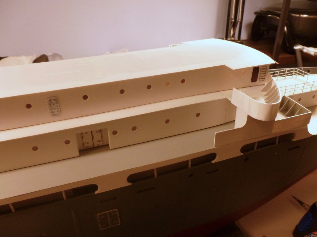
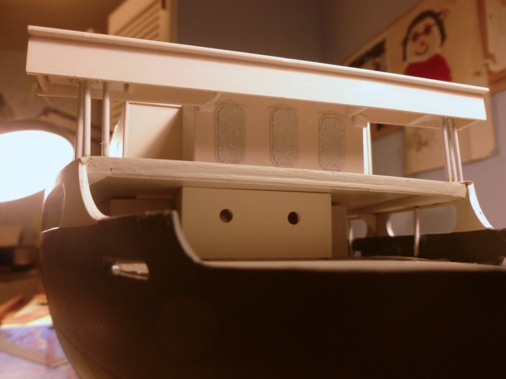
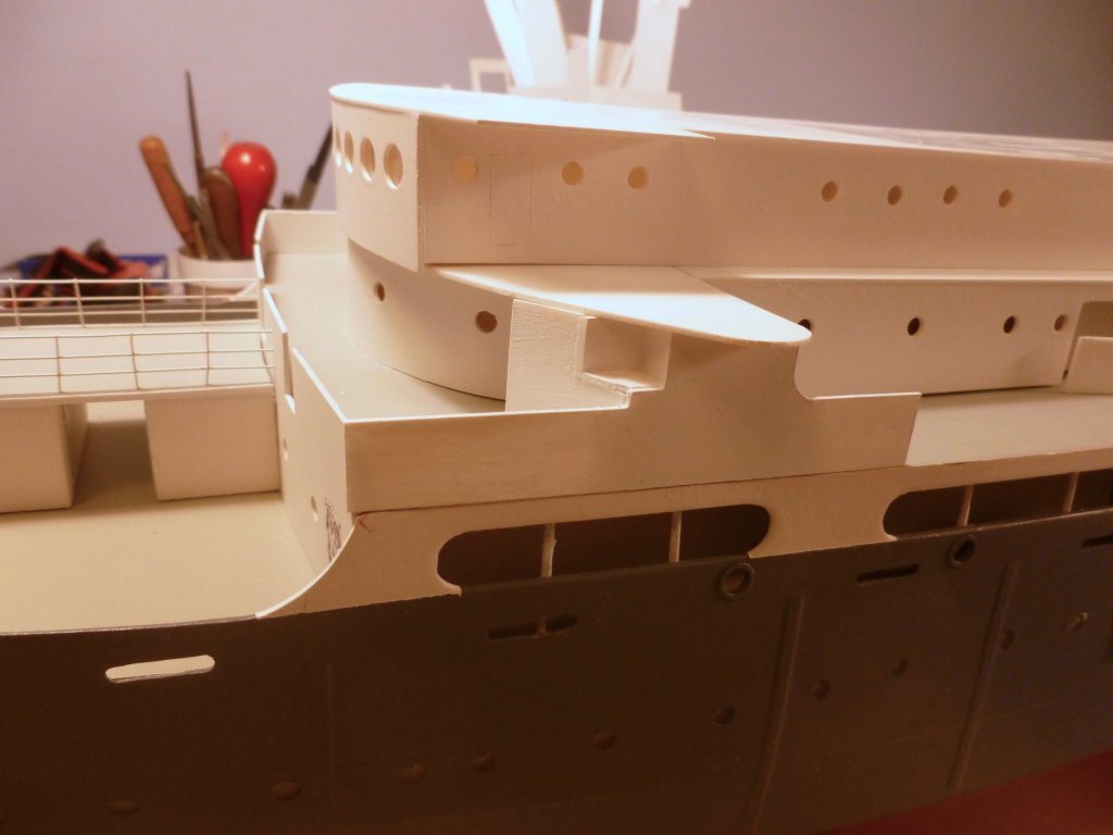
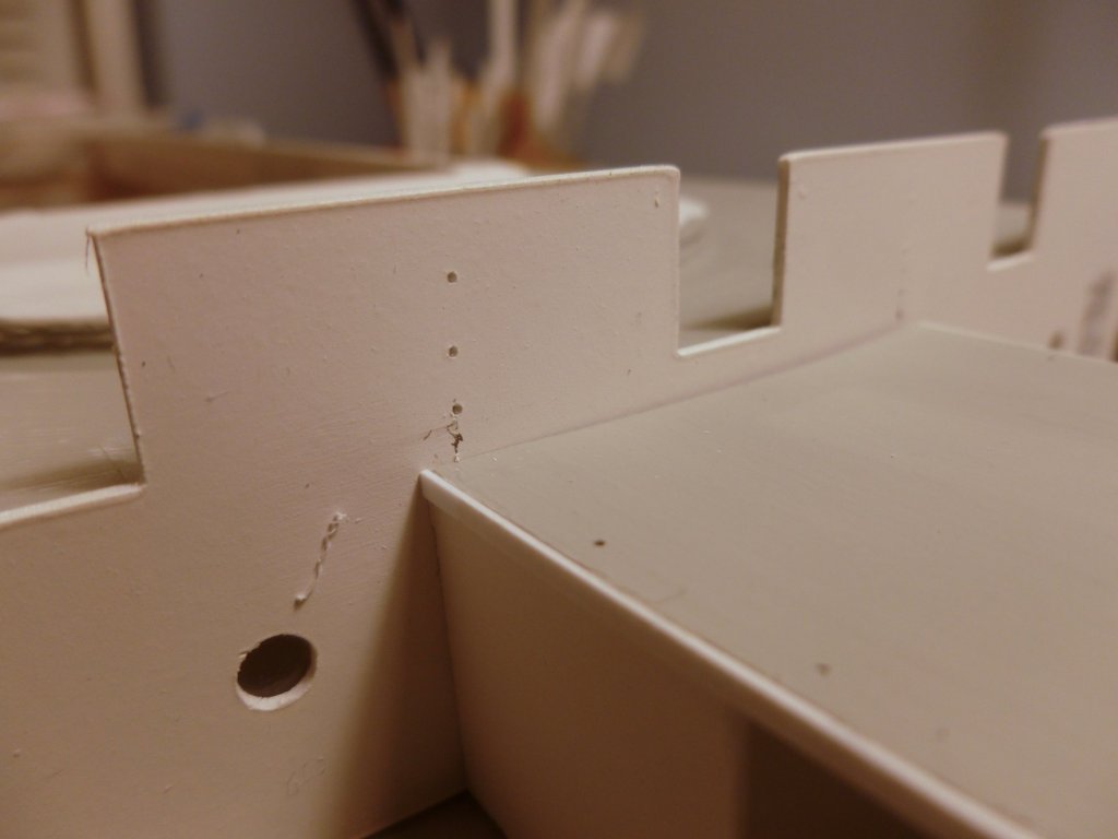
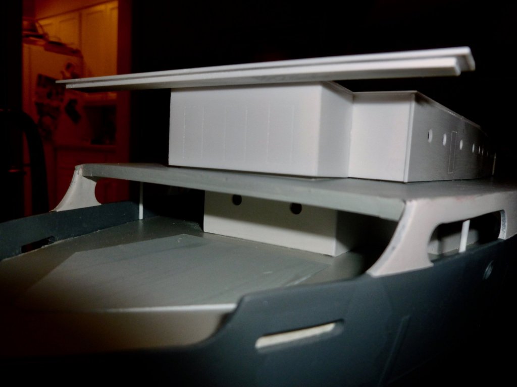
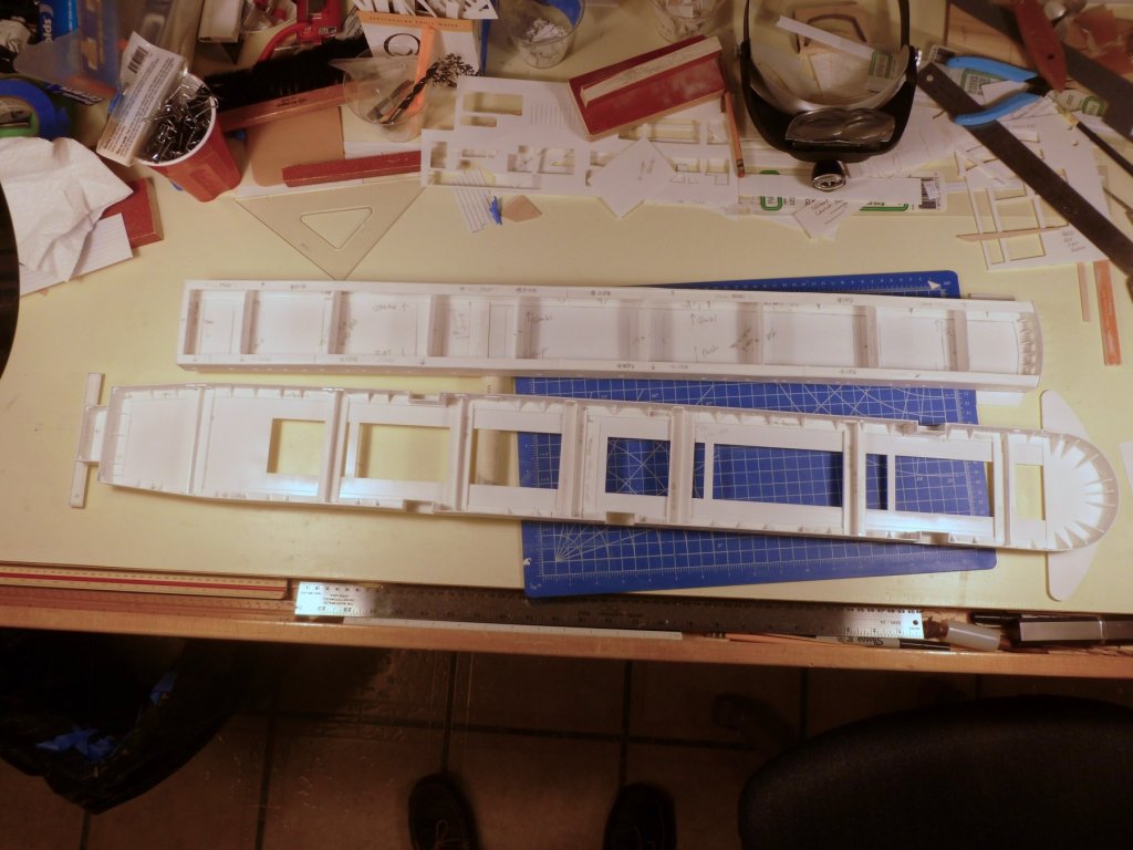
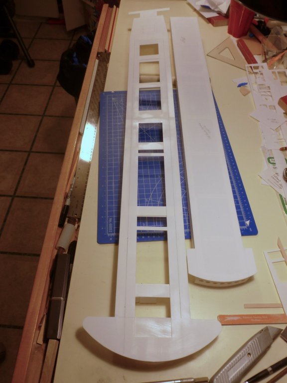
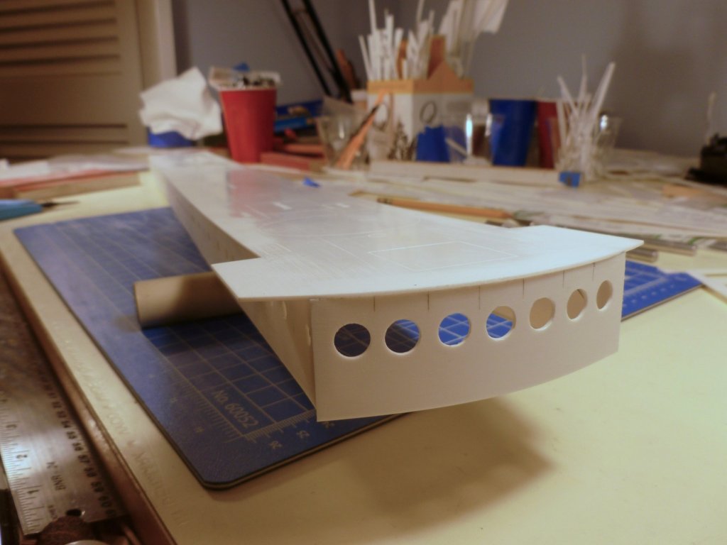
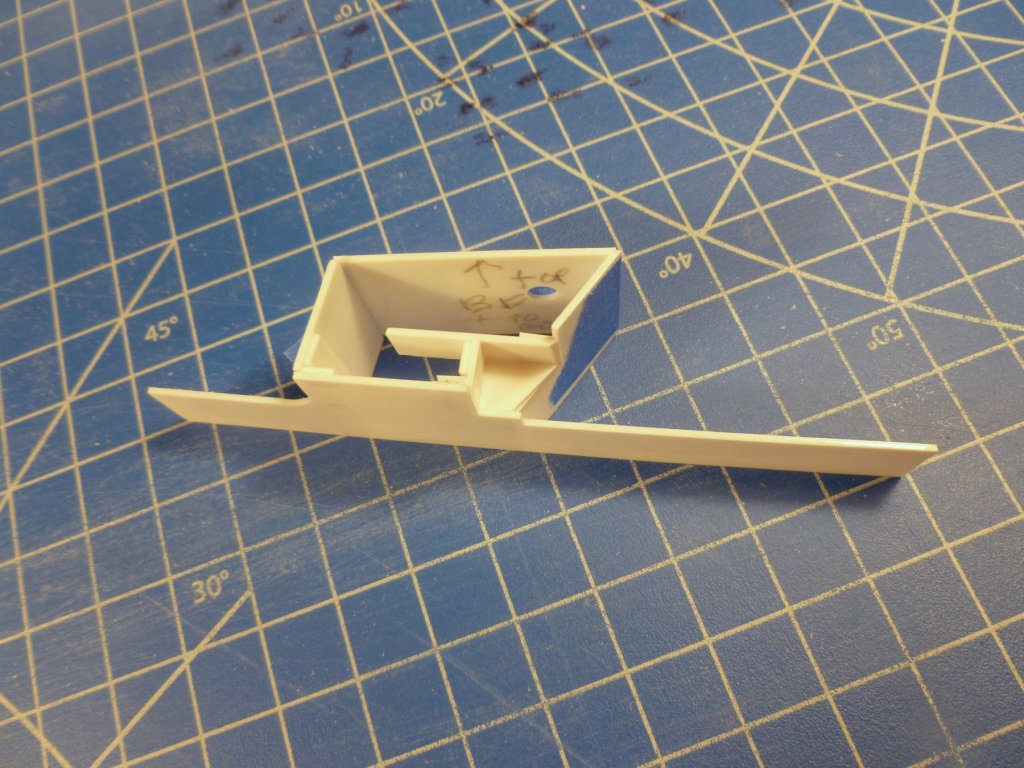
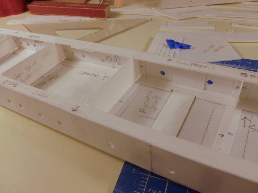
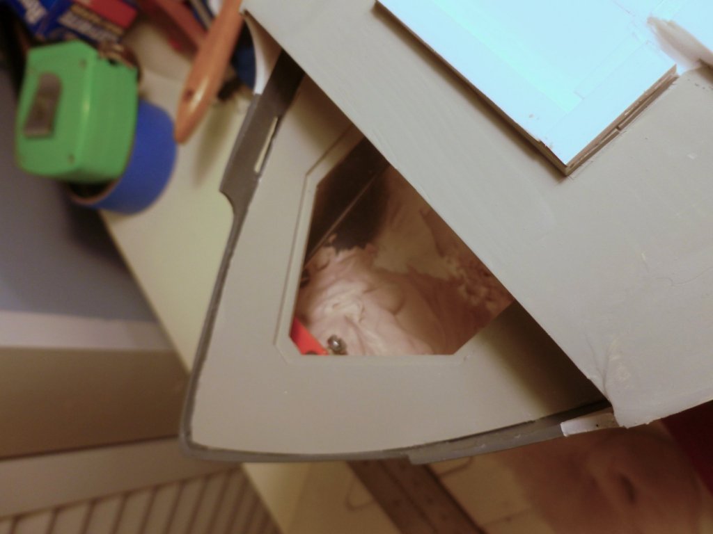
To those who gave likes, thank you and thanks for stopping by. Scott, thank you for your interest and your compliment. I wish you best of luck with your Liberty ship. Lou, you read the manufacturer’s mind. The photos below show all the structure under the top and bridge decks. I’ve also included a closeup of the aft bridge area to show where the column question was. Regarding the flat deck opening over the rudder arm, I will seal that with silicone. Thanks for the suggestion. Steve Sorry for the bad pic but the Vance is hanging out on the dining room table to make room in the shipyard for fabrication of the upper decks. The photo shows the aft bridge which is attached to the first removable (bridge) deck. The build photos show no columns below the bridge but I’m sort of settled on attaching the columns to the boat deck below and landing them with a top plate in a pocket under the bridge. We’ll see how it goes. Another low light pic showing the overview of progress. Pieces are set in place with no glue or paint. Work this period focused on internal structure for the bridge deck, finishing the boat deck cabin walls which are attached to the bridge deck, work on the underside of the top deck and fiddling with the starboard navigation light housing. Oh, and the never ending job of porthole drilling.... Bridge deck and top deck side by side. The assembly is as follows: Boat deck glued to hull. Boat deck cabins installed to underside of bridge deck. Bridge deck cabins installed to underside of top deck. The bridge and top decks will be glued together, then the assembled unit is placed loose on the boat deck - well not really loose since the boat deck cabin wall fits tight to a curb around the boat deck. I’m happy with the bridge portholes. Multiple big holes, small wall, lots of opportunity to mess up. I tested the new brad point drill bit on some scrap and found it had a propensity to gouge the surface with the two perimeter cutting points, so I taped everything except the awl-marked centerpoints and drilled very, very slowly. Worked well although there was a tendency for tape bits to get carried along by the cutting points, especially where there was more than one layer of tape. And the really good news is that the wall didn't split when it was glued to the curve. This high view shows the structure under the bridge and top decks. The top deck (shown above upside down) receives the bridge deck cabin walls after a locating strip is attached to the underside of the top deck. In addition to the strip the structure consists of stiffening triangles at the top of the walls, cross-deck full depth bulkheads and a continuous 10 mm strip along the inside wall base to ensure the wall line is straight. Remember this is all being built upside down. All in all a pretty rigid structure. The underside of the bridge deck gets the triangles and the bulkheads, and the wall base slides over a triple layer of continuous locating strips attached to the boat deck. The starboard navigation light housing with attached room is interesting. A few bits with a very sketchy drawing to show how they are assembled. It’s strange the wall tops don’t line up. The placement is under the forward bridge deck wing and I may need to “supplement” the wall tops to close the gap if it is not concealed by the dodger wall around the wing.

- 446 replies
-
- 7
-
-
- zebulon b vance
- deans marine
- (and 3 more)
-
To my fellow builders, I wish you and your families the Merriest Holiday and the Happiest New Year. Steve

- 446 replies
-
- 9
-
-
- zebulon b vance
- deans marine
- (and 3 more)
-
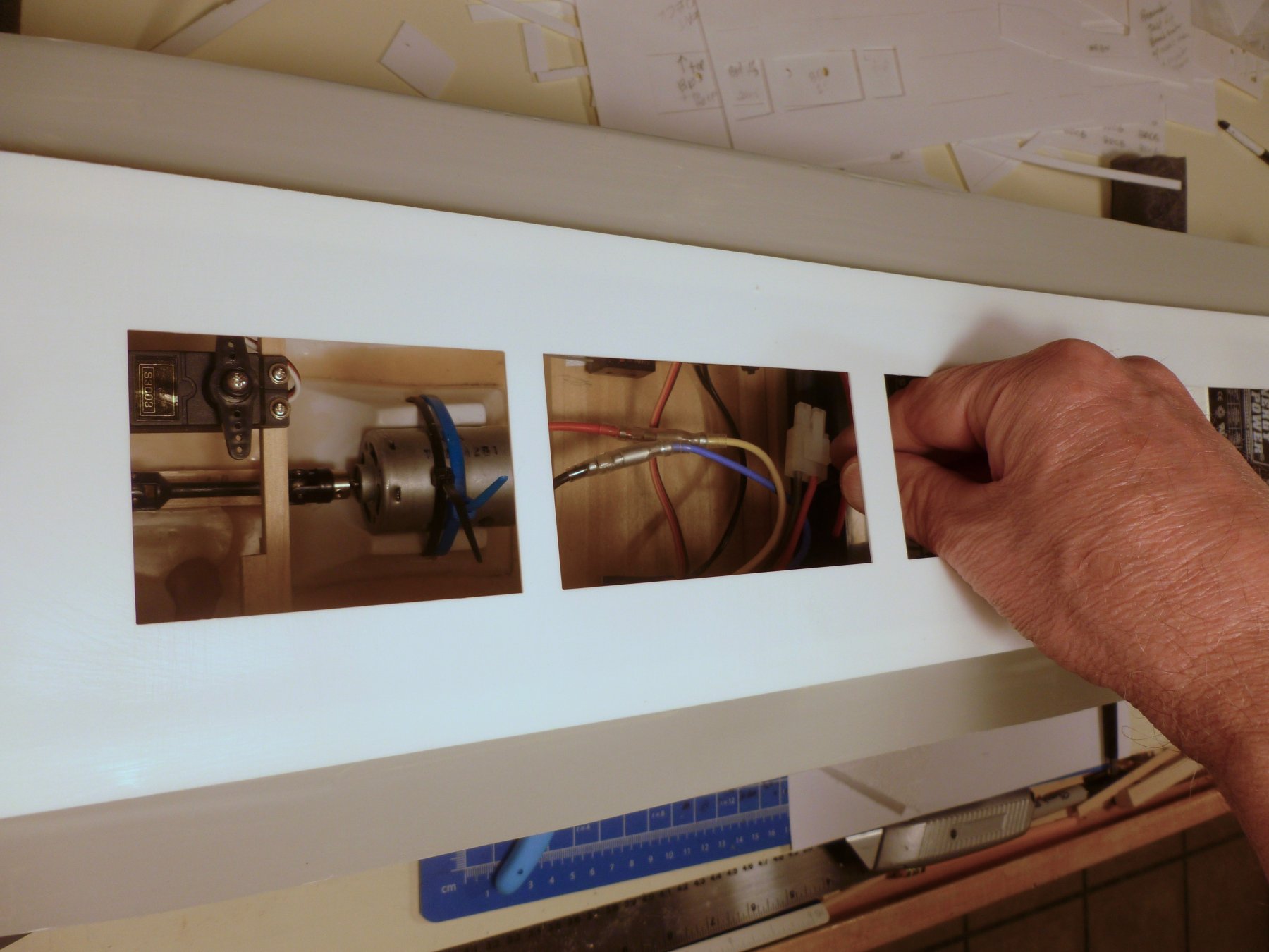
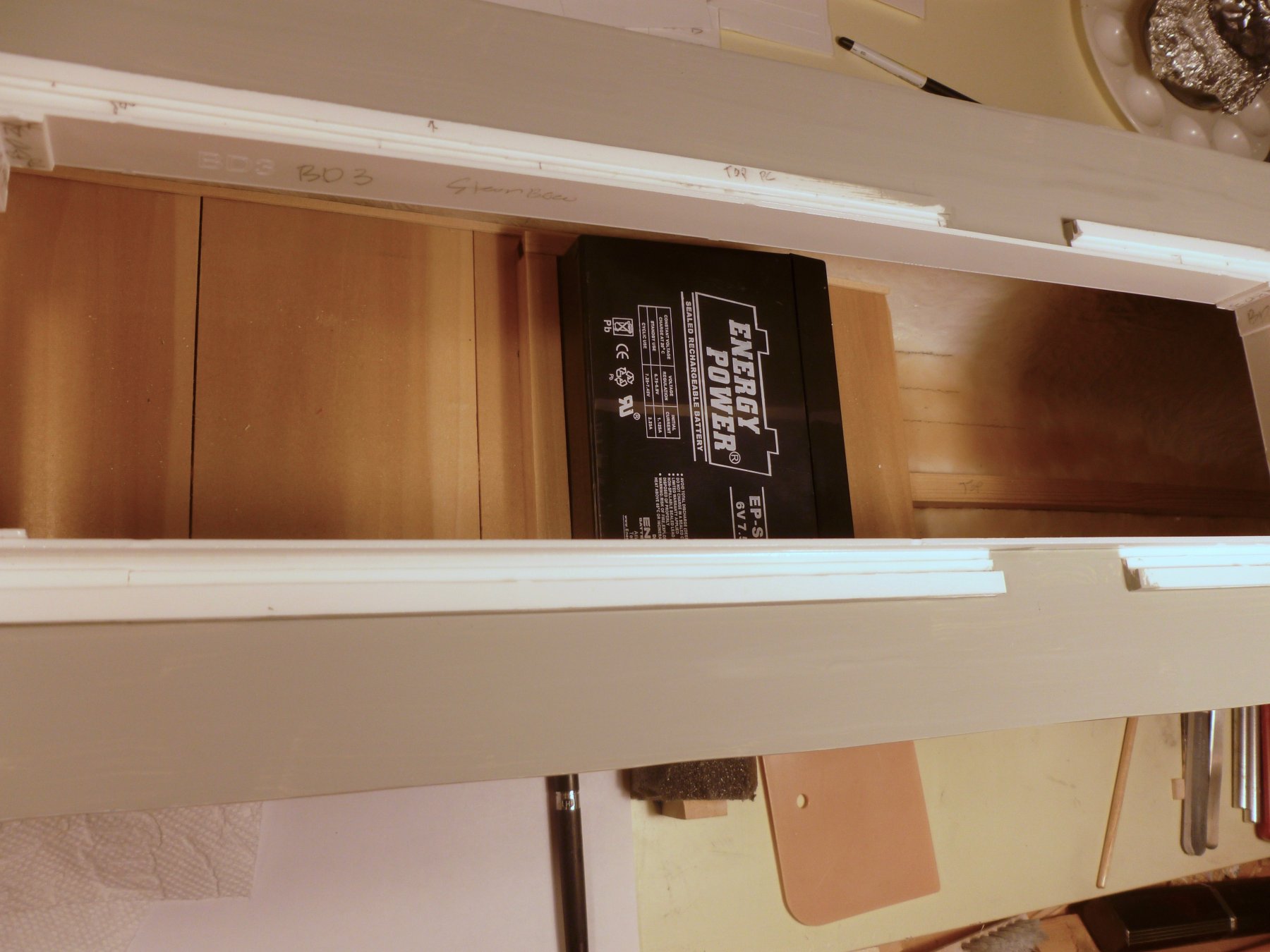
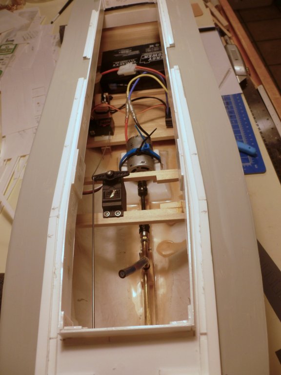
To those who gave likes, thank you and thanks for stopping by. Steve Lou, I was sure I had checked it, but in a panic after reading your access comment I hustled to the boatyard to confirm battery and other access. The aft access panel (I don’t know as I would call it a hatch since it has no coaming) in the main deck allows fiddling with the rudder arm. Take comfort knowing the panel will be painted gray to match the deck. The midship hatch in the boat deck allows good access to the motor, on-off switch, electronic bits and power battery. The forward hatch in the boat deck allows ample access for the spare battery used for ballast. BUT… Once the bridge deck is in place all bets are off. Bear in mind that the bridge deck also supports the progressively narrower bridge cabins, and a still narrower top deck, all of which are glued together, wedding cake style. If I cut the bridge deck I’d also have to cut everything above it which would give a much larger slice of cake than I could probably swallow One thought is whether the forward bridge wings and aft bridge could be stiffened enough to act as handles, but I’m guessing there would be too much load. Maybe I’m overthinking this. Bridge, not balcony. Duh, I guess that’s why they call it the bridge deck. My architectural background tried to trump my naval knowledge, but Carl, you are keeping me on the path to righteousness. I like your idea of using plastic. In scale the columns should be about a 1/16” in diameter (6 inch pipe) and the challenge would be how to align six less-than-needle sized posts with six tubes while maneuvering the bridge deck on and off. I’m thinking maybe I should drill and pin the columns (three at each end) to the deck, and to a top plate to hold them in alignment, and provide a fascia around the underside of the bridge to receive and hide the top plates. Or maybe a single long top plate attached to all the columns, that the bridge would rest on.


- 446 replies
-
- 6
-
-
- zebulon b vance
- deans marine
- (and 3 more)