HOLIDAY DONATION DRIVE - SUPPORT MSW - DO YOUR PART TO KEEP THIS GREAT FORUM GOING! (Only 13 donations so far - C'mon guys!)
×


ESF
-
Posts
381 -
Joined
-
Last visited
Content Type
Profiles
Forums
Gallery
Events
Everything posted by ESF
-
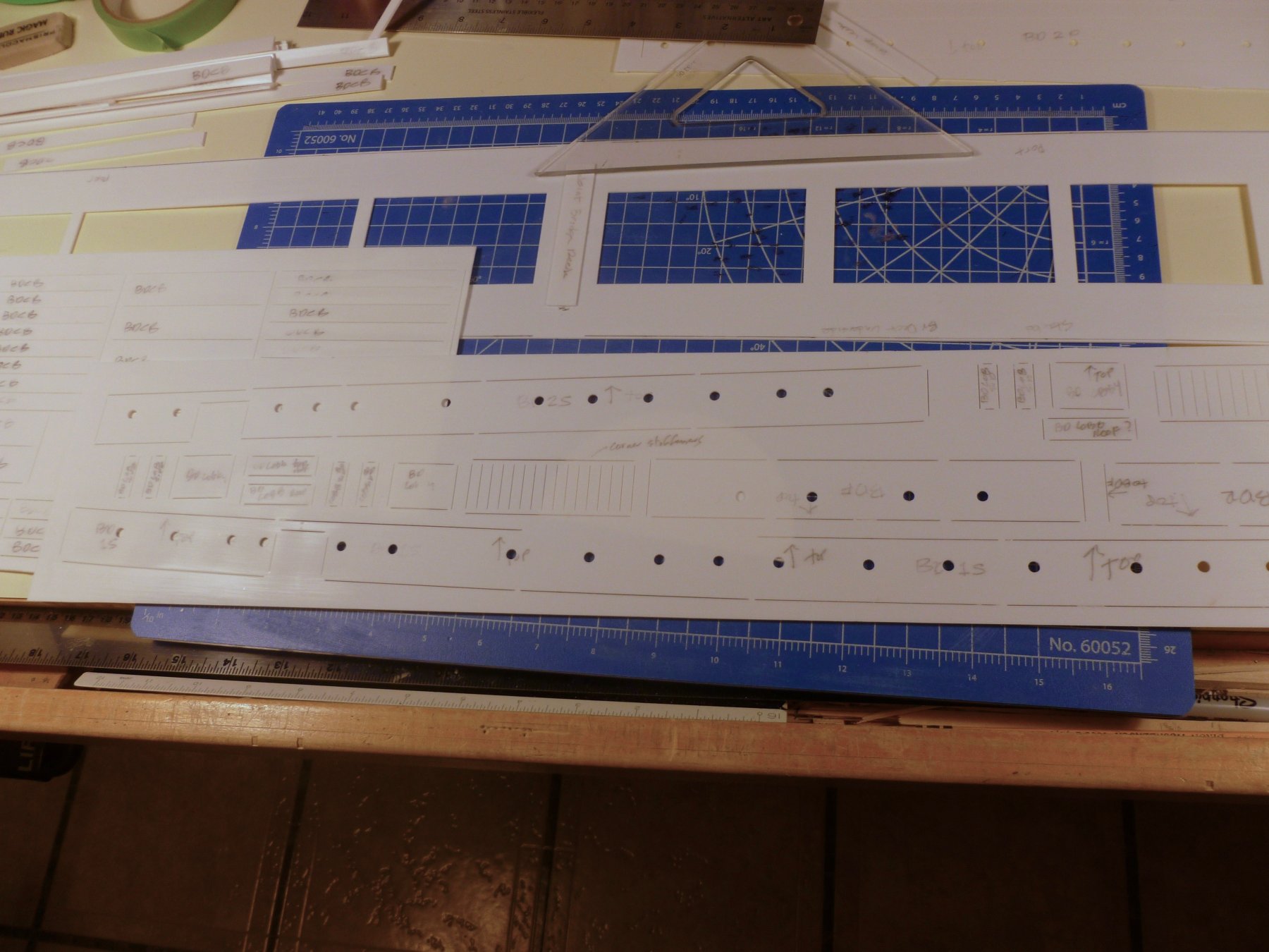
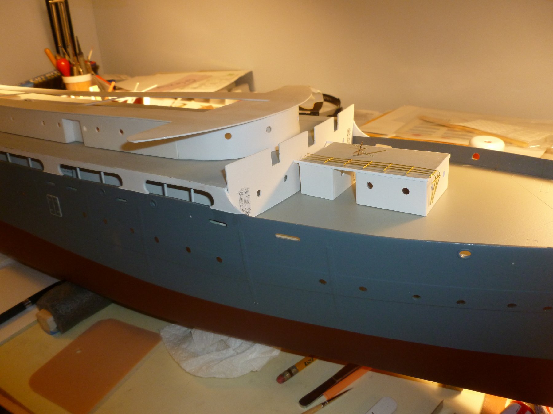
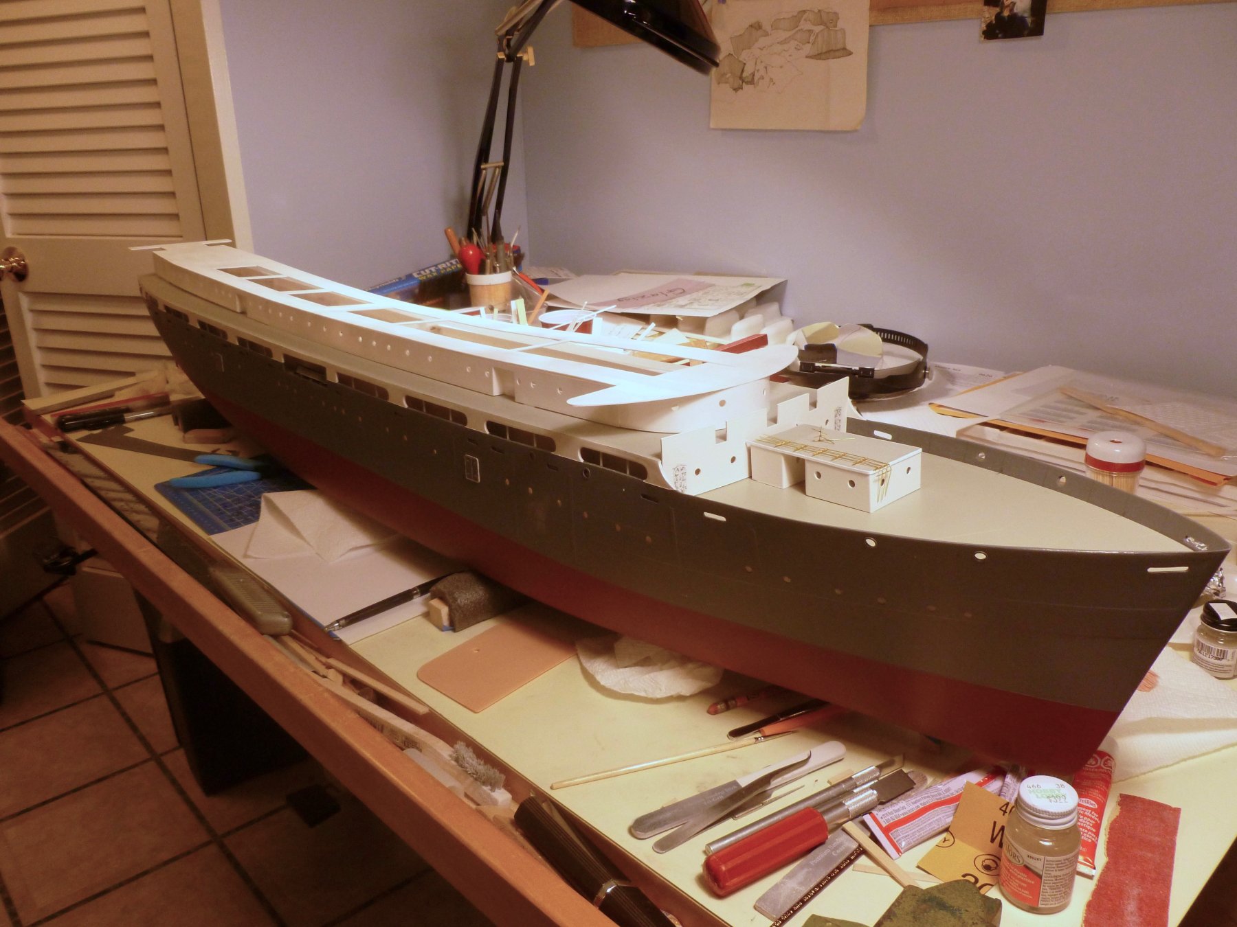
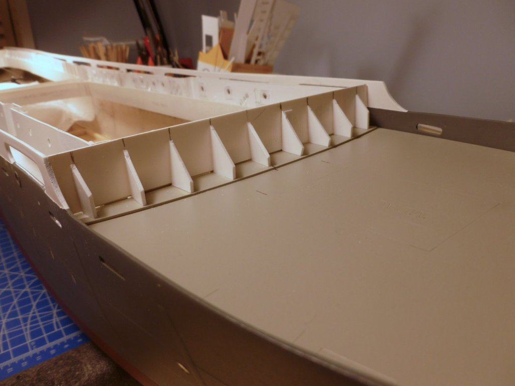
 To those who gave likes, thank you and thanks for stopping by. Carl, thanks once more for sharing your wealth of knowledge. I have received many good ideas from all the members and look forward to testing my skills. Steve Work started on the boat deck cabins after drilling more portholes and extracting parts from the carrier sheet. All pieces must be marked on the back. The boat deck cabins are installed upside down on the underside of the bridge deck. As noted before they will not be glued to the boat deck since everything above the boat deck must be removable for access to the RC innards. During thinking time, while pedaling the exercise bike, it occurred to me that there will be a big challenge to remove the upper decks after they are detailed with railings, ladders and other bits. Where do you grab it? How do you squeeze it up off the boat deck when the boat deck is surrounded with 16 life boats on davits? The cabin tops are anchored to continuous strips glued to the bridge deck and the walls are stiffened with triangles. After all walls are placed a series of cross braces will be installed too. An overview of progress. The boat deck is primed and has one finish coat. Needs another. A closer view of the forward area with temporary placements. A view of the stern. The aft balcony(?) area of the bridge deck is shown with no visible means of support at each end, but ship photos show there were three pipe columns at each end, extending from the boat deck to the underside of the balcony. This is what got me thinking about deck removal/replacement and all the bits and pieces. If I install the columns they must be attached to either the boat deck or the underside of the bridge deck, but how do you keep them stable while the decks are separated? That probably explains why the columns were ignored during model development. Decisions decisions.

- 446 replies
-
- 8
-

-
- zebulon b vance
- deans marine
- (and 3 more)
-
Thanks Carl. I would have thought that an elastic thread would topple the stanchions, which just goes to show how little I know.
-
Beautiful job Carl. Happy Holidays to you and yours. Will you be gluing or soldering the stanchion rigging? In either case what's your choice of weapon? Thanks Steve
-
Carl, you're a master at this stuff. Do you think a dilute whitewash would tone down the doors? Bear in mind I am not airbrush enabled. Thanks Steve
- 446 replies
-
- 2
-
-
- zebulon b vance
- deans marine
- (and 3 more)
-
Bill, a wonderful job expanding on a very nice ship. The extra detailing is terrific. Steve
-
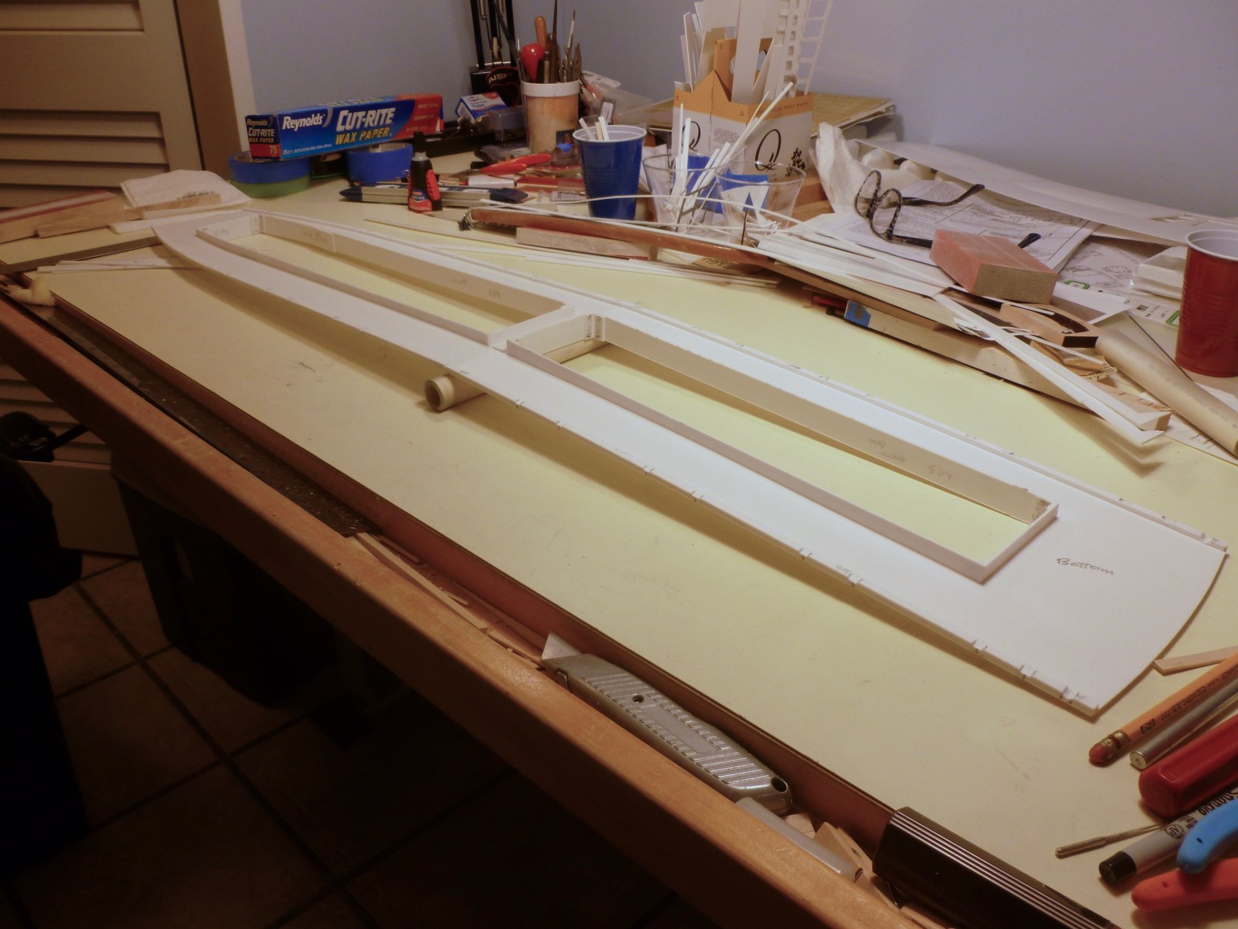
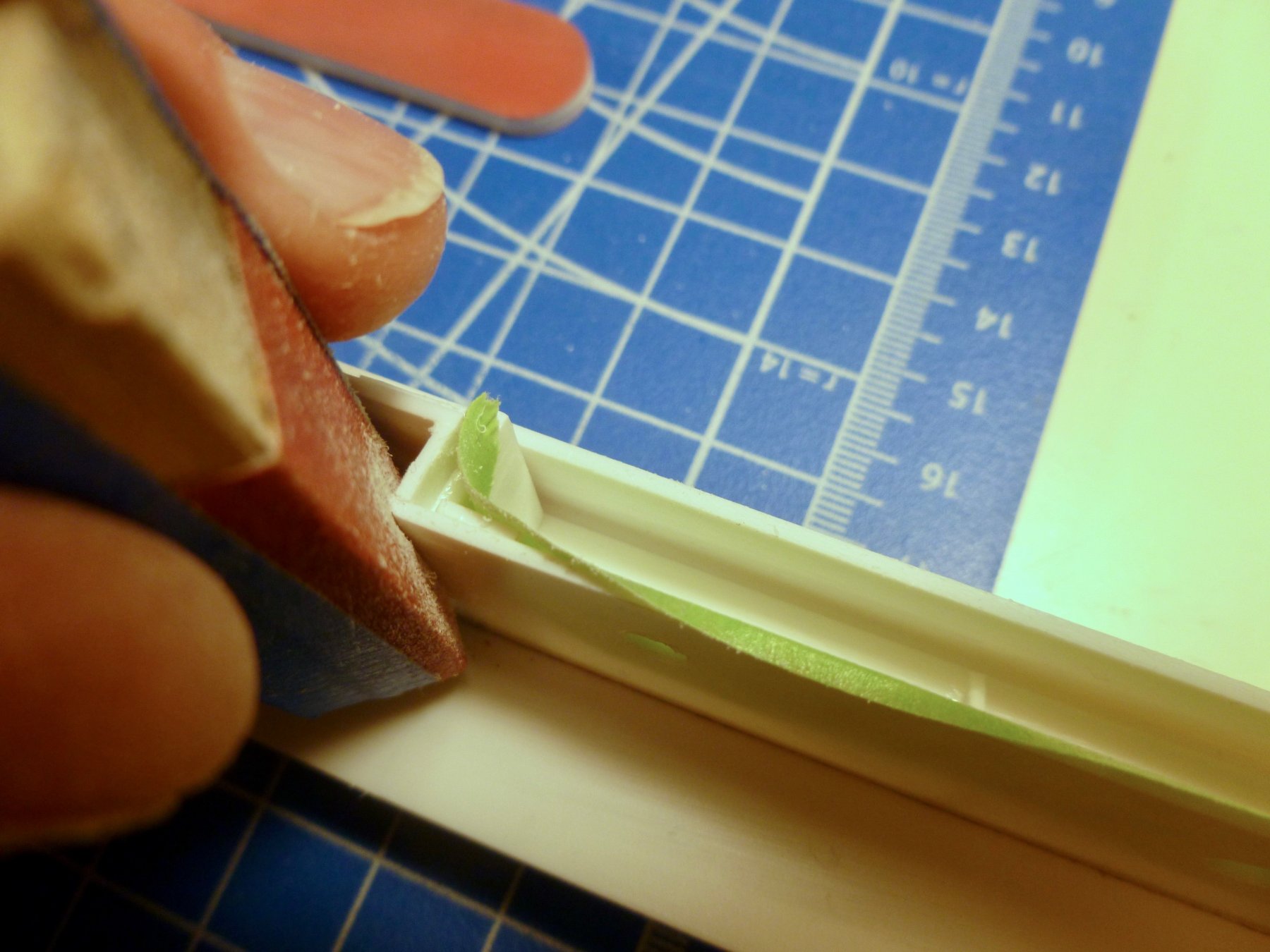
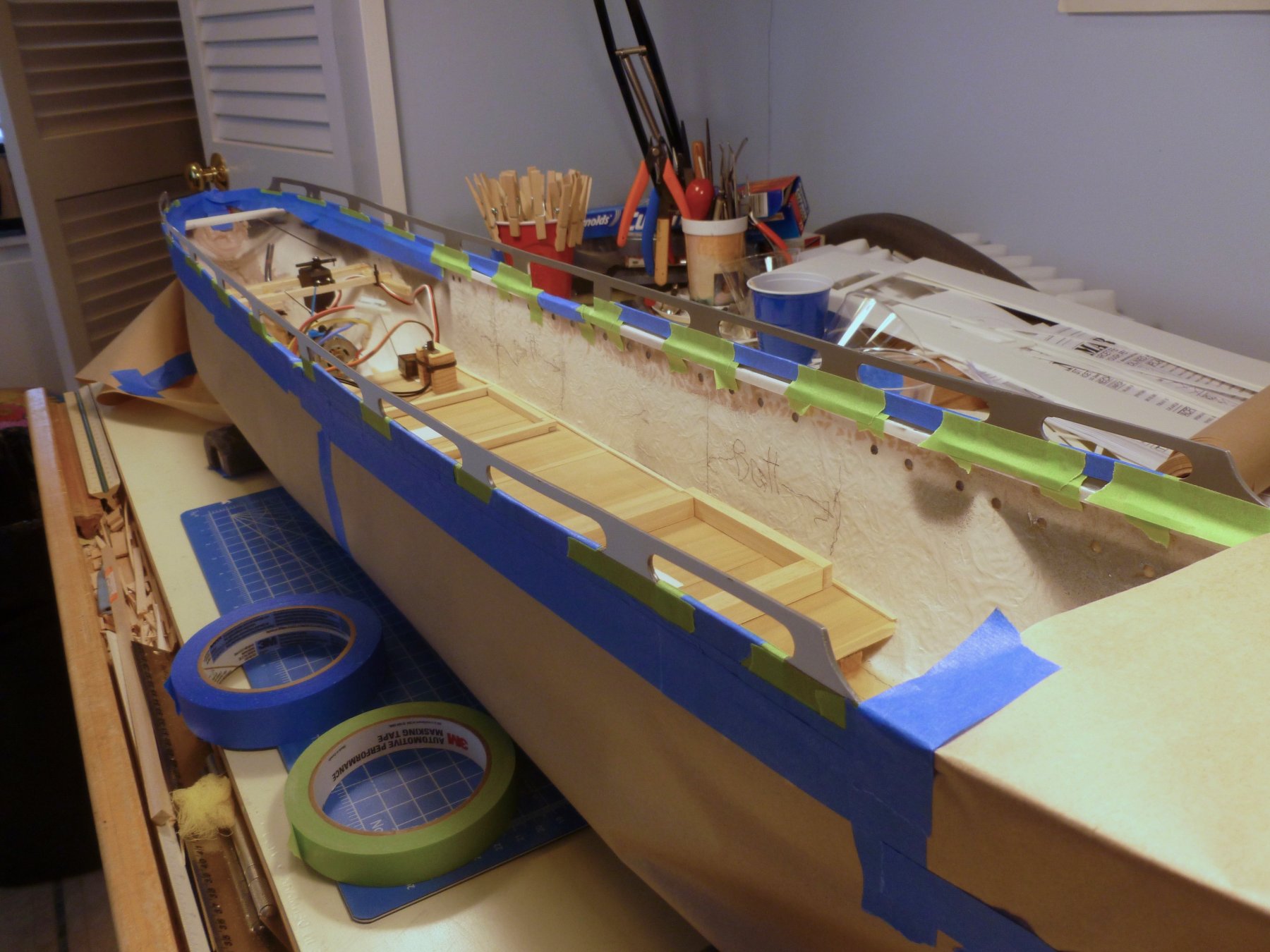
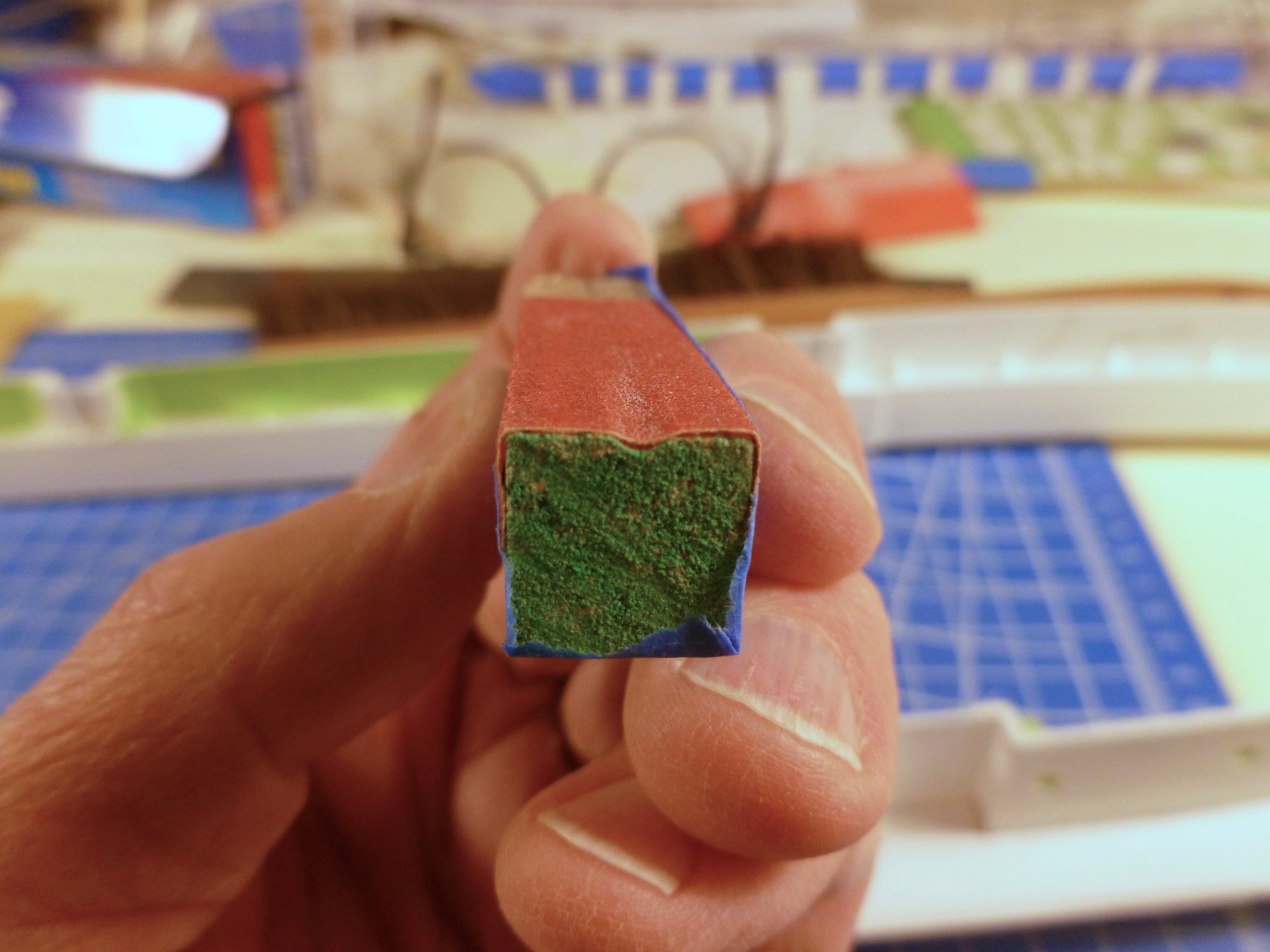
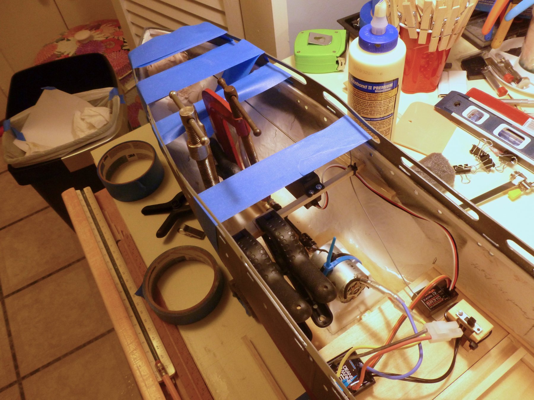
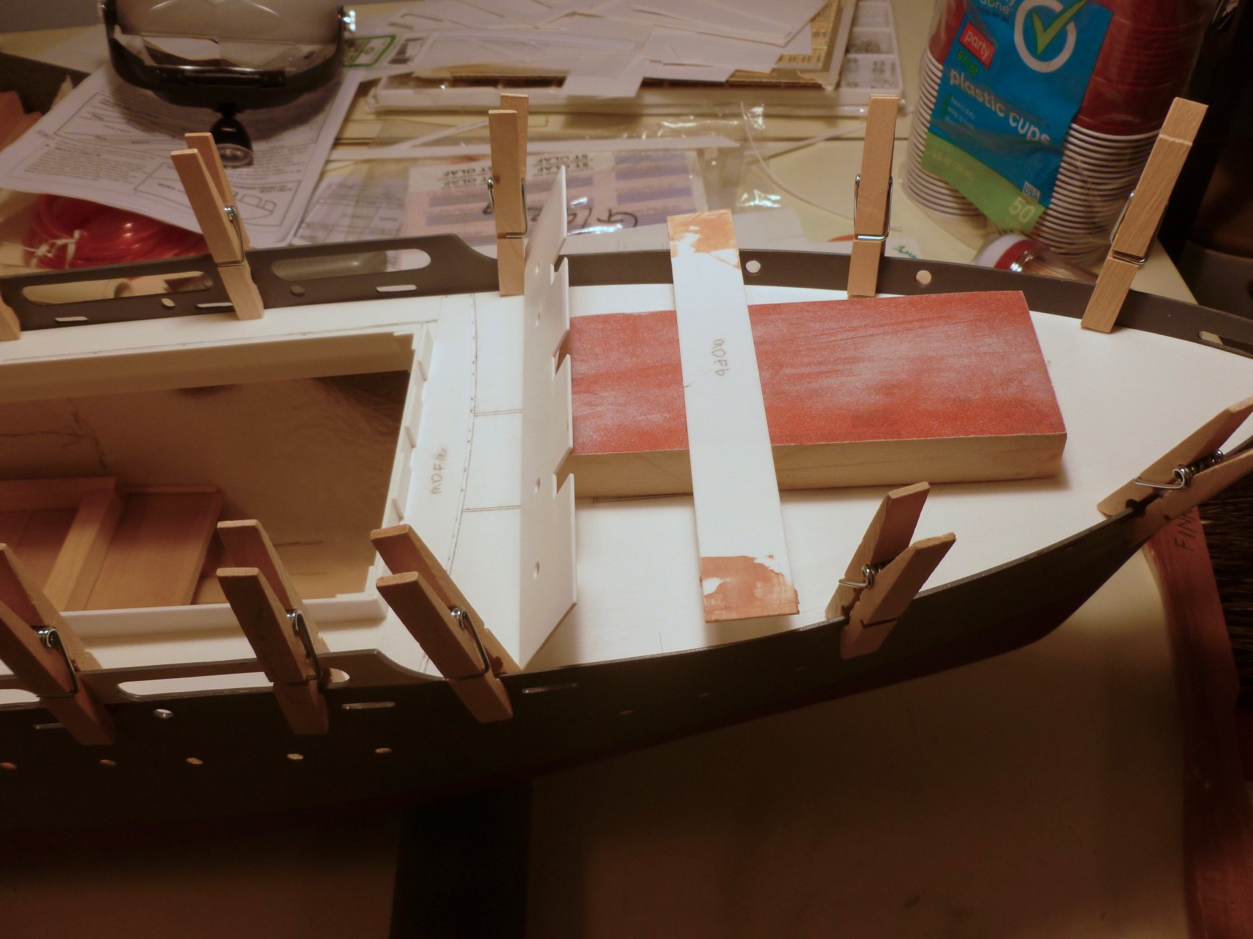
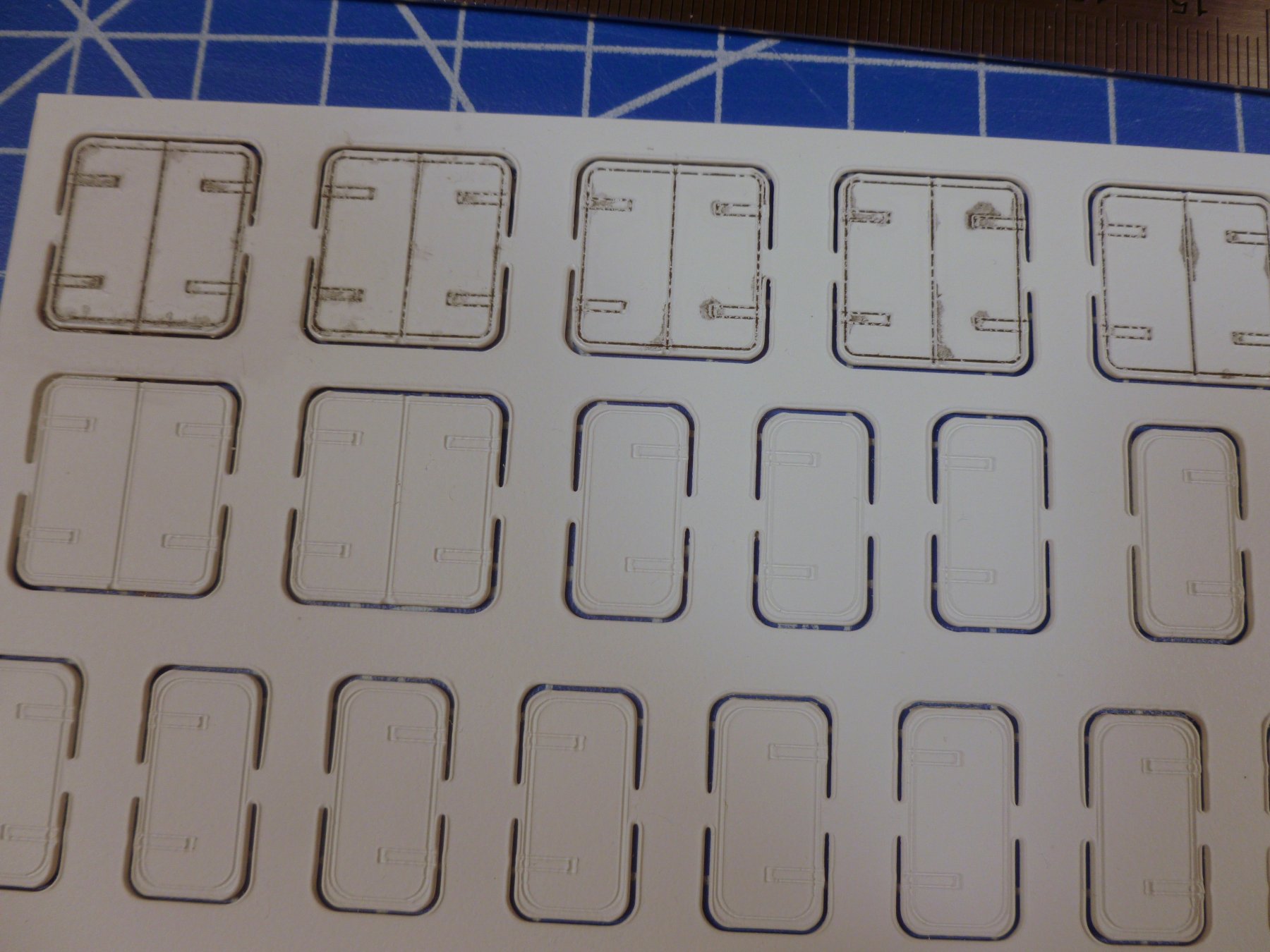
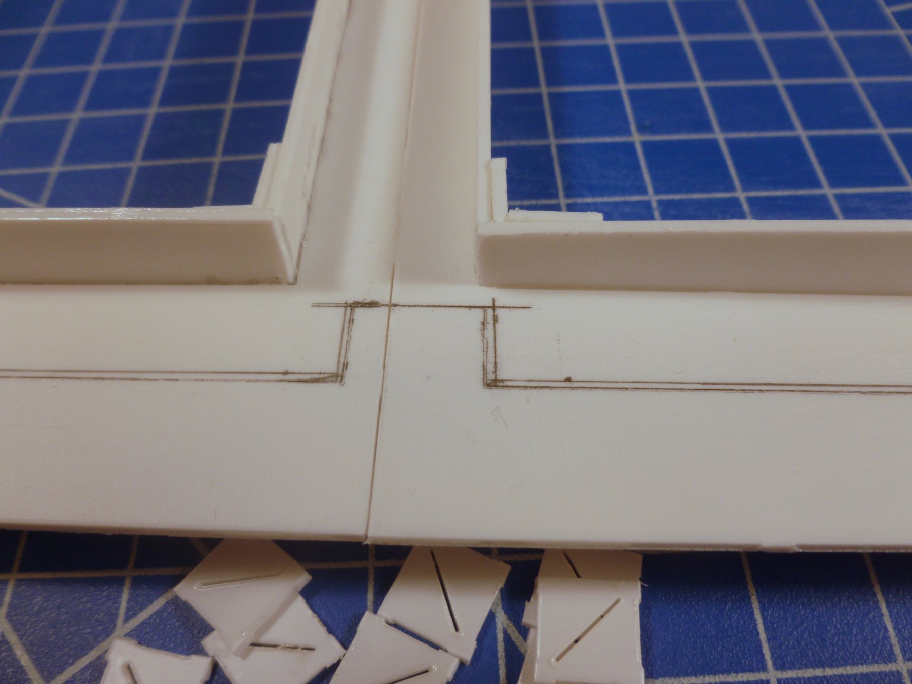
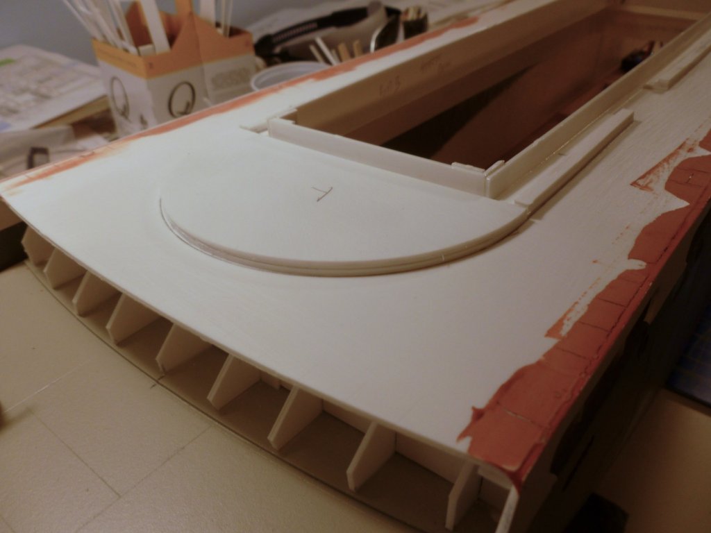
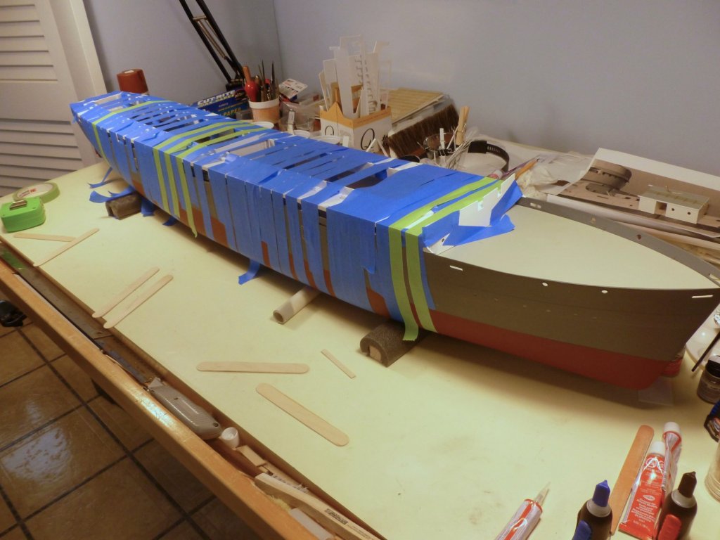
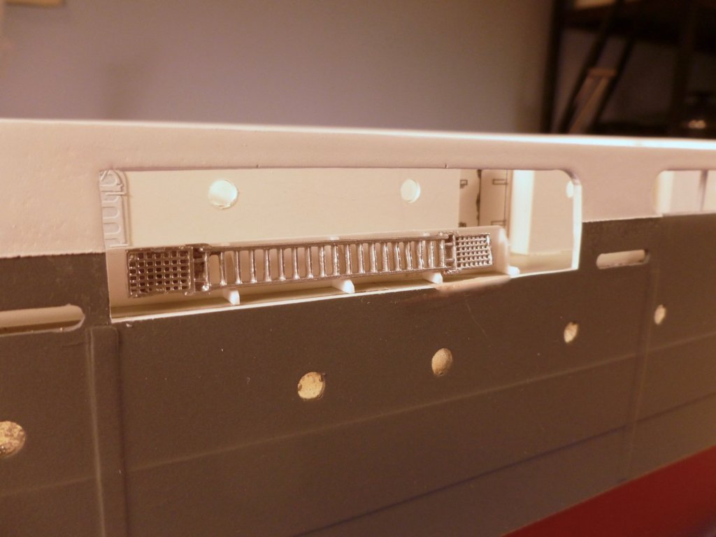
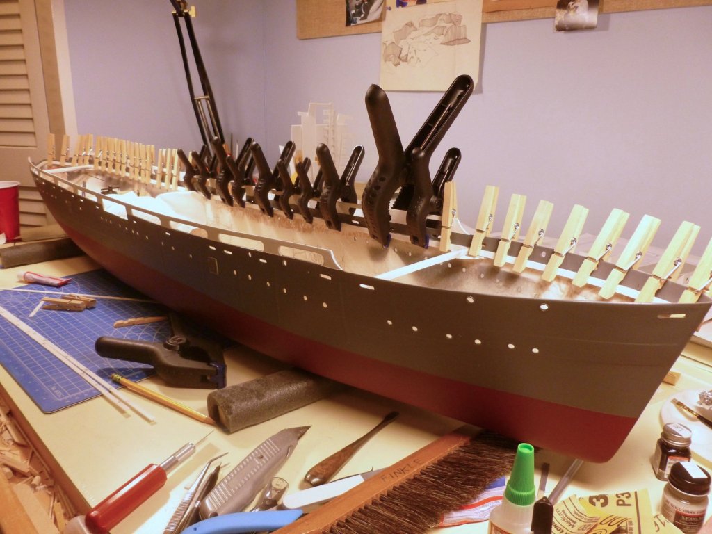
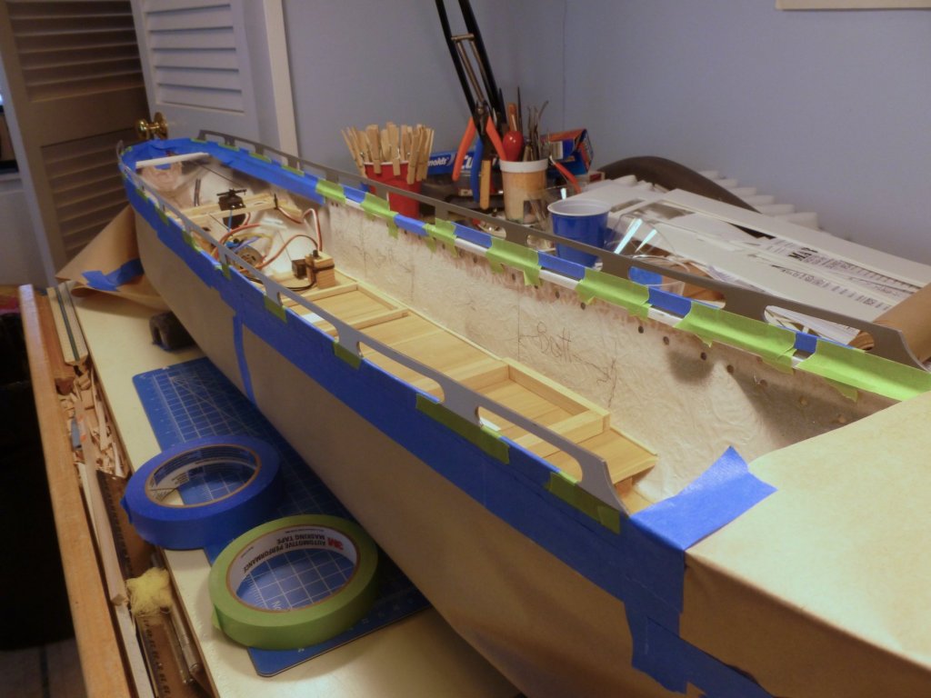
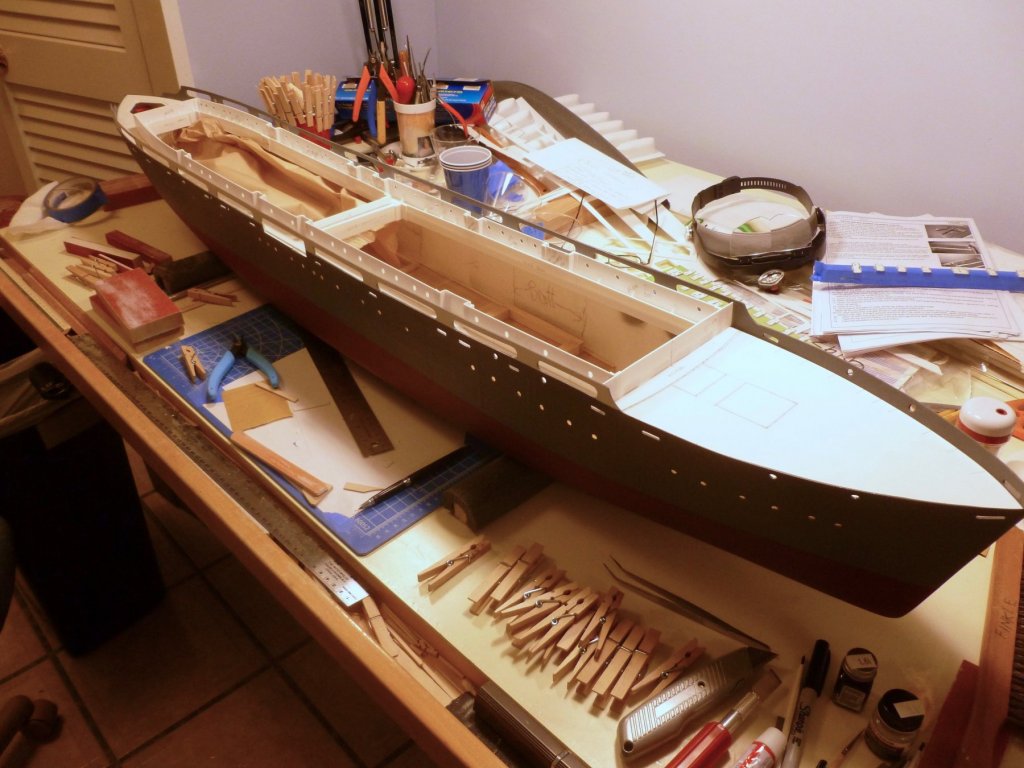
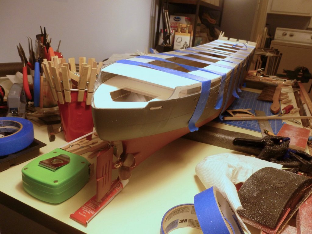
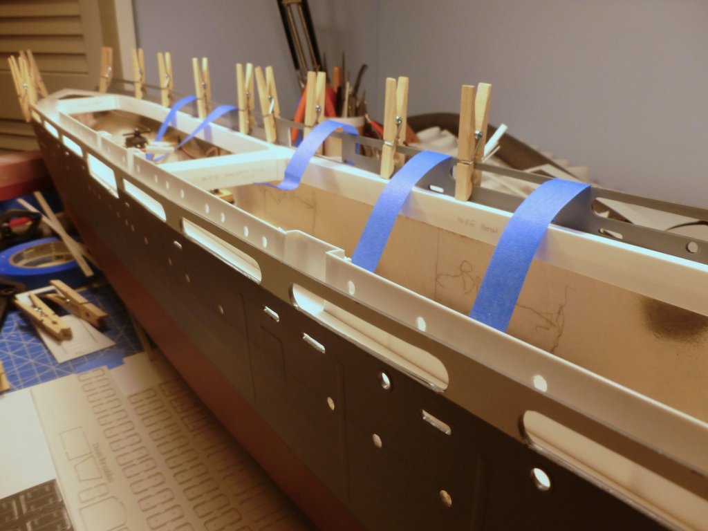
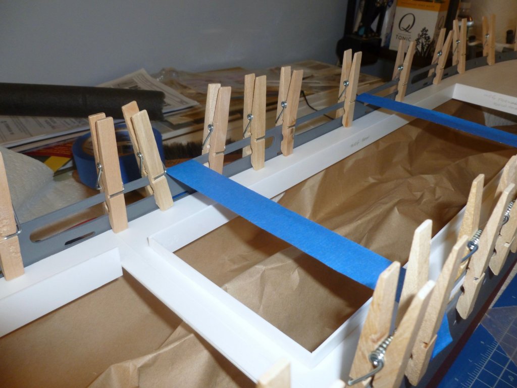
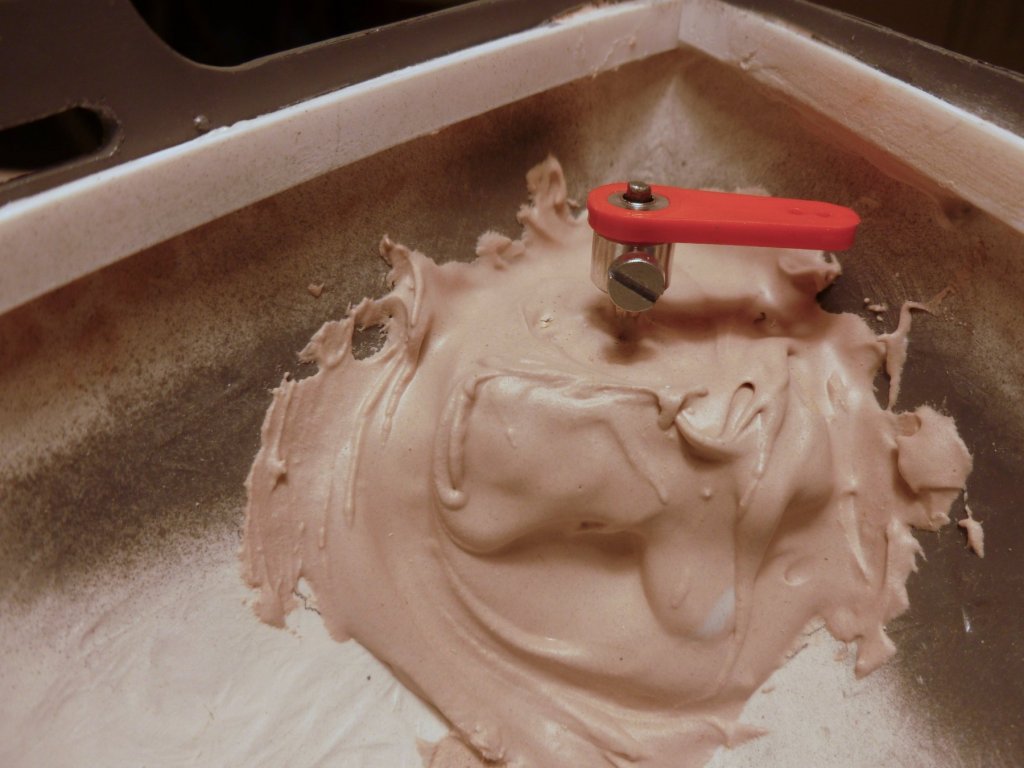
To those who gave likes, thank you and thanks for stopping by. Bill, thanks for your recommendation on vinegar. I'll put it to use when I get back to the railings. The accommodation ladders are installed, but there needs to be some housekeeping to remove dust specs. For the deck in the ladder area I wanted to use the same color as the hull but found out that the manufacturer only makes it in a spray can. I went online and found a method for “decanting” spray paint into a jar. Cover the jar with tape, slice a small hole in the top, insert a cut-down bendy straw in the jar, bend the top 90 degrees, hold the spray can nozzle up to the straw and spray away. The trick is to then let the paint in the jar sit for about two hours to let the propellant bubble out of the paint. And it worked. The paint was a bit thin when brushed, probably because I only waited about an hour, but several coats later there was a good color match. The patch needs a bit of fine tuning and some dullcote, but overall it seems a good workaround. Photos of the ship show an edging along the roofline of the Air Conditioning room so a bit of Evergreen strip was tacked place. Unlike wood the thin plastic takes a tight curve nicely. The room is just resting before final trimming and gluing, and the railing is awaiting its installation opportunity. Boat deck assembly was next, accompanied by much angst, hemming and hawing. The instructions call for building up the deck edge with two extra strips, and then CA-gluing the edge of the deck to the inside face of the promenade opening. The questions were how to support the deck edge while installing, how to keep the CA from setting up over two long joints, how to keep the CA from oozing out over the top, or worse down the inside, since the deck is a fairly tight fit, and how to clamp both sides at once. Oh the agony. The photo shows the deck under construction before the big moment. The plastic pipe maintains the deck sheer while it is inverted to add horizontal stiffeners to the hatch coamings, and to install the perimeter beams. Despite efforts to cut the promenade columns to the right height I discovered I needed to notch the deck beam at each location. A few columns popped loose when I was test clamping the promenade wall to the deck edge, and were duly reinstalled with medium CA on both sides. I contacted the manufacturer who suggested adding support triangles along the promenade walls. Combined with the brass columns this gave a nice bedding for the boat deck. The triangles are not visible from the exterior since they are located between the promenade openings. After some Dremel grinding to take the paint off the promenade wall at the joining line things were more or less ready for the boat deck placement. Then the lightbulb went on. The procedure was to run, and I mean run, a bead of medium CA straight from the squeeze bottle, along one deck edge, set that edge in place, insert some craft sticks flat under the other deck edge to hold the edge above the promenade wall, then clamp the first edge with a generous amount of blue tape fastened to the hull and to the hatch coaming. That started the bonding on one edge and bought time to run a second bead along the other edge, and work the deck into place, removing the craft sticks as I went along. The second edge was taped to the hull and coaming, and then a second layer of tape from hull to hull pulled the whole assembly tighter. The photos below show the trussed up hull, looking like a wrapped lump of meat, and the after view showing the boat deck ready for its beauty shot. Boat deck edge filling is underway, using autobody glazing putty, a one-part mix that is very fine in texture, but boy does it set up quickly. One side is wet sanded in the pic. The boat deck is the last deck that is permanently fastened. The boat deck cabins will be attached to the underside of the bridge deck, which allows the entire upper superstructure to be removed for access to the innards; so the boat deck requires a built-up curb to receive and stabilize the cabins. Flush with the success of the boat deck I gave myself a little R&R working on highlights for the PE watertight doors. Some good, some fair or not finished yet, lots more experience needed in the highlighting business.


- 446 replies
-
- 9
-
-
- zebulon b vance
- deans marine
- (and 3 more)
-
very nicely done. A terrific level of extra detail.
-
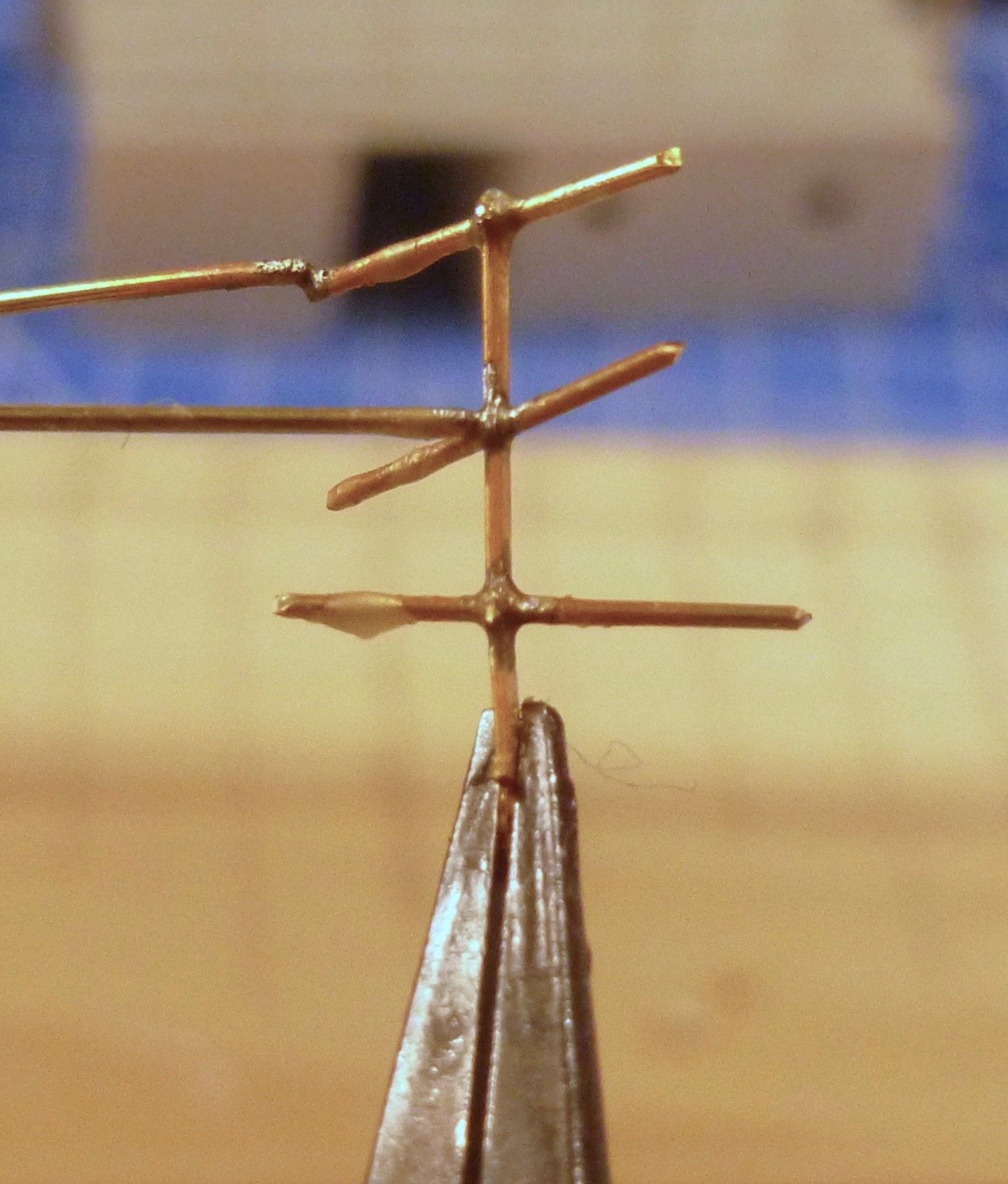
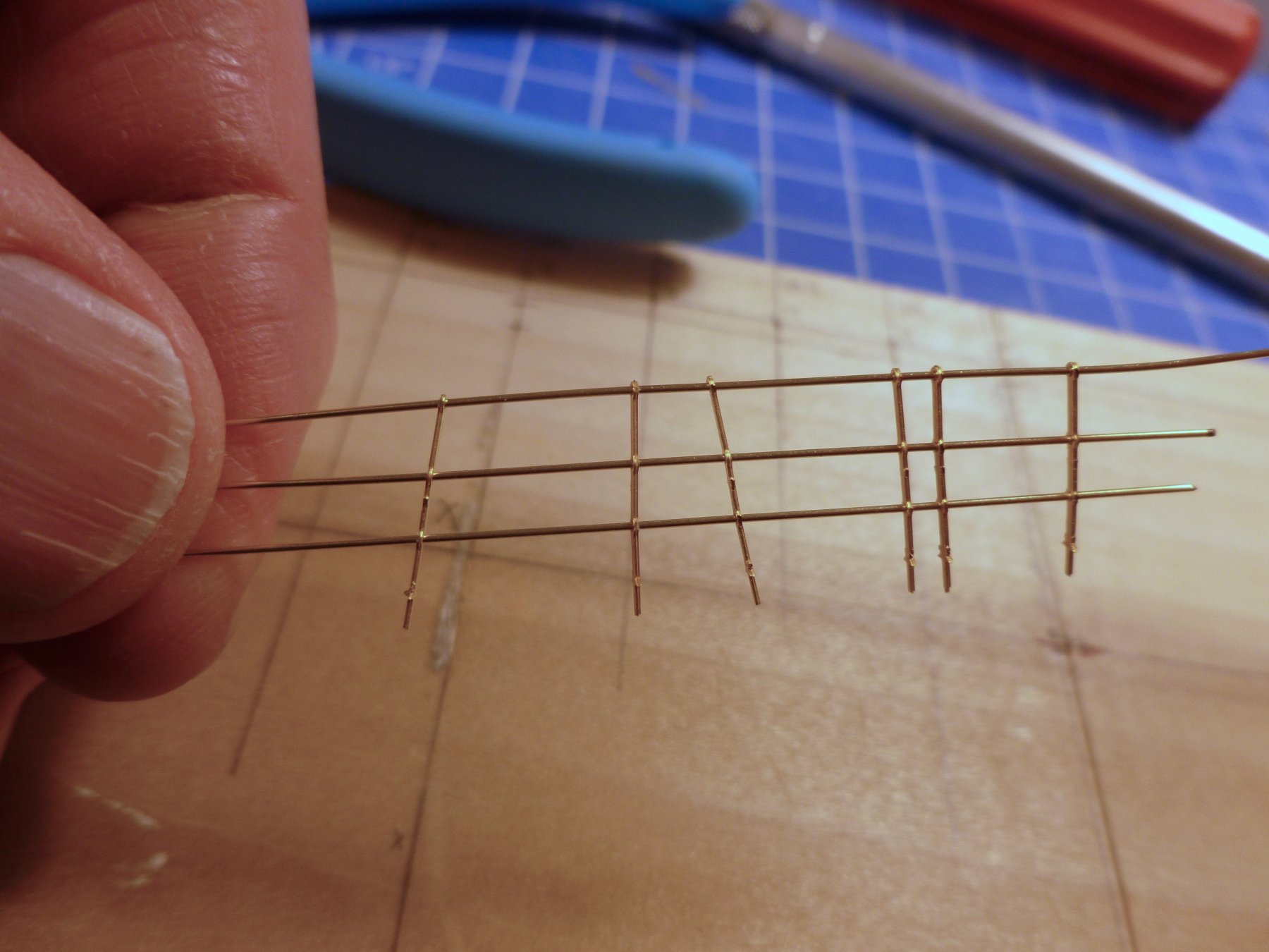
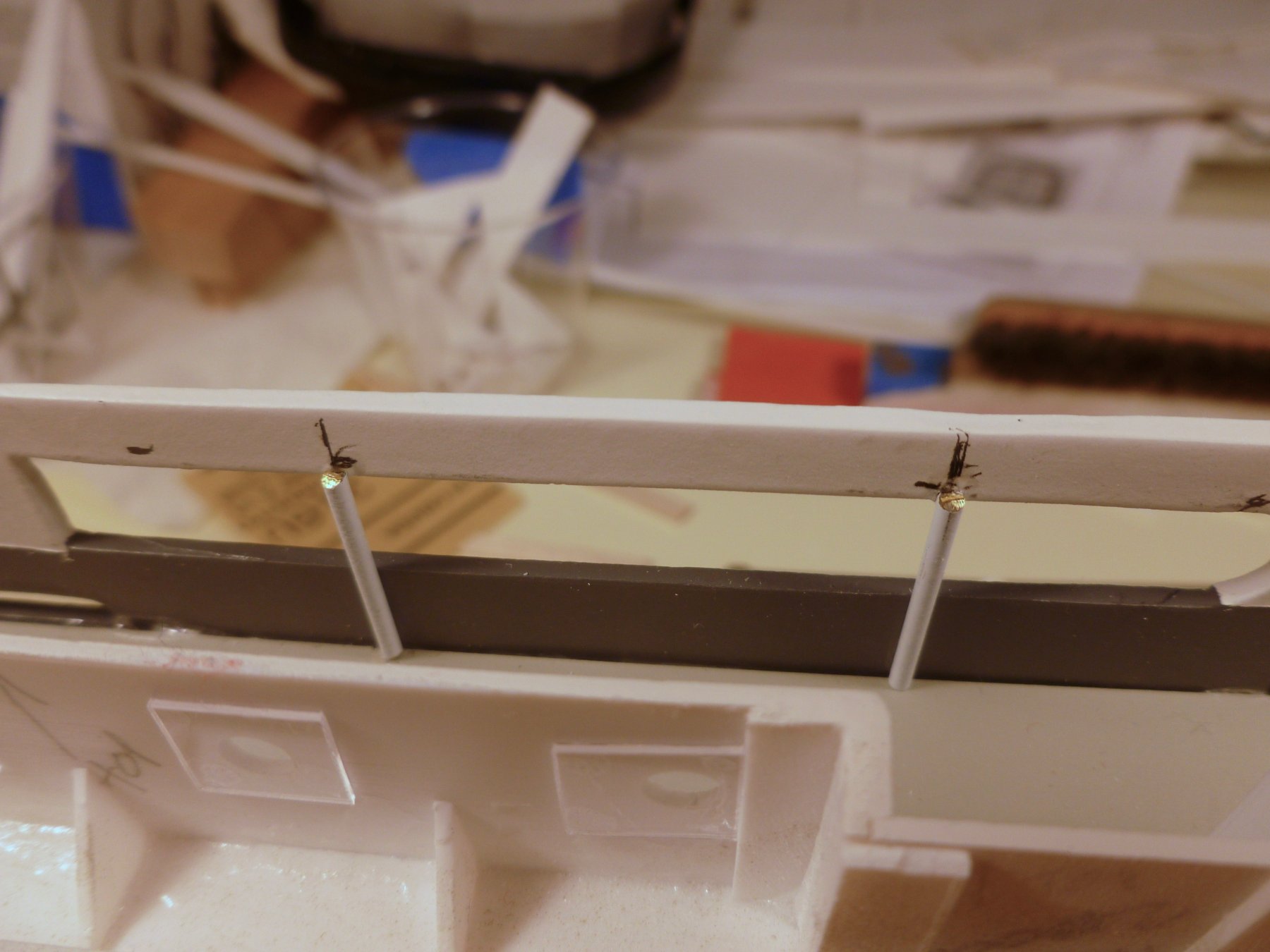
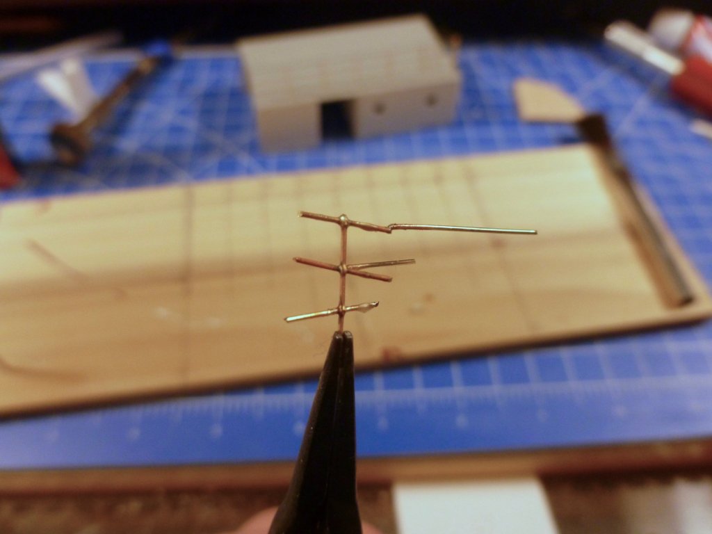
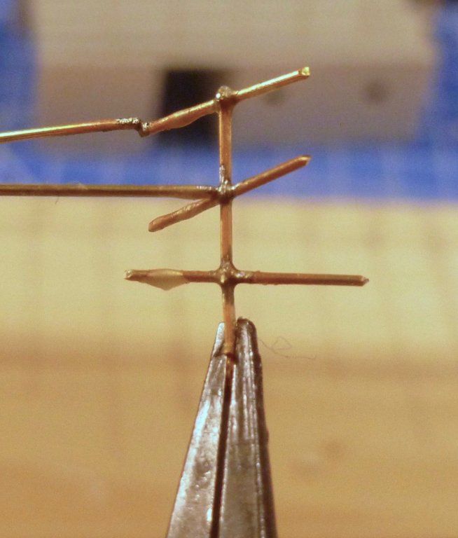
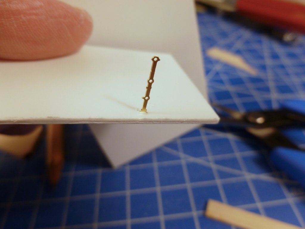
To those who gave likes, thank you and thanks for stopping by. Bill, welcome and thanks for the suggestions. It’s never too late for me to learn anything. Interestingly, when I went to a piano store to look for some wire needed early in the build, the proprietor went in the back and cut it off a roll. He said it would straighten out but it seemed like you would need a piano on both ends to keep it taught. Later on while walking through my LHS I discovered a box with all sorts of straight wire. I picked up a few bits but I’ll need a lot more to cover all the railings on three decks. My experiment used wire that came with the kit. Stretching it between a vice and pliers straightens it pretty quickly but I don’t think there will be enough to do the entire ship. I’m feeling appropriately chagrined about my suggestion to leave the brass unpainted, so I’ll probably cave in and paint it. My only choices are rattle can or brush since I don’t have an air gun. What do you use to clean assembled wires before priming? Carl, I’ve decided to drill and fill, rather than heat sink. I’ve ordered up a stash of drill bits to match the stanchion dimension. I’ll probably use medium CA since the stanchion is flat but the hole is round. Kevin, thanks for the suggestion on using a single primer coat. I guess the question is whether white primer would yellow over time. Steve I bit the bullet tonight and decided to see if my pipe soldering experience could translate into working with teeny tiny wires. I stuck some wire bits into a stanchion, blobbed on a little flux, touched the 30 watt solder iron pointed tip into a minuscule bit of solder to tin the end, and voila! The solder sucked into the stanchion/railing connection just like doing the big pipes. The photo is immediately after soldering, with no effort to wipe the joint or remove excess flux. Emboldened I tried end to end solder on a railing. Almost had it but I didn’t hold the free hanging railing long enough to let the solder set up so it ended in a jig-jag. But I know I can do it. I also tried adding a third leg to a soldered fitting and that worked too. And I didn’t even have finger-frying collateral damage. It takes me awhile guys, but with your encouragement and guidance, at least I feel I’m at the entry to your playing field. Hope you have a productive weekend. Thanks.
- 446 replies
-
- 8
-
-
- zebulon b vance
- deans marine
- (and 3 more)
-
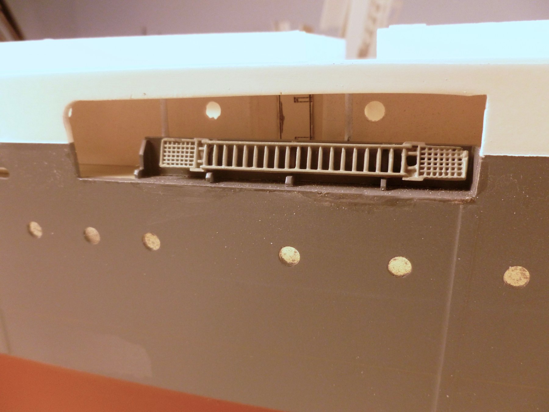
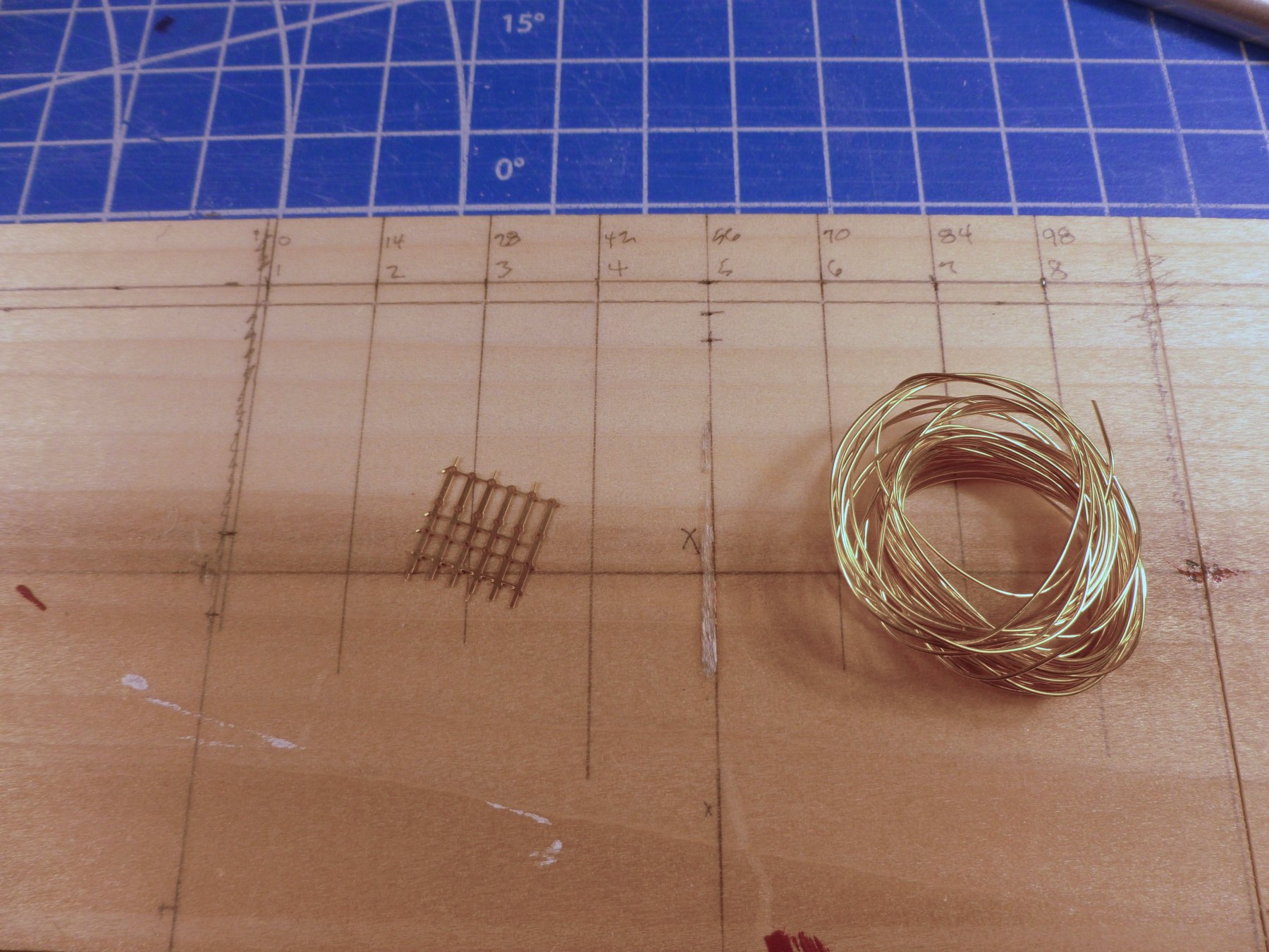
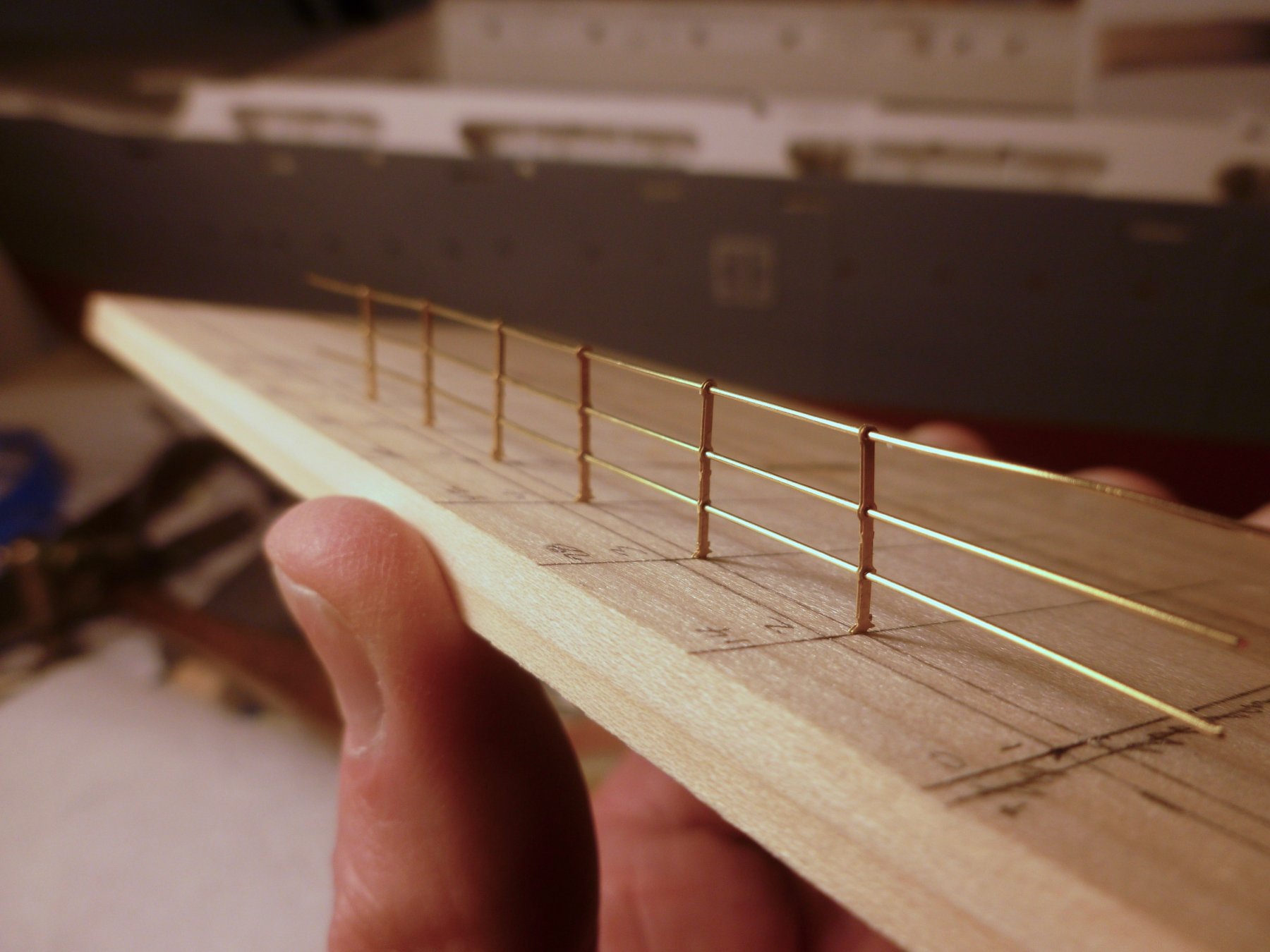
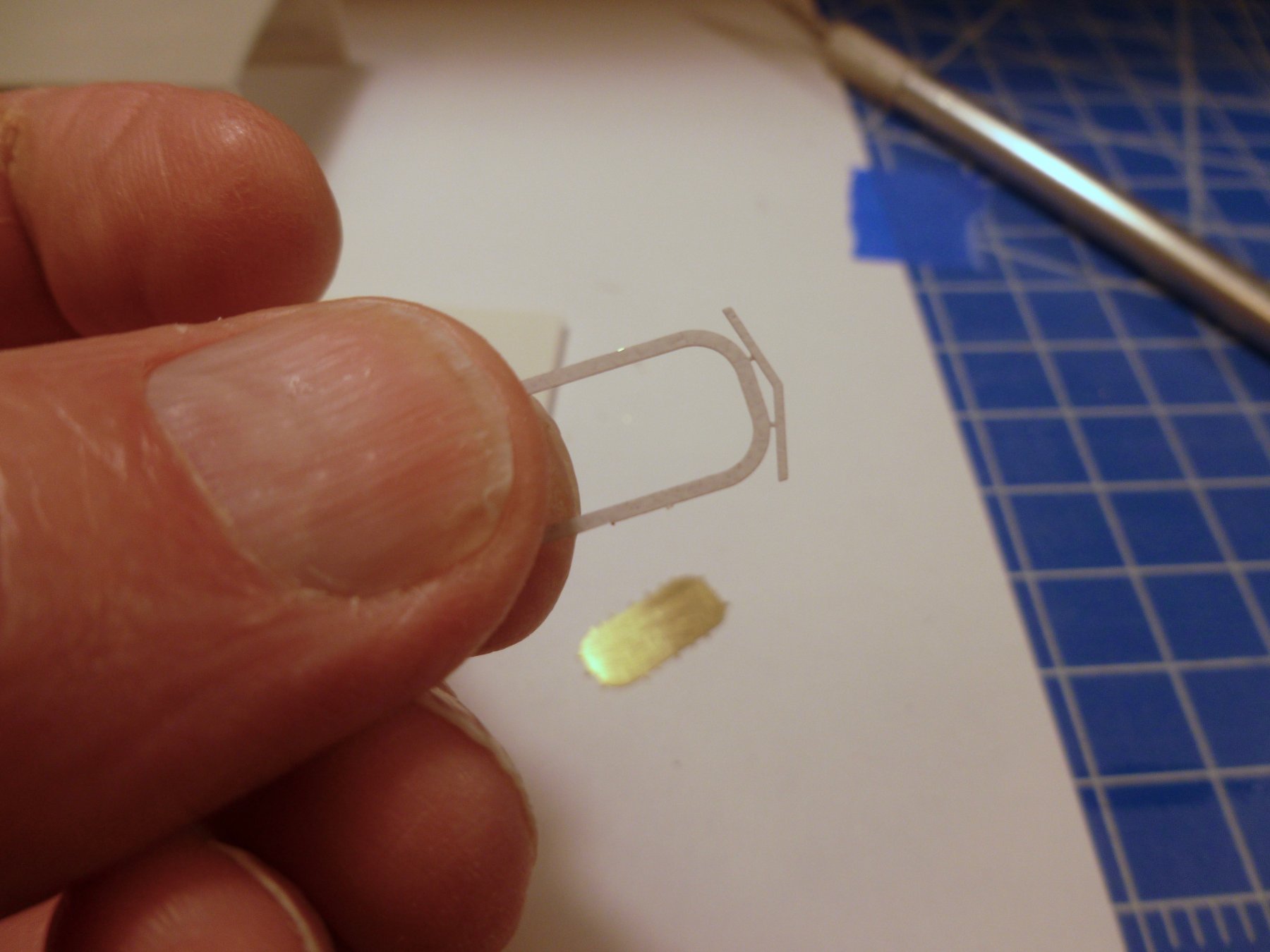
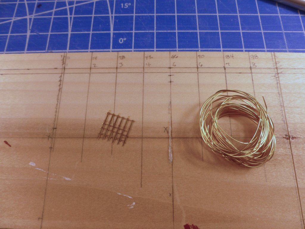
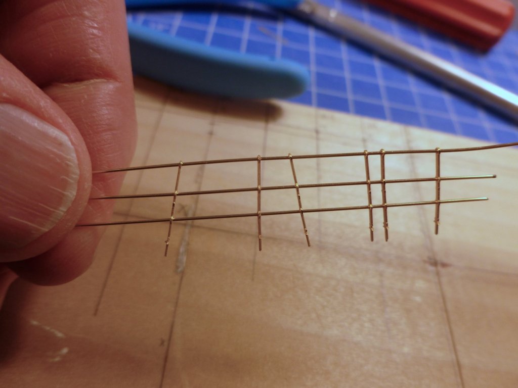
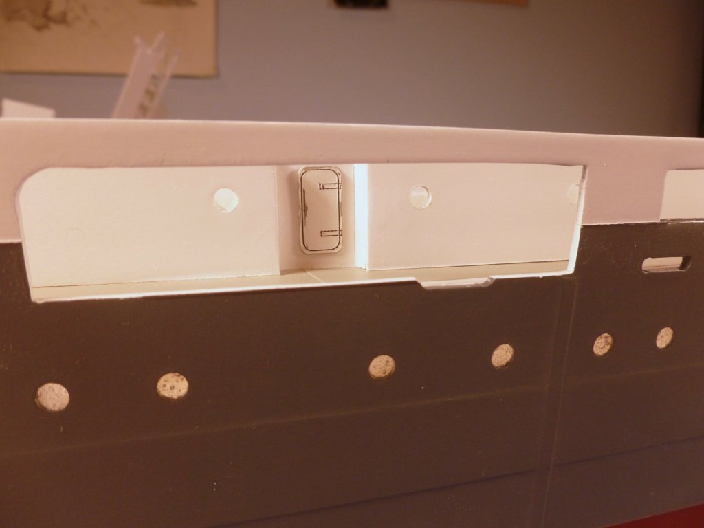
To those who gave likes, thank you and thanks for stopping by. Carl, thanks for the styrene suggestion. I recently purchased some Evergreen flat strips at the LHS for misc trim work, but hadn’t thought of styrene rod for posts. I guess it’s my architectural background - whenever I think posts I think metal pipe. Steve There are no details for the accommodation ladder recesses on port and starboard so I fabricated them based on the blurry closeup of area on the Vance in her hospital mode shown in the earlier posting. The first try was clunky, too thick, too deep and too tall. The second was better and is now in for painting. Still haven’t finished filling in the divot at each recess. The ladder is a kit part. From what I have seen in articles it appears the accommodation ladders had a grating platform at each end that tilted to remain flat. The ladder itself was installed in position using a small crane or other lifting device, and handrails either snapped into place or were placed in sockets along the stair stringers. I decided to take a crack at some railing assembly. Above is a jig and railing parts. I stretched the wire to stiffen it. I started out trying to saw grooves into the wood to take the stanchions laying down, but quickly abandoned that idea in favor of a more workable set of drilled holes in which to set the stanchions. I actually started out trying to use an exacto knife to cut slots in the wood, but abandoned that after the no. 11 blade tip snapped off in a few spots, which forced me to re-establish the layout line. As it turns out the flat stanchion is held reasonably well in a drilled hole. I threaded the top railing into one stanchion, then added all the other stanchions. Before spreading them out I stacked them together and found that the holes lined up well enough to push the second and third rails through quickly. Then it was just a matter of spacing out the stanchions to align with the layout holes in the jig. For this short section I applied a drop of CA to each railing/stanchion connection. it seemed to stiffen it up pretty good. Between the success in drilling the layout holes and the clean look of a CA’d railing I’m reconsidering the whole railing experiment. At the moment I'm leaning toward drilling the deck at each stanchion location, and using CA to anchor the stanchions and make the connections, in lieu of heat sinking and soldering. That would help immensely if I choose to pre-paint the railing assemblies before installing them. But I’m also thinking about leaving the railings unpainted. They look quite elegant, at least to my eyes. Even though they would be historically incorrect would a clean, simple appearance be preferable to adding blobs of solder and layers of primer and paint? Biased opinions and heated debate are welcome. Take sides and take no prisoners.


- 446 replies
-
- 9
-
-
- zebulon b vance
- deans marine
- (and 3 more)
-
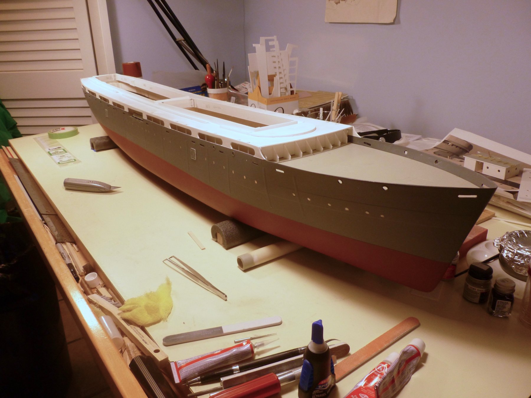
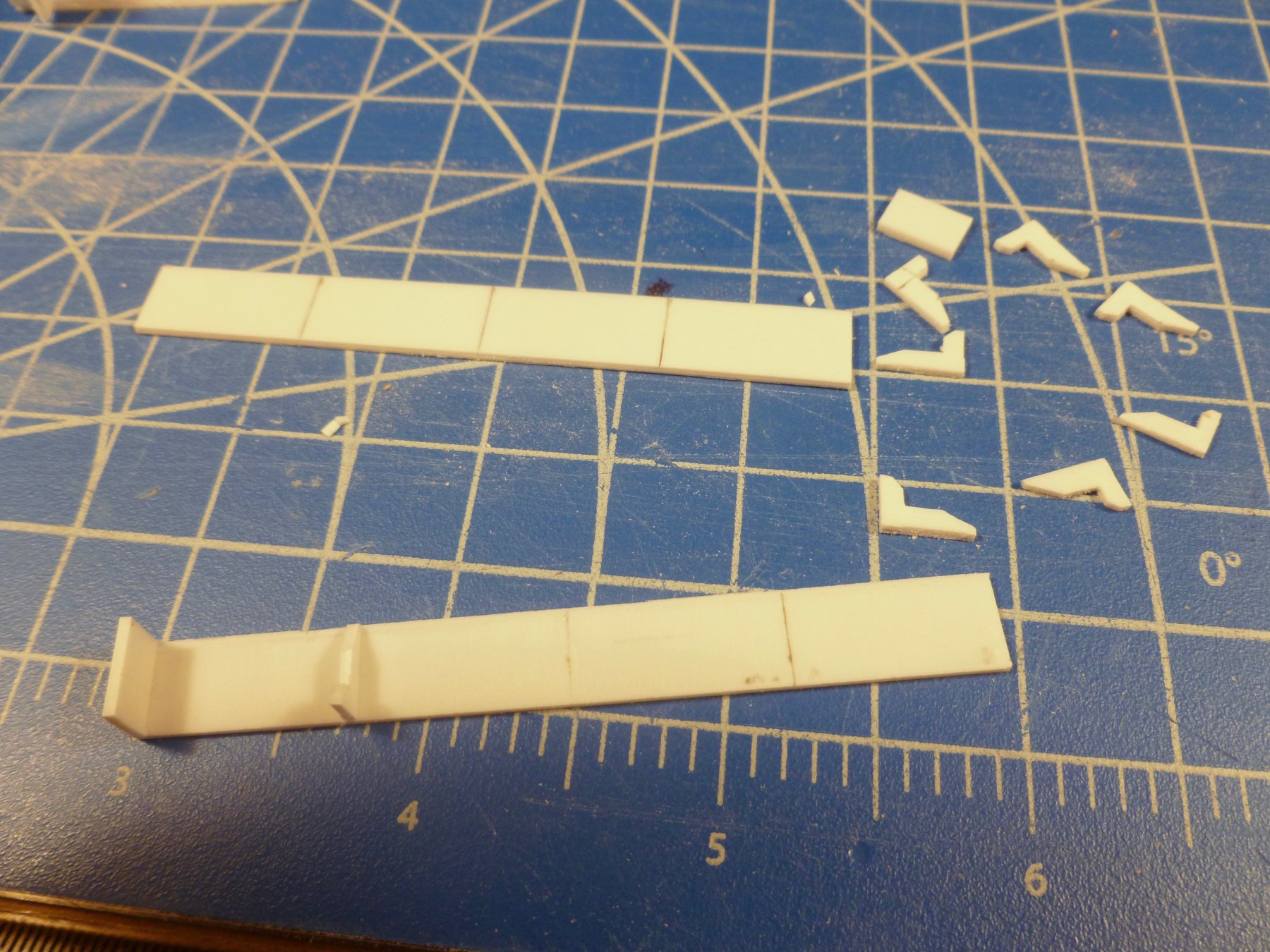
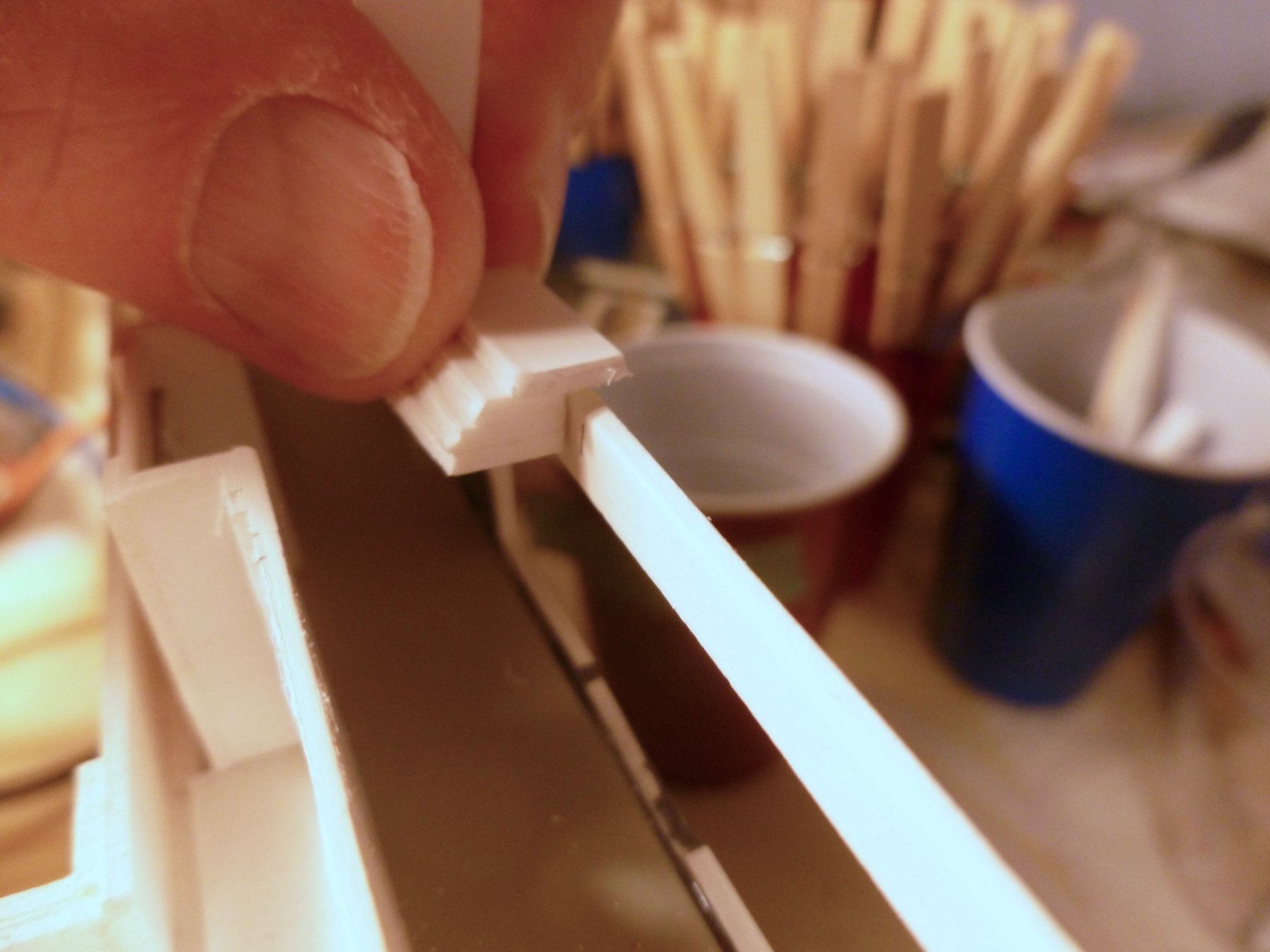
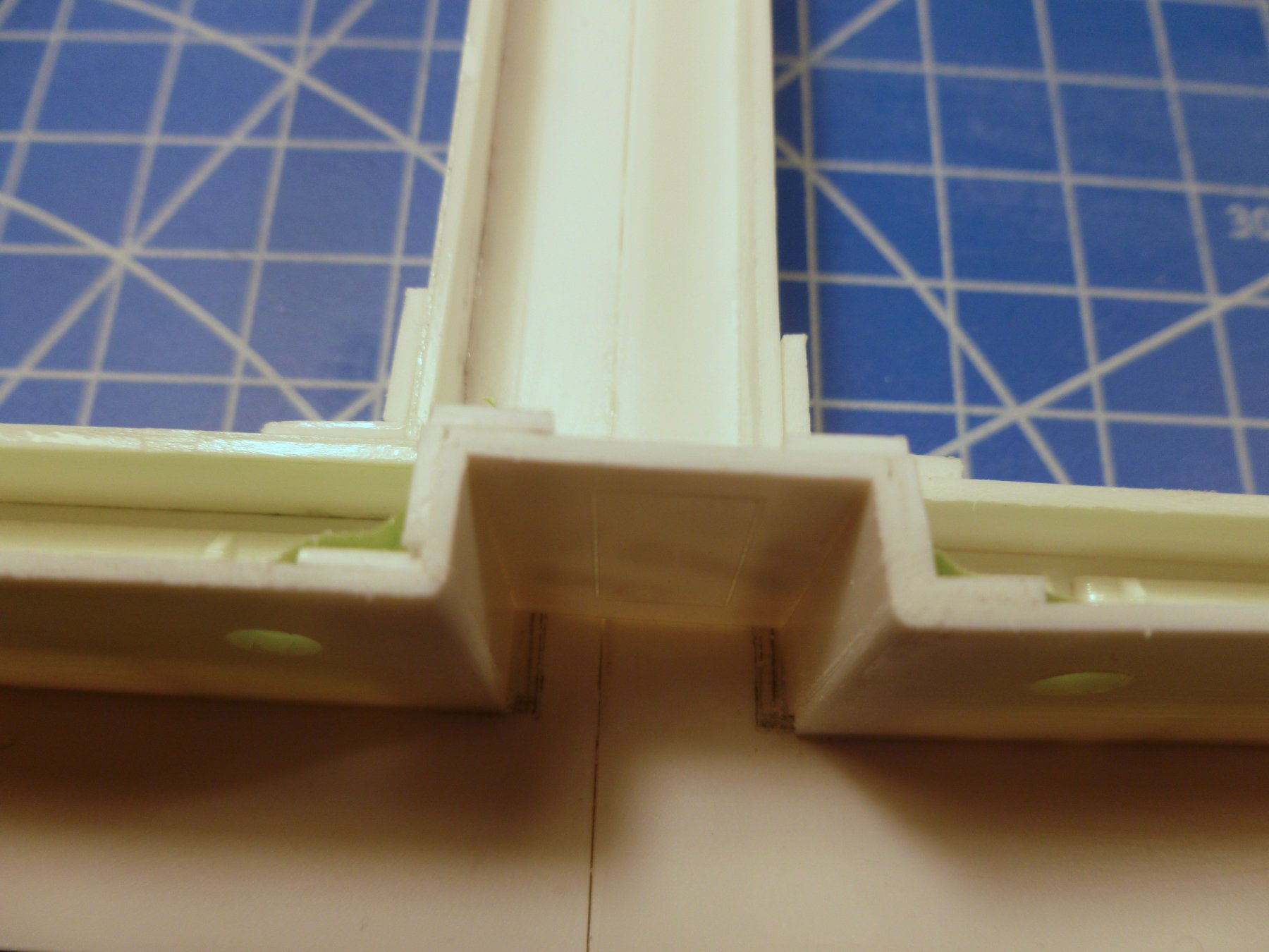
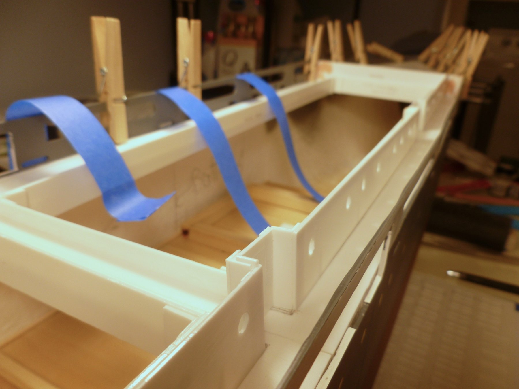
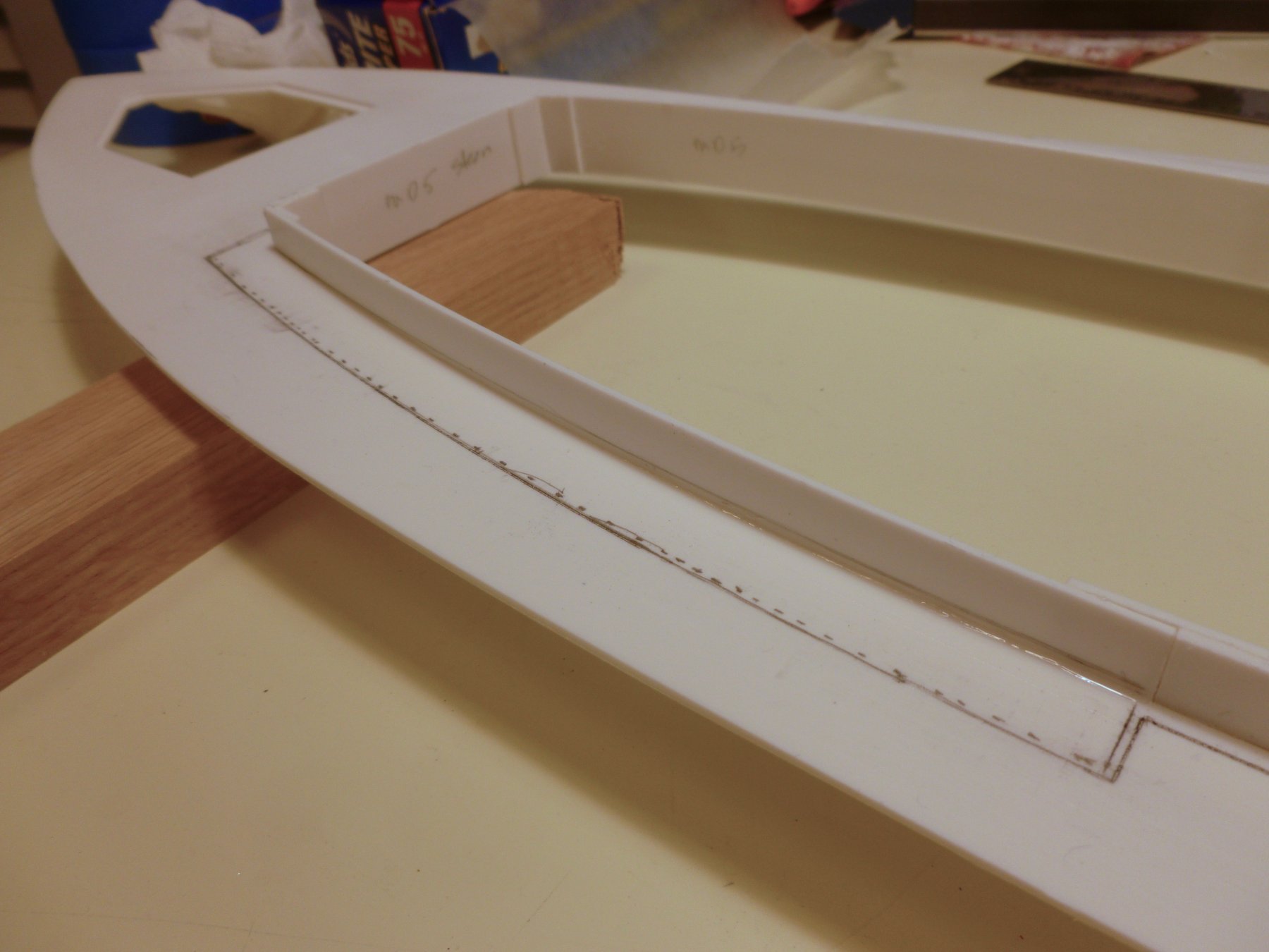
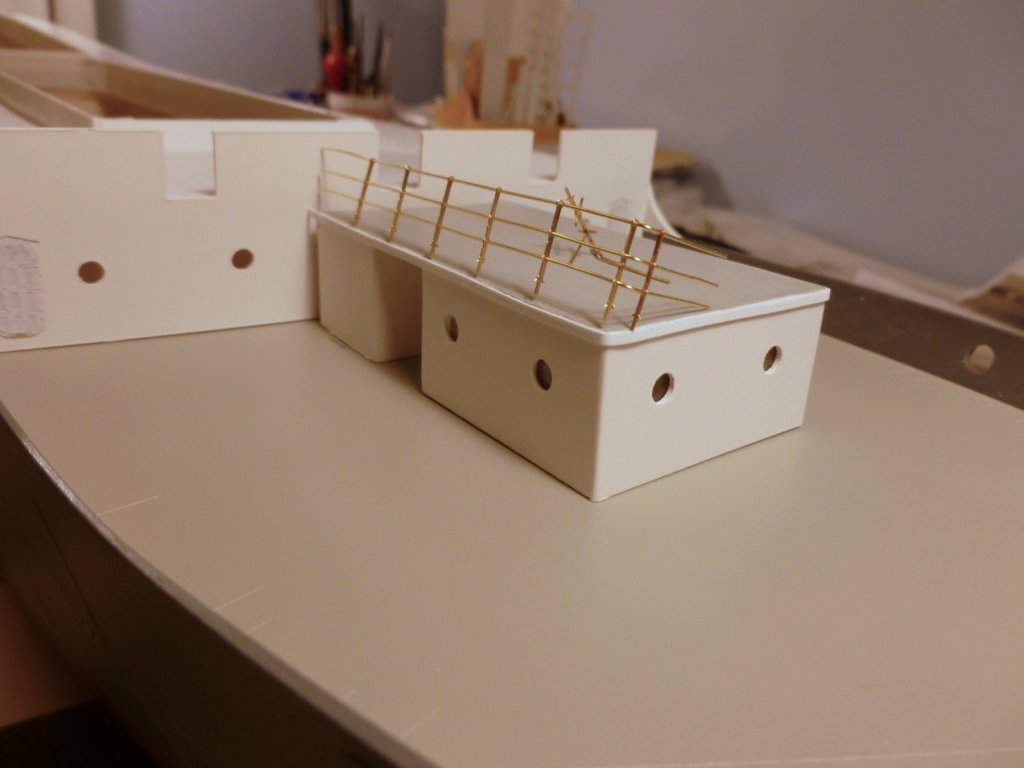
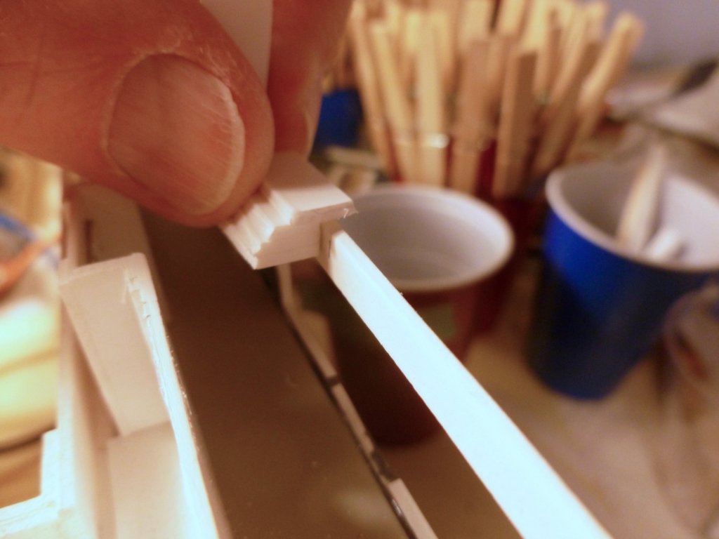
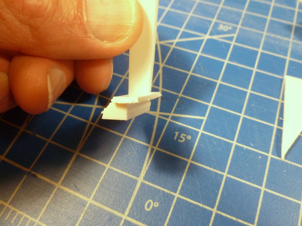
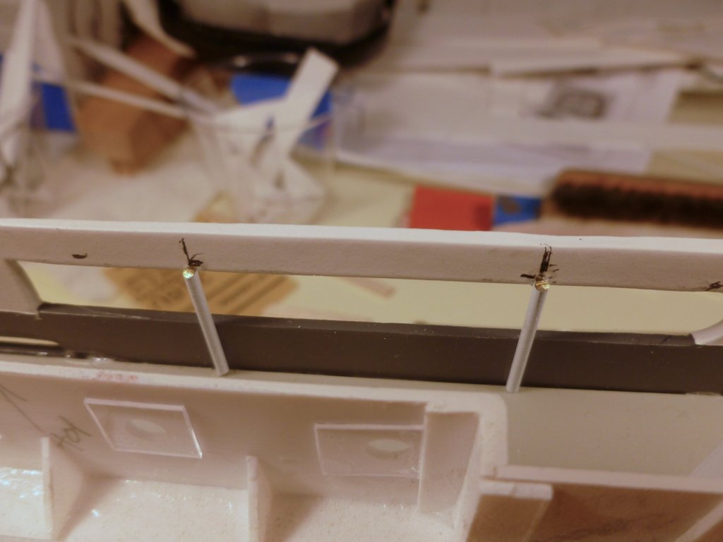
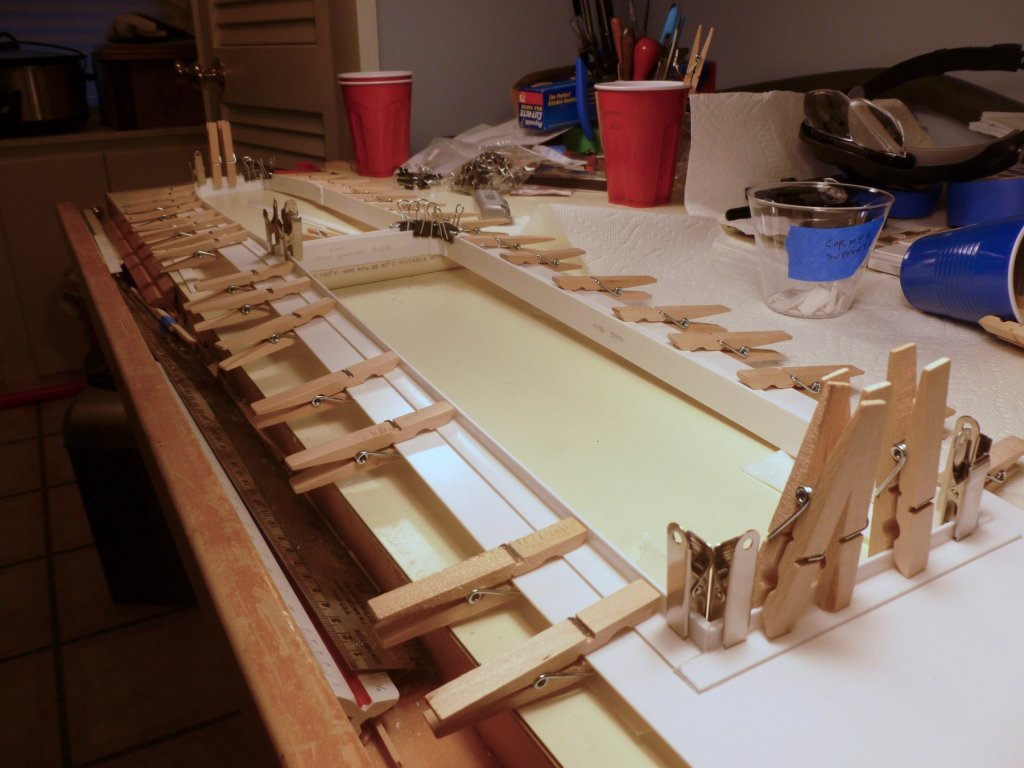
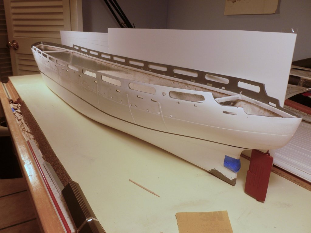
To those who gave likes, thank you and thanks for stopping by. Steve The deck to hull marriage was a success. The honeymoon is over and the next step is installing perimeter support posts for the boat deck. In the model they don’t actually support anything since the boat deck sits on the first floor cabin walls and is glued to the inside face of the main deck promenade wall. The kit says to cut flat strips off the PE carrier sheet to simulate the posts, but since photos look more like round posts I decided to cut them out of brass rod. The question was where to terminate them at the top since the boat deck gets two strips under its outer edge to act as a perimeter beam and to provide more gluing surface. I made a little jig, with three strips equal to the boat deck/beam thickness, a fourth strip to sit on top of the promenade wall, and a vertical strip to act as a handle. It made quick work of locating a line in each post location to set the post cut off height. Action photo below. The posts were fixed to the promenade wall with thin CA. Some promenade openings sanded out a bit high (or the top of the promenade sanded too low), leaving very little area for gluing the top of the post. I added some medium CA along the lower portion of the posts to strengthen the installation. It just occurred to me that after carefully masking and painting the inside top of the promenade wall I have to sand it down to give some bite to the boat deck edge gluing.... The only part of the post that is visible is the exposed surface at the promenade opening. The exterior view is below. I shifted the work lights to throw a little shadow at the post tops.

- 446 replies
-
- 7
-
-
- zebulon b vance
- deans marine
- (and 3 more)
-
I just completed a breathtaking ride through your magnificent build. There is such a wealth of detail that it would take hours and hours to fully enjoy it in person. I shudder to think what you would do at a larger scale - my guess is everything would work! Congratulations and happy holidays. Thanks for taking time to share your skills and techniques. Steve
-
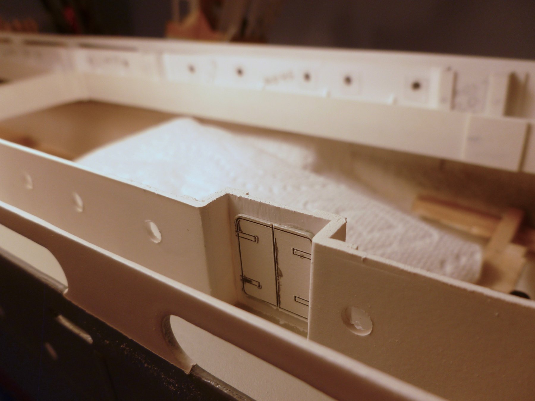
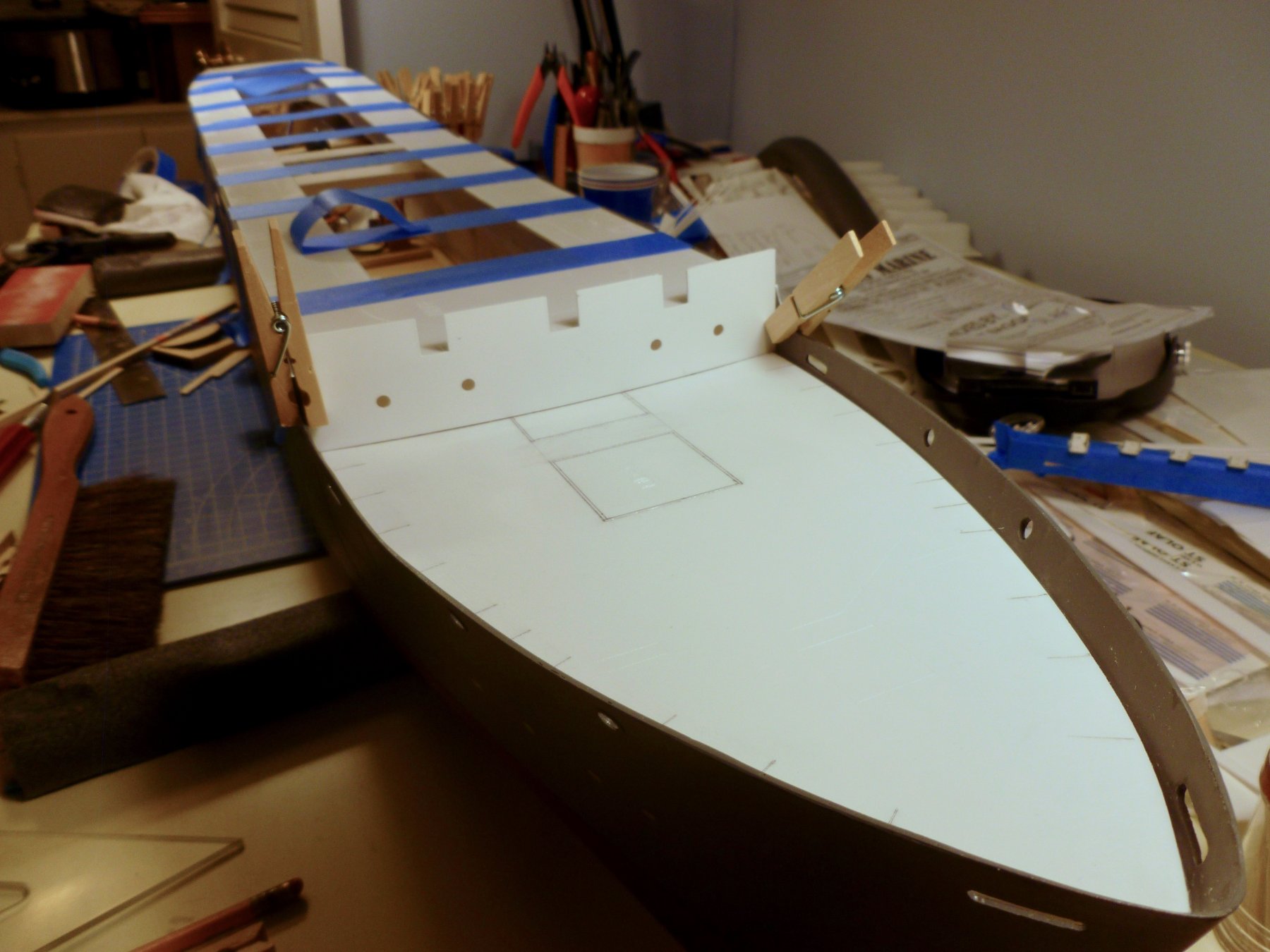
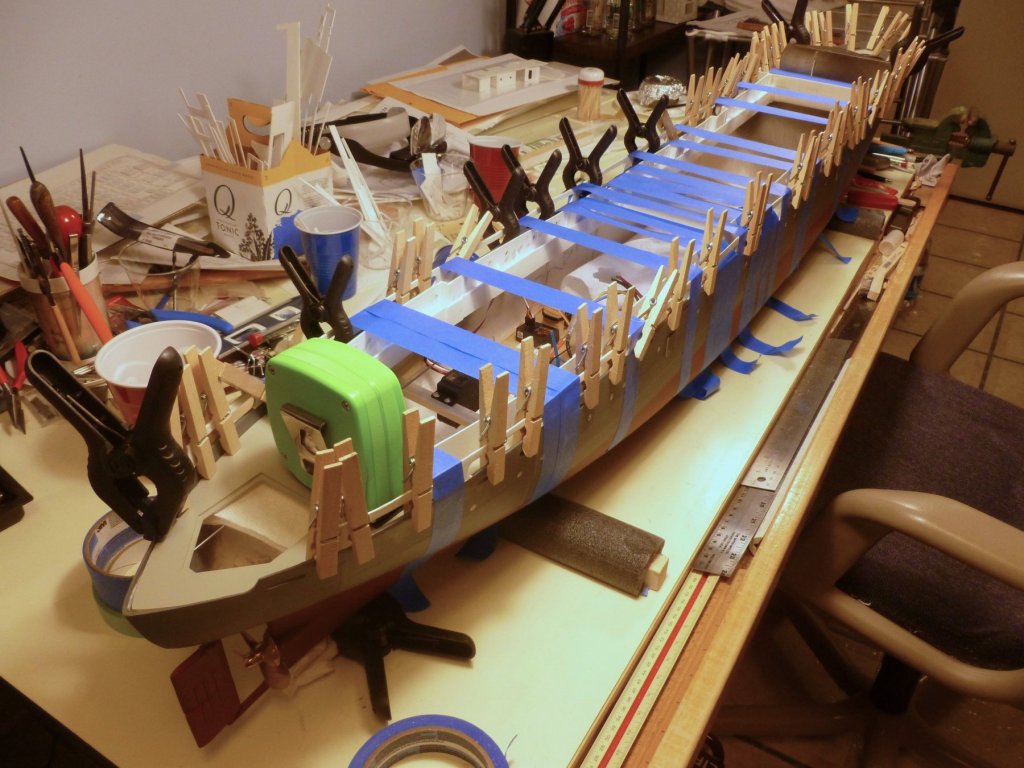
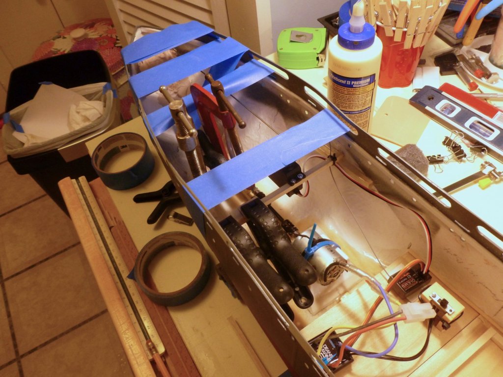
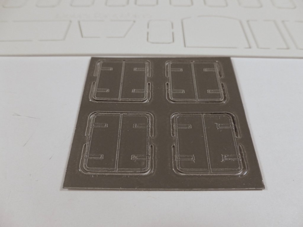
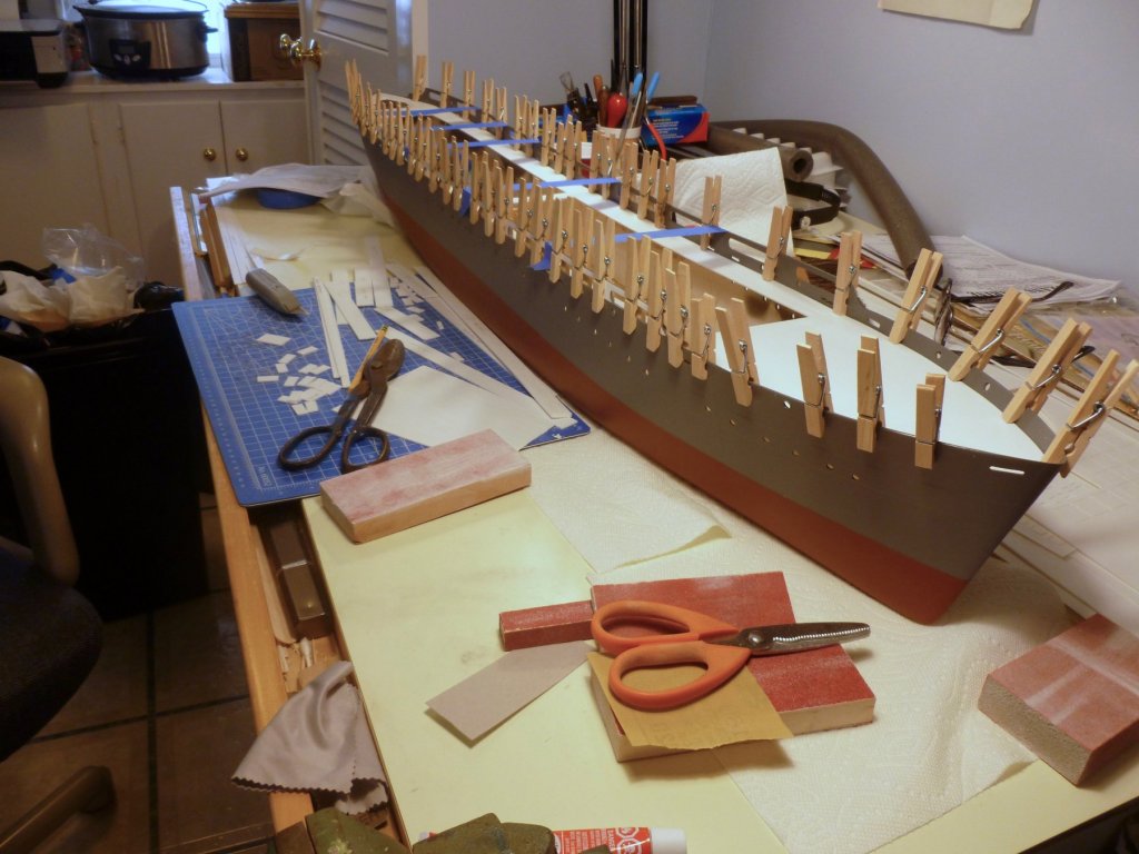
To those who gave likes, thank you and thanks for stopping by. Carl, unfortunately I have become well versed in paint pulling, I think partly because of rushing a bit between coats, or having insufficient dry time before applying masking tape over the new paint. I don’t have an airbrush but I’m leaning toward installing the railings and stanchions naked, and painting after. Lou, thanks for your input. The ladder in the Meany picture looks to be a bit more than just a ladder, perhaps a portable version of a ship’s ladder with inclined steps? The notch in the bulwark is actually the bottom half of a scupper that I had cut in before cutting down the promenade bulwark to deck level. I’m planning on filling it in while working on the inside bulkhead. Steve In anticipation of the upcoming marriage between the main deck and hull I added another layer to the perimeter deck beam, giving a more substantial bearing surface. The PE sheet of watertight doors and frames arrived from Tom’s Modelworks, very timely shipping even without considering the holiday mail traffic. The sheet is well detailed, with setups for open and closed doors of several different types. The closed door, shown here with a dusting of primer and topcoat to preserve detail, but without final trimming of sprue, has appropriate dogging. The open door configuration, which I tried out on the main deck locker, moves the dogging onto, and parallel with the frame. With the main deck doors in place it was time to march down the aisle, holding my breath as the deck and hull said their vows. A bit nerve wracking considering there is over 3 meters of glue line to place, followed by setting the deck, pulling in both hull sides with yards of tape (more metric/imperial crosstalk), and applying downward pressure with clothes pins and anything else at hand. Hopefully it’s a productive honeymoon, with full bonding in a few days.

- 446 replies
-
- 9
-
-
- zebulon b vance
- deans marine
- (and 3 more)
-
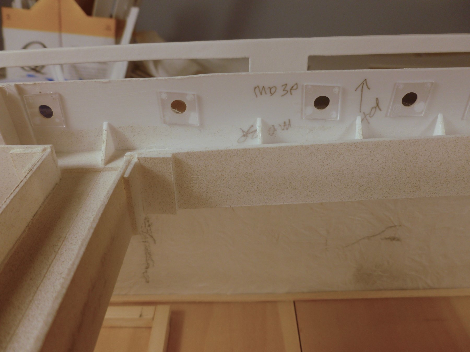
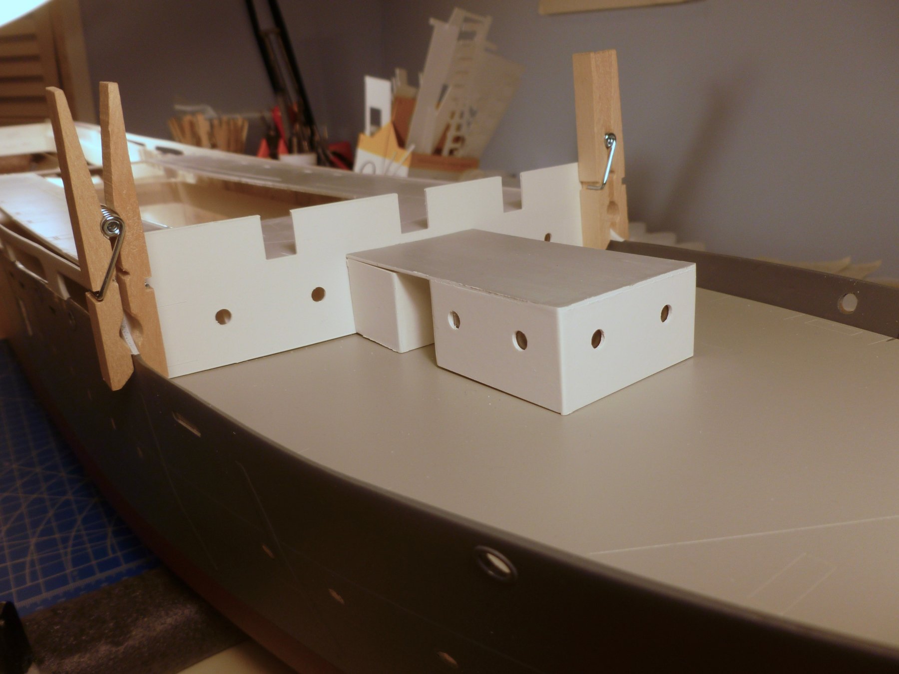
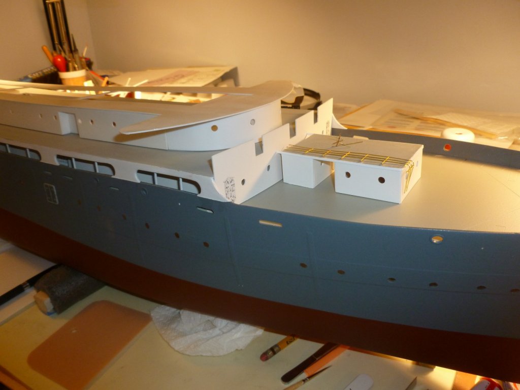
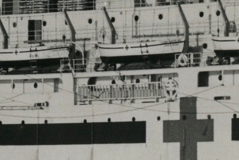
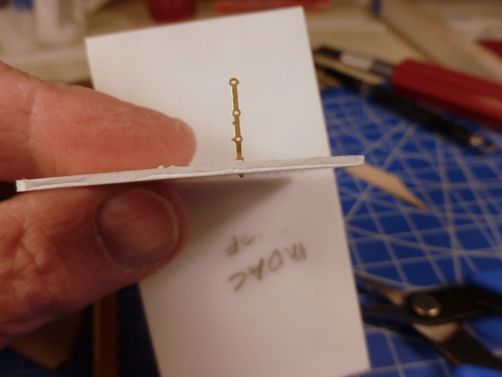
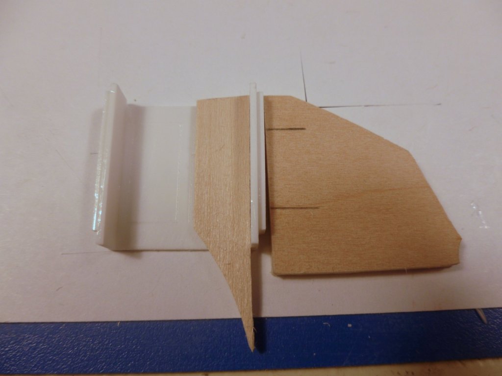
To those who gave likes, thank you and thanks for stopping by. Lou, Carl and Mark, thanks for your insight and suggestions. My first real opportunity to test will be the roof of the MDAC rooms (Main Deck Air Conditioning) which I am working on. The railing goes around three sides of the roof. Part of me wants to paint after the railing is installed. I’m unsure of whether I can be as clean and un-drippy as will be needed, but it would be very nice not worry about paint when I am soldering. Stay tuned on that. Steve I took a break from stanchion heat sink testing and installed the cabin doors at the main deck. After discarding the kit watertight doors (different from the cabin doors) I ordered a PE sheet of them from Tom’s Modelworks and hopefully they’ll be here in a few days. From what I can tell the main deck has a watertight door the starboard promenade, two at the MDAC (Main Deck Air Conditioning Room), two along the forward wall on either side of the MDAC and one at the MDL (Main Deck Locker, aft of the cabins. There are more on the upper decks. The pic shows the kit cabin doors which I have retained. I installed the glazing for the main deck portholes, which consists of 10x10 mm clear acrylic squares glued to the backside of the portholes. Noth ing fancy but it gives a spot of brightness and reflectivity at each porthole. Aft of the main deck forward wall is a support wall for the boat deck. On the aft face of the support wall I added shims to fully engage the wall with the main deck hatch cross beam, and at the forward face I added plastic triangles for additional support. The second pic is the same view with the forward primary wall temporarily set in place, and the MDAC rooms being test fitted. The forward wall has a slight curve and the MDAC roof must be scribed and sanded to it. Above are two pics, one from the model and the other a blow up from the Vance in its John J. Meany hospital ship configuration, courtesy of the National Archives. Both views show the starboard boarding area opening in the promenade bulwark. Now that I have cut the promenade wall down on port and starboard sides I have to figure out the infill to match the NARA photo. There appears to be a recessed wall about 4 ft high, with four vertical supports along the outer face. The supports look like they are shaped to do double duty as a rest for the boarding ladder (?). So far, so good. I’m guessing the low wall stops toward the forward (right) end of the recess, but I’m wondering if anyone knows what the thing is adjacent to the ladder. Is it a small raft? How would the ladder be deployed? Would it just be untied and dangled over the edge for pickup by someone on the dock, or is it attached to some rigging?


- 446 replies
-
- 6
-
-
- zebulon b vance
- deans marine
- (and 3 more)
-
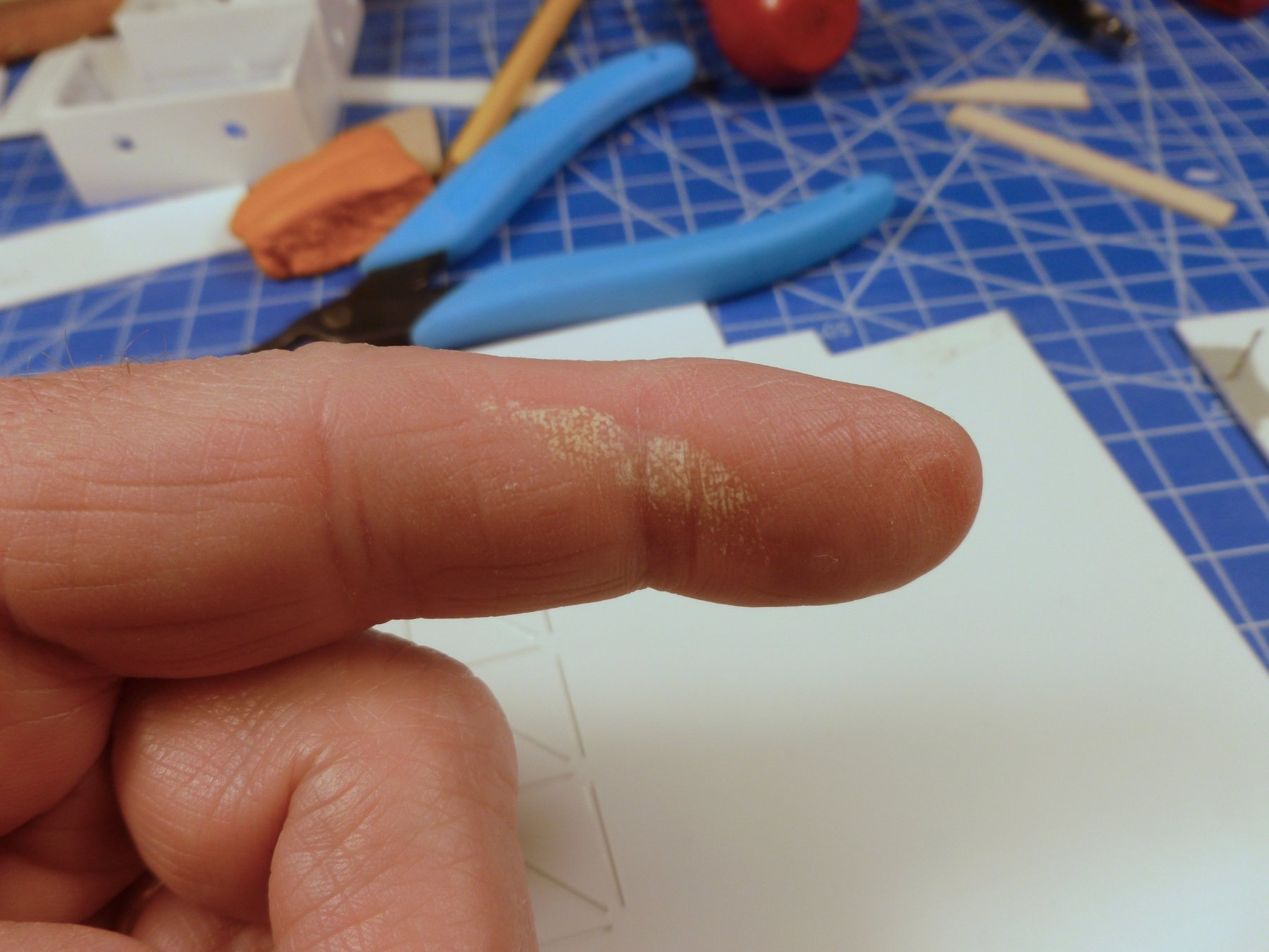
To those who gave likes, thank you and thanks for stopping by. Carl and Lou, thanks for your suggestions. I’ll try them going forward. You mentioned soldering - for something this small what do you use for solder/paste? I’ve done a lot of soldering, but mostly with lead solder on copper pipe and a few areas to join wires. What do you use for a tiny torch? Could CA be used in lieu of soldering? I made test 2 of the heat sink experiment, before seeing the comments above, and after putting a coat of paint on the plastic “deck” and the stanchion. The ragged railing holes are because the paint covered the holes as it was drying and I reamed them out a bit with wire. The tweezer nose pliers did act as a heat sink, resulting in a paint burnout where the pliers gripped the stanchion. There was also a little bubbling of the paint in the immediate area of the penetration. Collateral damage occurred when I touched the barrel of the iron rather than the handle. While painful it gave me a good idea of the amount of heat being generated in a very small area. The paint burnout at the pliers makes me believe I’ll need something well insulated if I try to hold a railing section while heat sinking it. I’m a bit concerned about pushing from the top rather than near the base since the stanchion is not round and bends in the narrow plane quite easily. I’m thinking the process might be: Build and subassemblies using a jig as suggested by Lou and Carl. Grip stanchion in the smallest area possible to minimize burnout Apply tip of iron close to base of stanchion to shorten the heat travel to the insertion point, but not so close the paint can’t be touched up without mucking up the deck Touch up paint at gripping and iron points Alternatively I could dispense with the pliers and use some insulated gloves but I’m uncertain whether I can manipulate such a small piece while wearing them.

- 446 replies
-
- 5
-
-
- zebulon b vance
- deans marine
- (and 3 more)
-
Just thinking, I'll have to test a painted stanchion and a painted deck. I'm guessing the iron tip will scorch the paint, but touch ups may be a tradeoff for not having to paint the entire assembly in place.
- 446 replies
-
- 1
-
-
- zebulon b vance
- deans marine
- (and 3 more)
-
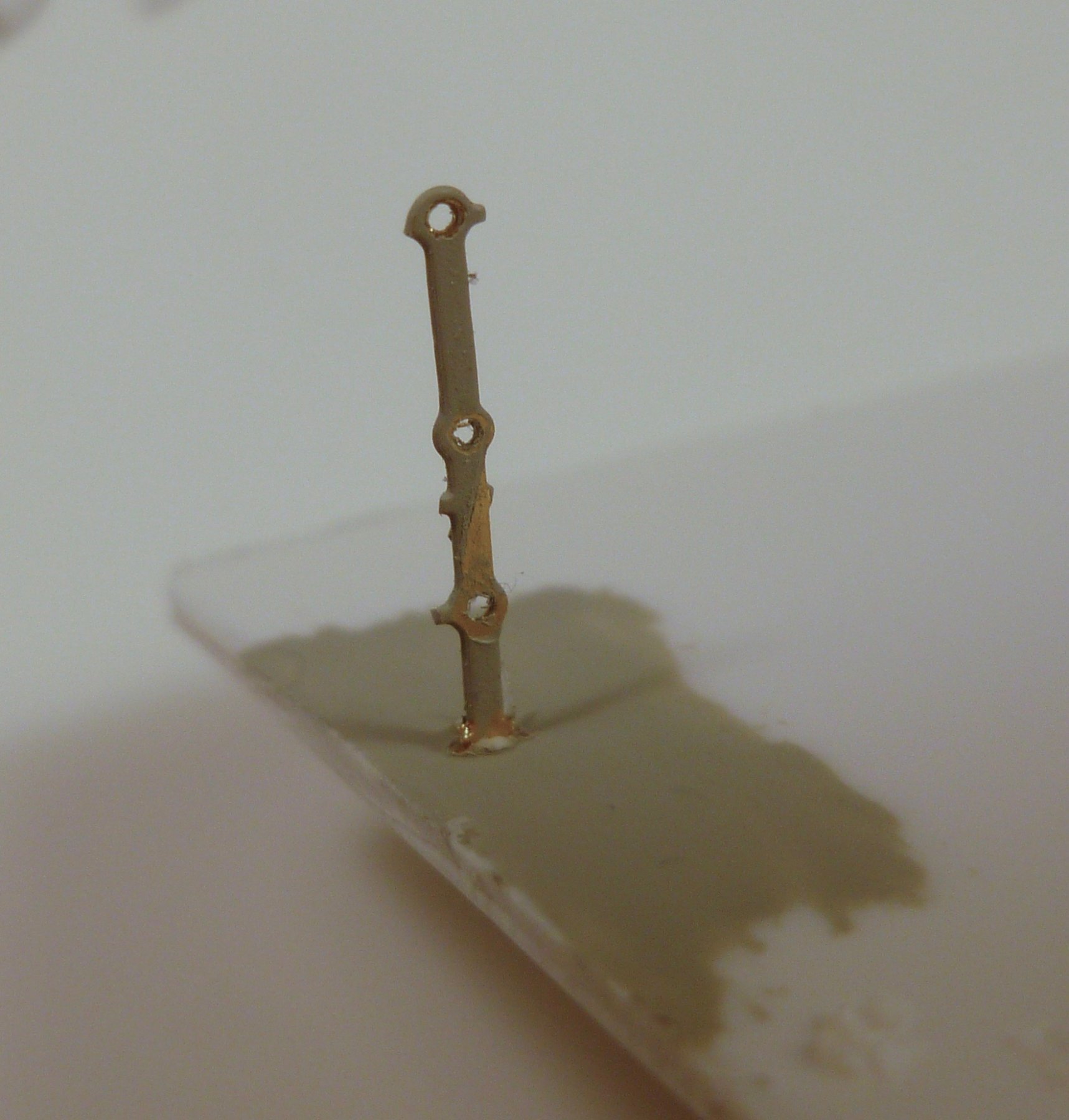
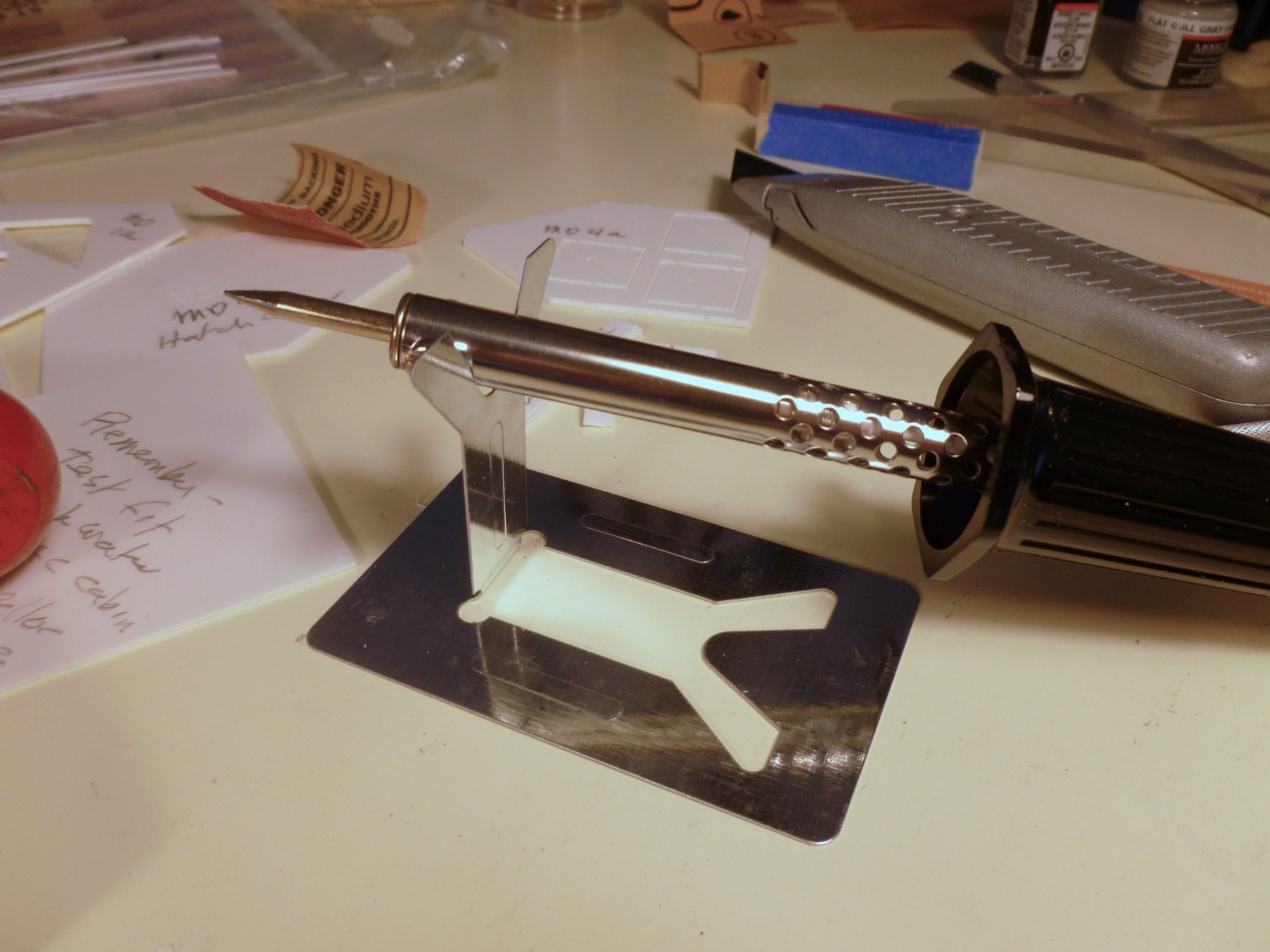
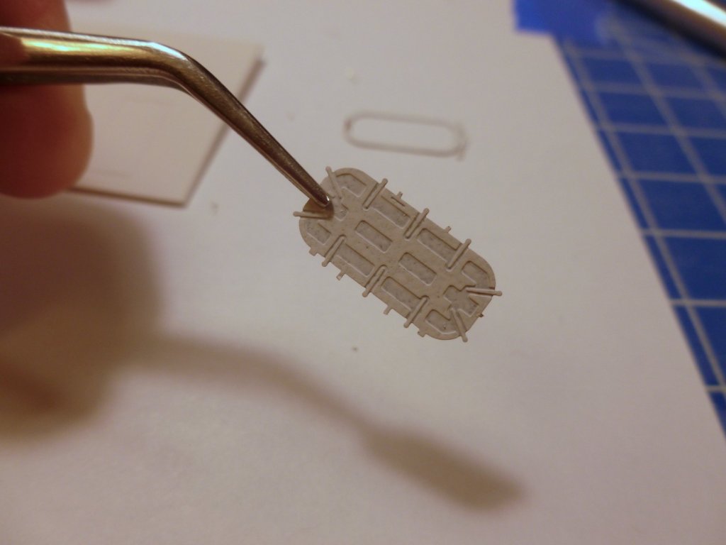
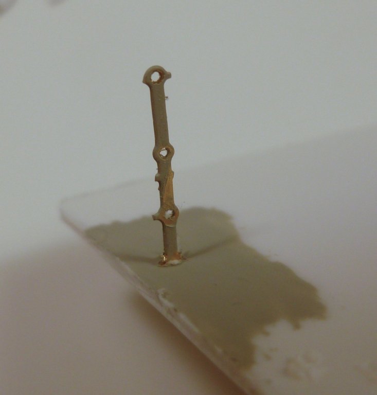
To those who gave likes, thank you and thanks for stopping by. Carl, thanks for the redirect. You’re welcome to take some credit for any good stuff. You’ve been with me from my maiden voyage with the Bowdoin. John Allen, I agree that some of the lesser known, but important parts of our history deserve more recognition. Schooner, I looked at Bluejacket’s Liberty ship for a possible kit bash to a war bride ship. I really liked the kit but with only one build behind me I felt I do not have the skill yet. mtaylor, thanks for your feedback. Since they are all watertight doors I'll need to figure out which openings would be likely to have portholes. Tom in NC, the Vance was originally constructed in North Carolina. The conversion to hospital ship was in Boston, and the quicky retrofit for war bride use was in Brooklyn. Steve The instructions recommend setting the railing stanchions using a “heat sink” method, wherein you heat up the stanchion by resting a soldering iron tip against it, while holding and pushing down on the stanchion with tweezers (it’s too hot to finger hold). Since there are 600 of them I figured anything is worth trying. I made a test with a stanchion snipped from the PE sheet, and found that after a few seconds the hot stanchion point melted the plastic just enough to slide down into it. As soon as the iron was removed the plastic hardened and made a nice stiff joint. The goober on the plastic is where I accidentally touched it with the hot iron tip. The photo below shows how the stanchion penetrated the plastic. The last photo is the 30W soldering iron. The pointed tip was just enough to heat the stanchion without melting it. Now I have to figure out how to make a jig so I can pre-assemble railing sections so I’m not trying to thread wire through the installed stanchions. Suggestions are welcomed.

- 446 replies
-
- 6
-
-
- zebulon b vance
- deans marine
- (and 3 more)
-
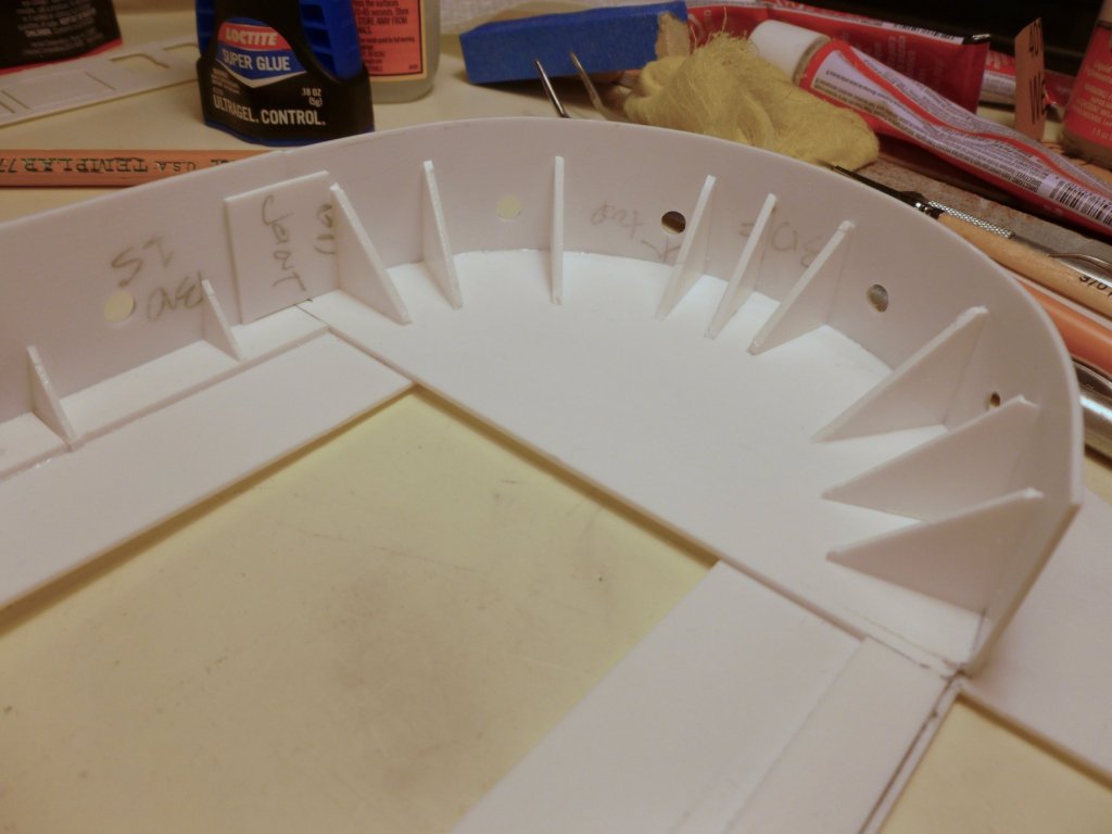
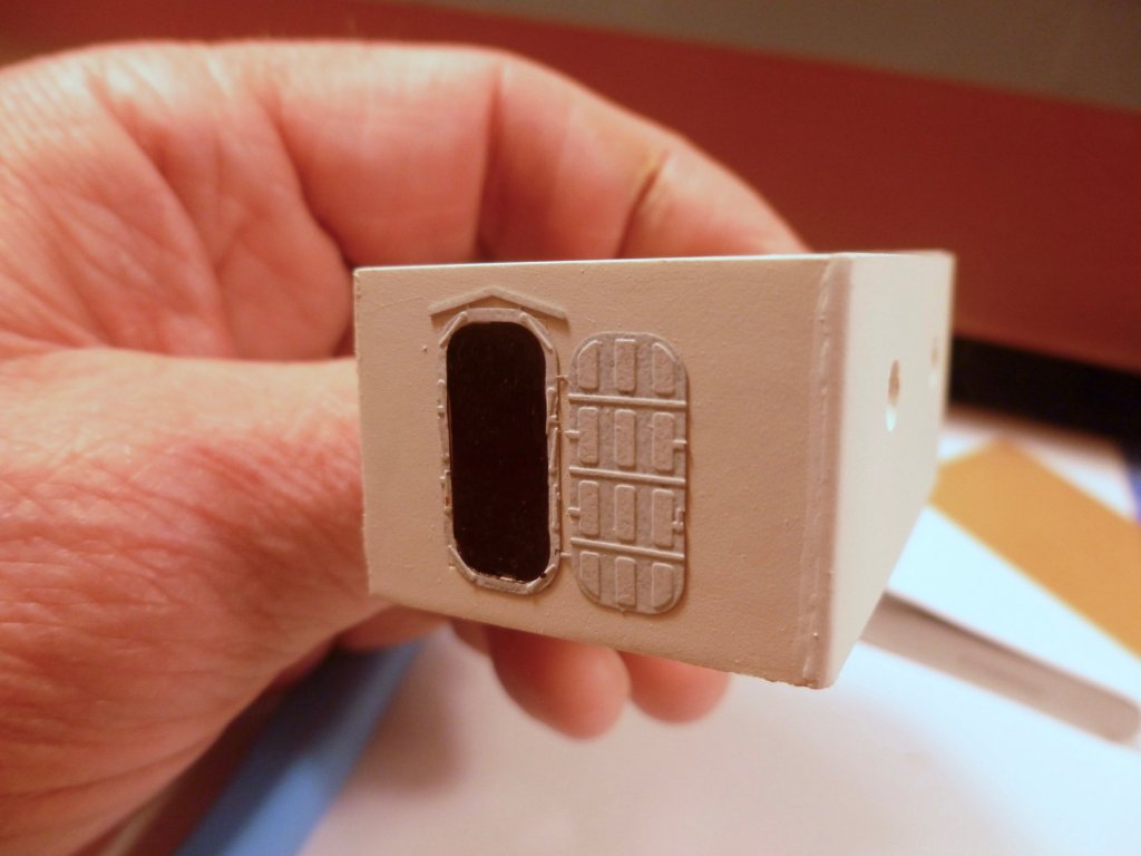
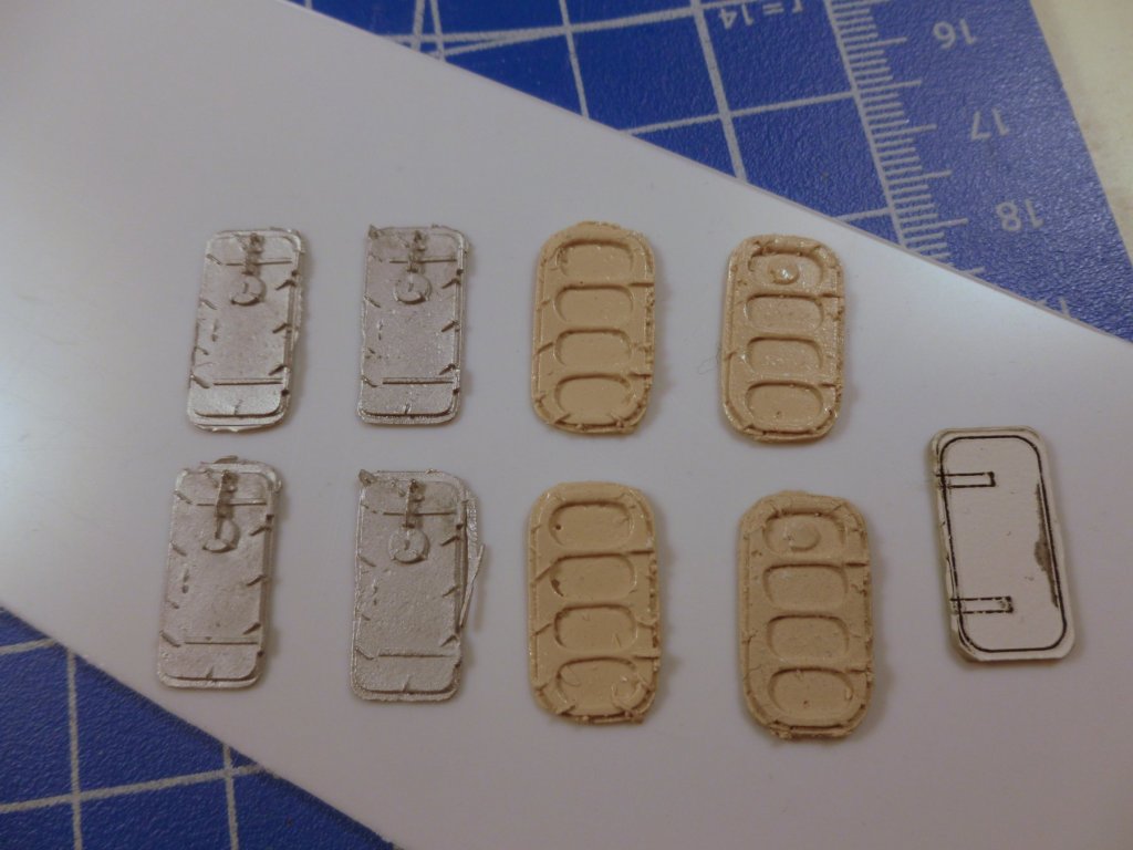
To those who gave likes, thank you and thanks for stopping by. Carl and Kevin, thanks for your support and encouragement. Steve Each door lobby, and all outside corners elsewhere calls for rounding off. I fashioned a sanding block with a curved recess. Sandpaper was anchored with the round file clamped in place while the spray glue dried. Photos below show in action and a slightly blurry result. While pondering how best to mask the promenade openings for painting them white on the exterior I had second thoughts about the inside face above the line of the bulwark. Since the promenade openings were added during the transition from Liberty ship to hospital it seems reasonable to assume the upper promenade area would have started out white rather than gray. Anyway, that’s my story and I’m sticking to it, so I masked to allow painting both the inside and outside promenade face. About 4 hours worth of taping and fiddling and another half hour to paper and tape the hull interior which doesn’t show in the pic. Can anyone fill me in on the two different door styles? The white door, which you have seen before is shown for cabin doors. The metal door is listed as watertight, and the molded yellow door just says door. The instructions and build photos are a little vague. If there is a rhyme or reason as to the use for each type (other than the white doors) please chime in. And by the way, do I have the doors right side up? I'm assuming the round covers are over portholes.


- 446 replies
-
- 6
-
-
- zebulon b vance
- deans marine
- (and 3 more)
-
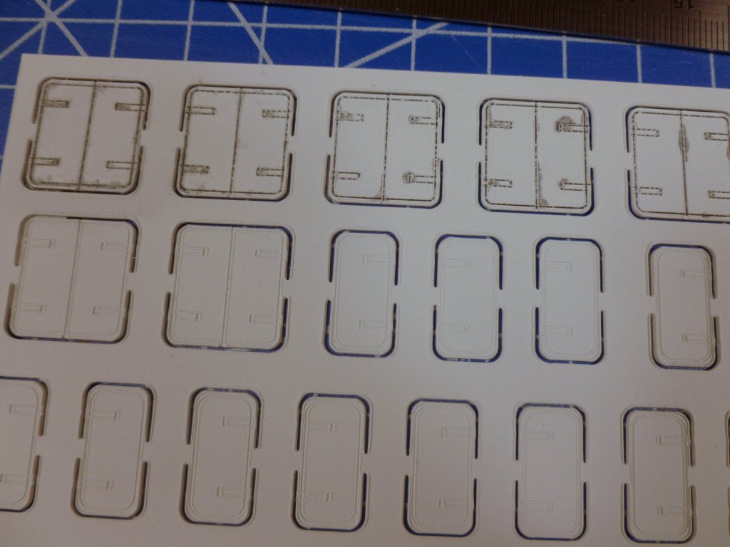
To those who gave likes, thank you and thanks for stopping by. Steve Fall leaf cleanup, travel, the replication required for each step and a maddening do-over took their toll on visible progress the past few weeks. To keep the door lobby sides perpendicular while the glue takes an initial set I used some scrap wood as mini-clamps finger-pressed together. I took several breaks during the cabin wall installation to work on the doors. After painting and highlighting the door faces I removed them from the carrier sheet, secured them to tape strips and highlighted the edges with light gray, followed by a coat of Dullcote. The boat deck sits on top of the main deck cabin walls. Before painting the cabin walls and main deck i thought I should check the fit of the two boat deck sheets so I could sand the wall tops and the boat deck sides if needed. Then disaster struck. When I placed the aft boat deck sheet there was a 5 mm gap on both sides between the deck edge and the promenade walls, which extended several inches (sorry for mixing metric and Imperial) on each side. Was the gap due to a poorly lasered deck, a mismatch between the main and boat deck sheets, a construction problem or something else? In an effort to pull the hull sides closer to the boat deck I excised another bit out of the the rudder servo support beams, pulled the sides together and held them in place with tape while I sistered new wood strips alongside each beam. Unfortunately the closure was excessive and put strain on the hull, which in turn gradually stretched the tape and broke the bond between one servo support perimeter beam and the hull. I had to reduce the compression of the sides and reposition the sisters to allow the perimeter beam to be reattached to the hull. Compounding the misery I thought I should narrow the aft cross hull support beam so I trimmed 10 mm from one end, pulled the sides together and re-glued it. Unfortunately I removed the tape too soon and when I came into the shop the next day I discovered that the glue, which looked to be hardened, had stretched enough to return the cross beam to its original position. While it felt solid I decided to add a new cross beam adjacent to it. With the hull sides in the position that felt most comfortable for them I turned my attention back to the main and boat decks. The narrower hull necessitated sanding both sides of the main deck. When I did that I discovered that the boat deck gap was not only gone, but the boat deck slightly overlapped the promenade walls in a few spots. More sanding created a good fit. The lesson learned (again) is that a millimeter here and a fraction of an inch there can add up, and if you are not careful you may make adjustments to something that didn’t need adjusting in the first place. The boat deck is finally fitted. Now it can be removed so I can continue work on the main deck. An aft cabin will be constructed on the main deck under the boat deck overhang. The main deck forward wall is test fitted, thankfully without incident. The layout lines are for the air conditioning room.


- 446 replies
-
- 7
-
-
- zebulon b vance
- deans marine
- (and 3 more)
-
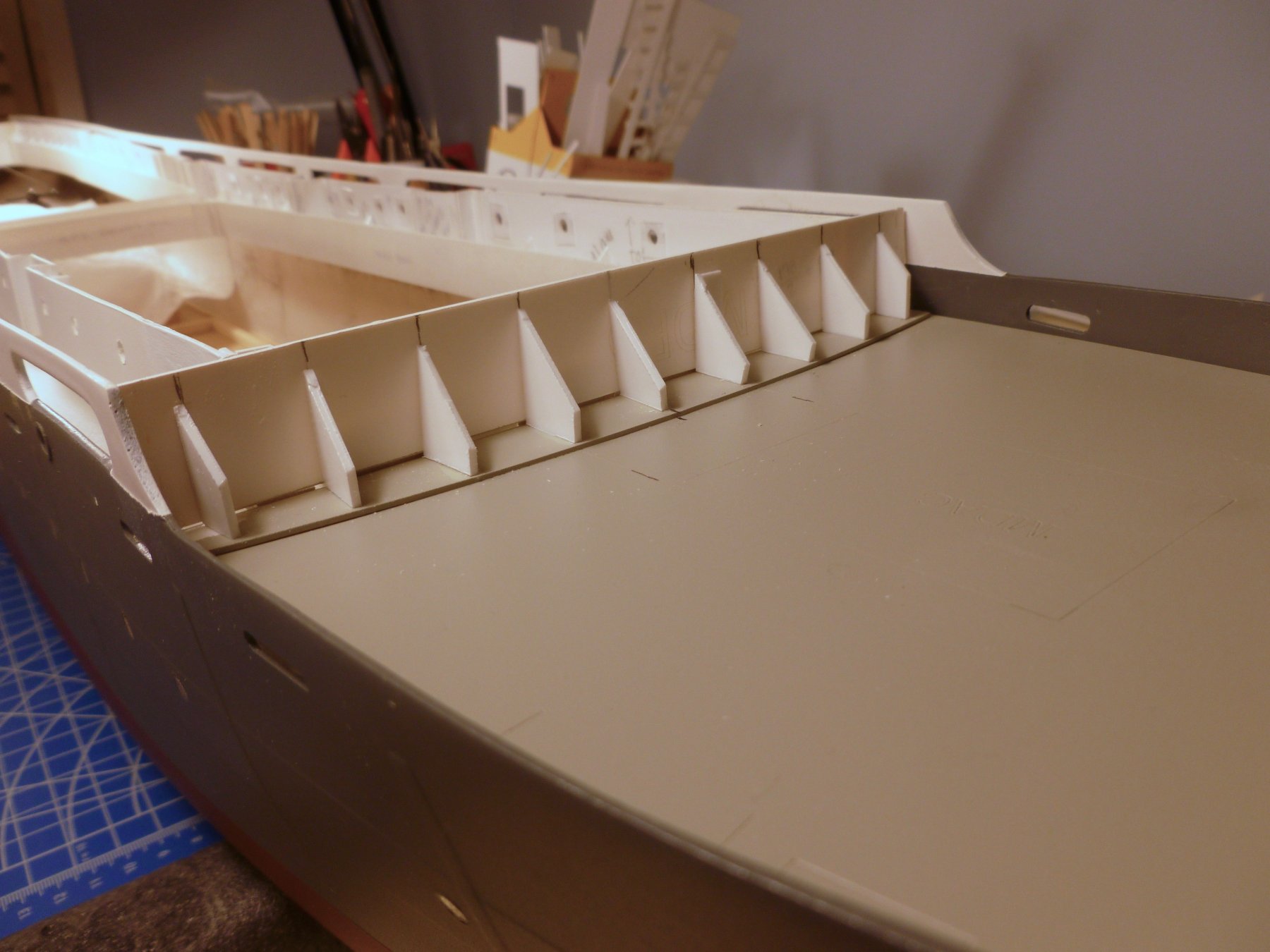
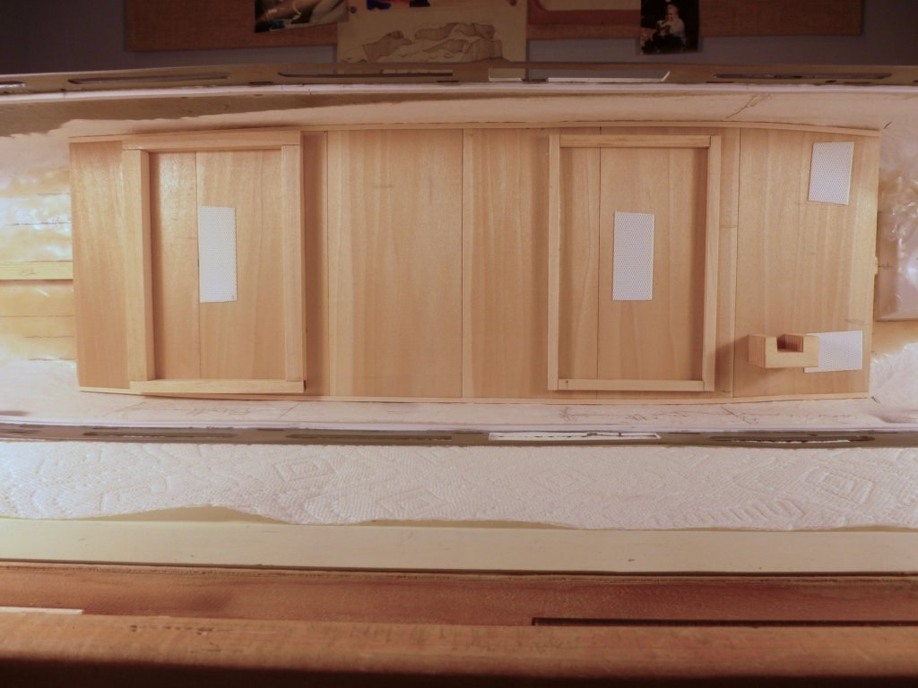
To those who gave likes, thank you and thanks for stopping by. Carl, I hope I'll show something novel from time to time. Steve After much thinking and reading I started on the main deck starboard cabin walls. The instructions call for placing, but not gluing the main deck, and ensuring the sheer is maintained. Tape pulls the hull sides together and clothespins press the deck to the perimeter support beam. Each cabin strip is then fitted to the sheer. The pins and tape were removed for the photos. The bases of the wall strips are anchored with the flat support strips placed previously. Small triangles provide additional stiffness. The view forward shows one of the door lobbies. The laser layout line in the deck generally locates the lobbies, but is not entirely accurate, relative to the cabin wall strip length Each door lobby consists of two side return walls and one wall across the back with laser lines for door locations; and is backed up at each corner with two support strips. If you look closely you can see how I had to adjust the right lobby return wall placement since the layout line left the cabin wall strip a millimeter short. Fortunately the door lobby back walls are sufficiently wide to allow trimming to fit. In between thinking and fitting the cabin walls I painted a few doors to match the hull color, for later positioning over the location tabs within the hull sides port and starboard.

- 446 replies
-
- 7
-
-
- zebulon b vance
- deans marine
- (and 3 more)
-
Carl, thanks for your quick input. The superstructure on the Vance was white and the doors shown above had a prime and topcoat of flat before I started experimenting with highlighting the cut lines and hinges, with flat black mixed with thinner. I plan to Dullcote the lot after I'm finished with them. A couple of doors need to be painted dark gray since they are located within the body of the hull. Perhaps I'll try something lighter there for a highlight. Thanks again for your ongoing interest. I really appreciate it. Steve
- 446 replies
-
- 5
-
-
- zebulon b vance
- deans marine
- (and 3 more)
-
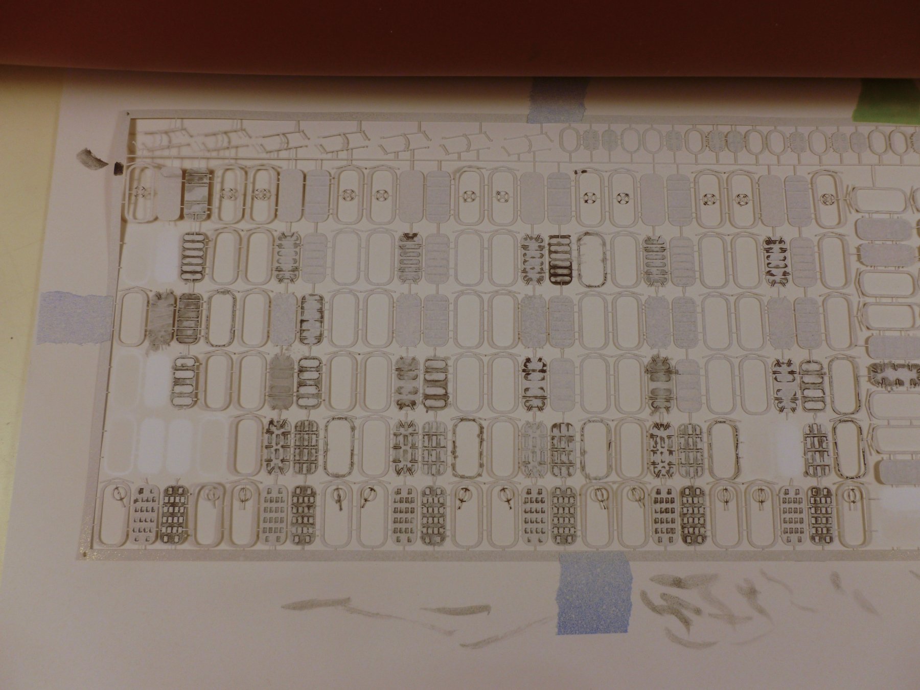
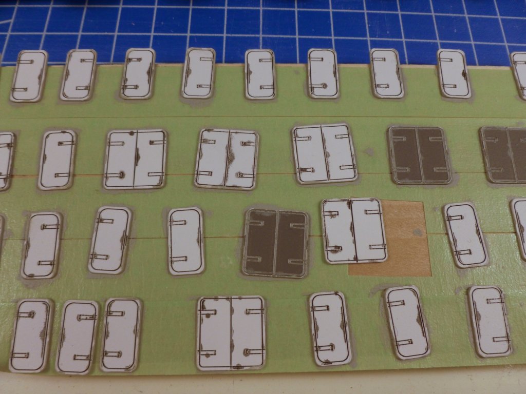
To those who gave likes, thank you and thanks for stopping by. Steve The main deck cabin walls are located with a layout line inscribed on the deck. The walls are stiffened at the base with a strip set 1 mm back from the layout line so step 1 is to add all the base lines. The base strip is installed while the deck is set in place to maintain the sheer, but the deck is not glued until later. A view aft of the layout lines. The instructions call for installing all main deck cabin walls permanently while the deck is set in place, then removing the deck and walls as a unit for painting, before gluing the deck in permanently. This seems to make rounding off all the wall corners a problem, and I’m concerned about getting a clean paint line between deck and walls. I would like to paint the walls off the ship, but they are not boxes, just strips of walls with sheer, and insets for door lobbies. If anyone has a suggestion about sequencing please chime in. In addition to the base plate the walls are stiffened with support triangles and corner stiffeners. Shown are squares of triangle pairs as cut from the carrier sheet, before final separation and sanding. The forward main deck has a support wall for the boat deck above, installed behind the primary forward wall which is two decks high. As laser cut the support wall width is a little short of the full deck width but I found that if I include the ends of the carrier sheet it makes the width perfect. Shown is the support wall with filler drying, and the two story primary wall resting against the sanding block. The primary wall will be installed against a curved base plate and the forward end of the boat deck. Since doors are installed with the wall strips I experimented with a black wash highlight. Test 1 is top left, and skill building goes to the right. I just touched a very small brush to the incised lines and the wash wicked its way around. Is that how highlighting works? I’m not sure if this is how they are supposed to look but it seems to give a reasonable impression of a door with wear and corrosion.


- 446 replies
-
- 8
-
-
- zebulon b vance
- deans marine
- (and 3 more)
-
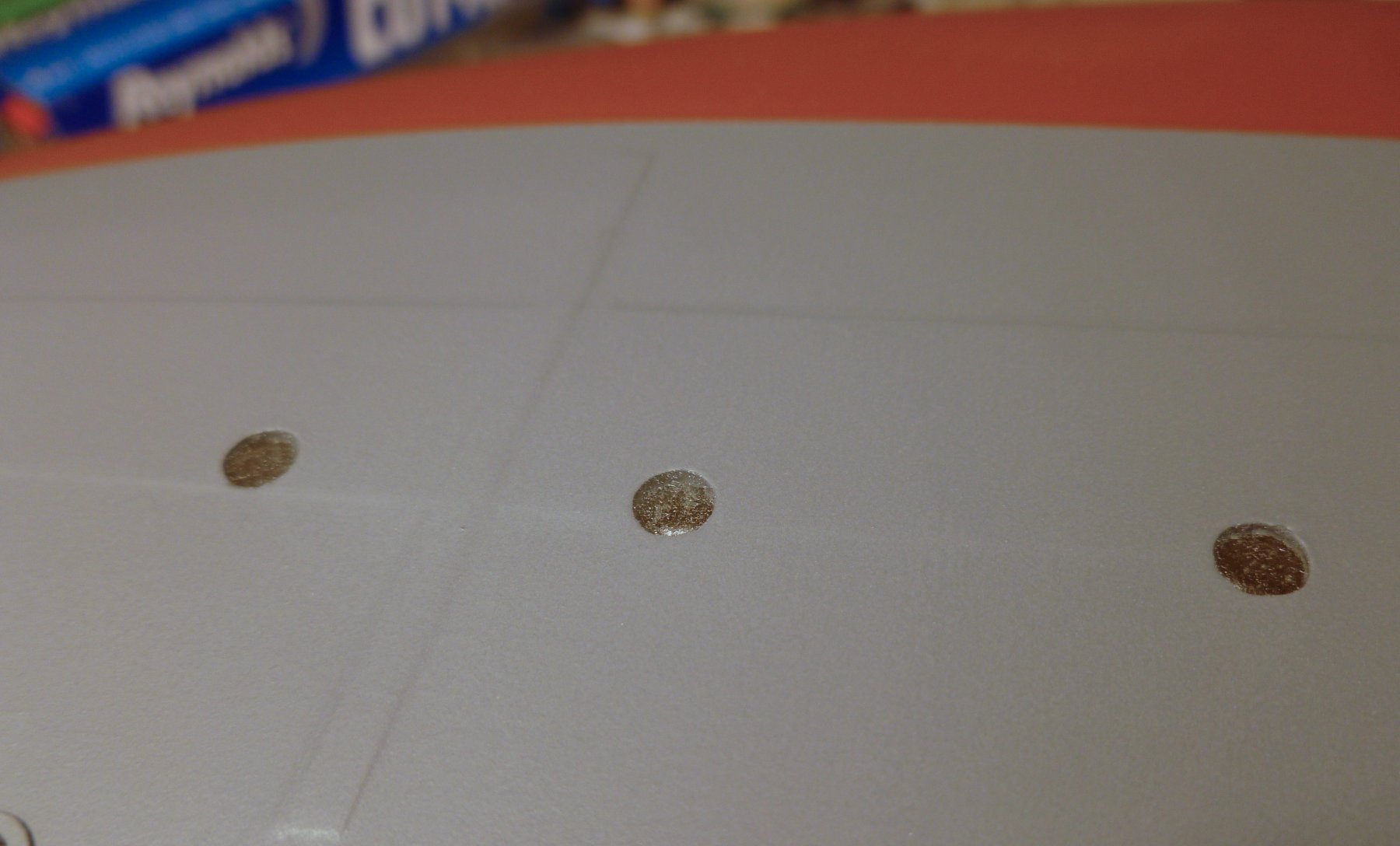
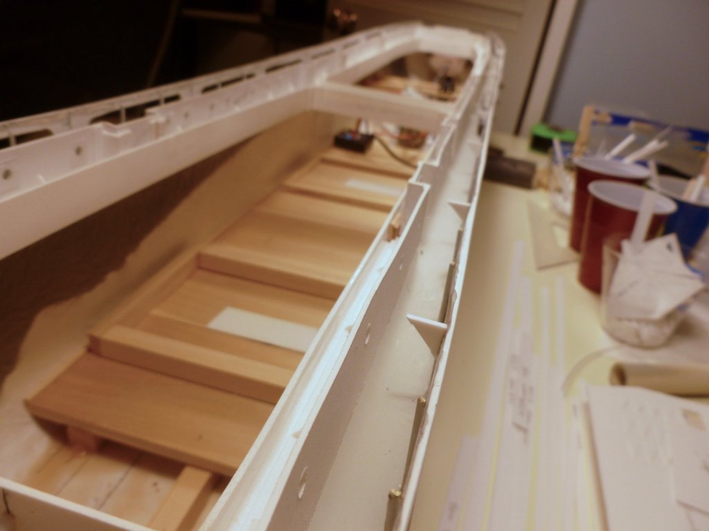
To those who gave likes, thank you and thanks for stopping by. Kevin, I’m glad the waterline tip I learned about was helpful to you. Steve Time to start buttoning things up below the main deck. The electronics deck is complete except for placement of the power and control bits. The heavier crib on the left is for ballast (the spare battery). The deck was tarted up with a a bit of trim at either side and coat of wipe on poly. The white strips are Velcro to better secure the components. As shown in the earlier pics I sanded and fitted the main deck, then set the pieces aside until later. After installing the servo cross beams I reset the main deck, only to discover that a slight misalignment when installing the servo cross beams resulted in them pushing the hull sides out just enough that the deck wouldn’t sit on the perimeter beams. The photo shows where I Dremel-excised a piece from each beam, pushed them together a bit and added two scabs. The good news is when I temporarily connected the power components, the RC transmitter operated the rudder in fine fashion. The transmitter has two trim controls that allowed fine tuning of the rudder arc and center neutral point. The instructions suggest using two part clear epoxy to fill the hull portholes, after taping over the exterior of each one. Remember, this ship will be in the water. It worked, sort of. The epoxy seems to have taken a bit of texture from the sticky side of the tape, but it’s not altogether unpleasant so I’ll leave it. The lesson learned was to use much care when placing the epoxy into the porthole. On the first few I dabbed a blob in the hole then dragged across it with a craft stick that looks like a tongue depressor, thinking it would drive the epoxy into the hole. When I removed the tape each porthole had a nice broken air bubble at the exposed edge of the hole, which I had to fill with more epoxy and a toothpick. Doing some reading I found a comment about filling holes in fiberglass with epoxy, which said to never drag an epoxy filled putty knife over the hole since it would guarantee an air bubble trapped at the bottom. The recommendation was to pre-wet the sides of the hole with epoxy, then fill the hole from the bottom up with a syringe. Since the portholes are not very deep I decided to use a disposable paintbrush to introduce the epoxy into the hole, coating the sides and bottom and gradually working my way up. It worked quite well and resulted in a full face on the finished epoxy. By using the magnifier headset I was able to see any air bubbles lurking at the bottom, then prod at them with the brush tip to break them up and vent them to the surface before the epoxy set up. The main deck is 1.5 mm and needs some stiffeners around the large hatches. Since the deck has sheer it needs to be in place and held down temporarily while the first stiffener strips are glued around the inside edge of each hatch. Once the strips are installed they must be reinforced from the underside, and the inside corners receive reinforcing too, since there is not much glue surface on the edge of the deck or at the corners of the stiffeners. While the deck was upside down a piece of PVC plumbing pipe was placed at the midpoint cross beam to help maintain the sheer curve.

- 446 replies
-
- 9
-
-
- zebulon b vance
- deans marine
- (and 3 more)
-
Andrew, thanks so much for the shout-out on my Bowdoin. I thoroughly enjoyed it as my first wooden ship build and I'm sure you will enjoy yours. I ran into the same problem with the subdeck being slightly short at the bow but I thought it was due to poor positioning on my part. Later in the build I fit a small piece in the gap. Regarding planking, the instructions say to fit the first four planks (from the sheer down) on each side without spiling, but this created issues later with trying to fit the remaining planks, especially at the stern. Toward the bow I needed a couple of drop planks each side and even then it was tight. Maine Maritime Academy has photos online of the Bowdoin restoration from about 2014(?) that were useful to understand mast, deck and bulwark details. They also have a series of photo logs of student cruises which were good for understanding the deck layout and capstan details. Rubber bands were a godsend for me too, along with metal binder clips customized as I saw in other builds to hold planks in place. I also used wood spring clothes pins sawed off to give a square end for tighter work. The compound plank bending was helped by soaking planks in boiling water for an hour, using a length of plastic pipe capped at one end and standing vertical. The clothes pins also helped to keep the planks from rising out of the pipe while they soaked. Thanks again and best wishes on your build. I'm sure you'll beat the 550 hours it took me. Steve
-
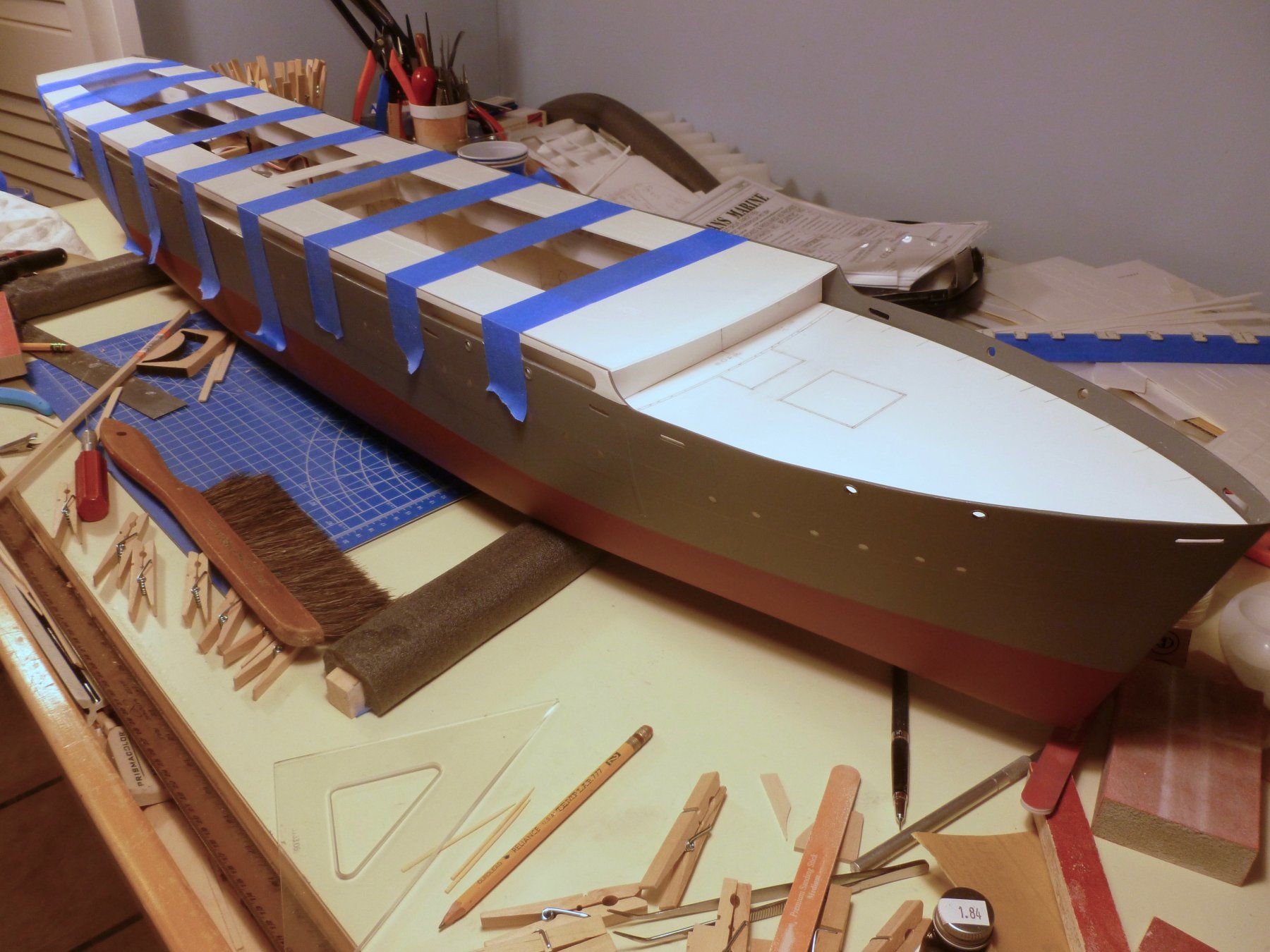
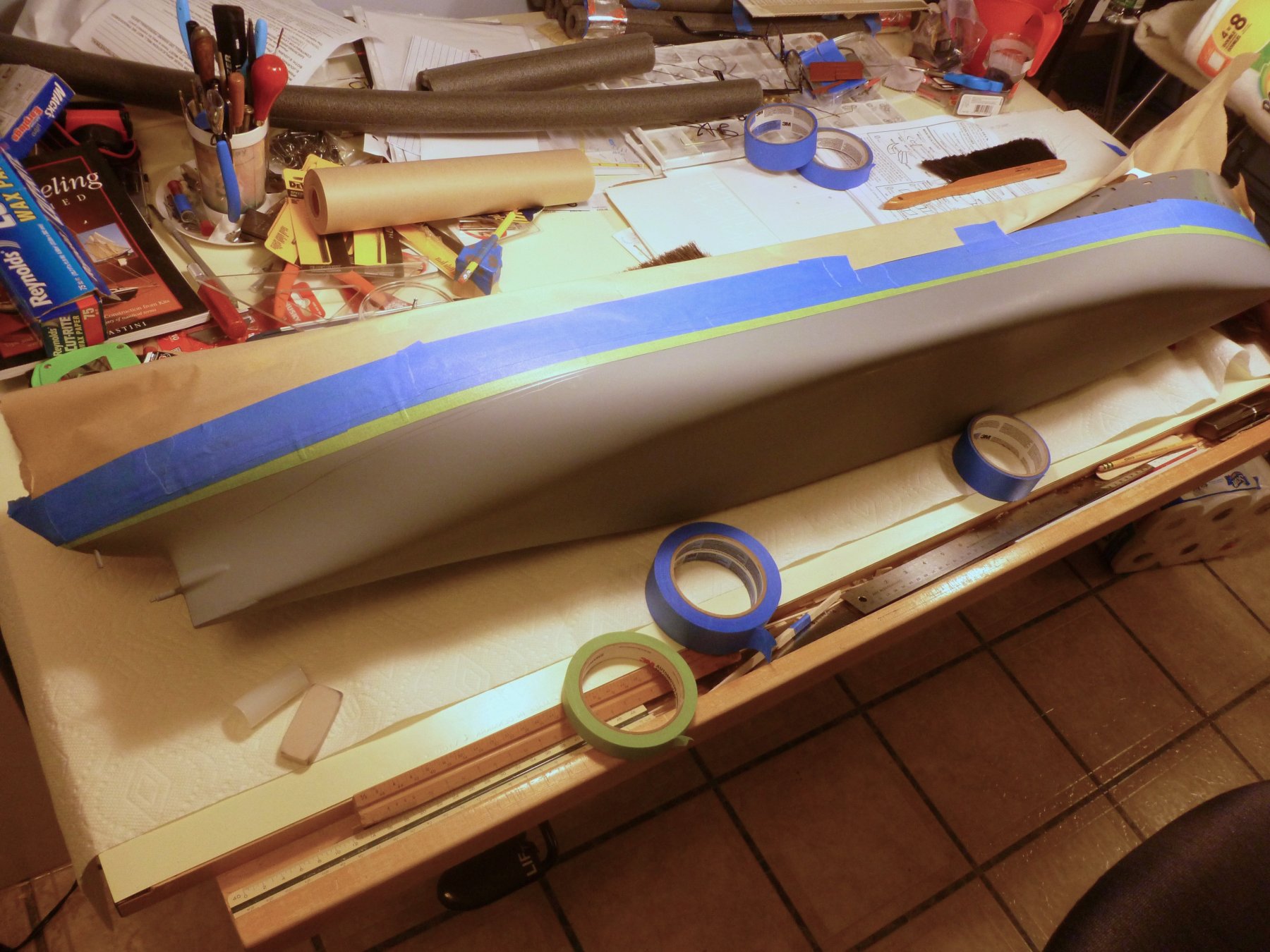
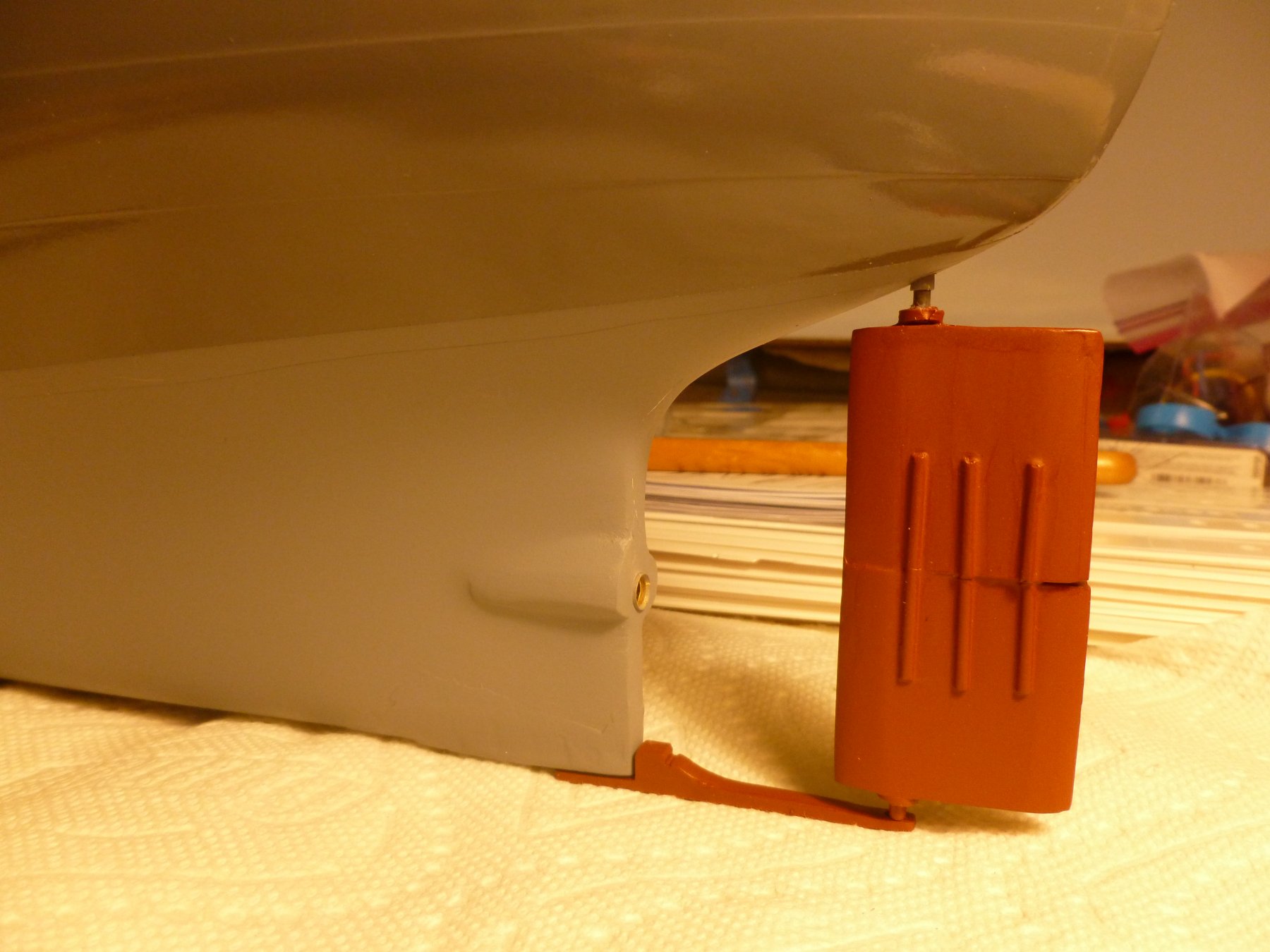
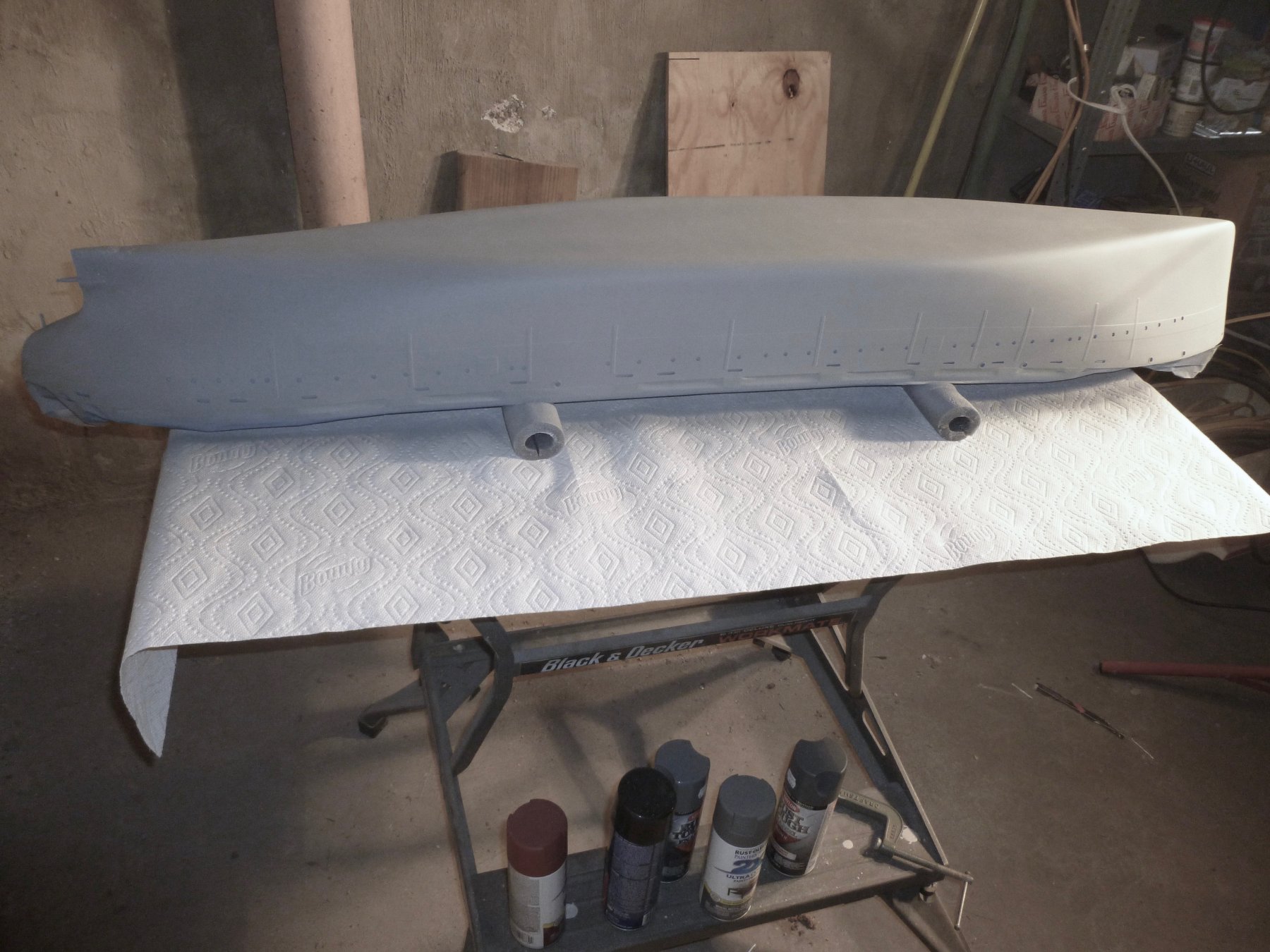
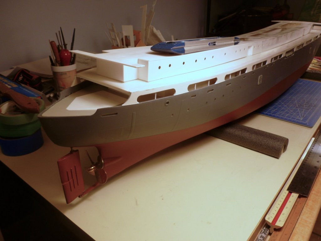
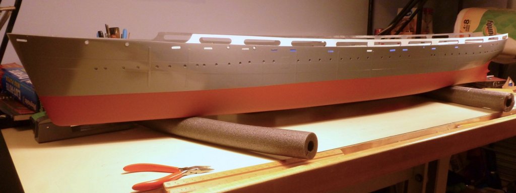
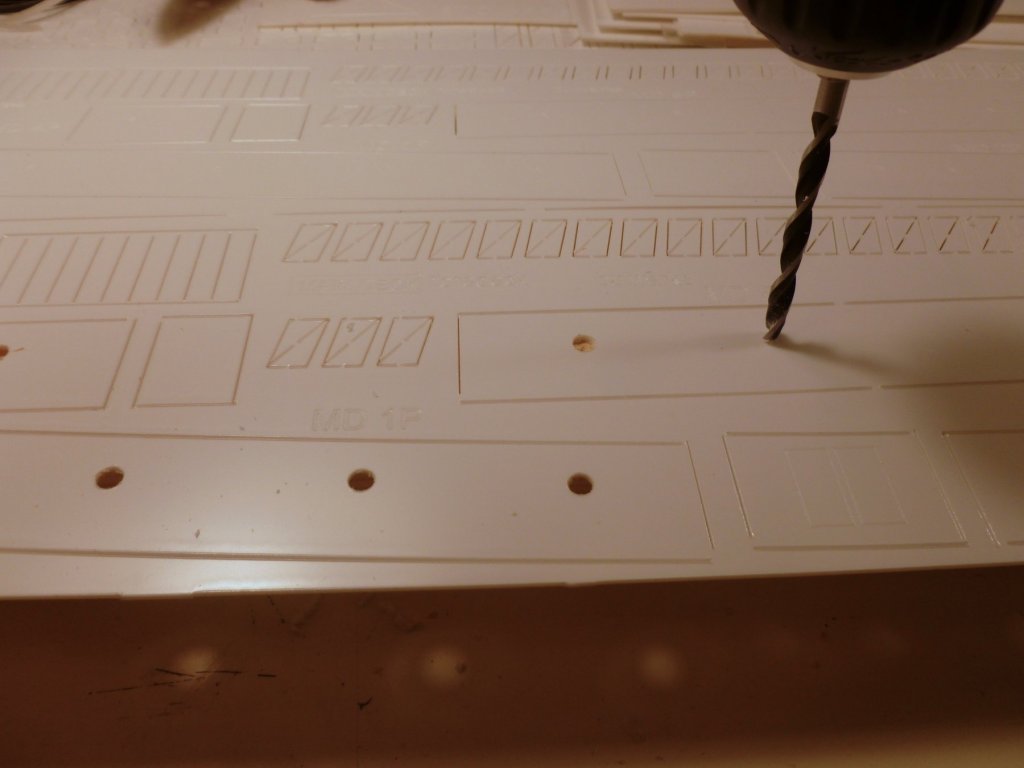
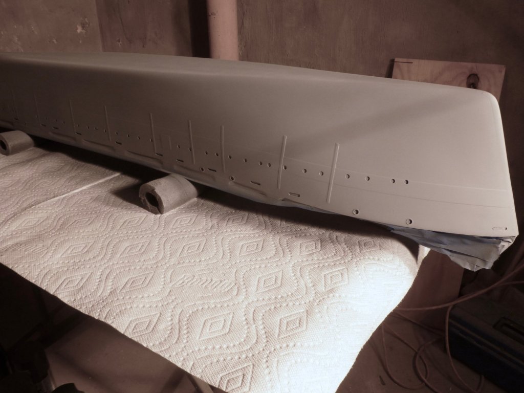
To those who gave likes, thank you and thanks for stopping by. Carl, perhaps the Vance is more interested in knowing where it has been than where it is going😄 Thanks again for your support. Steve Much hull priming and painting this week with infill work such as pattern placement for the base on a piece of oak, and drilling main deck cabin portholes. The new rudder arm arrived from England and was immediately test fit - what a difference in clamping power. The rudder and rudder support were temporarily placed. Once the upper hull was painted (except for the promenade exterior) the masking had to be reversed for painting the lower hull. A great tip to ensure a sharp waterline came from Mr. Bluejacket (Nic) in the company newsletter. The recommendation is to place and burnish the waterline tape and masking, then hit the waterline tape with Dullcote prior to spraying the finish color. The Dullcote blocks the color coat from bleeding under the tape. It worked perfectly all around the ship - about nine feet worth of very sharp waterline. Thanks Mr. Bluejacket! See below for the finish, prior to painting the promenade exterior, paint flattening with paper towels, and flat clear coating. The hull is just about ready for the main deck.

- 446 replies
-
- 13
-
-
- zebulon b vance
- deans marine
- (and 3 more)
-
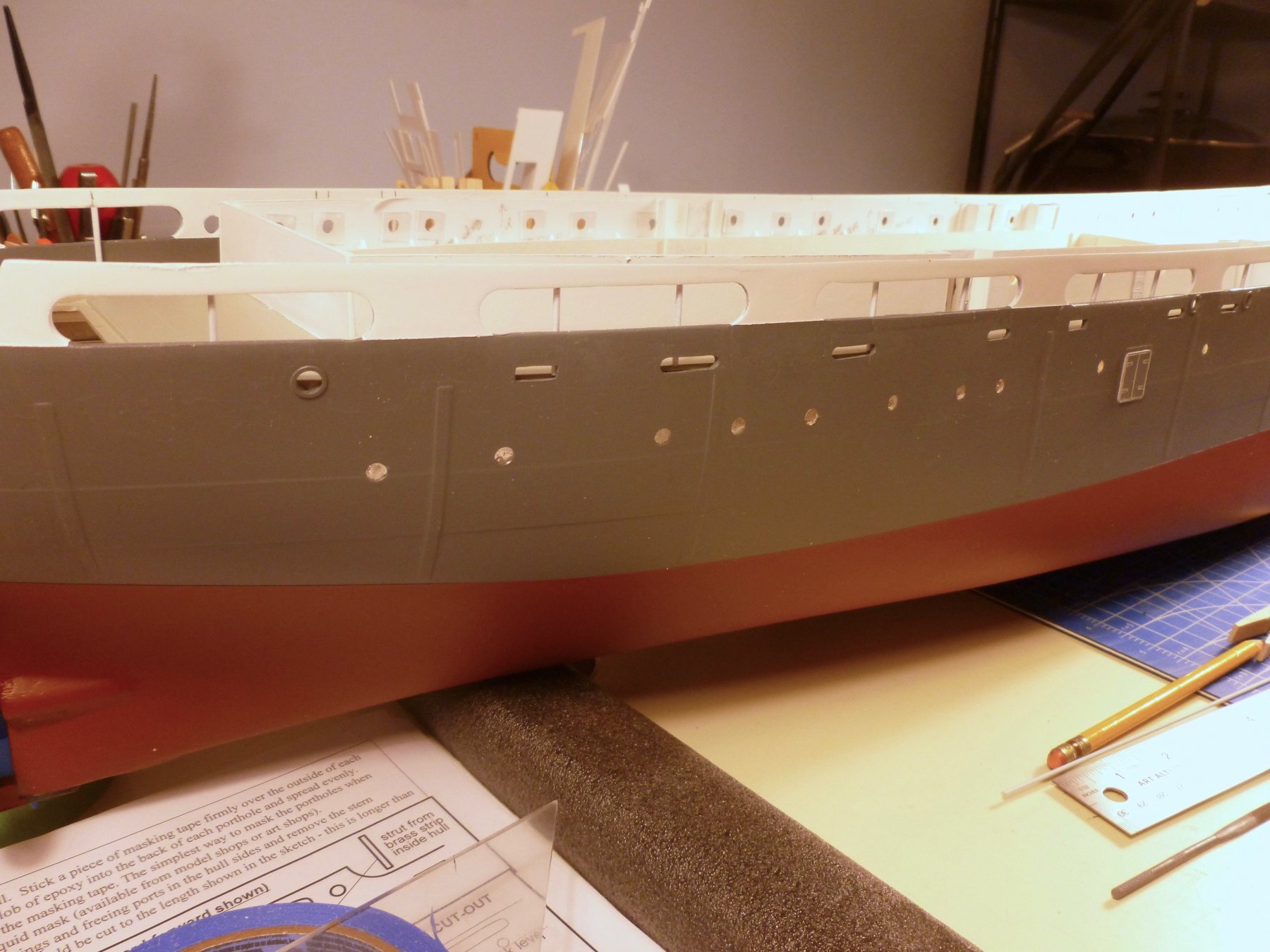
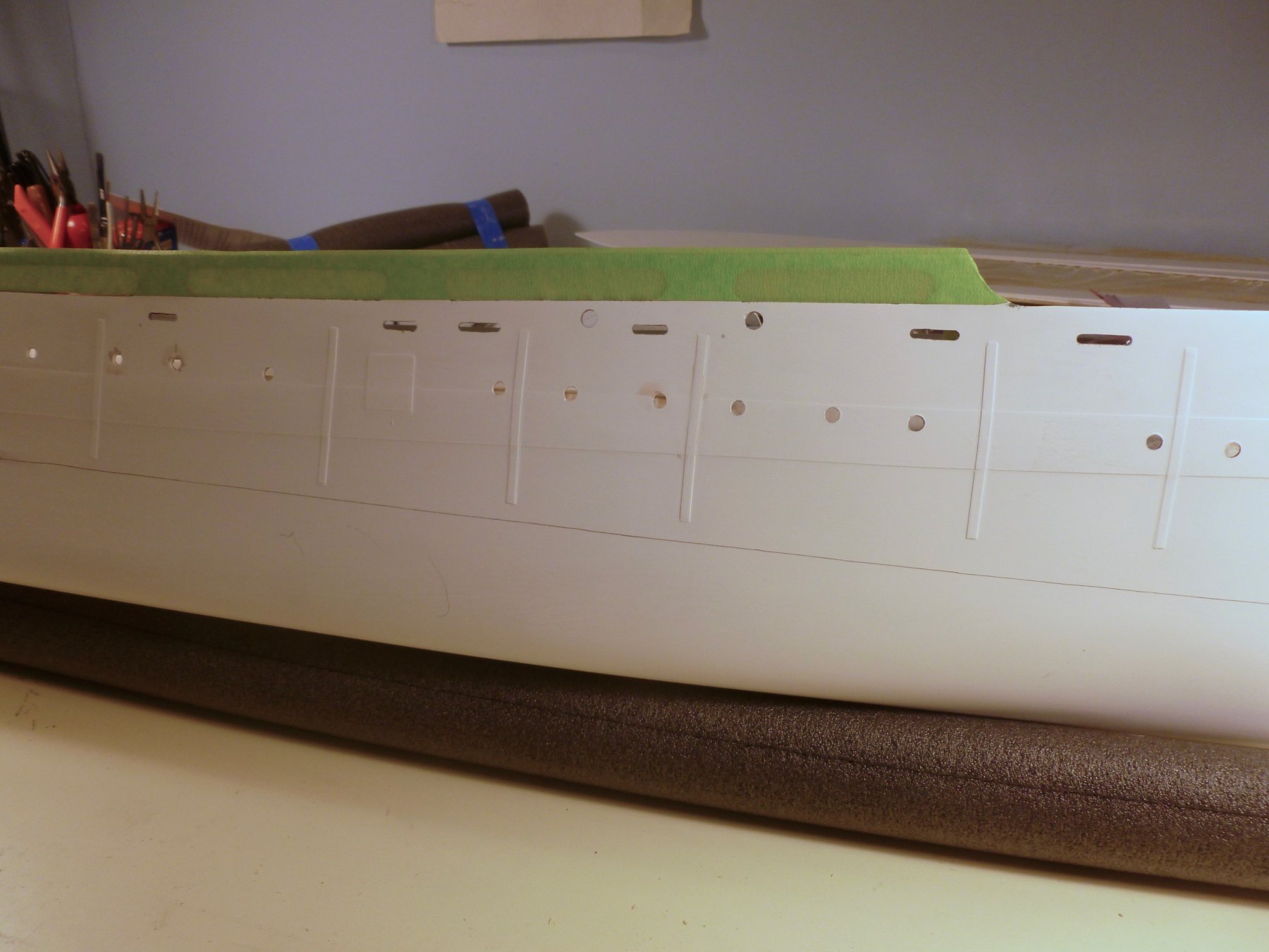
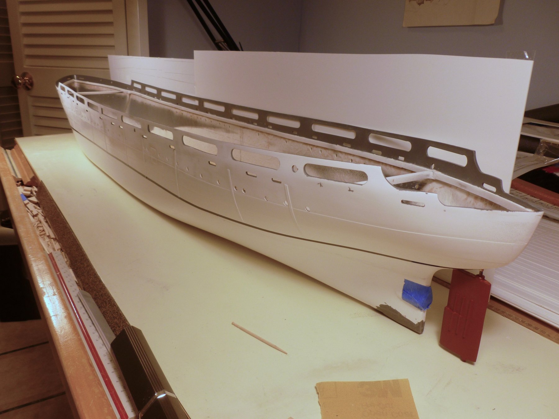
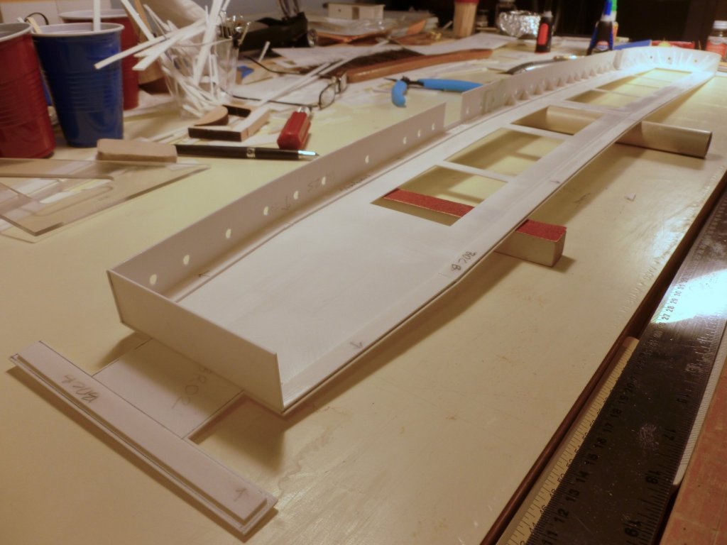
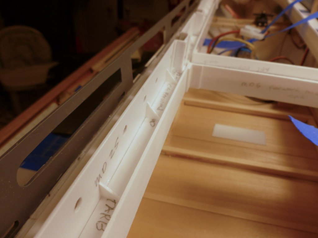
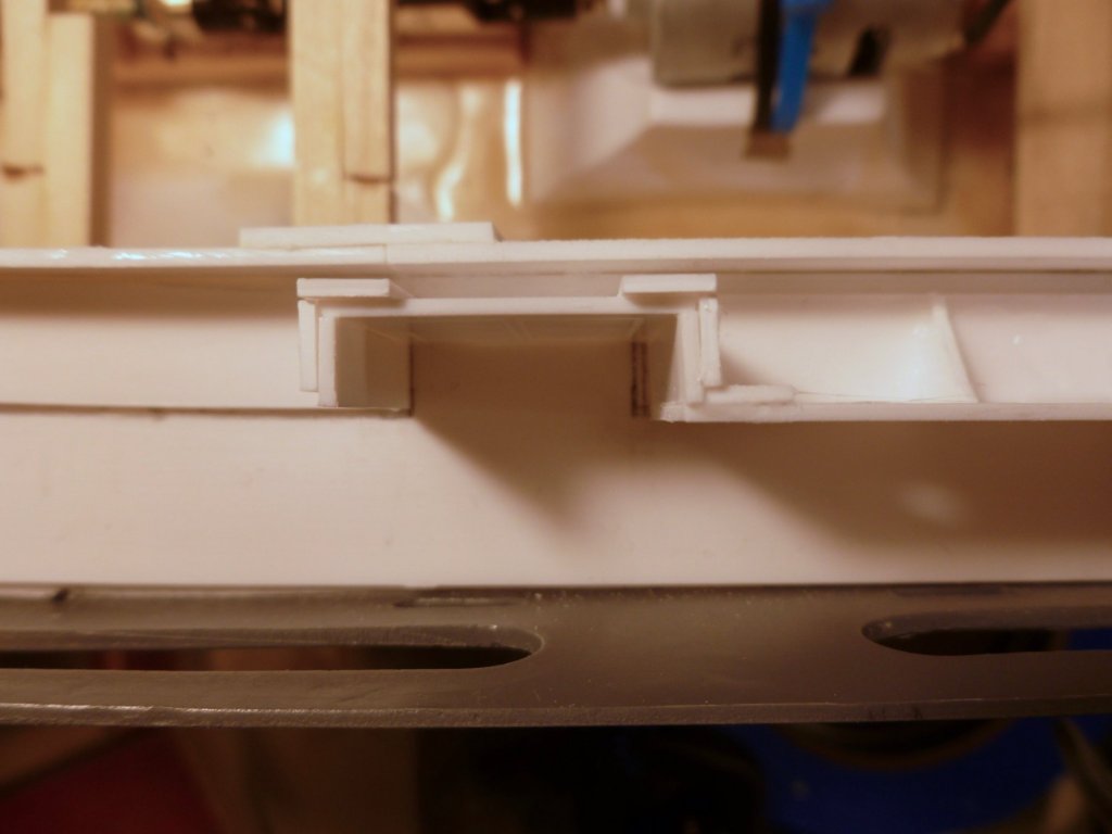
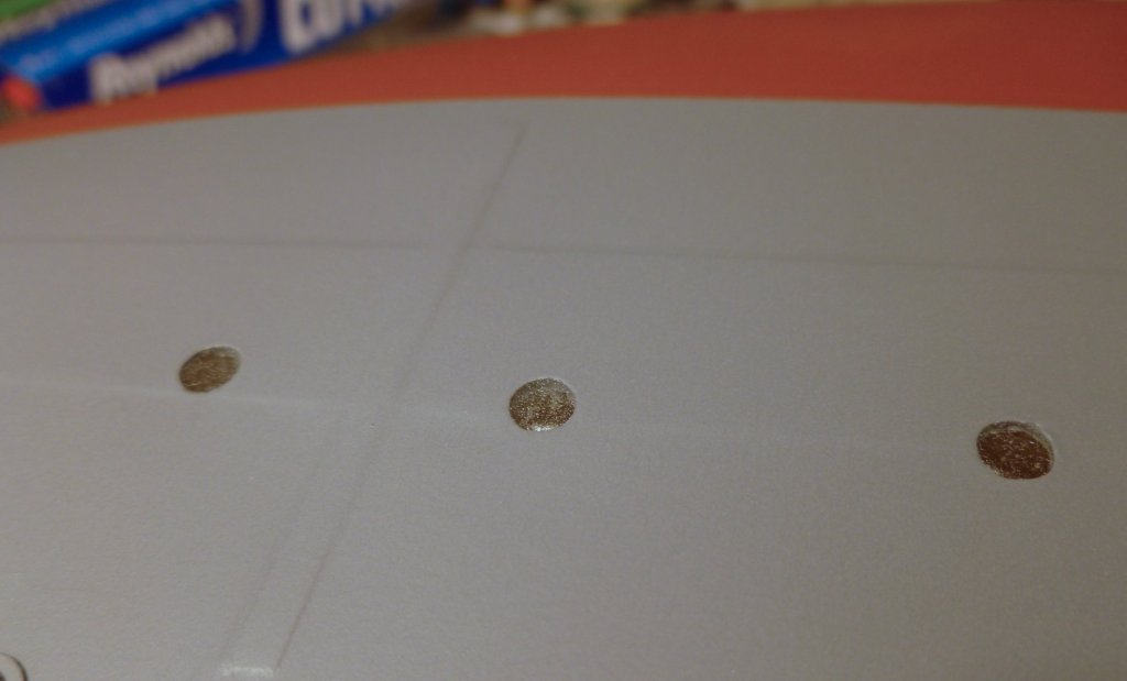
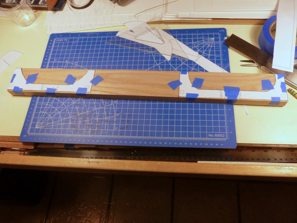
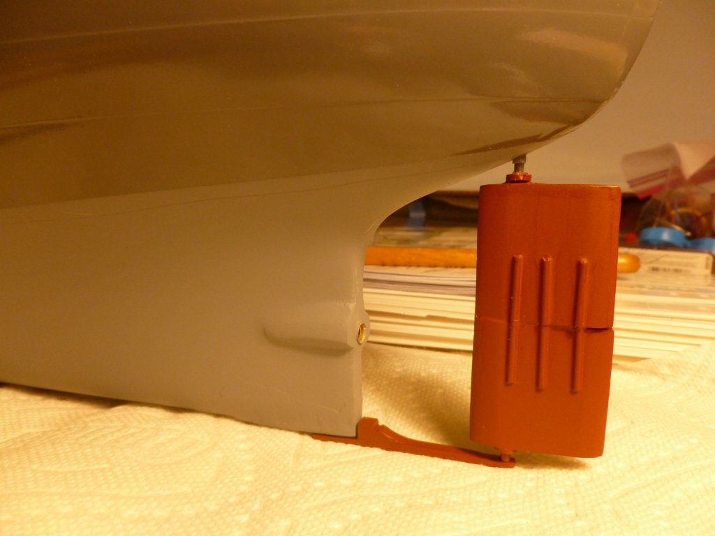
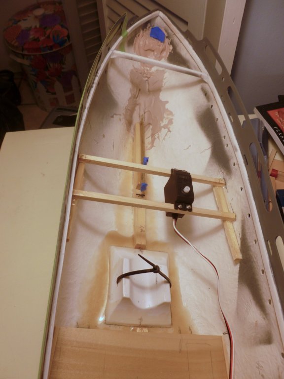
To those who gave likes, thank you and thanks for stopping by. Steve After priming, painting and flat clear coating the bulwark/promenade interior, I experimented with the waterline placement which is described as 57 mm high with a slight turn up at the stern to accommodate the rudder. The tape is temporary and the line will need to be redrawn after priming and upper hull painting. And yes, I know the rudder is backwards in the photo. What I don’t know is what possessed me to set it like that. Fortunately it’s not the permanent install. The servo support is interesting. After determining the placement a cross beam is cut to fit. To get the cross beam width I used two shorter strips of wood, slid them to fit the width and locked them together with a bit of tape. The cross beam was cut to the length of the taped strips. After the ends of the cross beam, and one end of each side beam were drilled, pieces of brass wire were installed which allowed the side beams to swing as needed to engage the port and starboard hull. The side beams were taped in their final positions, tacked with medium CA, then permanently bonded to the hull with epoxy. Then the second cross beam was fit to the servo and bonded to the side beams. In the background at the blue tape is the packing which secures a shaped and drilled wood block that provides structural support for the rudder tube. The promenade exterior was masked where it will be painted white to match the Vance's post-hospital livery. It’s fiddly since the line is aligned with the bottom of the promenade openings giving nothing to mask to. Fortunately the inside edge of the promenade openings is the same color as the hull so overspray shouldn’t be a problem. I also masked the interior to further discourage errant spray. The PE brass trim rings were installed at each hawse port. I used a small basswood strip to push the ring off the tweezers. The hull got a primer coat which immediately revealed more work is needed where I shimmed for the rudder support. The camera seems to have a problem interpreting gray paint. The two pics above were taken in the same area, then fiddled with in Mac Photos, but neither one shows the exact color. It's a moot point since it will all be covered.


- 446 replies
-
- 11
-
-
- zebulon b vance
- deans marine
- (and 3 more)