


Heinrich der Seefahrer
-
Posts
533 -
Joined
-
Last visited
Content Type
Profiles
Forums
Gallery
Events
Posts posted by Heinrich der Seefahrer
-
-
1 hour ago, EJ_L said:
I think that the wider spread position in the last picture looks the best both for visual and for stability, which is more important.
You are right, the position looks stable - and aesthetic.
So everything has to follow this decision.
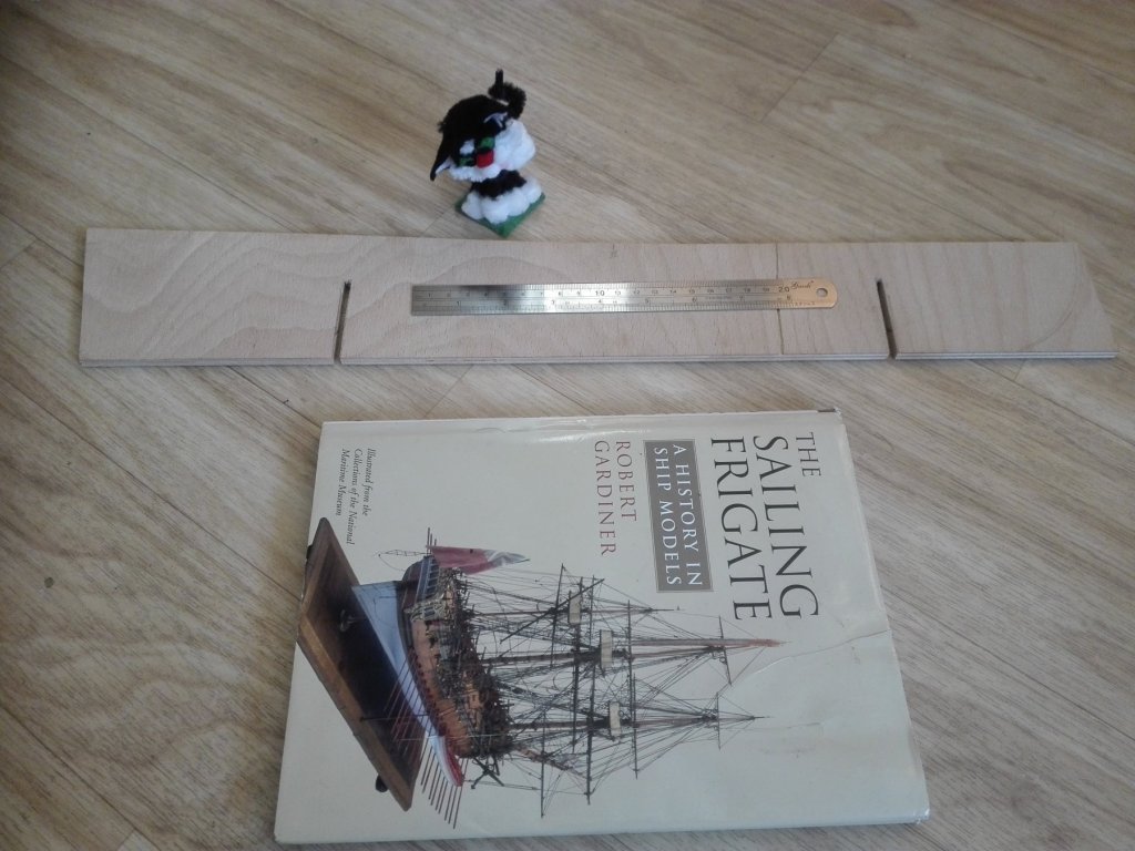
I searched around in Robert Gardener's book for any rules due to the pictured stands of the early frigates - but didn't find anything helpful with out - "There doesn't seem to be any rule."
-
The
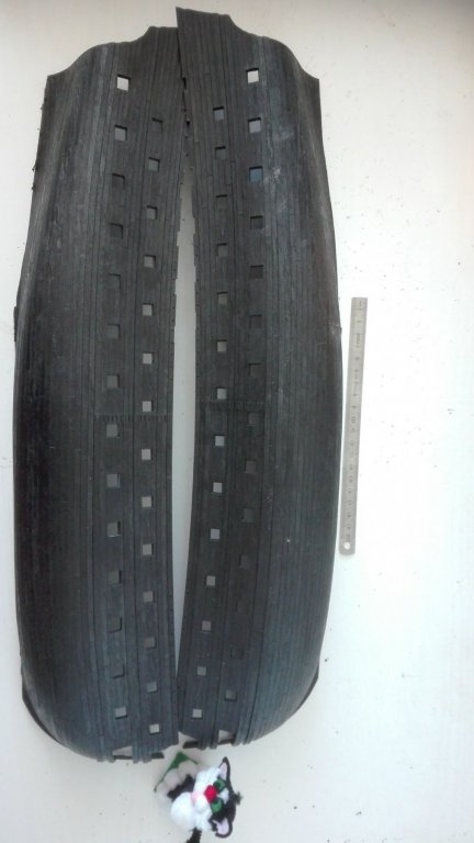
 centerboard is cut out and has to be rest trimmed ad the stem's round.
testplacing was successful. Only the stem keen must be cut off without destroying the hull. That is a real callange I think I'll first have to enclose the gap by the parts N° 27 & 28.
When the structure of the underwaterhull is ready and the enclosung 36pdr guns deck is fixed inside the I do hope that the hull is realy stabil enough to take the stress and is ready to be sanded and replanked.

Now I have to decide where to place the cuts for the stand. Due to this I asked for your help and then the foam block has to be cut by this measurements to draw the 1/2-bulkhead, that were added to the centerboard by wooden square cuts.
- mtaylor, EJ_L, CaptainSteve and 3 others
-
 6
6
-
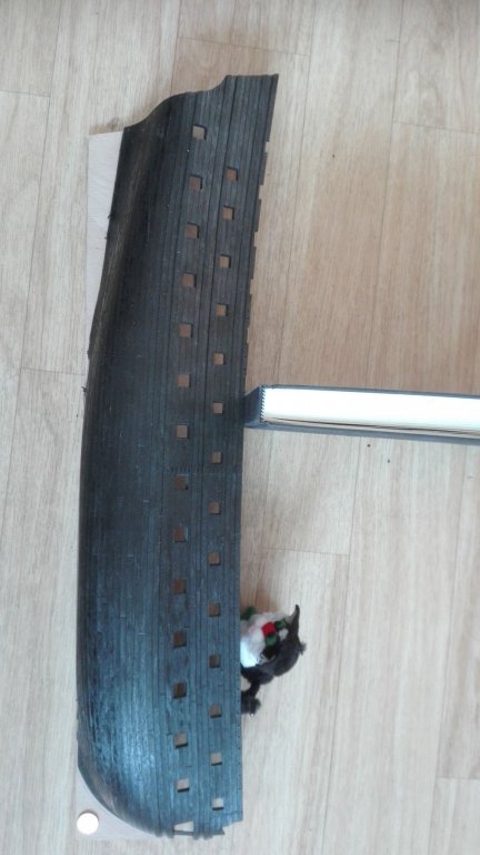
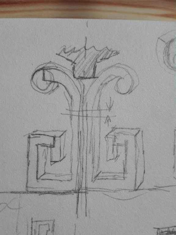
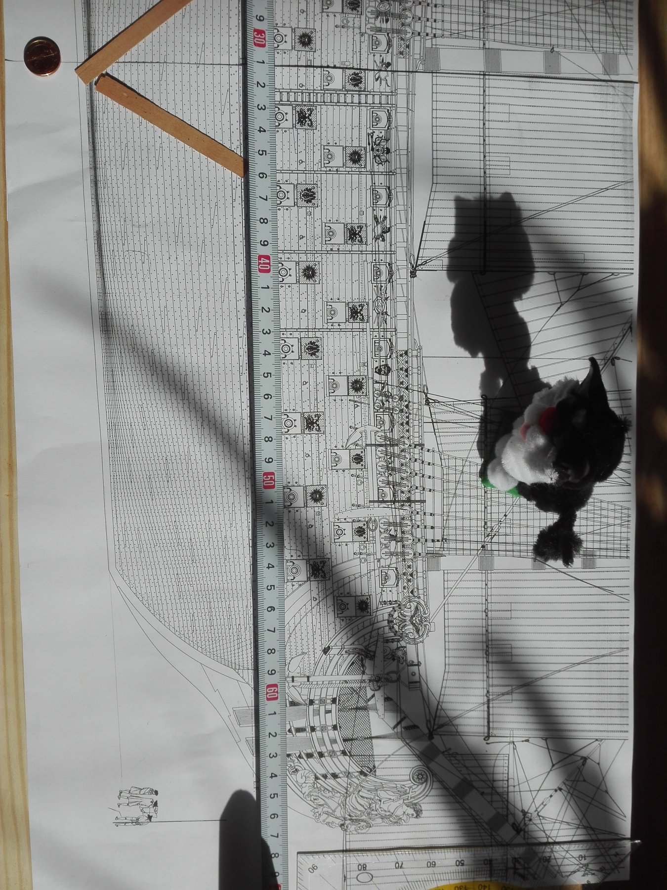
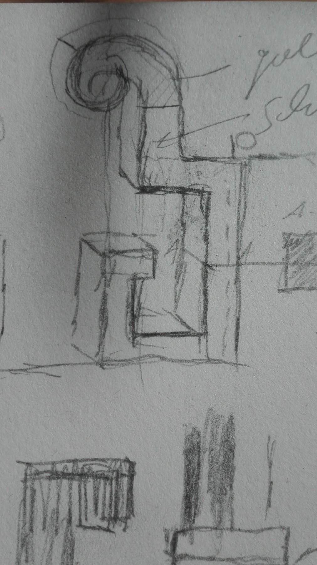
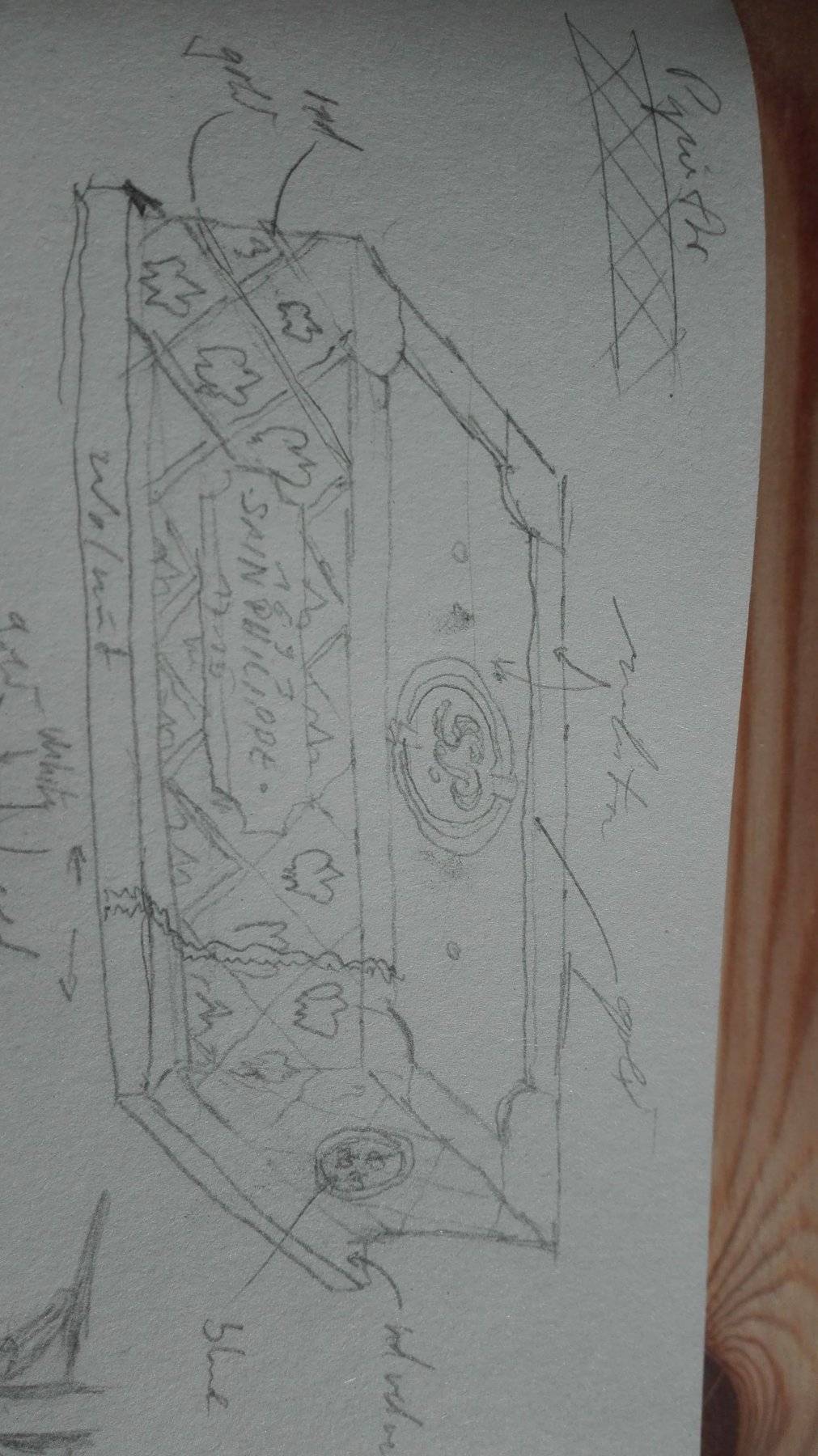
SoSo my question is WHERE to fix the stands columns???
Half the way from the lengths middle of the hull?
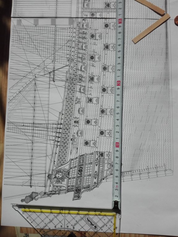
The hole hull model will be from the top lights to
the bowsprit cut-off 682mm long.
When I am going to take the half of both distances placing the stand (symboled by pices of vaneer) at the outside of the 1/4 length I do get
this.
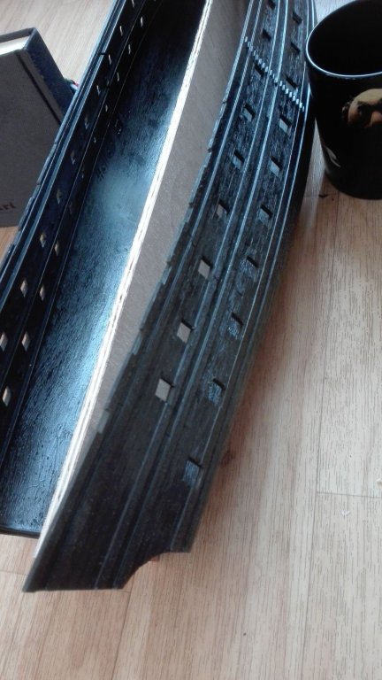
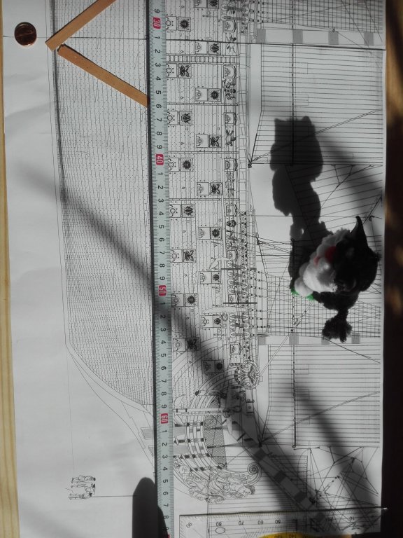
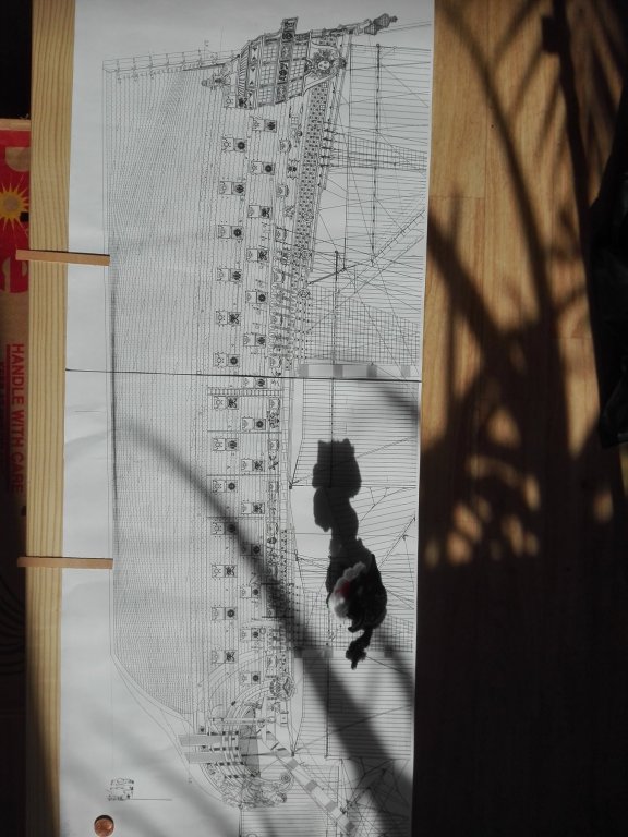
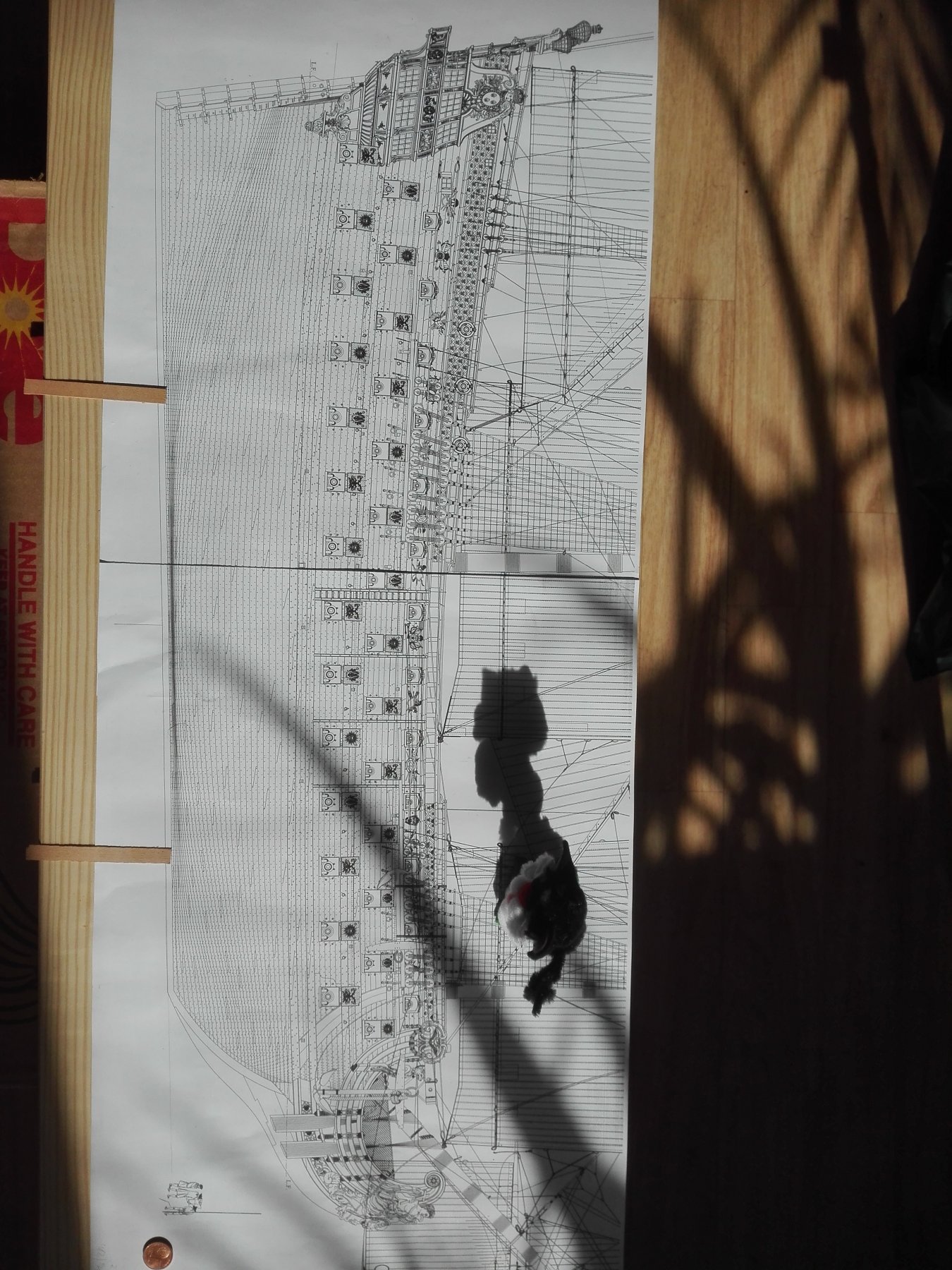
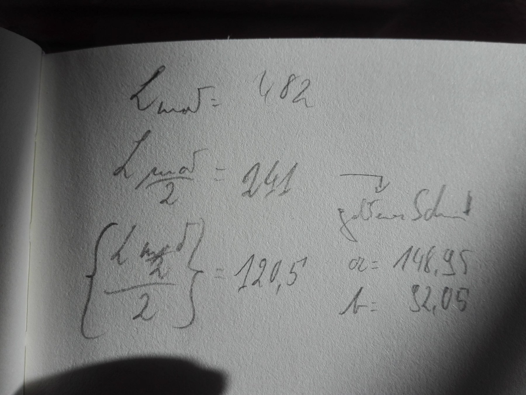
Then I thought about the good old rule of the Golden Section...
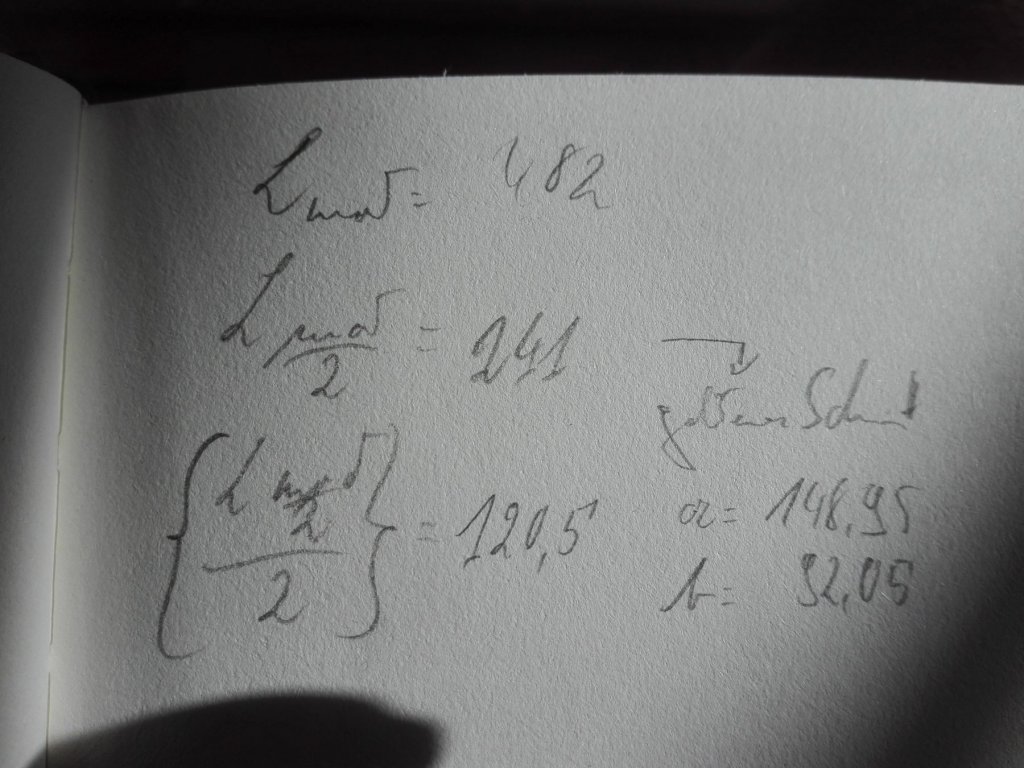
The math is this

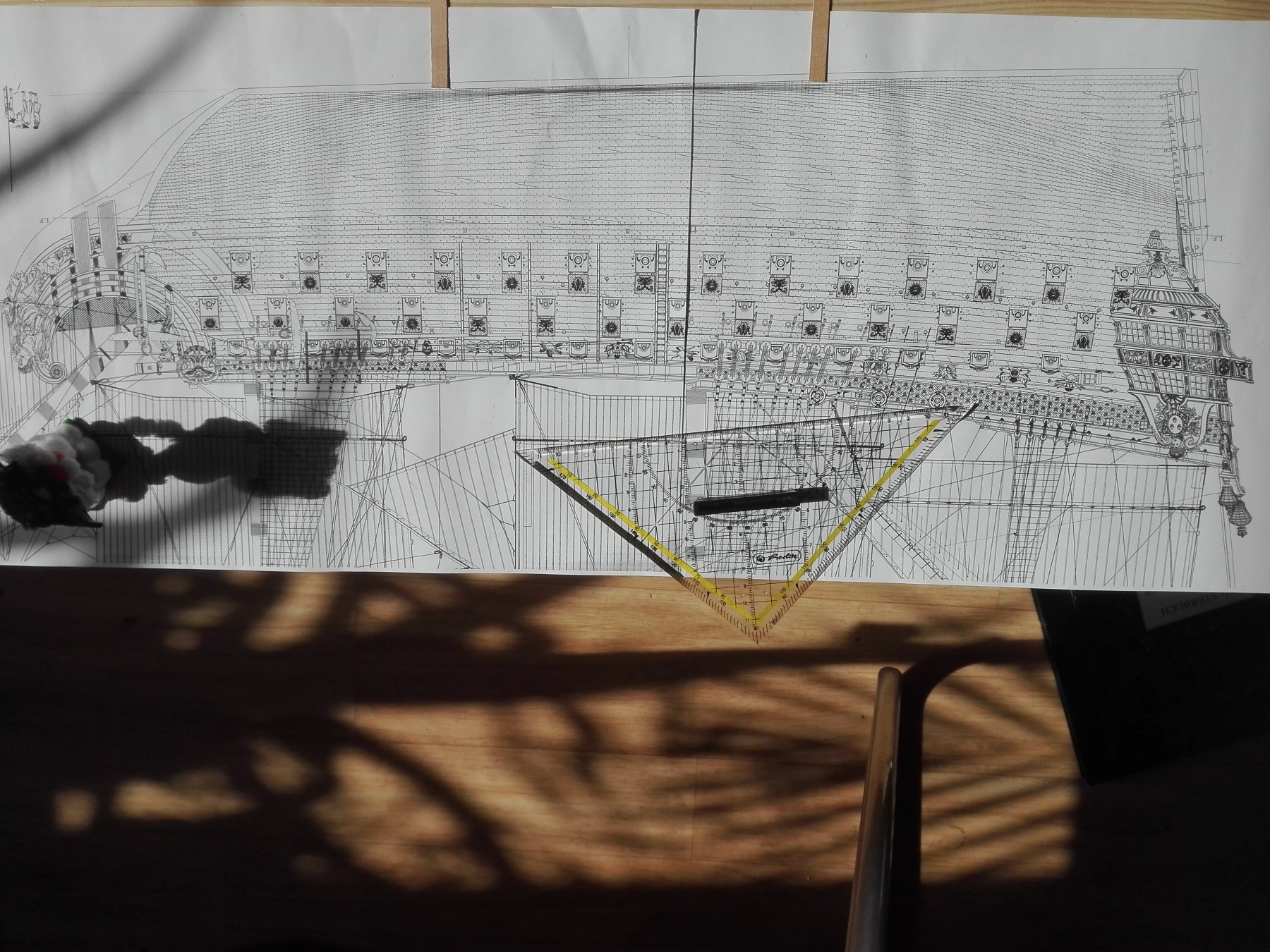
And this looks it like with the distance b
...and distance a
What placing do you think is right?
The long distance looks gravitating, dosen't it?
I do ask this aesthetic question now as I have to make the cuts into the middleboard to place the nuts for the working stand and later for the golden baroque stand.
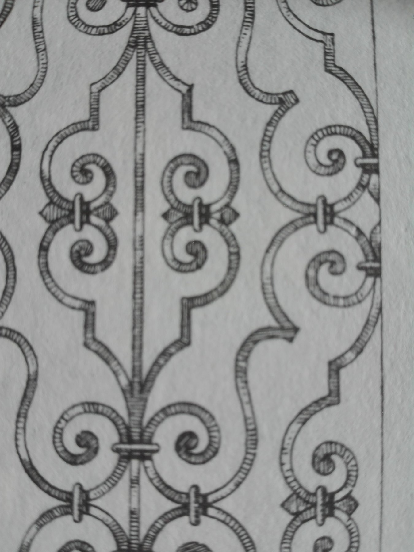
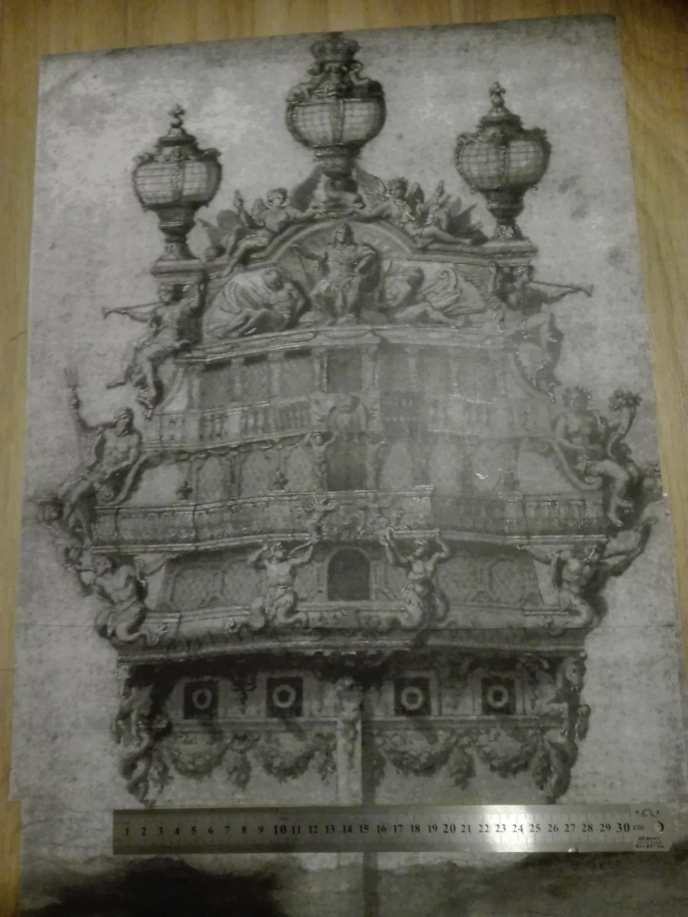
And my source of the stands idea -
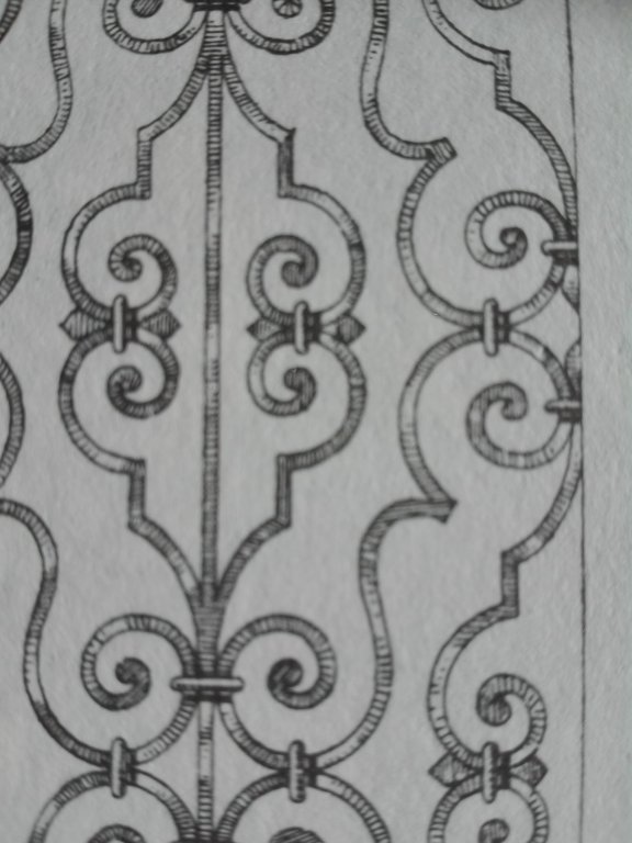
Here en detailes.
Sorry but my smartphone loads the pictures as it likes to do it!!!
- CaptainSteve, mtaylor, J11 and 2 others
-
5
-
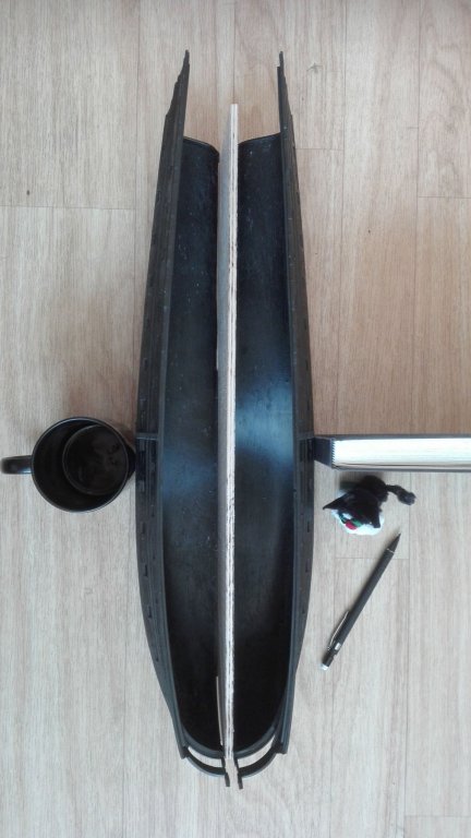
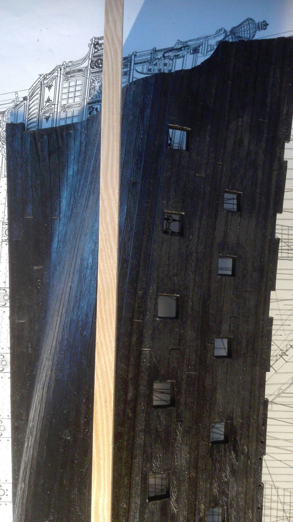
It is fulfilled...
There is no way back... now I have
I.
to clean the surface and cut the 6mm hardplywoodboard from keel to the LD with its 36-pdr guns. As I am forced to adjust the guns befor starting the 24pdr's MD.
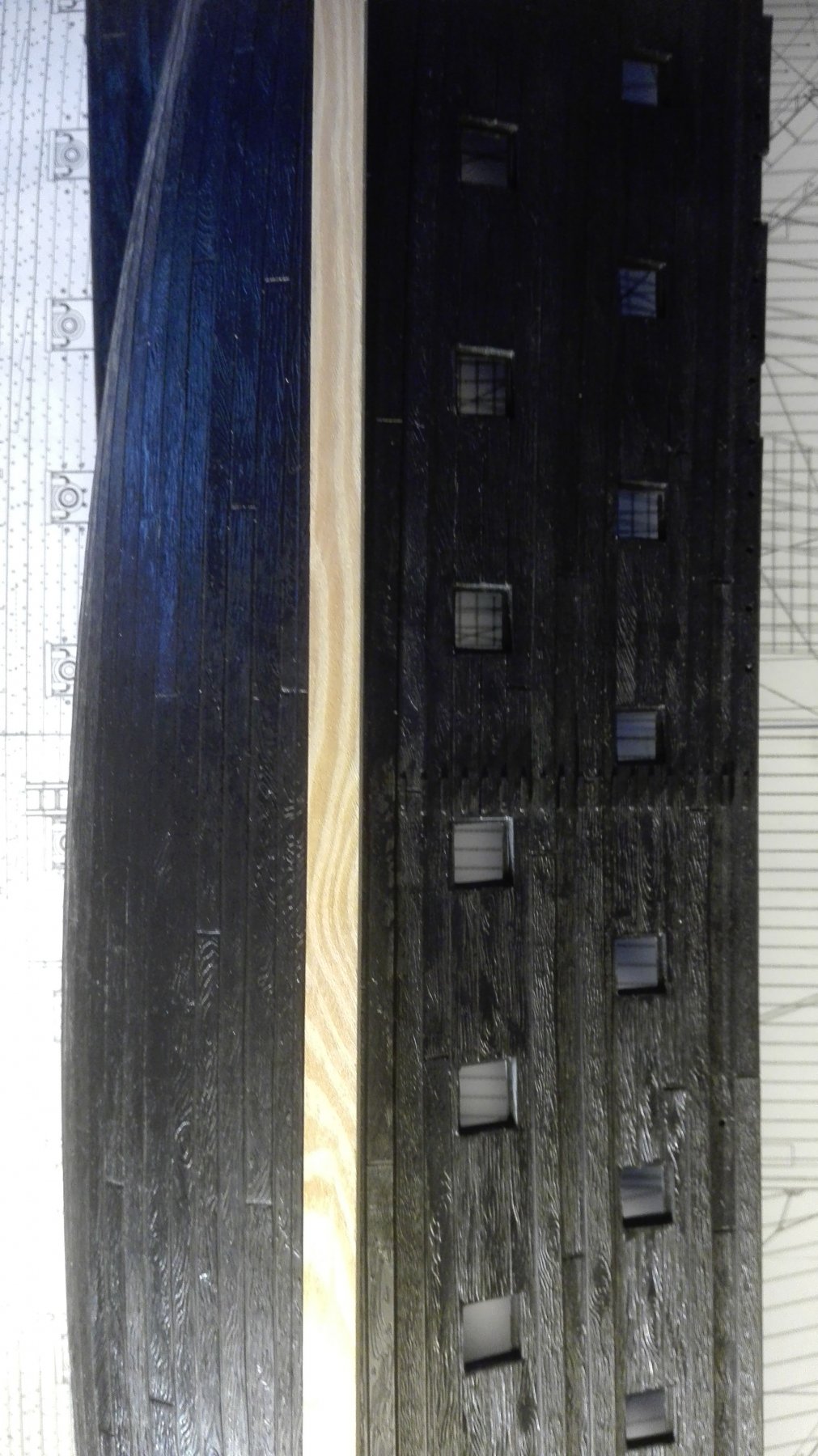
II.
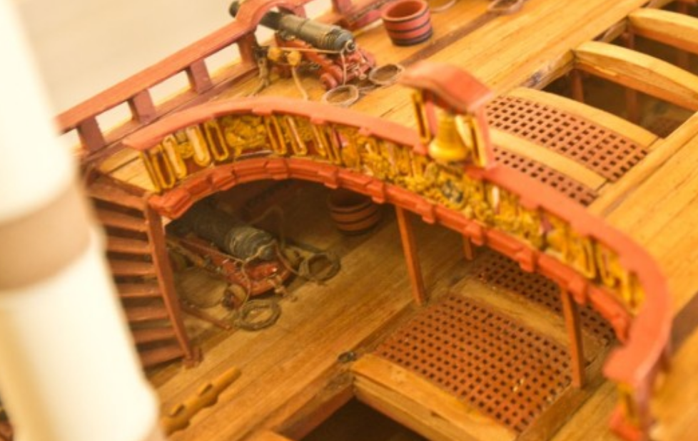
I'll have to get some ideas about the gratings down there and how many of it can be seen from above or peeking throug the gunports into the deck.
III.
To do this I'll have to scale down the Ancre plans from 1/48 down to 1/92. And I'll have to add some details 1/24, too.
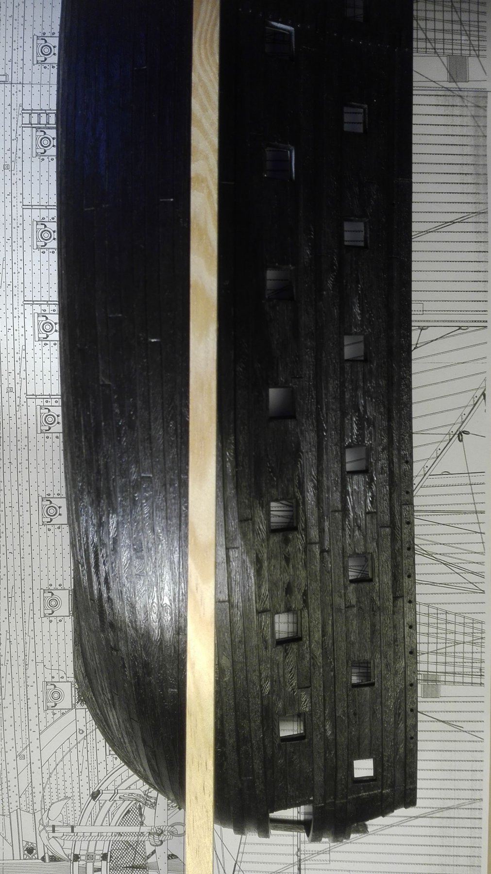
IV.
After this I have to add the new keel, stern and stem. The bulkhead'll have to be cut out and I need some inspiration how to camouflage this to people peeking in the hull with a line of sigth rectangular to the grills!
V.
All this needs a right sequence of steps to be done in the right order not to forget anything.
VI.
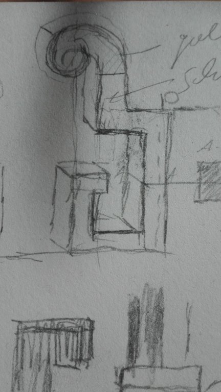
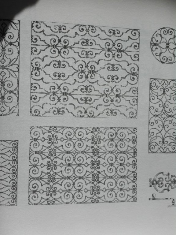
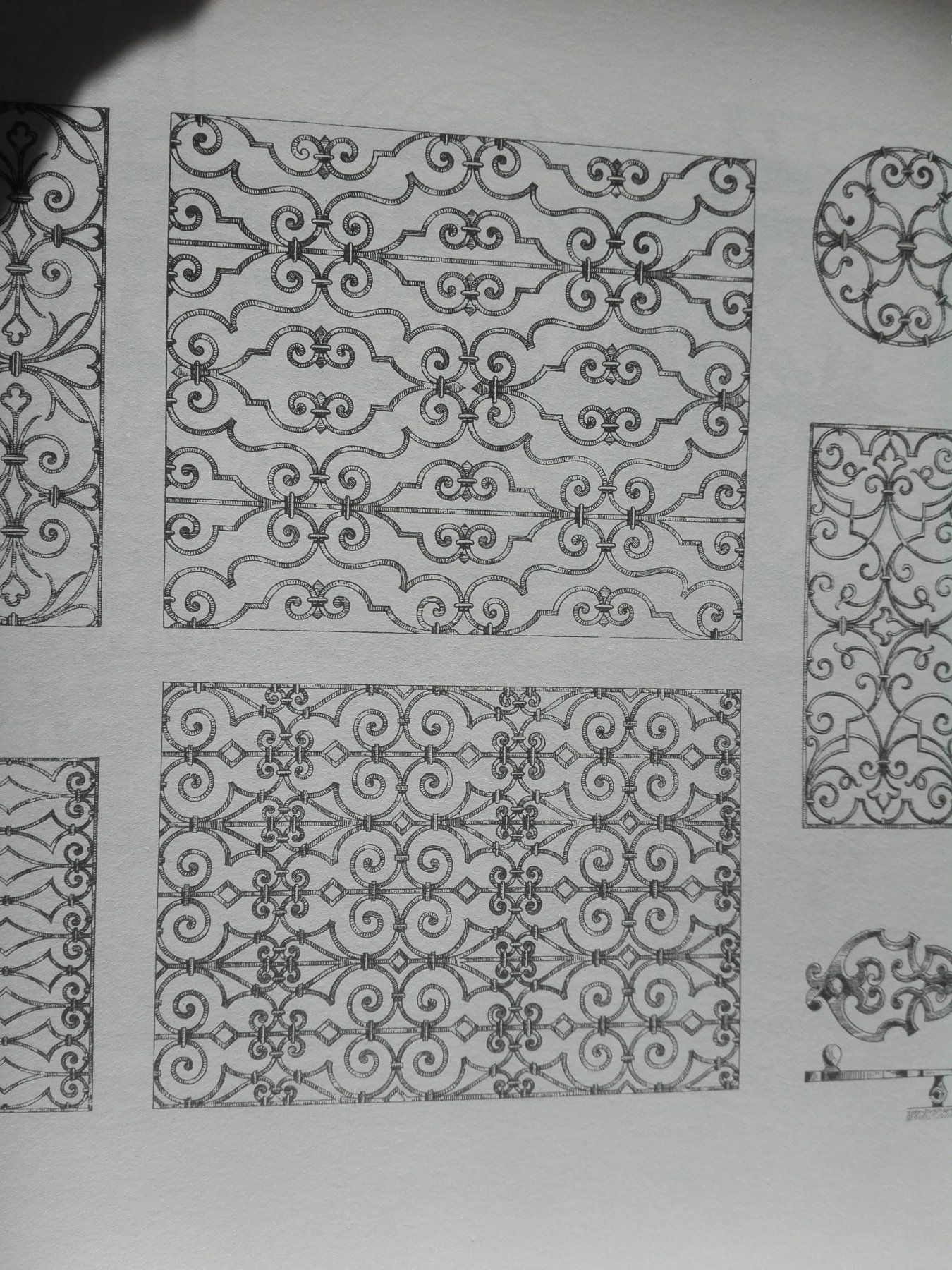
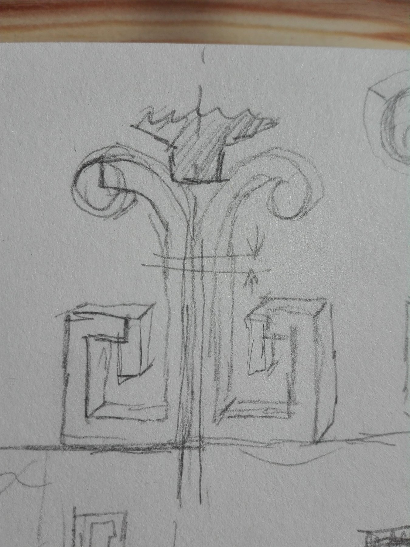
The threaded rod and the fixing nuts to fix it have to be inplemented in an secure AND aesthetic way and the scew has to be camouflaged away. This stand can be easily
build in a long and a short way (near stem and stern) - it is a detail from a blacksmith works book - a small takeout from a gritdoor in Prague typical baroque kind of metal work.
VII.
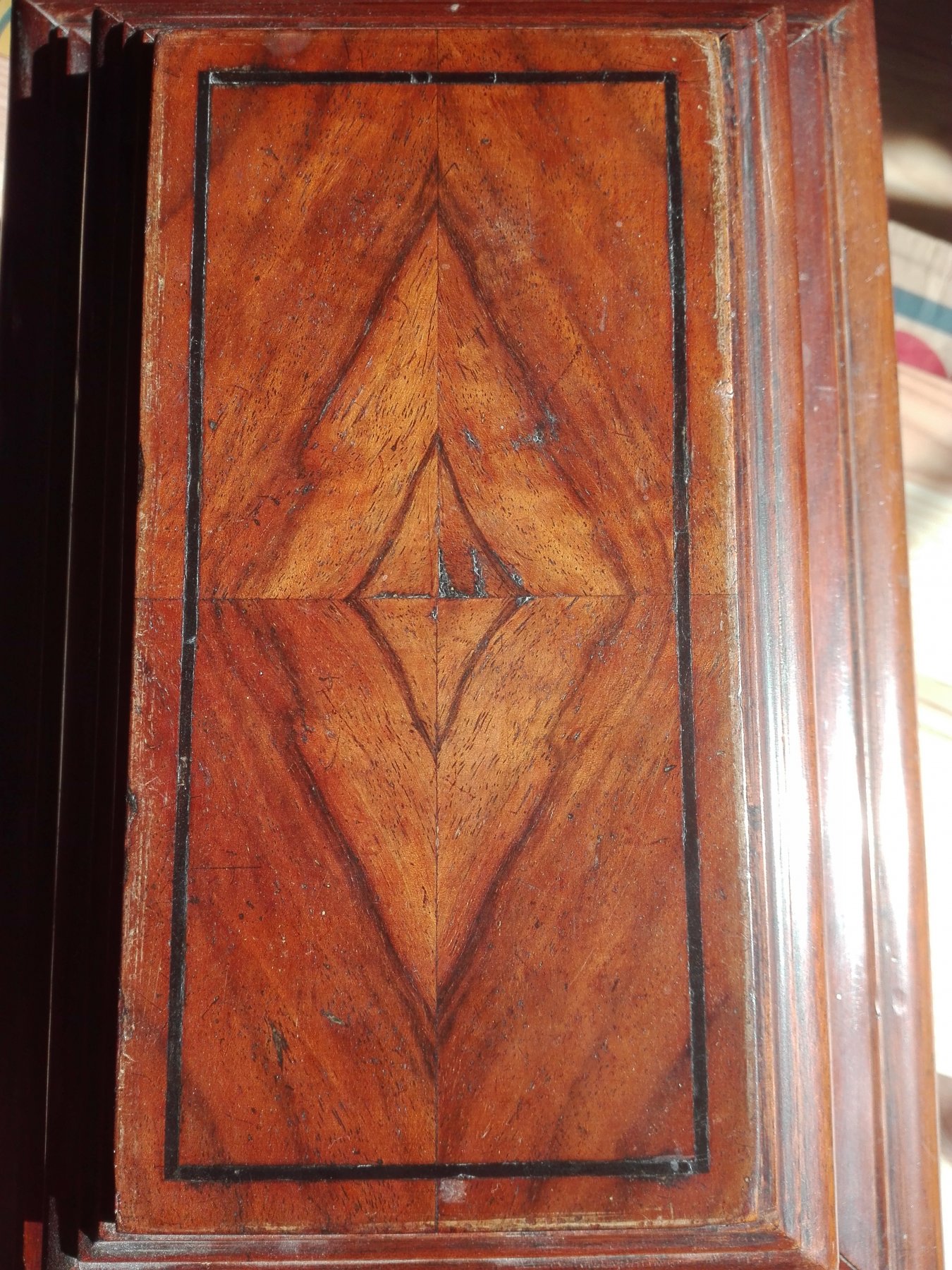
The only thing I have got is the idea for an aesthetic post to place the hole hullmodel onto reacting the fleur-de-lys grit of the UD. The idea of a white topside is changed because of the white unwater part of the hull - so I have to take a darker more structured wood like in my
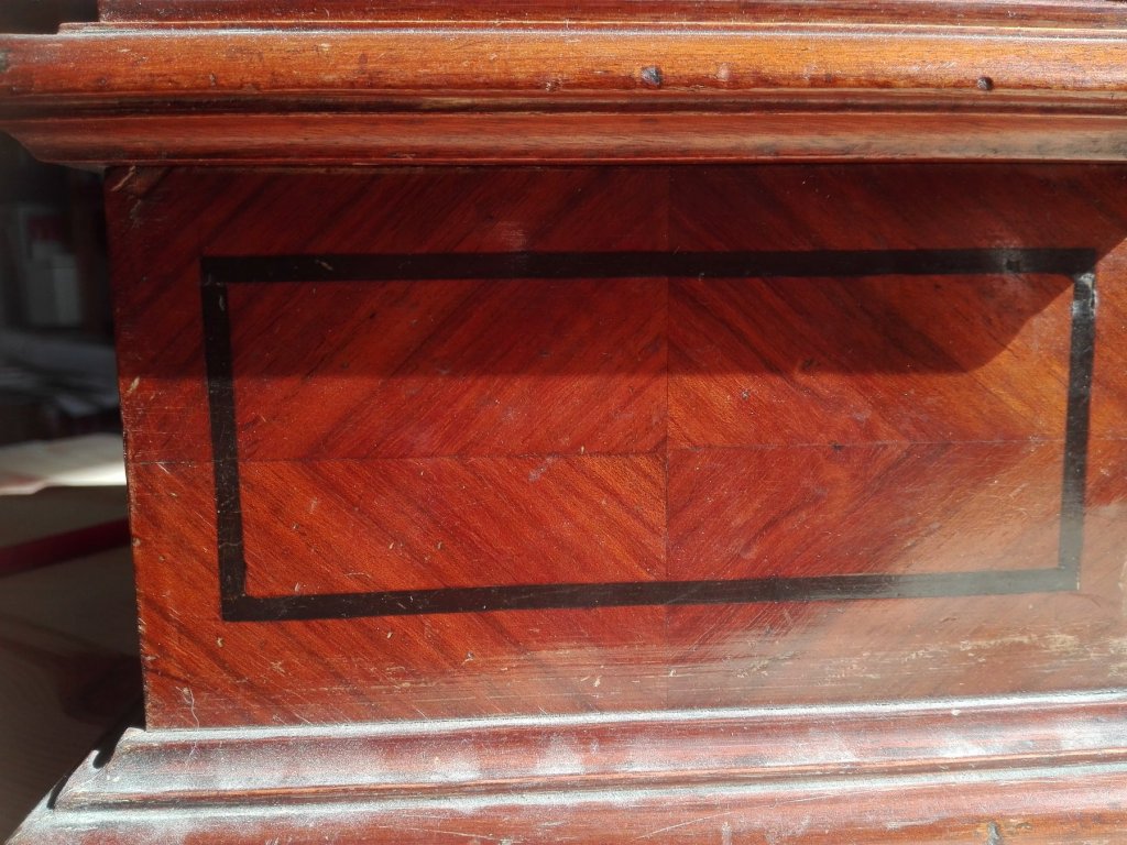
cigar box side or

more structured topside
to get a good and warm conteast. The grit from the f-d-l will have to be continued around the edge (at the dark line) and being converted to a kind of patterns ranking into to wood at the side but not covering it too deeply.
So let's start - a plenty of work is waiting.
-
Thanks a lot, Marc, I'll try to do the cutting off of the keel tomorrow at the testing parts. As I did get a good knife I can now start with the foam block to cut him in slices and then use it to saw out the bulkheads.
If this works I can start it onto the real thing the Heller hull cutting away the keel.
- Hubac's Historian, J11, EJ_L and 1 other
-
4
-
Hello,
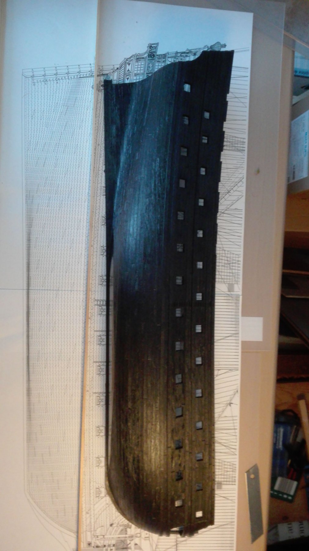
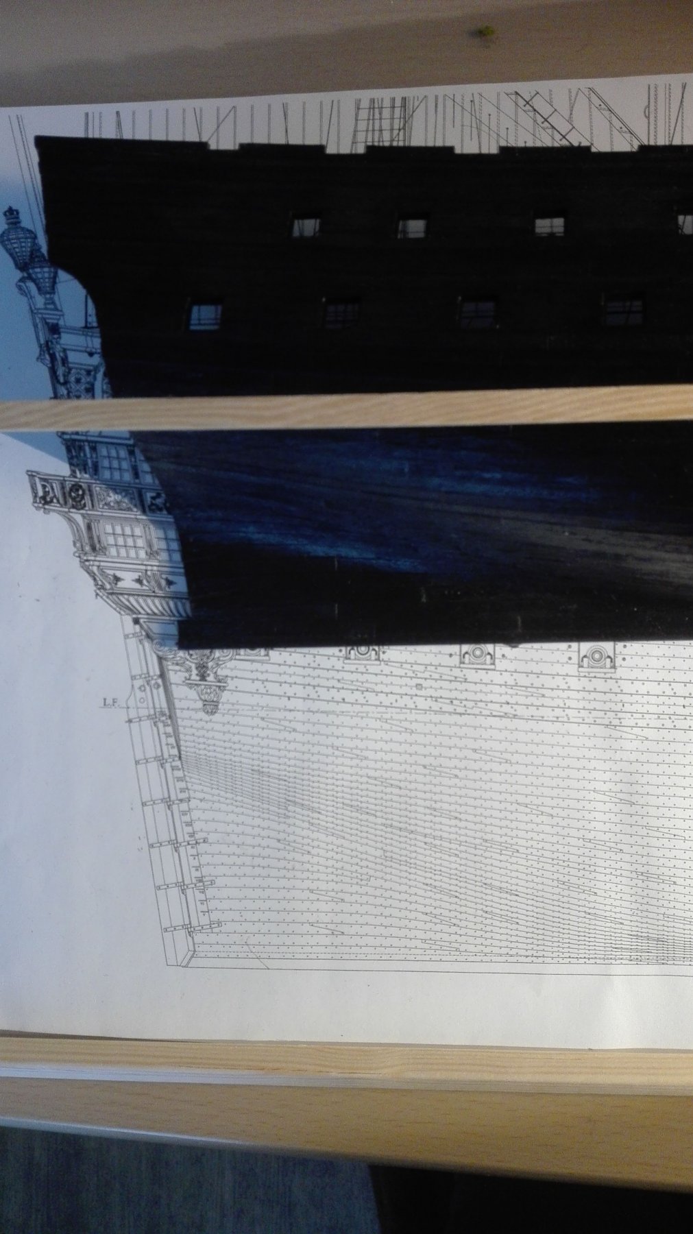
The CWL ist the next source of trouble. The keel of the kit is CWL-parallel - but
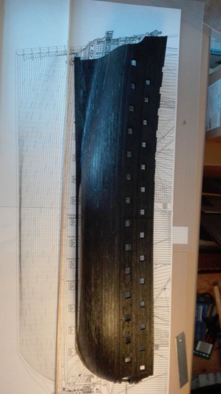
he SPs keel rises towards the stem.
And when I change the CWL the rest of the hulls planking has to be changed,too.

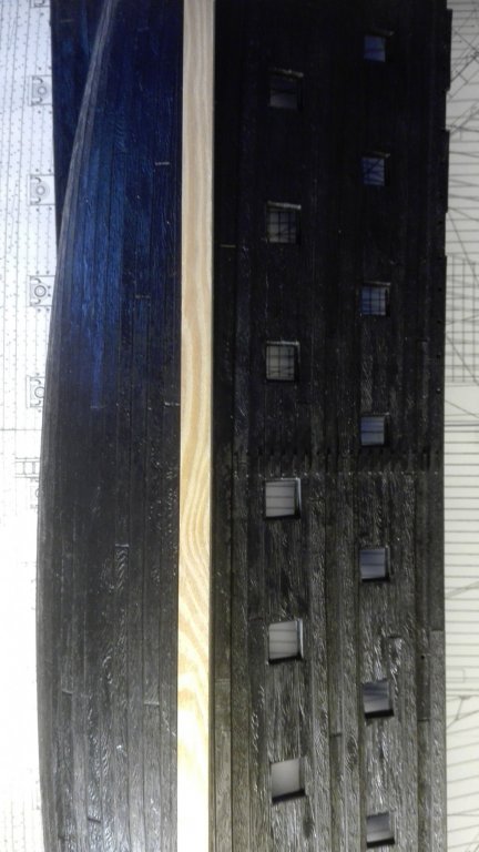
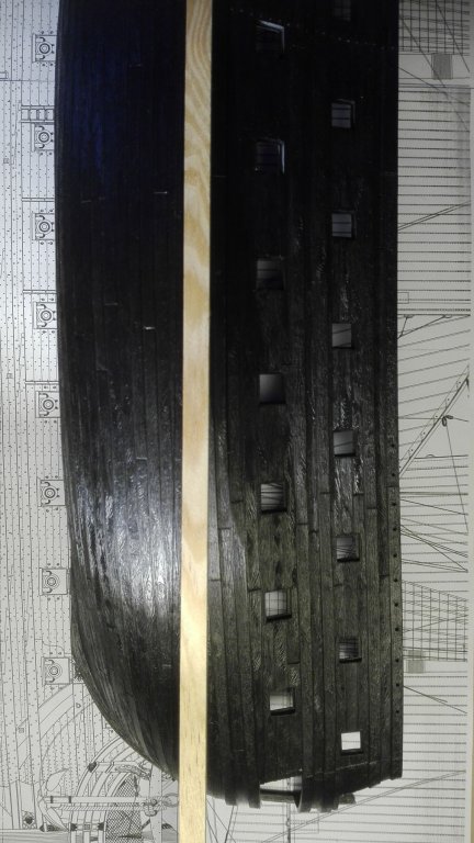
So the wales have to be relocated aft... so the planking - as it runs parallel to the wales is to be bent, too. I'm so happy I had had decided to do a new planking at all - now I get the first advantage of it.
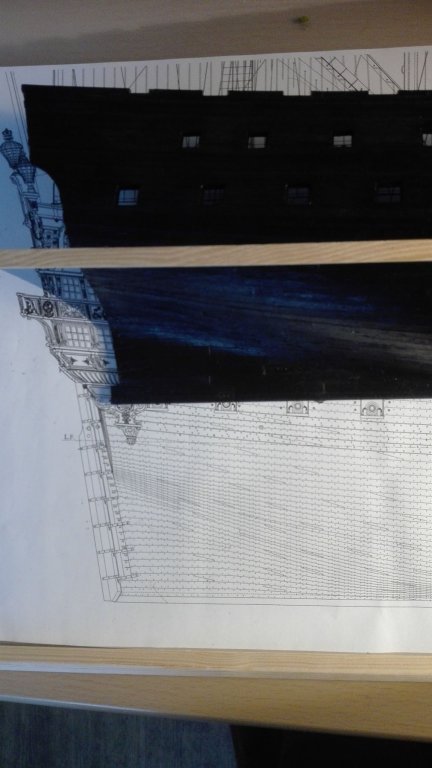
Happy Easter!
PS: here it is more obviously:
- EJ_L, mtaylor, CaptainSteve and 3 others
-
6
-
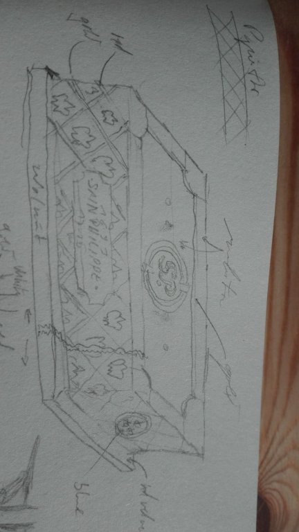
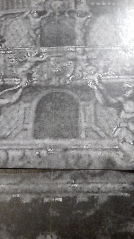
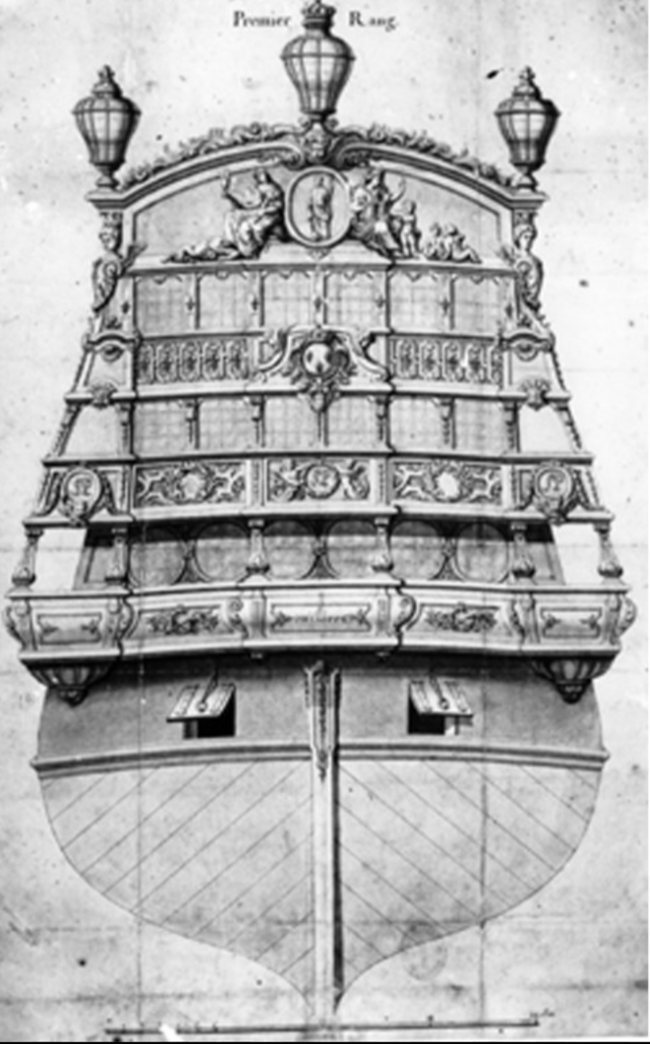
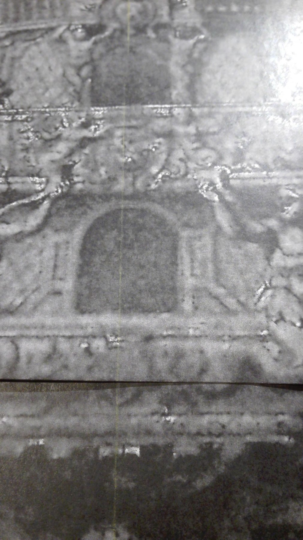
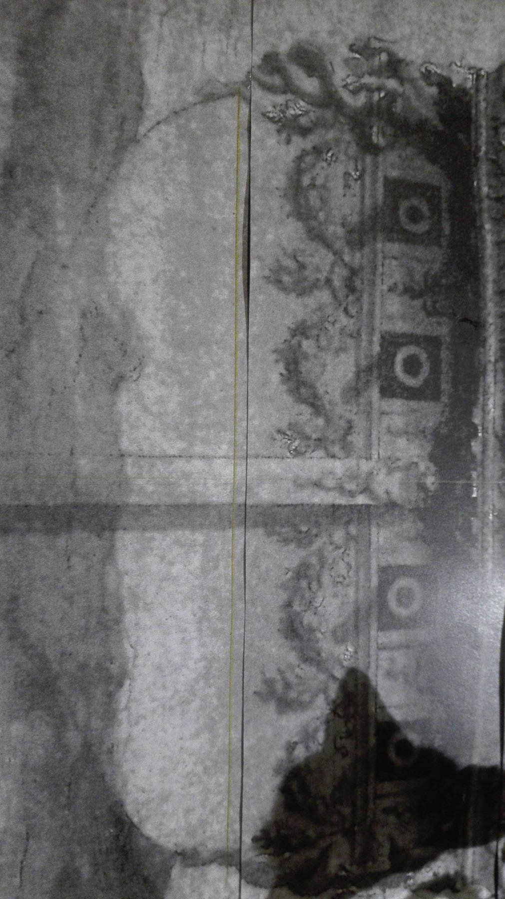
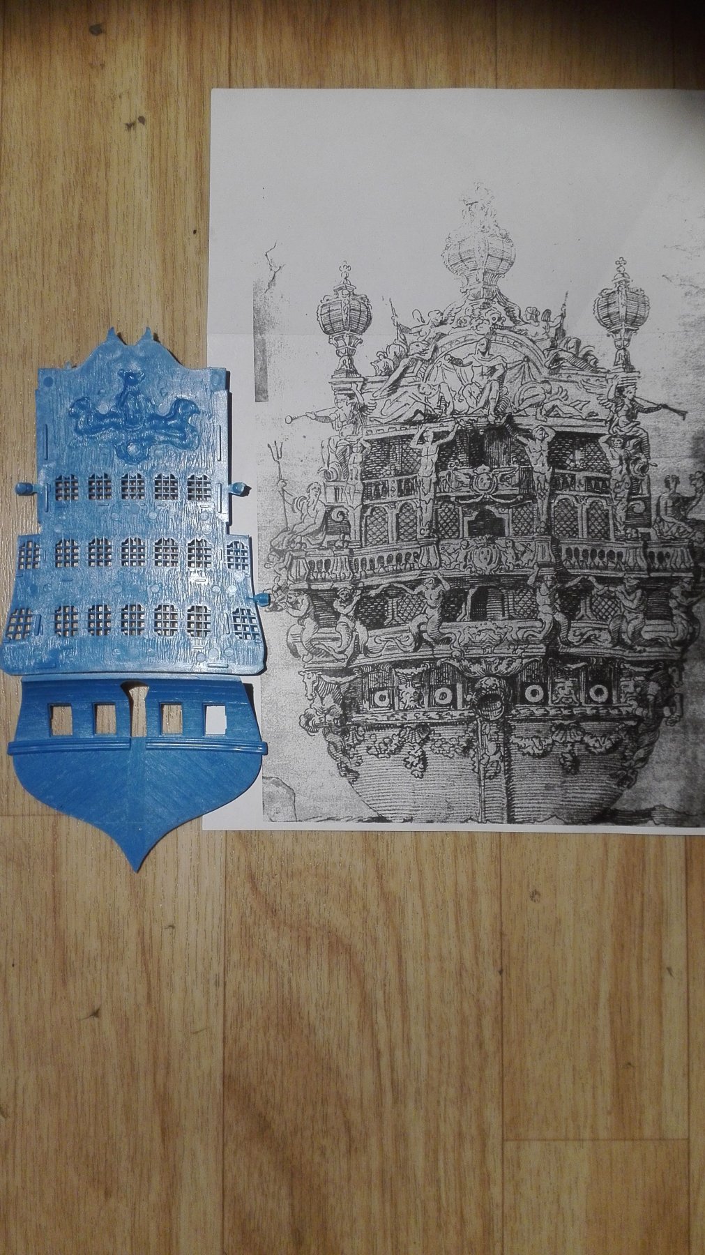
Yes, Marc, that is an interesting point you pointed out! The beloved balconies.
When we look onto the eventually original drawing of SAINT PHILIPPE or (more likly) her sister TONNERANT
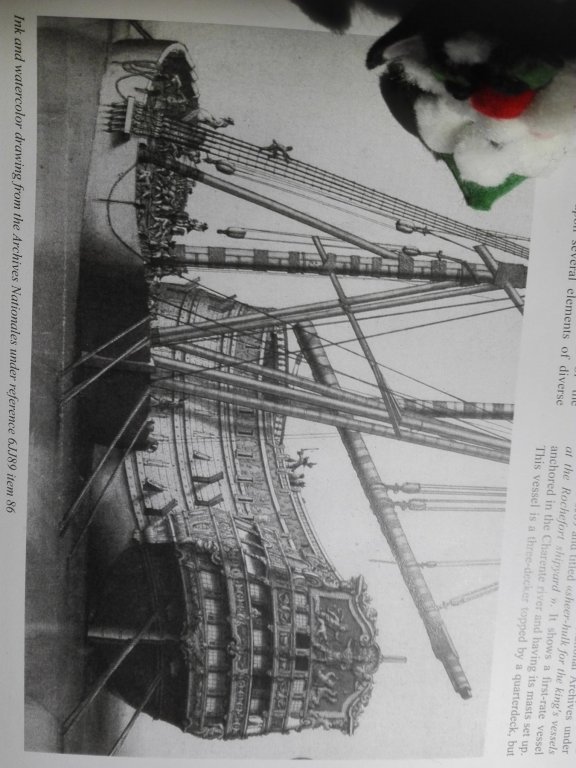
we do find several indices for two balconies and some comletly open galeries on both sides. The picture is an ink and watercolour called "sheer-hulk for the king's vessels at the Rochefort shipyard" (Nat. Archives 6JJ89 item 86). And beside the interstinhg hulk showing the narrow of every balcony or the little distances between transom and parapet to us. So I'll try to orientate my further creation of the transom by this contemporary guidline drawing.
-
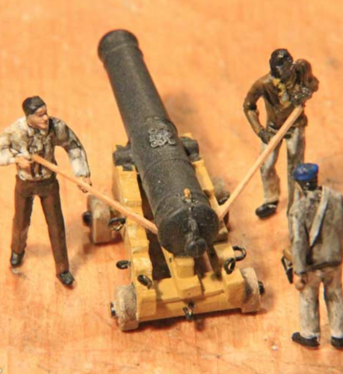
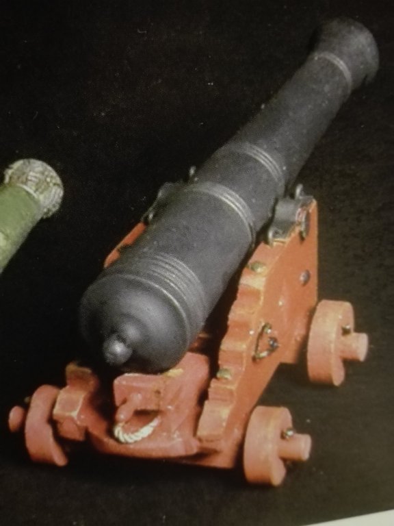
Hy Marc, there is a differe ce between rust and patina. The bronze guns patina closes the surface and ended the process of oxydation. The rusting of iron (without grey or cast iron as they deal like bronze) destroys the hole material from solid iron to pure rust.
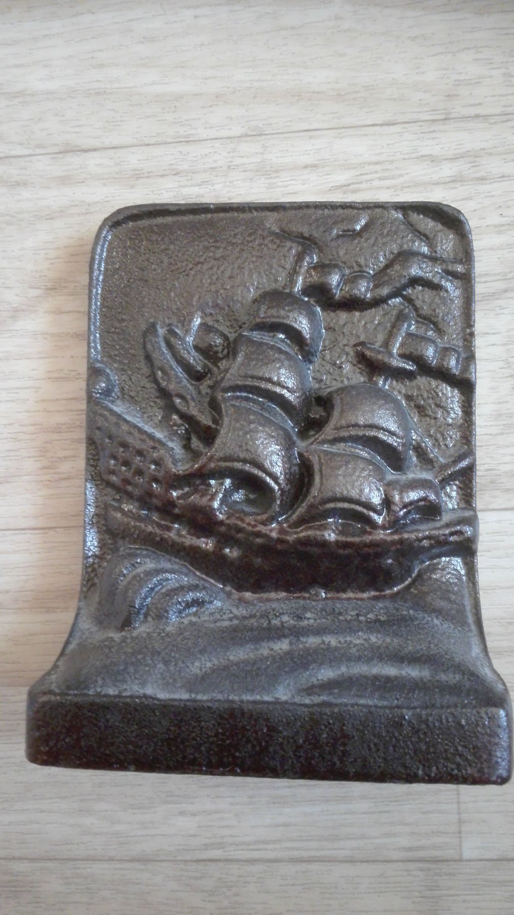
To avoid this the iron guns were brought max. to a cherry red temperature and painted with linseed oil to conserve them by a coat of waterroof surface. These is easily simulatet by painting the barrel in an acrylic colour matt black and then a number of layers of brown ink (Citardel) is added I have got some book supporters that were coserved in this way.

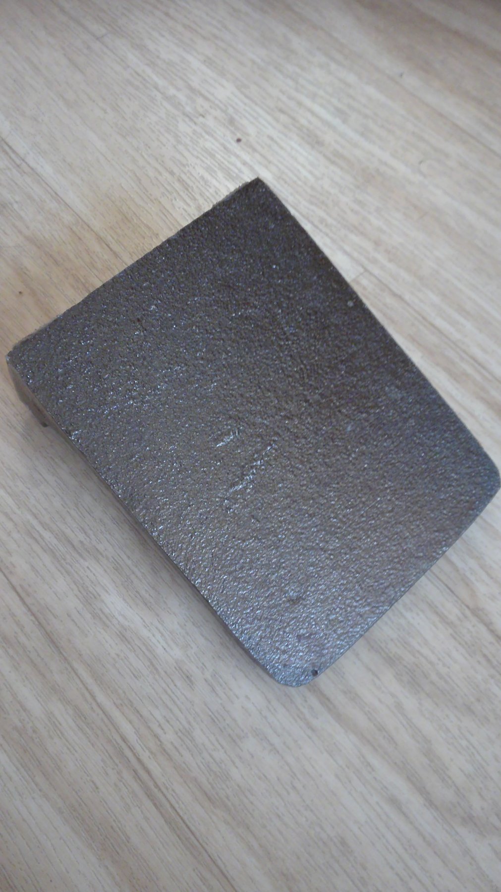
Here a front and
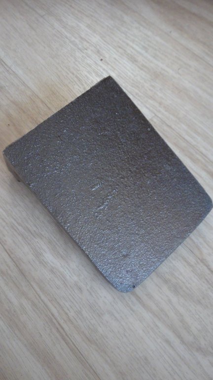
back side illuminated by day light
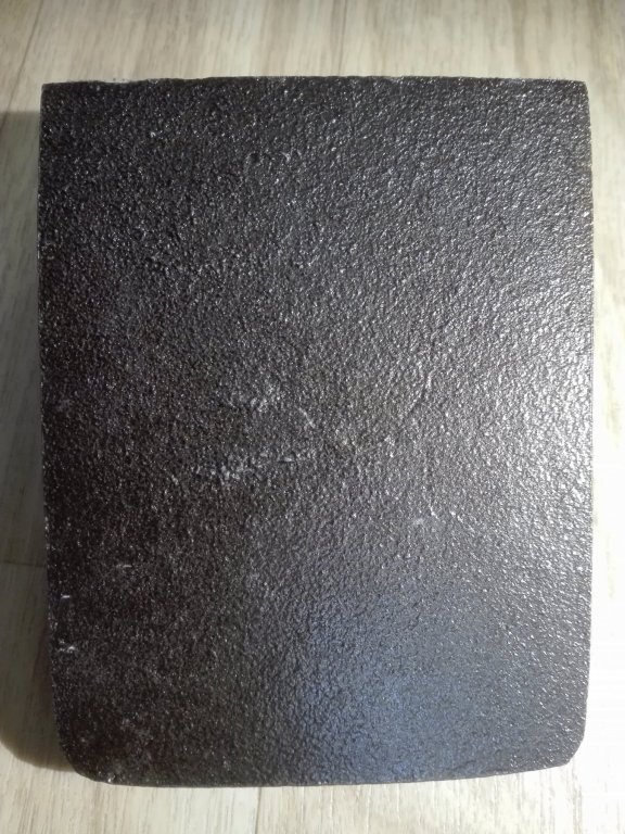
And by hallogen to show the deepness of the oil.
Hth.
- EJ_L, mtaylor, CaptainSteve and 2 others
-
5
-
Dear friends of the baroque ship building!
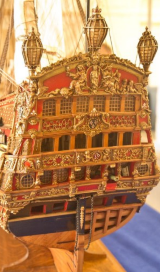
The

original drawing of SAINT PHILIPPE and

Mr. Lemineurs model are showing some differences. In particular at yhe balconies.
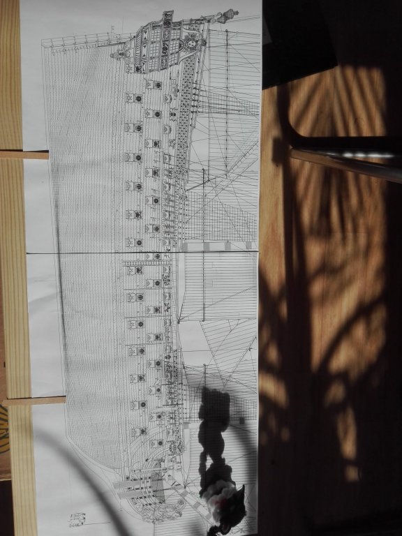
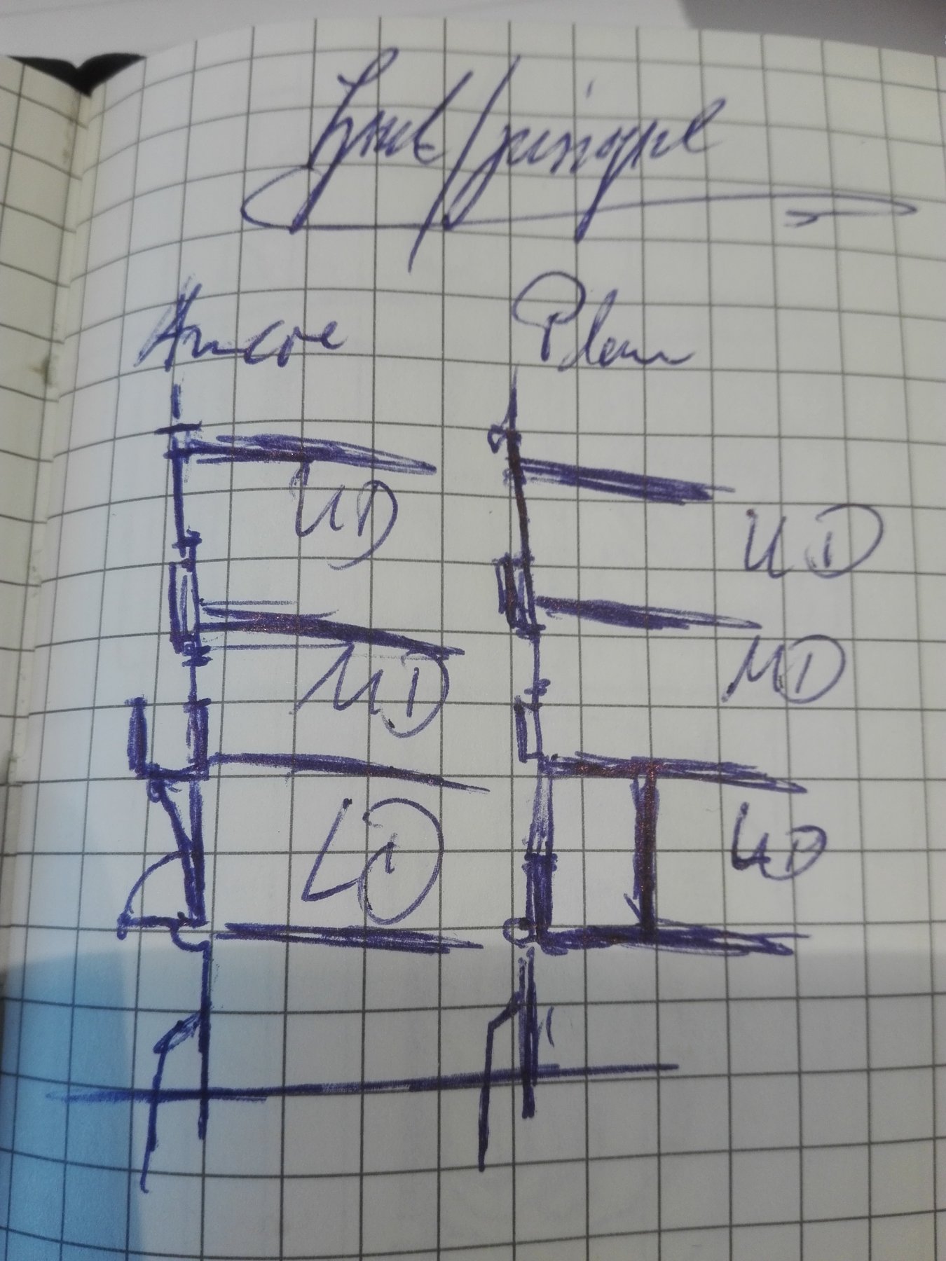
In my linchtime I was able to doodle

a rough side cut drawing (LD=LowerDeck/MD=MiddleDeck/UD=UpperDeck) - thevAncre/Lemineur plan on the left to show the differences to you. Mr.Lemineur liftet the balcony from the LD up to the MD - to ace the gun stations in the LD cabin. I am not happy about this.
What Du you think about this?
- mtaylor, CaptainSteve, EJ_L and 1 other
-
4
-
5 hours ago, shipmodel said:
Marc -
Best of luck finding the painting in the Parker gallery. I have my fingers crossed for you.
I was wondering, though, why you are choosing a verdigris color for your cannon. The green is a function of the oxidation of the bronze - - - rust! I have a hard time thinking that the officers of a first-rate king's ship would allow the sailors to slack off so much that the guns would have time to rust. If they are rusty outside, they are probably rusty inside, and that can seriously affect firing accuracy. Cannon in museums are always green because no one is cleaning or using them. I have always opted for the deep reddish gold of fresh polished bronze.
Whatever choice you make, I am sure it will make the artistic statement that you want.
See you soon
Dan
Hello Dan,
the inside of the the barrel was protected twice - by some graft in the front and often additivly enclosed by sealing wax to keep wetness out.

And the inside ship opening to fire the gun was covered by tar and a lead tin (look above)
.
Your ideas about cleaning the guns are correct for the British RN but the French ships often saw actions (as my SAINT PHILIPPE) once in lifetime. So the mainly layed moored in the habour bassins and started to be rotten to be rebuild later on.
So if the gunbarrels on a war mission were cleaned and polished - I would say "Definitely!" But in the mooring time in habour it is very questionable. Depending on the captain, the number of sailers he has got and if the ship is a "Primeure rang extraordinare" laying there as ROYAL LOUIS to impress foreign visitors.
- shipmodel, CaptainSteve, mtaylor and 2 others
-
5
-
53 minutes ago, Hubac's Historian said:
Thanks, Dan. They’ll look even better in ver-de-gris patina; all of SR’s guns were bronze. And I’m cautiously optimistic that if I get the green wash right, you’ll even be able to see the tiny fleur-de-lis that are moulded onto the barrels.
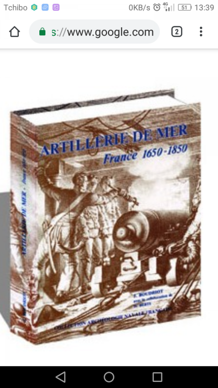
I think you have got any reason to be optimistic - I just read your lines stood up for you and leaved through the SAINT PHILIPPE monography and tracked down this

Meaningfull examples.
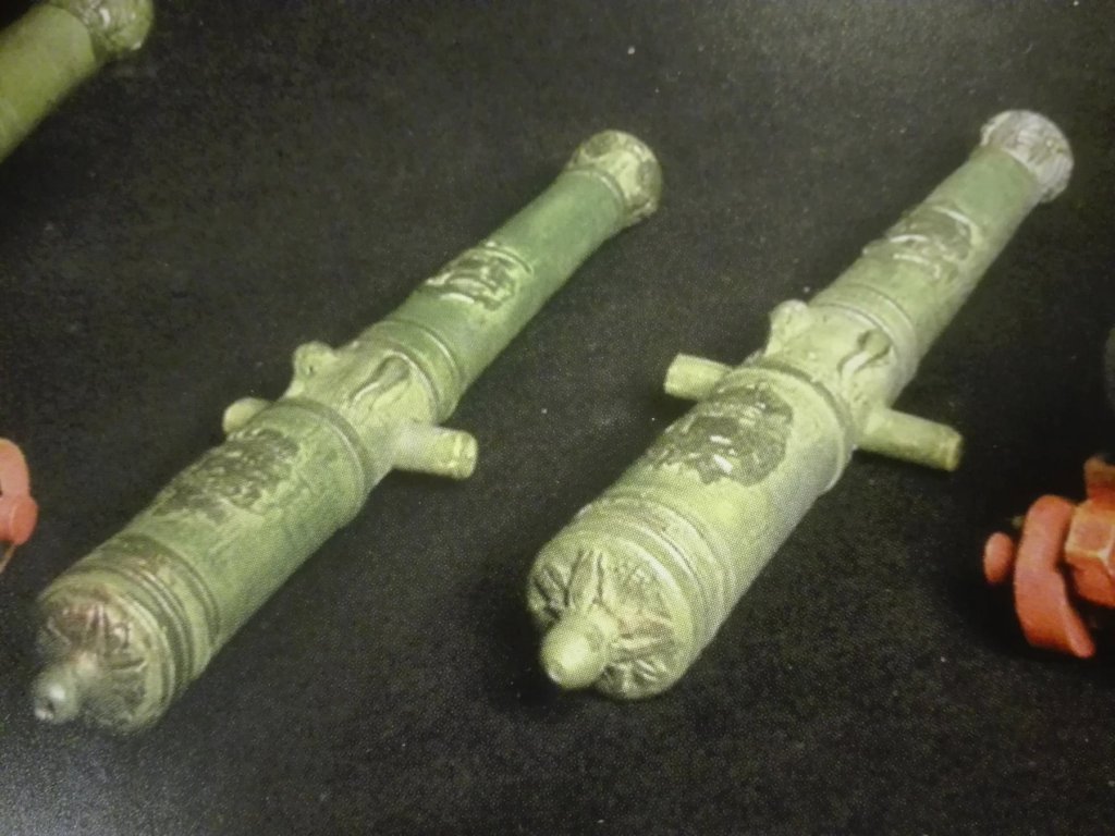
Of ordonance in bronce patina... I am thinking straight about some colours


the bronze or gold should be mixt to mixtur after you personal taste and meaning of bronce.
Some deep can be ar hived and arranged with some
camouflage green ink by Citardel.
To wash the red carriage I do use
Looking like a heavy Bordeaux wine making wounderful deepness to little assecoires on any red underground (as long as it is not a Ferrari red-orange).
The barrels may get a source of misunderstanding and bad interpretation .
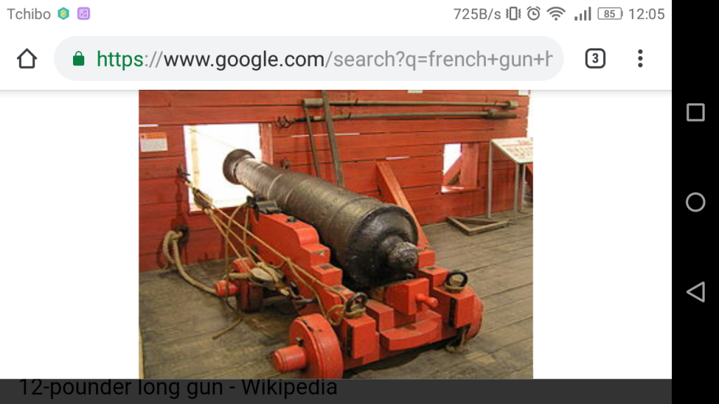
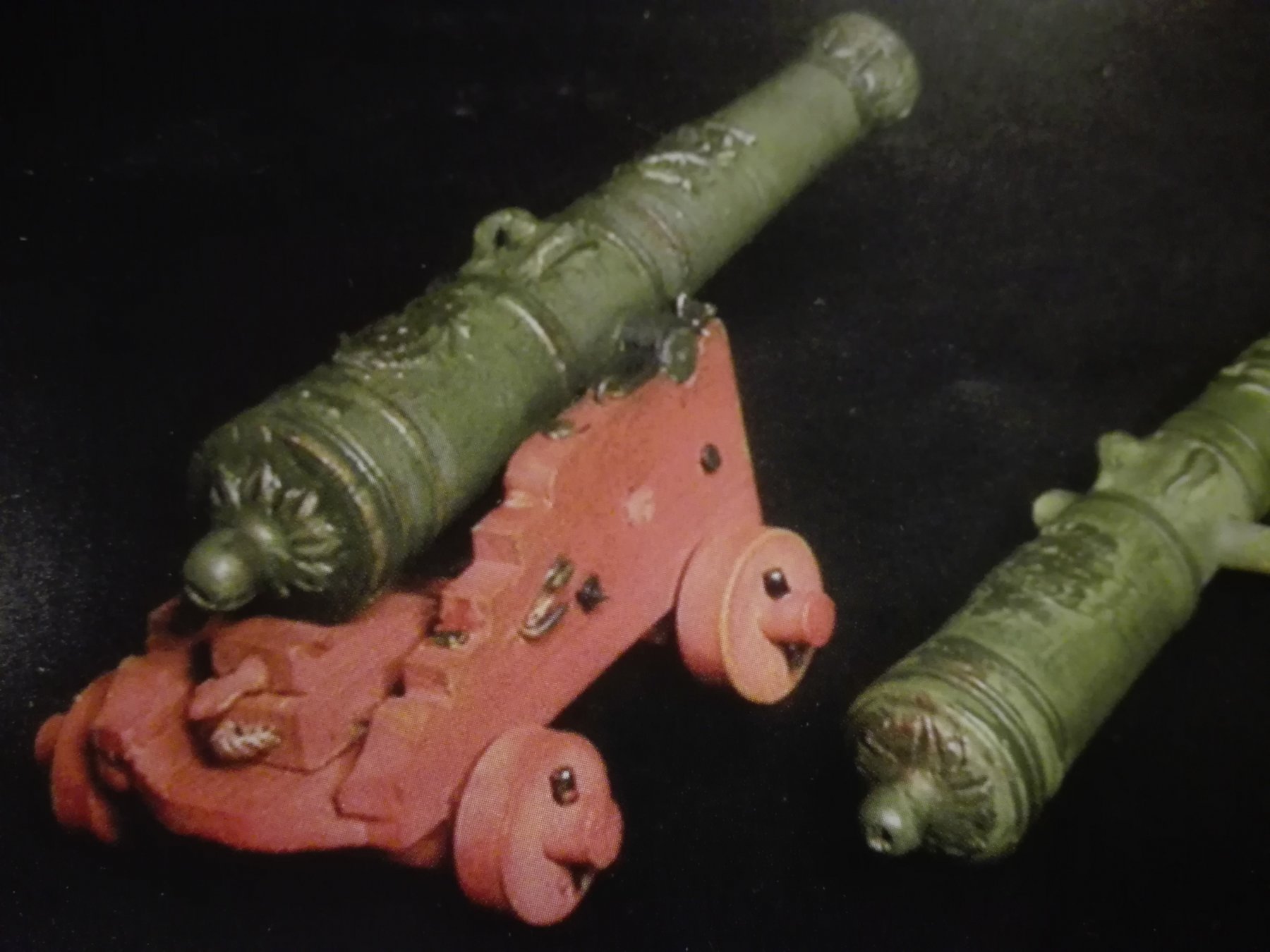
Here an example of a
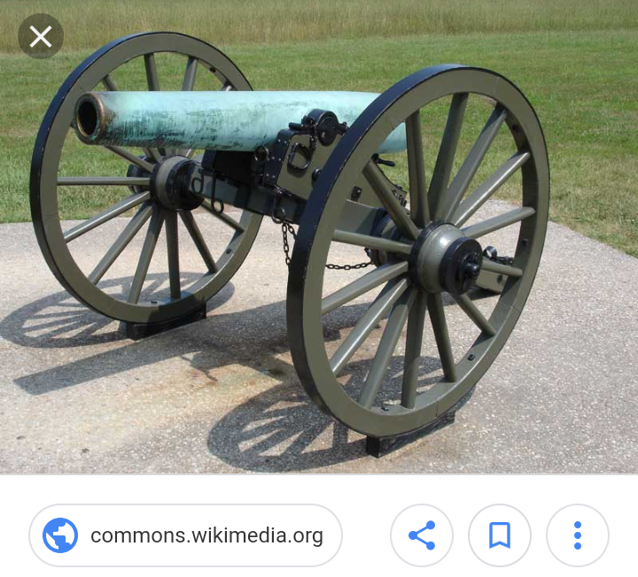
CSA Napoleon bronze gun barrel (on some refurbished carriage) and other
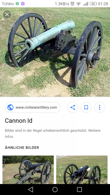

bronze barrels to get some idea of the colour! Or did the mates ordre their seaman to polish the barrels as a wayof passing the time without scrubbing the deckdown to the beams...
Perhaps you have got some examples near to you - best may be to look for some bronze guns under the salty sea air conditions in some coast fortress monument to get some realistic prototypes to see.
H.t.h.!
- EJ_L, CaptainSteve, mtaylor and 3 others
-
6
-
The gun barrels look fine, Marc!!! I still think you shoud make them working due to any problems with the IPMS -jury
")
If they didn't agree to your arguments 😖 it is always an U.R.R.

And about casting them I three rows of 12-, 24- and 36 pdr groups
save some time - quality will be given by good resin.
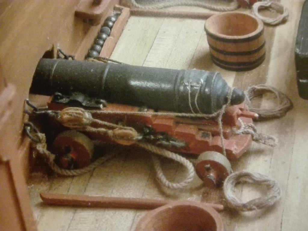
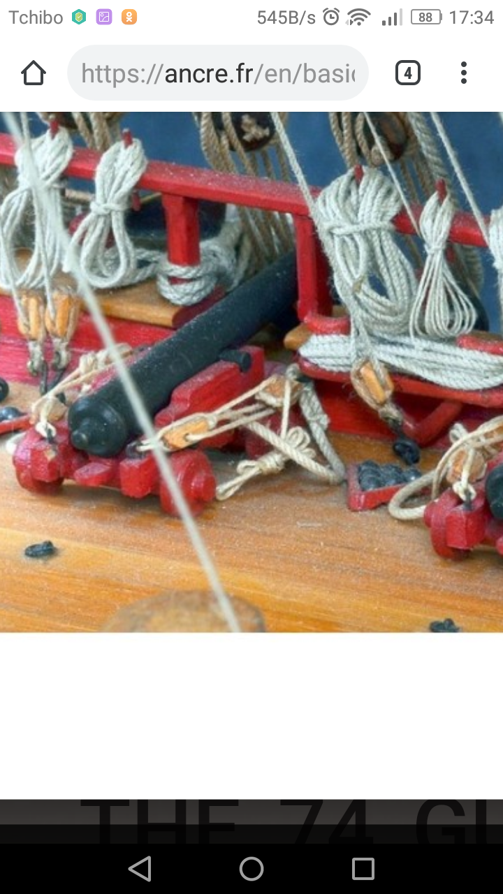
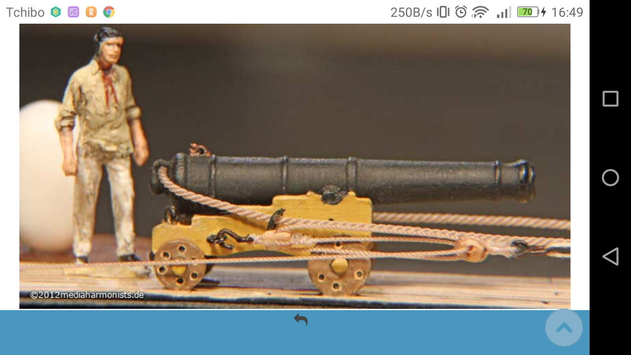
The dummy carriages do imitate a pulley,too?
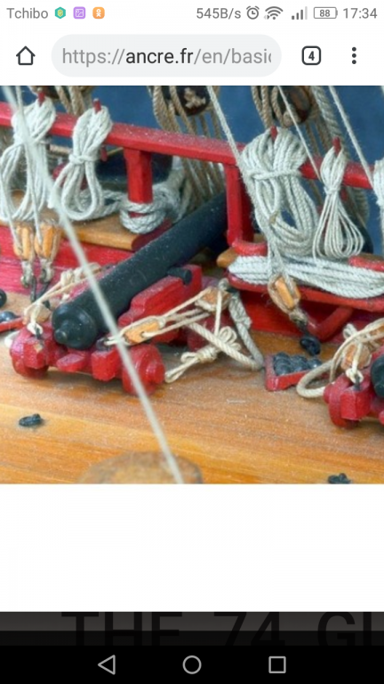
There is a good contrast between the darker red carriage and the natural wood blocks with the rounds of tan coloured rope.
Daniels gun carriages of his VICTORY

do still give me a heavy headache how to come to those results without dealing by rigging a pair of 1mm blocks under some of my neighbours hobby electron microscope...
As in the Ancre books not really a plenty of colour gides are to be found - does anybody know if the carriages wheels were completly painted or just oiled?
The tread of the wheels have to be in natural wood as the were "sanded" by rolling over the deck. (As not so easily to be seen on the picture above due to the difference between yellow carriage and wooden wheel running surface).
The wheels of HERMIONE have never/not often been in use?
In the coloured picture guide for the SAINT PHILIPPE marketing the tread may be used as to be seen eventually above - my eye sight is too bad for this picture.
Here they look pained red...
So I took some from mine and the tread is on this picture wooden - or this is wooden dust?
Due to this essay about weathering gun varriages wheels running surface/thread please do not tell me an "analogue nerd" - I'm told by my wife every 2nd day... 🙄
On the very end - as we all love these
Bodriout (from Le RENOMMEÉ, 1744) and
Closer to your SOLEIL ROYAL the Lemineur drawings at Le SAINT PHILIPPE 1693
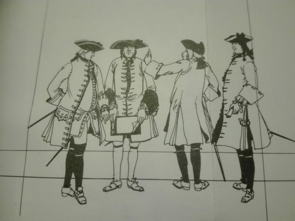
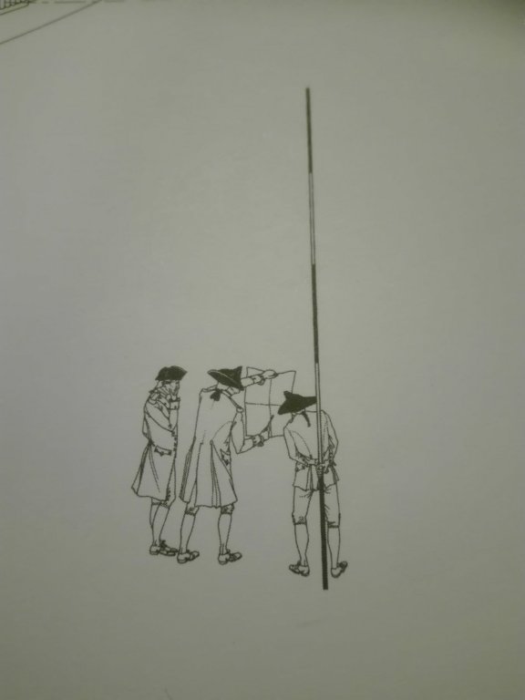
These beloved figues on the plan, you may like to add some Messieures as M.de Mesure Comte de Detailleé et Gabare
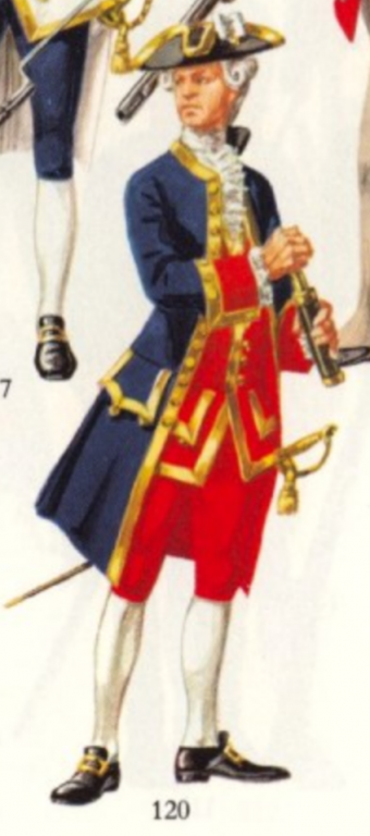
Here the royal French officiers dress of the XVIIIth century - perchance for 1689 too uniform?

- hexnut, EJ_L, CaptainSteve and 2 others
-
5
-
46 minutes ago, Hubac's Historian said:
Yes, I made a poor assumption; your shipyard is full! Colbert would be jealous!
I like your layout techniques. It’s a fine start to the drawing.
😅 "jealous"
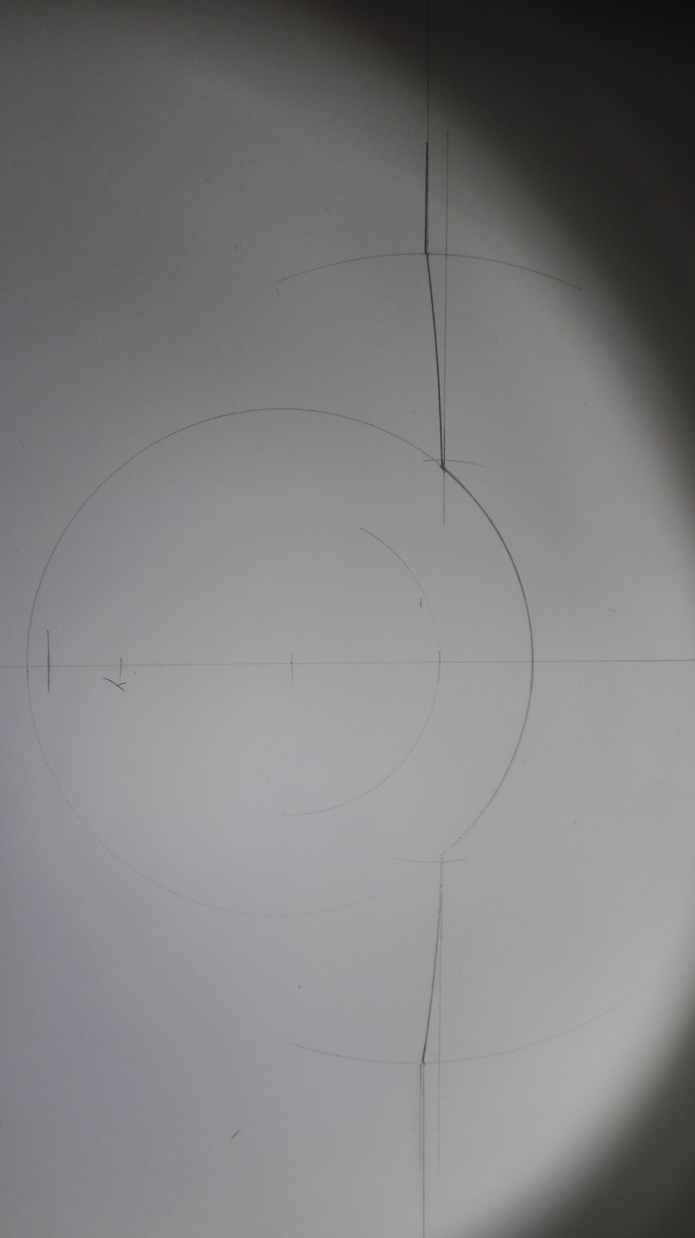
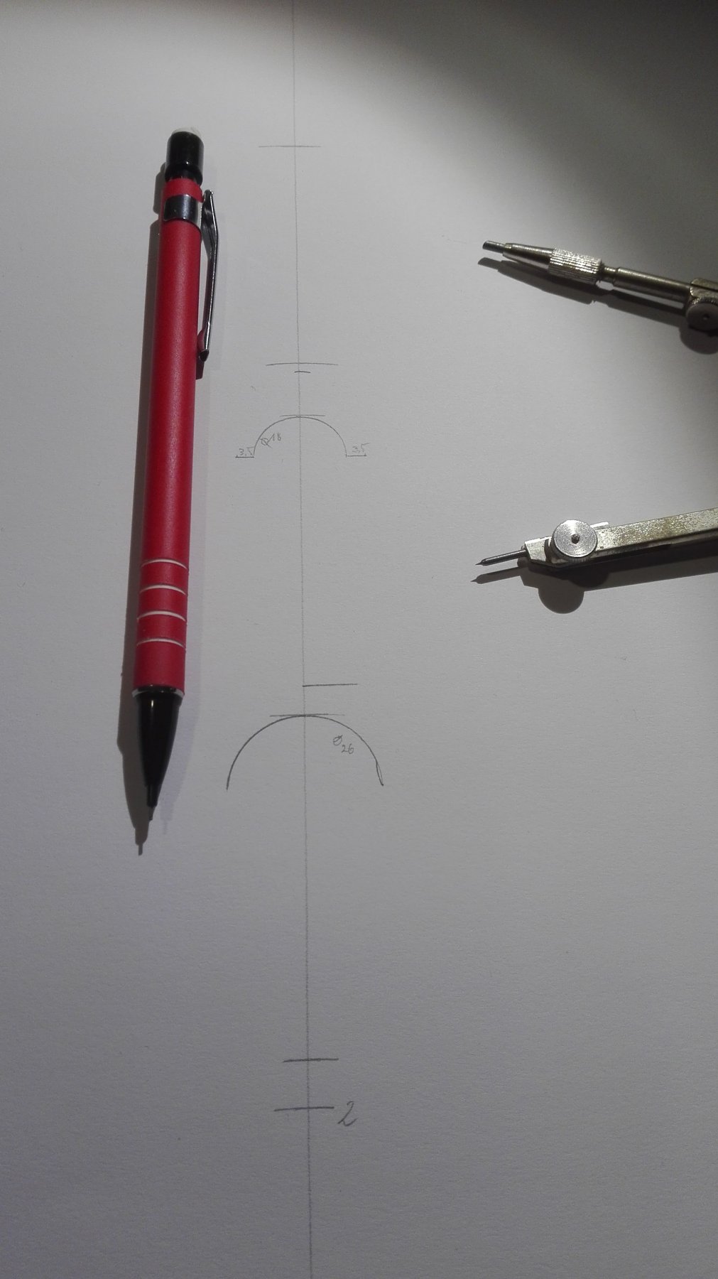
@Hubac's Historian okay marc, on the very beginning I have to look precisely for the middels and the needele of the pair of compasses are put into a hole I picked in with a very fine needle before to meet the lines crossing mostly exact. Hopefully this will exorcise errors, faults and inaccurates and keep them out of the pice of paper.
I'm not as far on the track as I hoped to be yesterday's night - but I'm qualitatively ON track that is most important.
"A good pice of craftsmanship always needs a craftsmans good pice of lifetime!"
is an old German saying (...told to be from
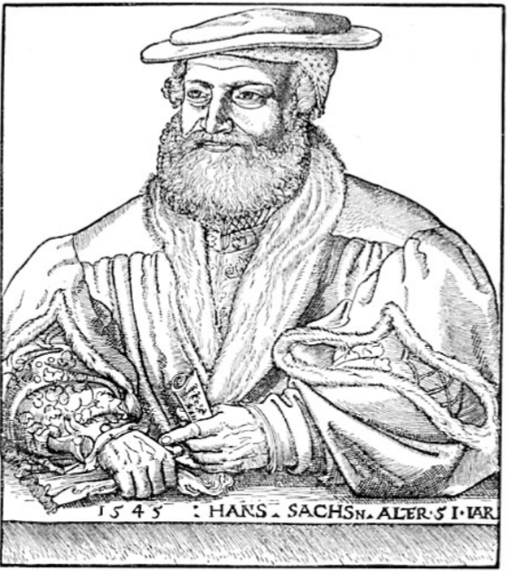
Hans Sachs [1494-1576])
- CaptainSteve, EJ_L, druxey and 1 other
-
4
-
@druxey thatis very helpfull, you give a good deal of additive knowledge - I cannot always press all the information into the artice/paragraph I wrote as I would overkill my readers with a mixture of allegorical, historical, geometric and additive technical information...
Due to these complex pile of circumstances your "butting in" is more - much more - than welcome to me!!!
Thank you very much!
- EJ_L, CaptainSteve, mtaylor and 1 other
-
4
-
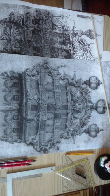
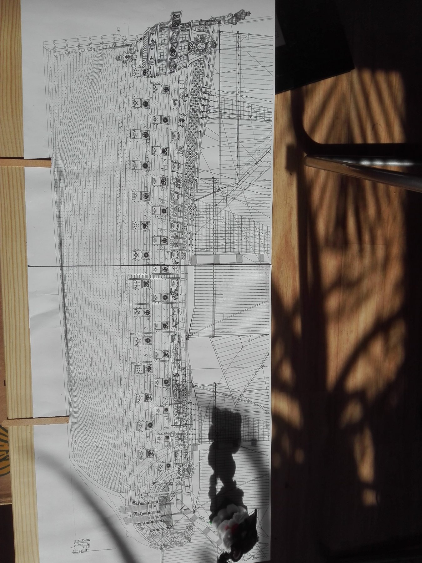
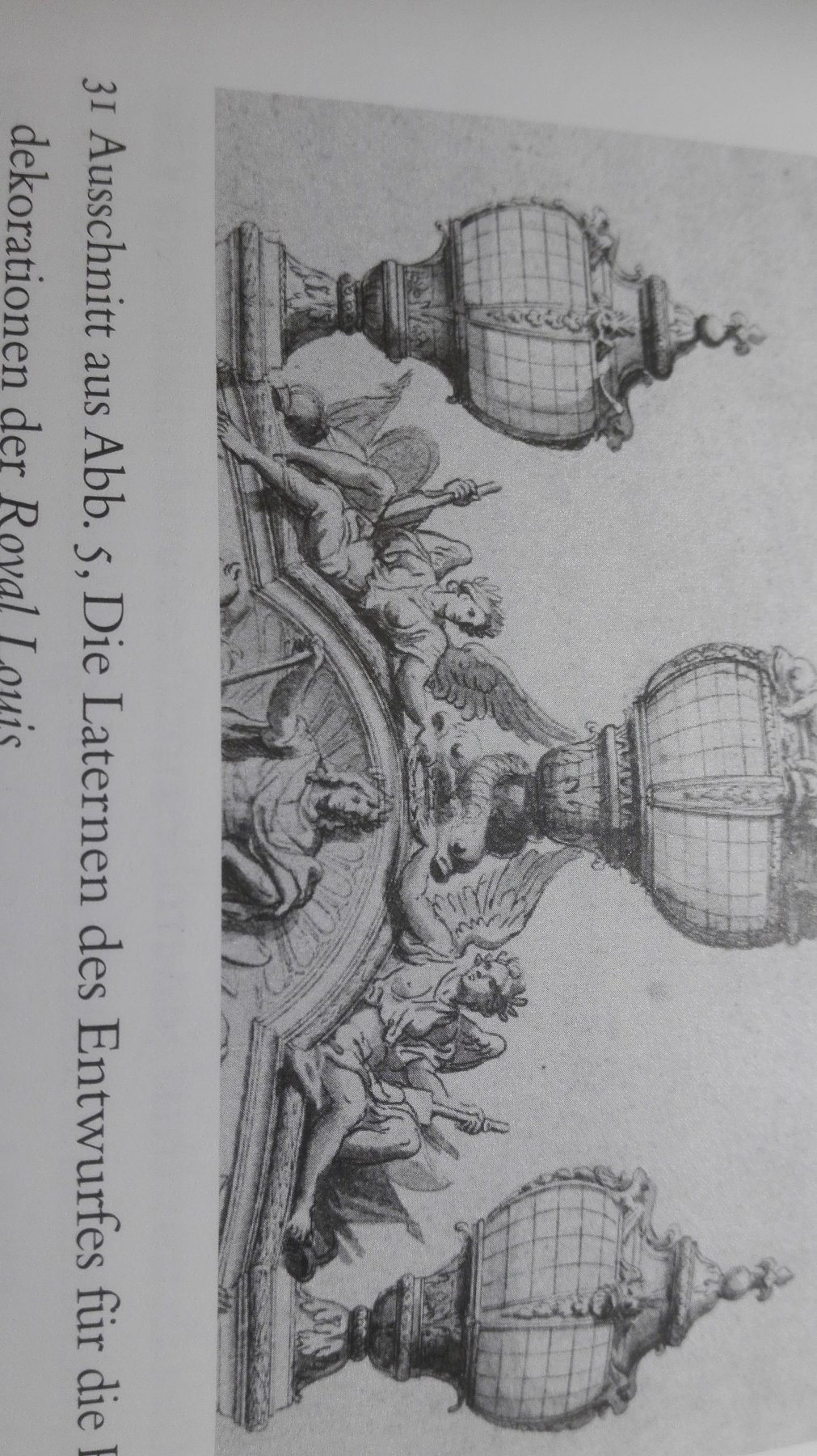
Okay, friends, this evening I've made some little progress.
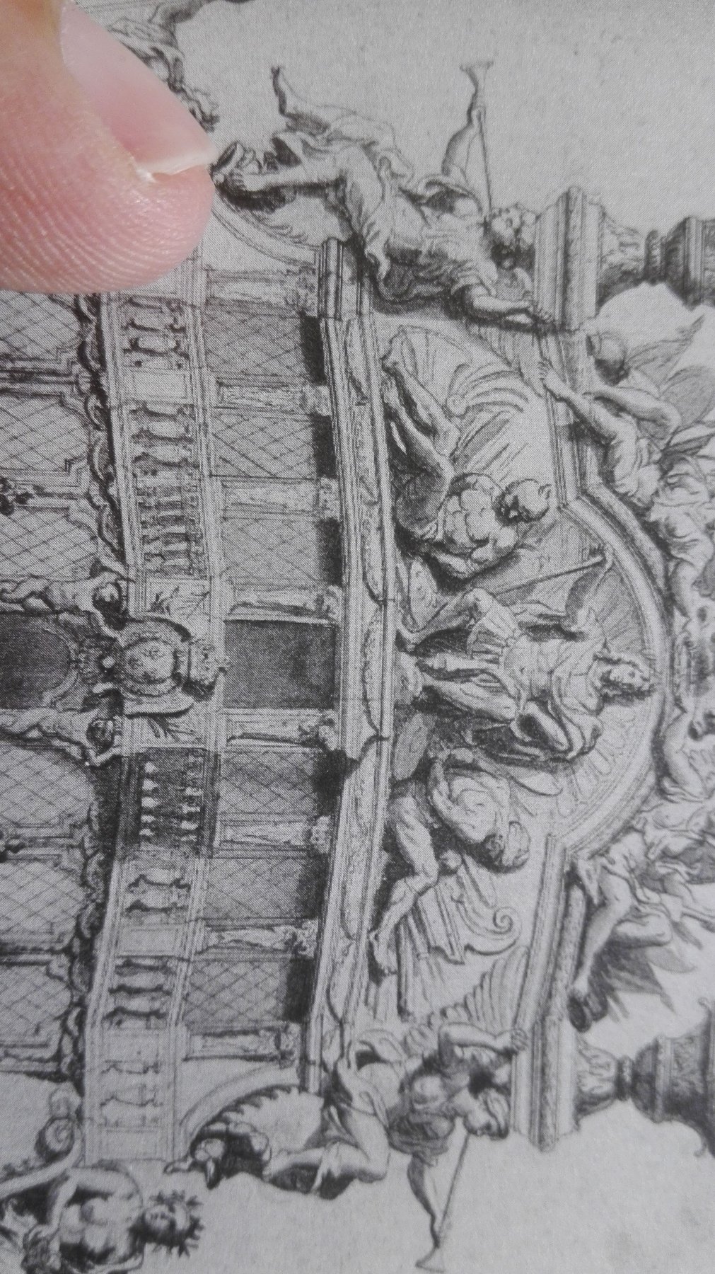
I decided to start with some part of the top end:
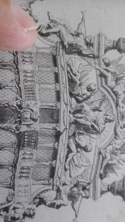
The Couronnement with Louis XIV. as Alexander the Great.

This is the line I was drawing last what is the inner line of the Couronnement as it lays on the
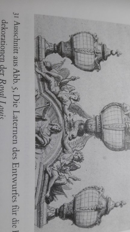
left side of the picture - so I'll have to add some thickness.

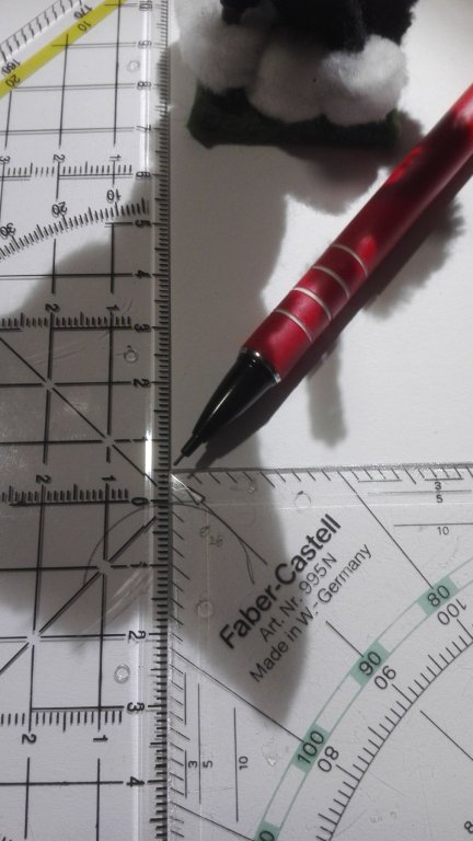
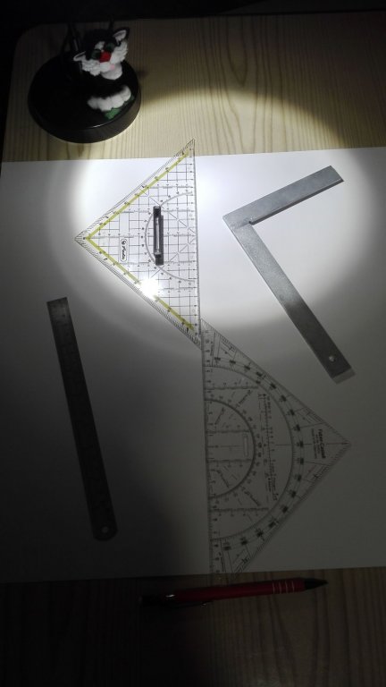
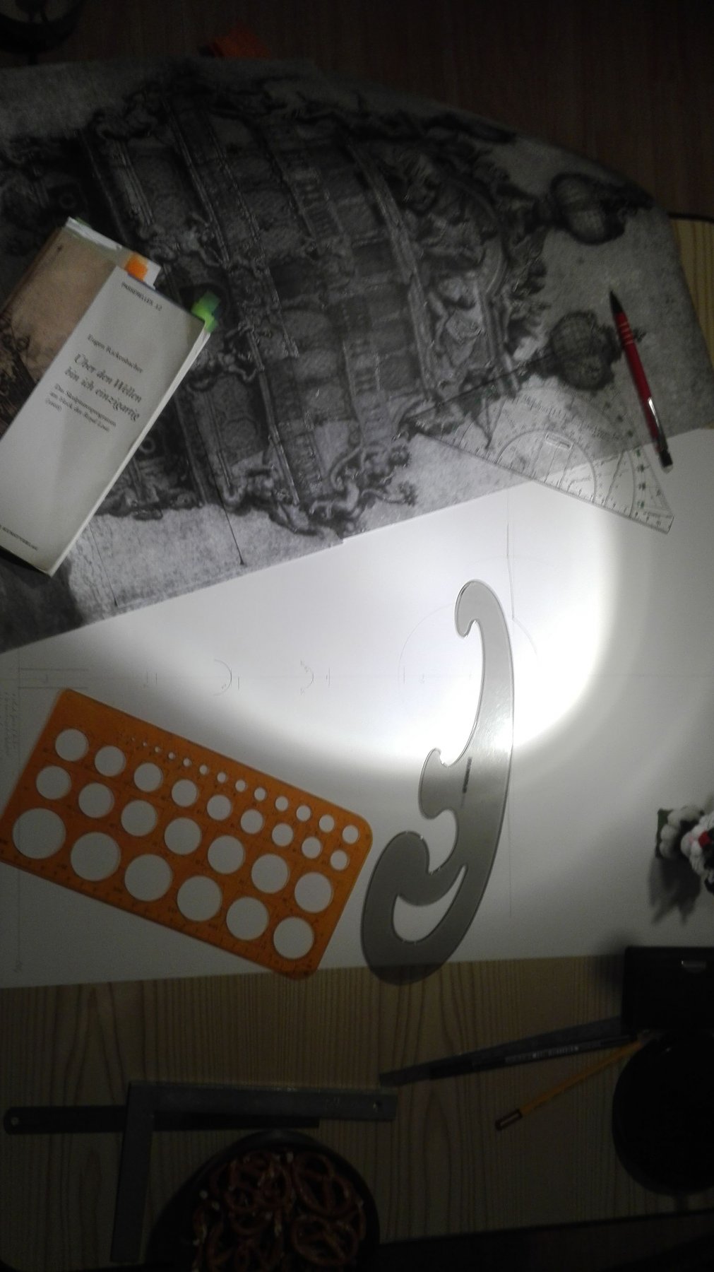
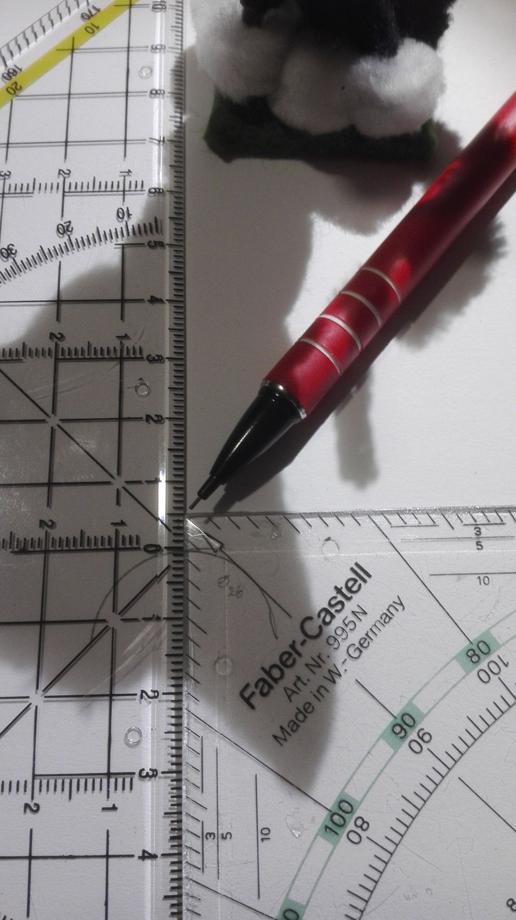
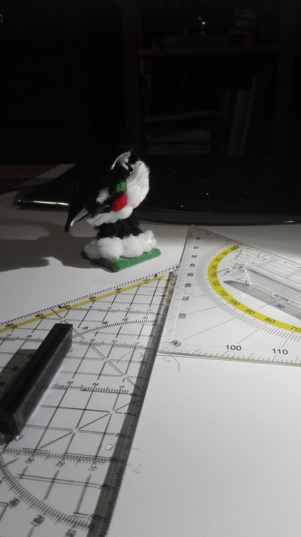
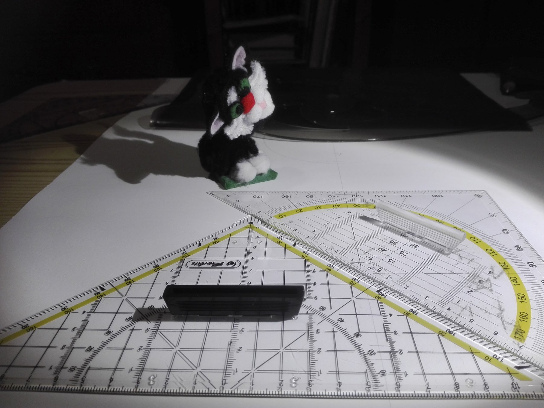
Here the used drawing materials. By these I was able to draw the upper planks underside of the doors.
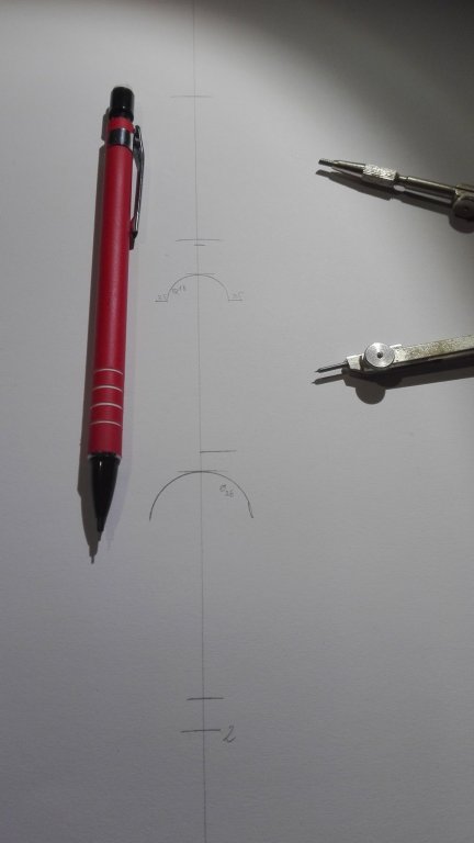
By mainly using a pair of compasses to transfer the dustances from the

Toulon drawing after LeBrun. And here you can see what is my way
(🤔...here you can see the drawing isn't mirrow symmetric...😲)
to get the diameter of the door's arc. The most important point is to stay as rectangular as possible
So I try to use my own way of drawing.

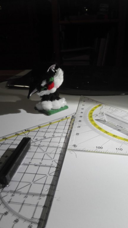
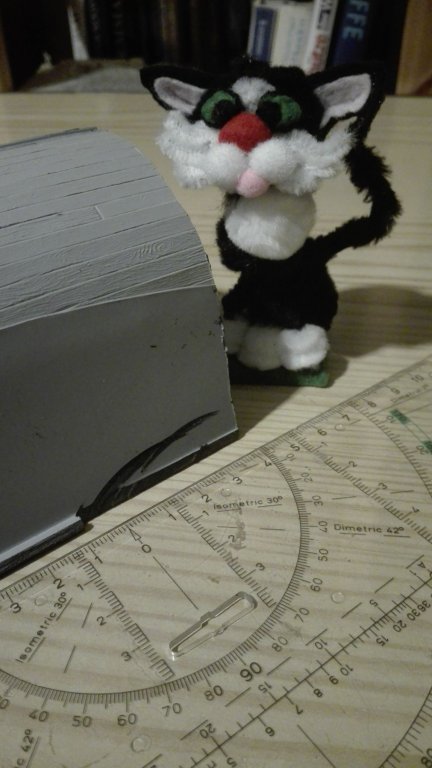
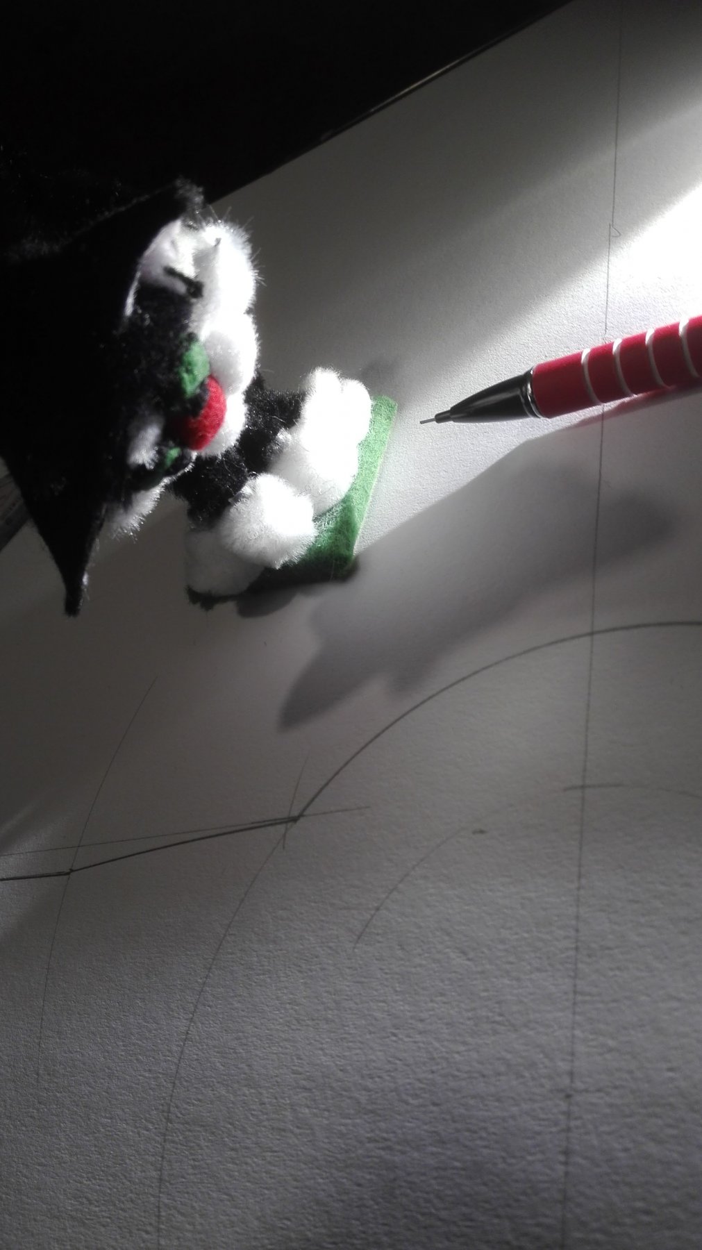
But my ships cat is still sceptical...

But I'm able
by this double tri angle trick to keep also rectangular
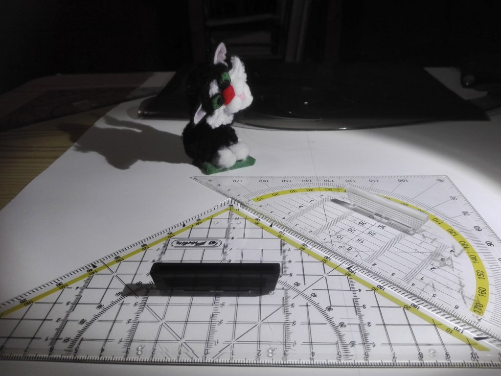
...as to keep lines parallel, too.
-
2 hours ago, Hubac's Historian said:
True, yes, but the scrap hull I sent you is missing the bow sections you would need.
Yes but I can act freely, freakly and freshly 😁
- Hubac's Historian, mtaylor, EJ_L and 1 other
-
4
-
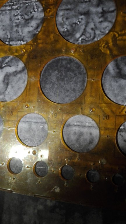
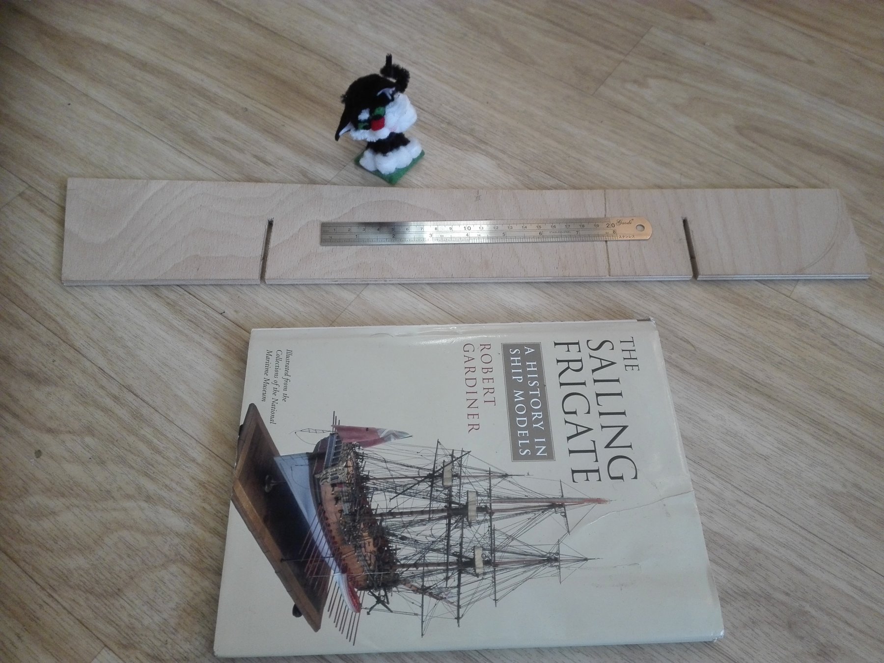
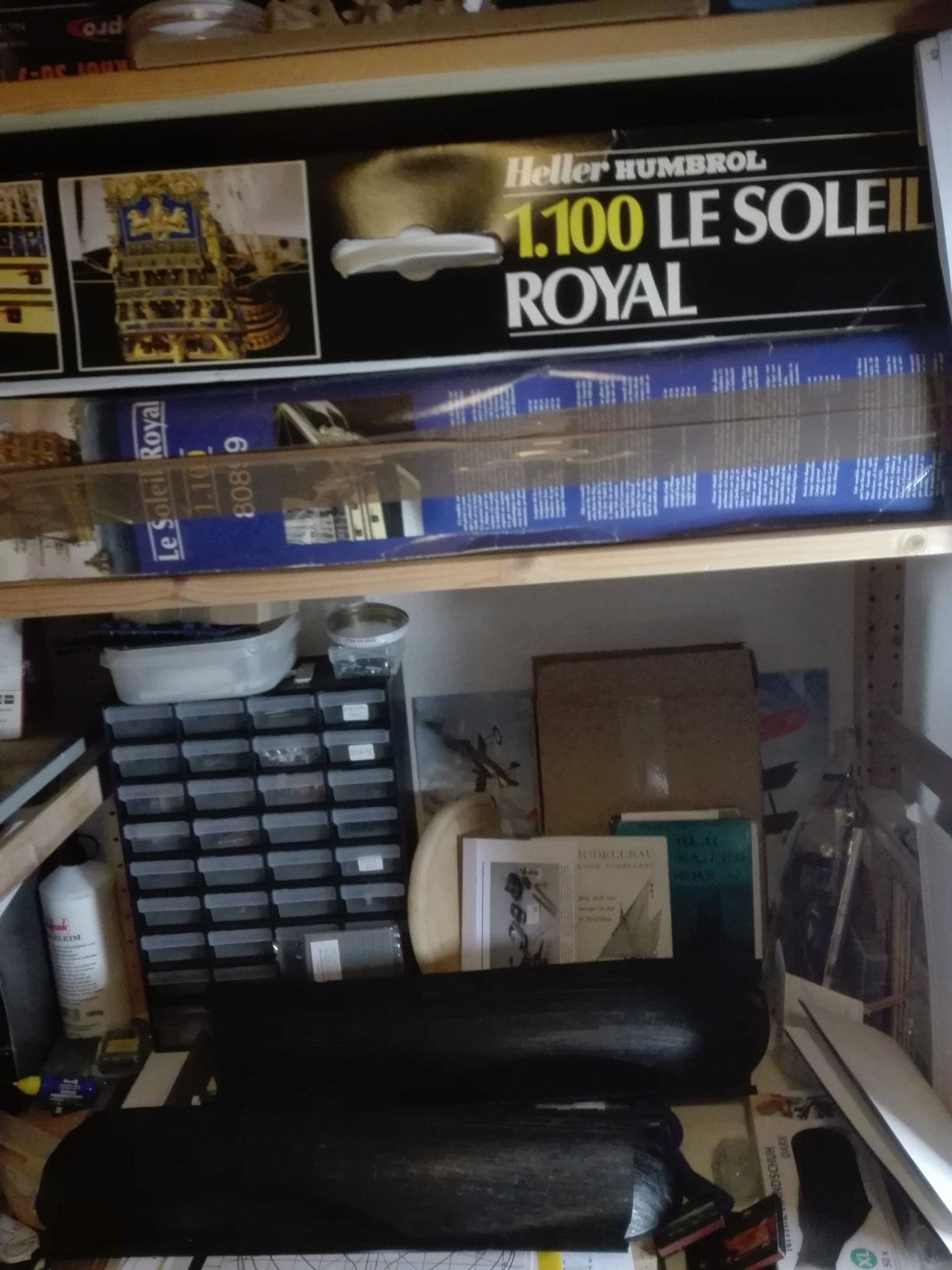
No, Marc, I am affraid, you missunderstood my post. I have got two complete kits and
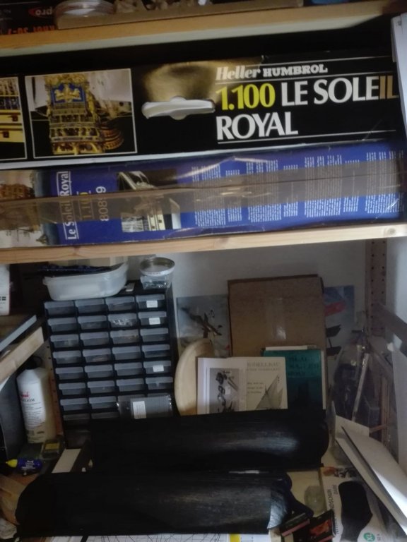
one complete hull [not in the picture: with upper deck, transom, side gallerys and galion (the hole light blue sprue)].
-
I have got two full kits and a hull in the Modelship yard so I can do the rebuild easily - more kits less cornflakes!
(TBC)
- mtaylor, EJ_L, Hubac's Historian and 1 other
-
4
-
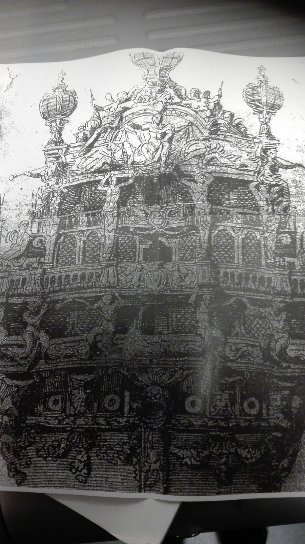
Hmmm there are between the
drawings differences more and more obvious...
I set a middelline in tthe drawing and interpolated a CWL
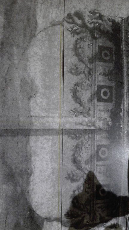
I think I'll take the right drawing as the guideline and integrate

the four Atlas figures in it as they are on any later Piget drawing also. I bends the transom taller. This due to the similarities to the other Piget sideviews.
I'm really unshure how to get some progress in a way I can reach it later when I'm buildung. So I'll have to redraw the full transom and can stop when the ships structure without decoration (doors/windows) is ready copy it and go onto the next step using the copies for construction. Does this sound like an idiot's idea?
I'm drawing on a 190g/m2 cardboard ficed on the camping table by Tesa. So I can remove it into safety folding the legs and hiding it beside the old bog oak cupboard.
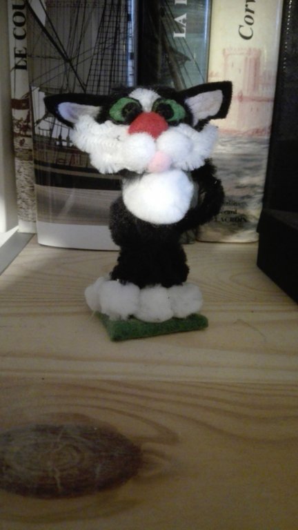 Shipcat is watching you!
- mtaylor, CaptainSteve, EJ_L and 2 others
-
5
-
Hello Phil,
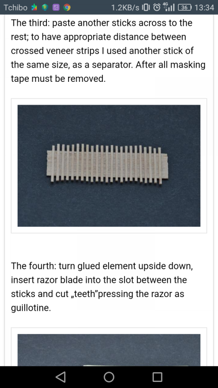
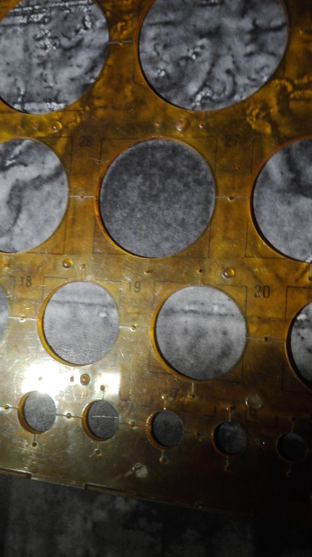
That is an amazing progress you did. To bash your kit please do not use the grit given to you in the kit - change it to the realistic one. Here a quick build guide (I didn't find the right link so far again.)
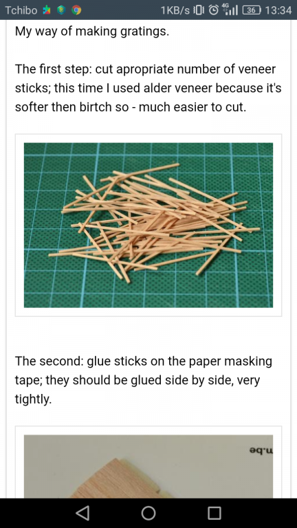
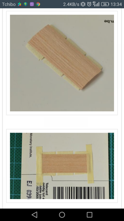
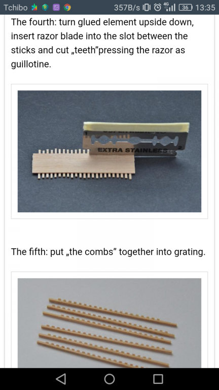
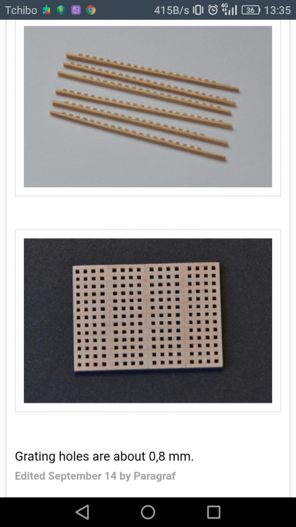
Hope this helps to avoid this typical too deep and unrealistic grits.
Over hete the original way to build.
And to make it perfect you can saw the plywood under the openings a bit away and add some dark brown paint to give some deep.
Hope you like it.
-
3 hours ago, mtaylor said:
As I understand it, French frigates of the 1700's only had a port lid on the very first port which didn't have a gun in place. That port was used for anchor handling. As for the rest of the ports, they used bucklers if the weather dictated such. There are some other details different in the frigates from the ships of the line.
The ports on the ships of the line with the nail heads. I wonder of the inner planking the carving was on was rather thin, more like a backing to hold the carving? Then the nails would be there to hold the backing on. I note that there's no drawing showing how the carving was affixed to the port. Come to think of it, I've never seen any details on how any carvings were affixed to the hull.
But on the oilpainting it is clearly visable that there are lids above any gunport... 😳
-
11 minutes ago, Hubac's Historian said:
Overall, my width increase amounts to a heavy 1/2”, almost 9/16”. That is what was required to add in the missing sixth stern light.
(...)
🤔...this would be some 12mm - I do add something around 5mm less than 1/4".
Lets see towards where the journey leads me...
-
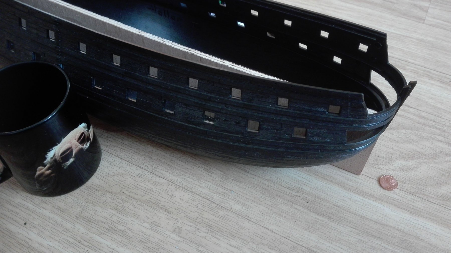
Exactly the safe guard was
annoyingly colliding with the hull 😲
-
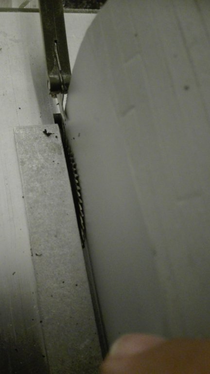
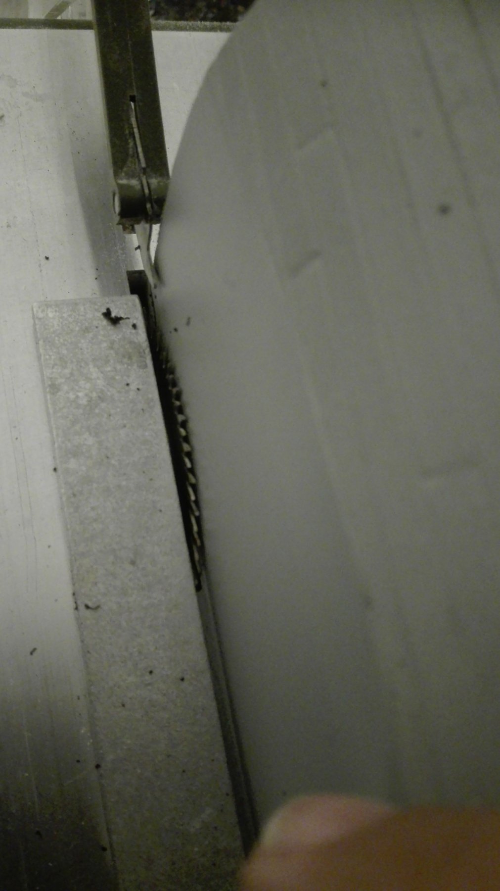
Dear Marc, thank for this great lesson in rebuilding a Heller hull. You have been able to inspire me and gave me the courage to try myself out at the Proxxon mini table saw.
But I was after some 50mm stopped by the osh parts of the saw... so I'll have to remove this before getting further progress. But I won 5mm of width in the hull. How much you did add to your hull at all?
As I'llhave to replank the hull at the very end over all I must not be bothered about the puttying&sanding action at all.
- EJ_L, mtaylor and CaptainSteve
-
3


SAINT PHILIPPE 1693 by Heinrich der Seefahrer - Heller - 1:92 - converted from Soleil Royale kit
in - Kit build logs for subjects built from 1501 - 1750
Posted · Edited by Heinrich der Seefahrer
Added answer
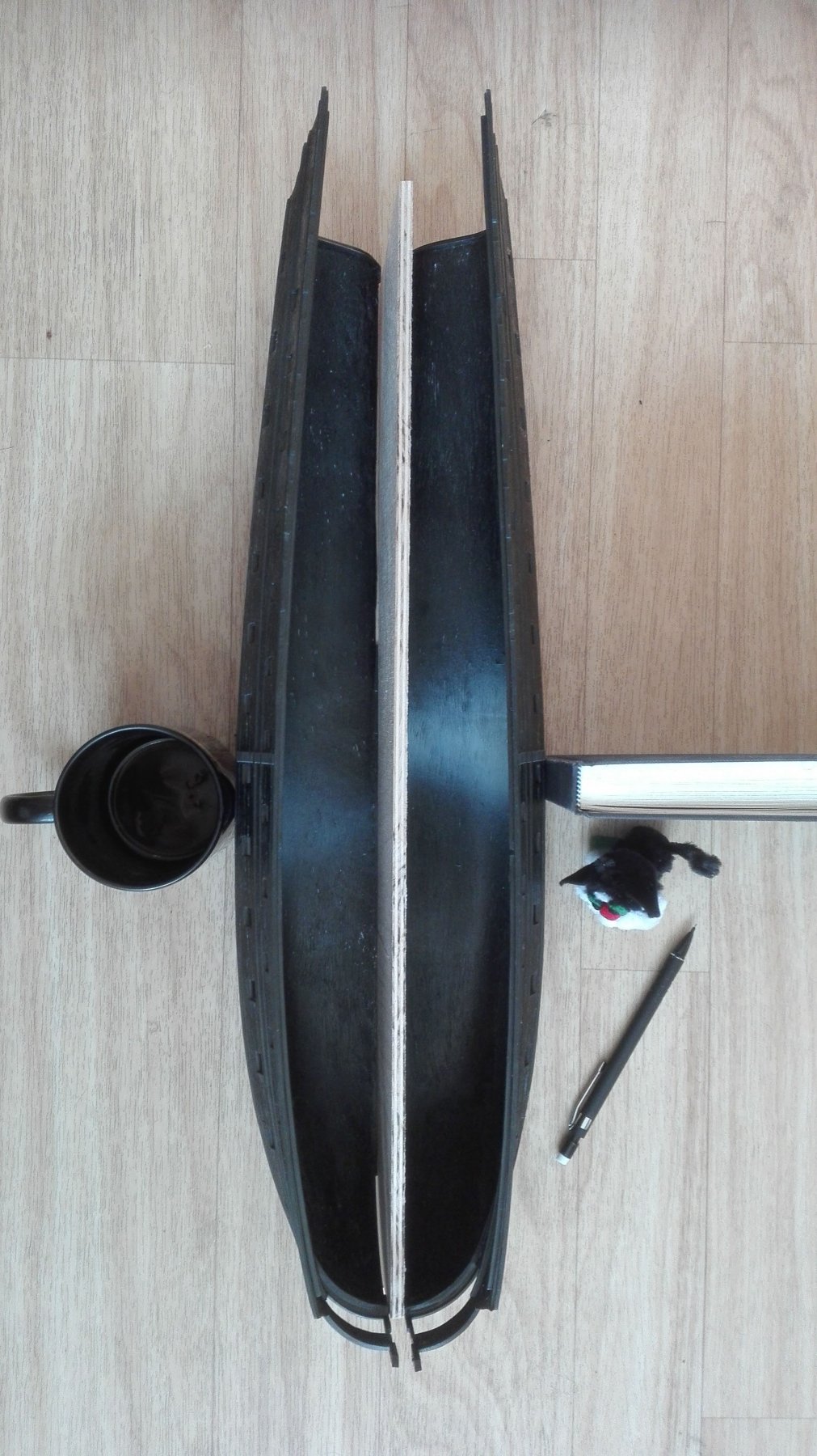
Thanks a lot, Marc, for the trick with these hawser pieces. As they are
wrong - right is the rigth side!
they do give stability for the trimming job.
I'm not really sure how to build the keel stem and stern from wood or plastic sheet as I would only have to engrave the
complex parts onto it.
As the rest of the galeon will be a really heavy amount of work...
and I get the feeling to come closer and closer to the point where the time safing aspect of the "abuse" of the kit for bashing it starts crossing the graph of a scratch-built-build.
What gets completely clear when you look on the triangular part covering the stem, hull and the begin of the galeon - that will be a tricky pice of work.
But to answer your question honesty:
So I do think of a mixture wood for the keel and stern as it is cheaper in the needed long pieces than plastic and plastic for the stem and galion as it is easier to work on by engraving.
KEEP CALM
AND
BUILD MODELSHIPS