
Heinrich der Seefahrer
-
Posts
533 -
Joined
-
Last visited
Content Type
Profiles
Forums
Gallery
Events
Everything posted by Heinrich der Seefahrer
-
 And due to this I invented the "rectangular to the formers line" in German Purple: And made shure it is rectangular: Next step is the adding of the grooves for the 6mm thickness of the bulkheads. Edit - ready: Next problem the stem's round and the high poop deck.

-
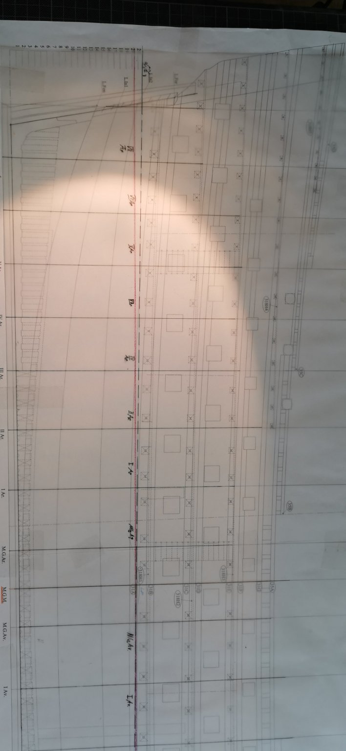
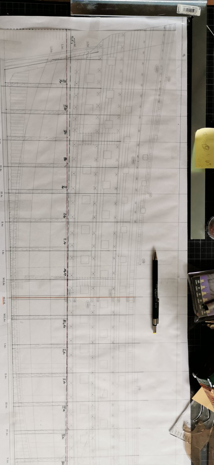
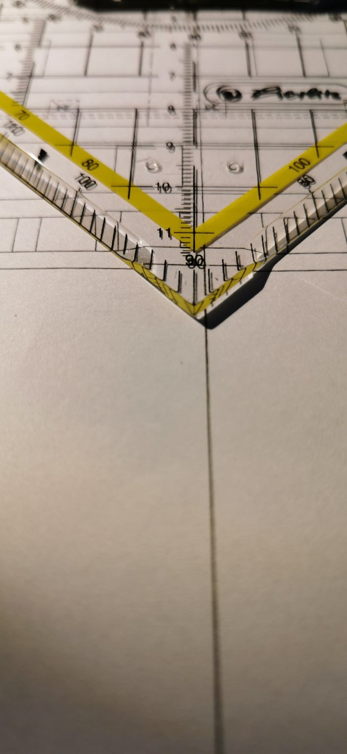
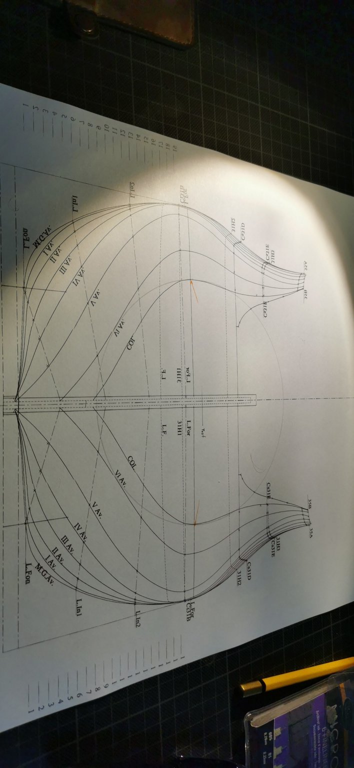
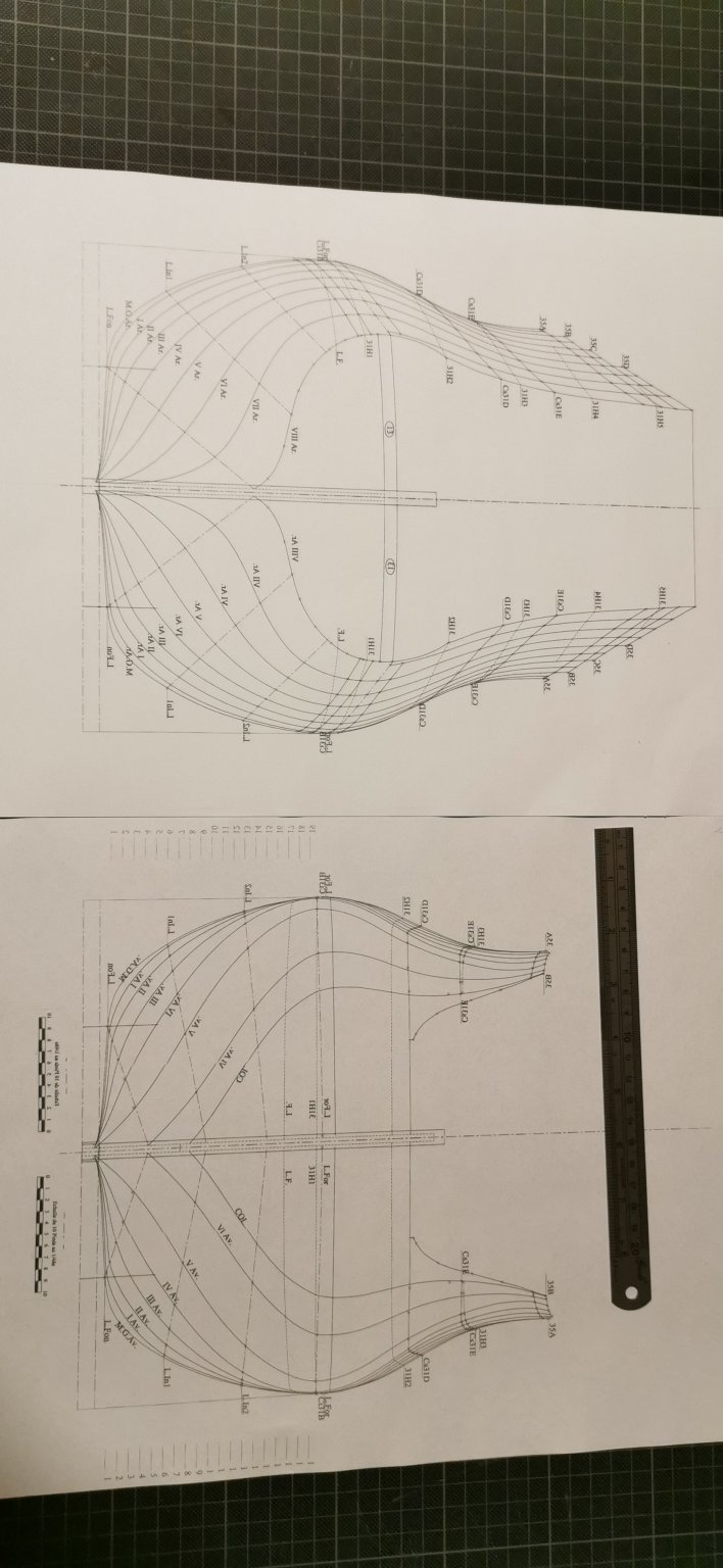
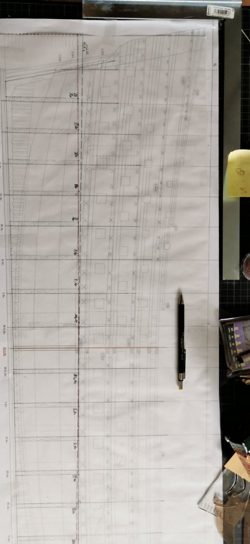
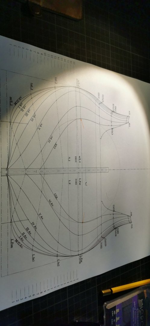
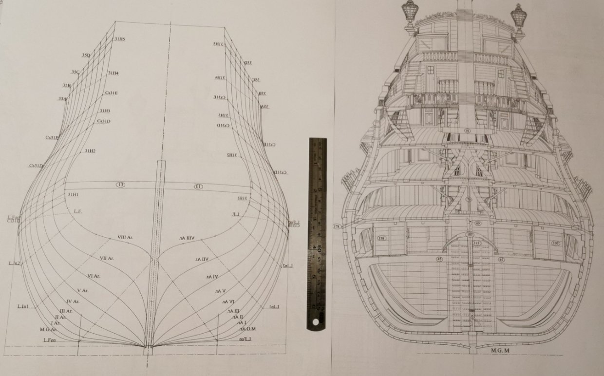
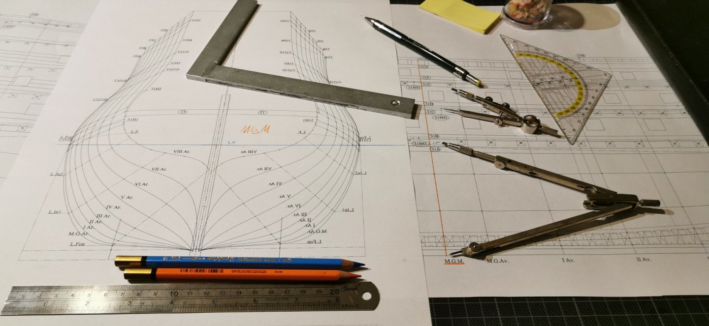
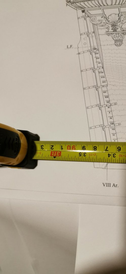
Hello friends, yes I am very very thankful for your both helpful advices and I am documenting the problems in here for all those that want to build the SP later on. It was absoloutly clear to me that SAINT PHILIPPE would be an enormous project of great difficulty. But I decided to start with her as the next ship shall be ROYAL LOUIS 1667 or DAUPHIN ROYAL 1668 so what I want is the luxurouriourious overwhelming decoration of the Sunking's 1st Navy I have to admit. 🤗 So I will have to go with the plan and cut mit notches on the middelplate in an angel of 89.1° - that sounds awful. But we are where we are! And so fixing points for the decks must be stem and stern and an self made grid about the plan. Bad news are piling upto each other... ...and now I am in real trubble because Plate 1 has an enormous problem: The L.F./CWL and the MGM-former is NOT RECTANGULAR! So I checked the rest of the AR and Av lines and NOT ONE of them is rectangular to the L.F./CWL!!! Okay this may be problem due to the reduced copy so I contrachecked the 1/48 original Ancre plan: And it also nor of the formers is rectangular to the L.F. - either to the keel. The only paralellity is given by the formers to each other-the formers are parallel to each other. I also checked the original plan in 1/48 to check for copying faults or errors... The angle L.F./MGM is in all Plates about 89.1° - So we are all that we do build the SP are in real trouble, aren't we? I also checked the original plan by Ancre on the Sideview and cut on Plate 34, Plate 17, Plate33 and got the same result of 0. 9° missleaded rectanglarity... Thanks for the patience with my curved way towards the model. P. S. : So it is totally clear that Ancre is going to kill its world wild reputation by publishing shifted plans of L'HERMOINE and SAINT PHILIPPE. I thought about buying their newest monographies of the Galley FLEUR DE LYS. But as the printouts come from the same publisher I am VERY VERY DOUBTFUL to belief that G. Delacroix's work isn't "infected'' by this problems, too. I thought about the new LOUISE as a present for a friend of mine - but now not in any way. I may buy the old hand drawn planes of the founders Berti and Boudriot but no new productions. Sorry Ancre but I am fed up with this way of working with your customer's expectations.

-
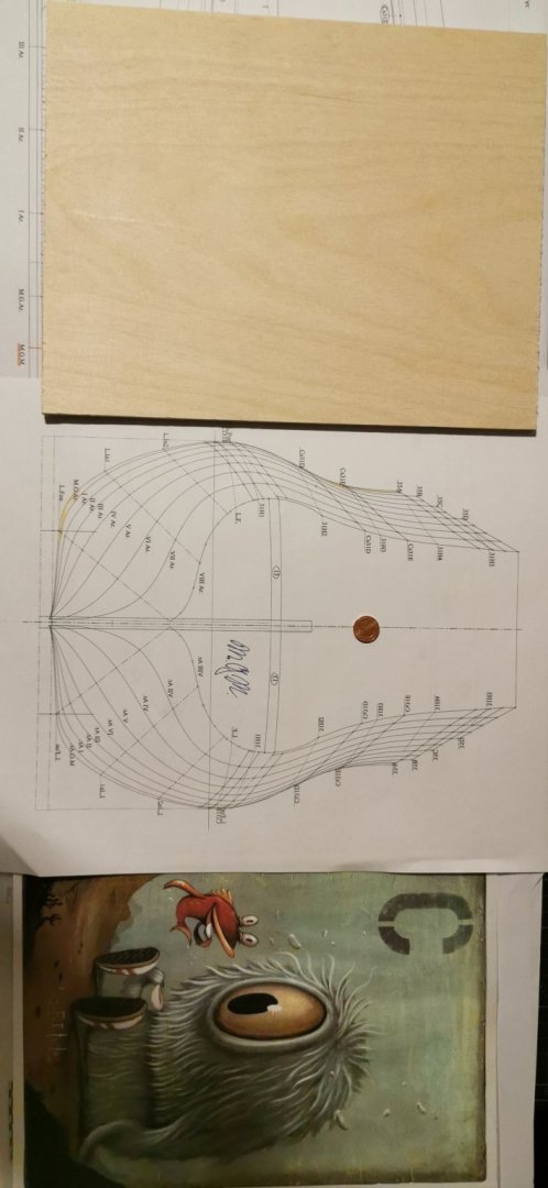
I looks as is in here a CADproblem... Here is shown that L.F.(blue) and MGM-former (orange) are rectangular. The layer of projection changed between the L.F. and the NOT paralell keel layer... What gives some disgusting differences. The 1° angle between L.F. and keel layer may explain the shifted former lines in the deck drawings. So I can only use the CL orientated drawings and the former orientated drawings - if these were placed right!!! This is the question...whether tis nobler in mind... To suffer the sings and arrows of outrages fortune... Or to buy some 250x240mm and 300x240mm plywood and by apoising end them and drink some tea under sea. I got my ordered wood for the model today and a drawing "tea for two".
-
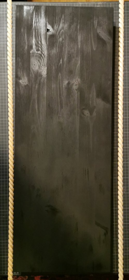
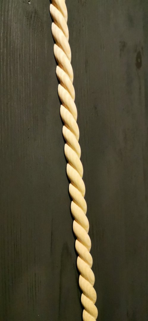
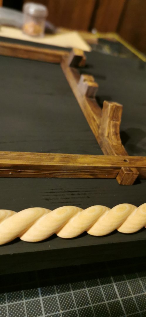
Okay I worked on the big sister mostly but did not forgot my building place here. So today I bought a board of pine and some craved ropes, so both will fit unter the stand. 😁 "Call me Captain Blackboard!" 😁 Not a plenty of news but a bit of progress is still progress... So I stayed loyal to my motto also today: "Do 1/2h of modelshipbuilding every day and you can't keep your progress away!" I have to admit I do love this contrast: Here my strange idea of mixing blacked wood, natural wood and imitated wood becomes reality : What is your opinion - about adding any further finish to any of the t(h)ree ingredients???
- 244 replies
-
- 4
-

-
- heller
- soleil royal
- (and 1 more)
-
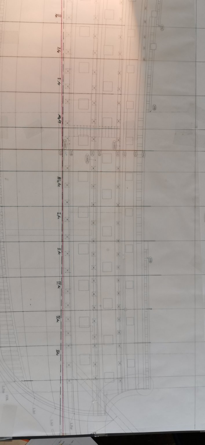
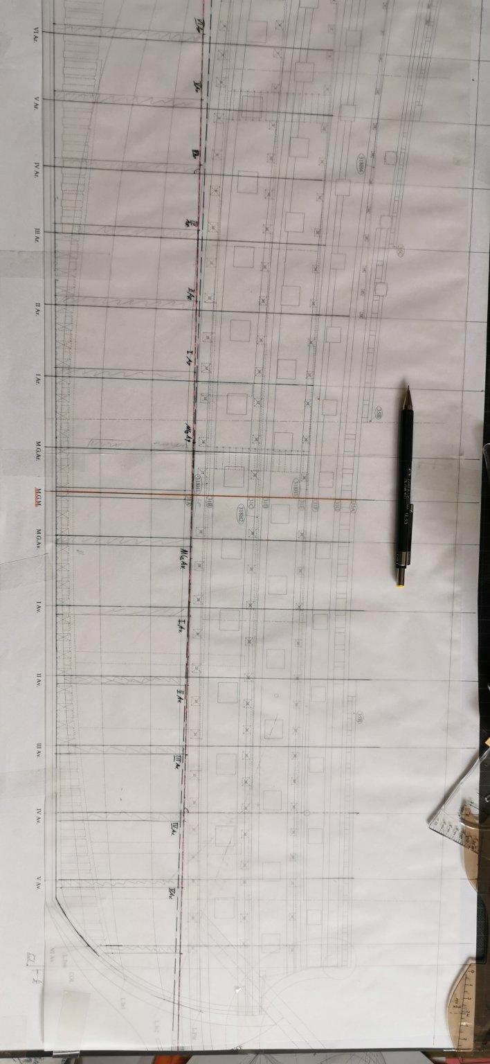
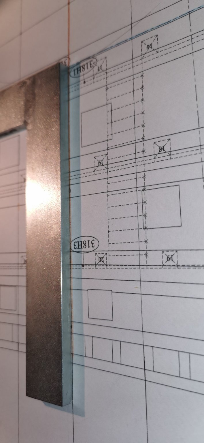
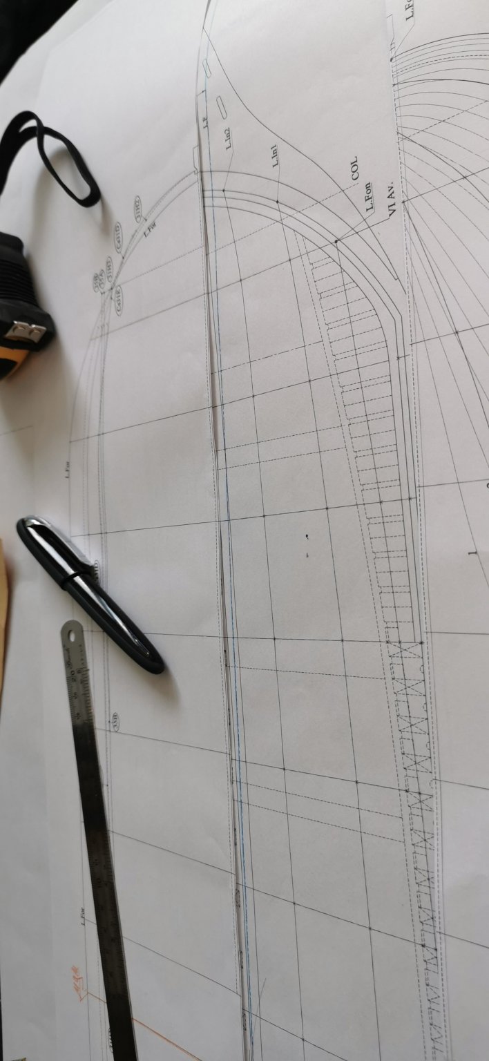
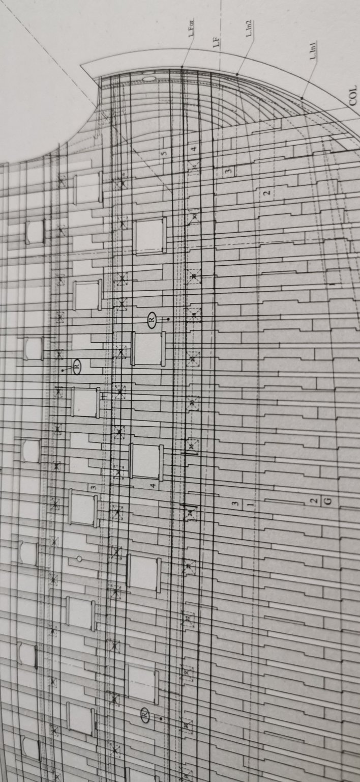
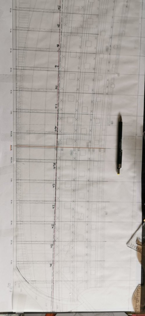
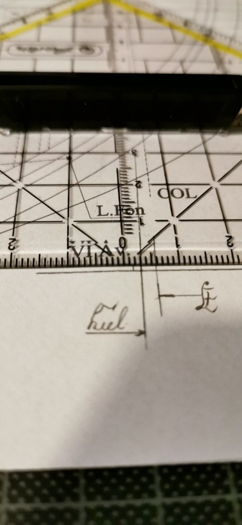
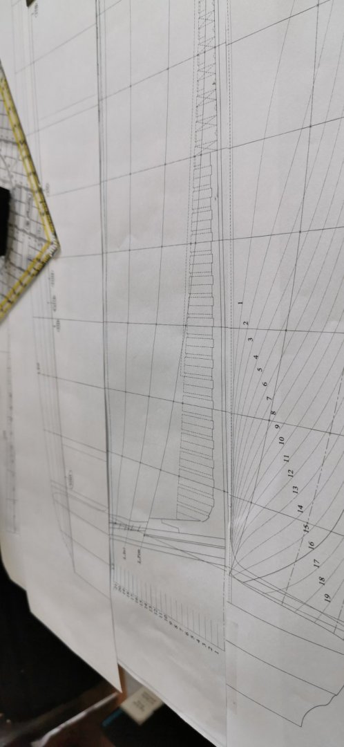
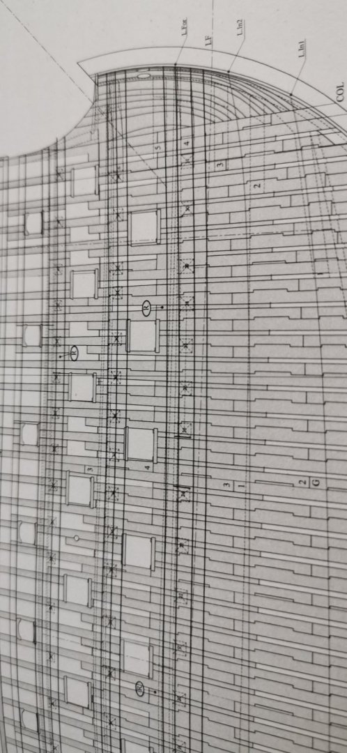
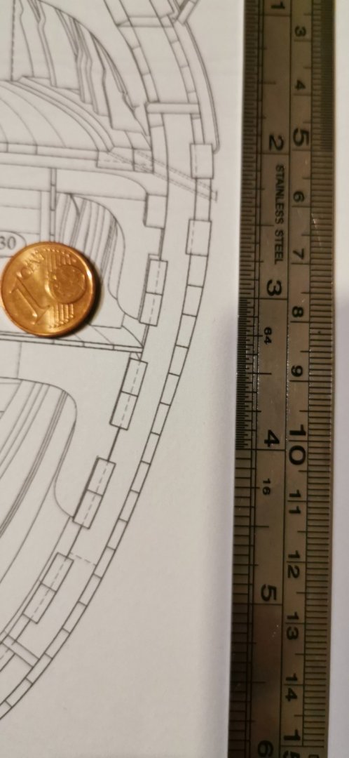
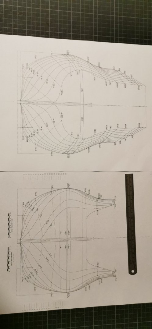
Till now everything was fine, but it does appear the Fault-Monster: I compared the plate 2, waterline, with the plate 1 the side view cut my water lines at the CL I placed it along the L. F. - so the former lines must fit. But they doesn't do this! The stem isn't in one place at all. The COL (first line behind the stem) is displaced in the waterline plan about 4mm much more than 1/4 of a meter in the original ship! My basic idea was to use the Waterline to cut spacers between the bulkheads AND do shape the lines of the ship in one step. Nearly a meeting of two lines... The MGAr and MGAv are nerrly mirrowed to the MGM with hardly a distance error. "Go back to the drawings and identify the very right "placeiation" for the bulkheads!"

-
B. T. W. : A good made sharp copy photograph in 1:1 of this Puget drawing was around $90 last summer.
- 2,699 replies
-
- 2
-
-
- heller
- soleil royal
- (and 9 more)
-
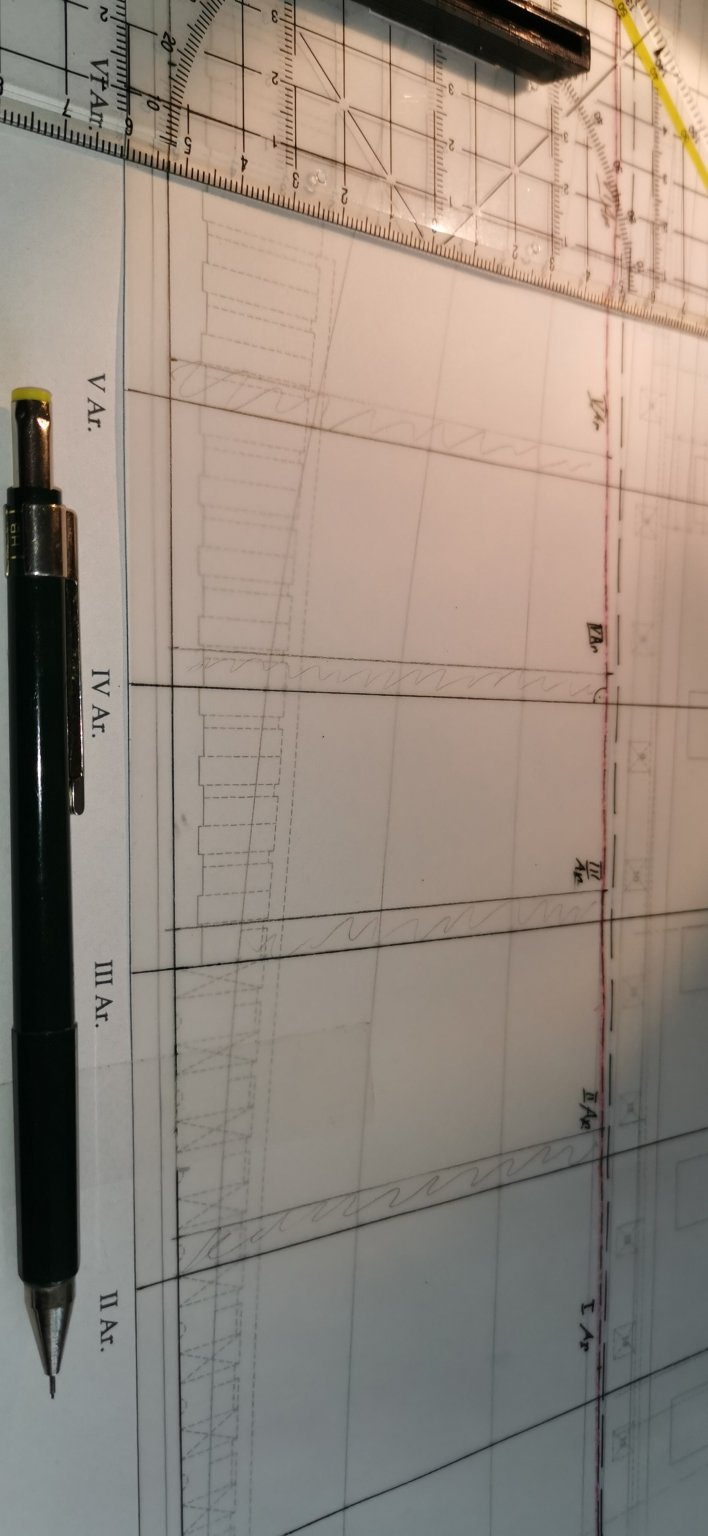
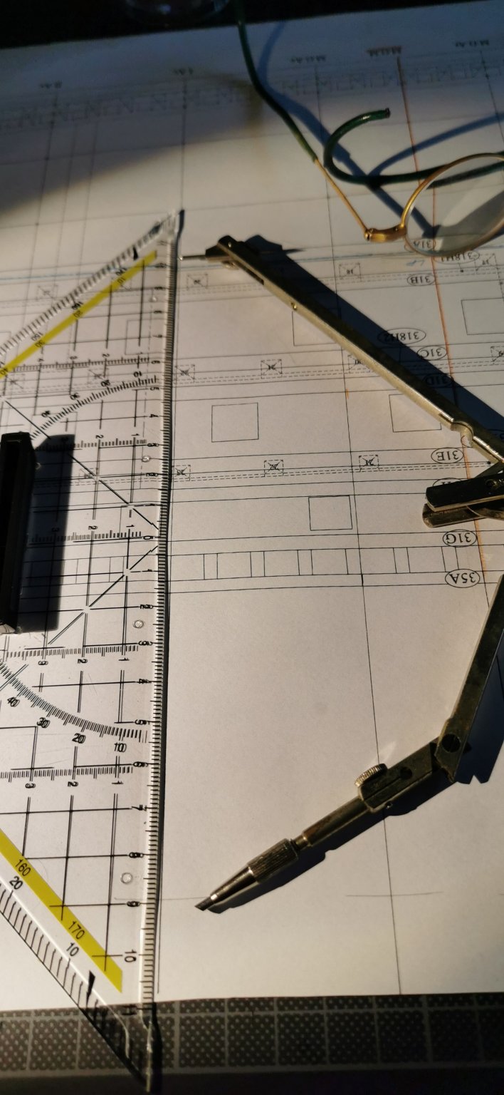
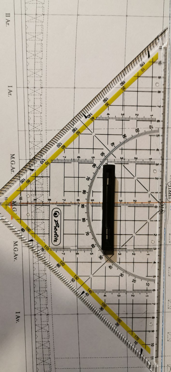
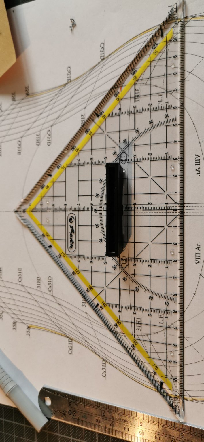
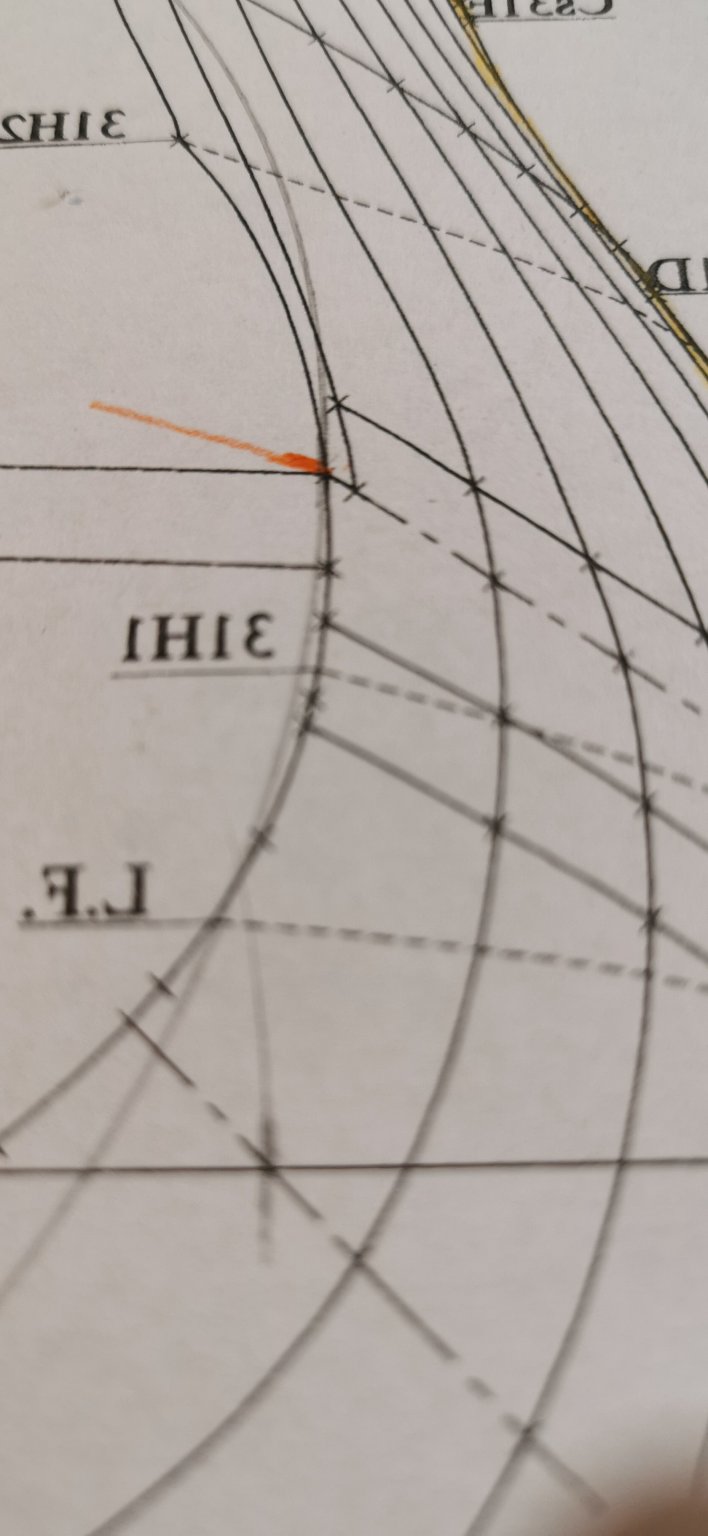
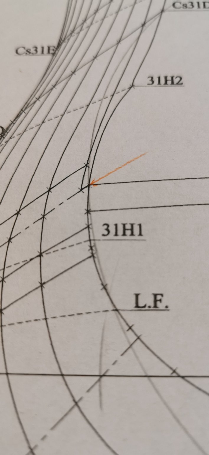
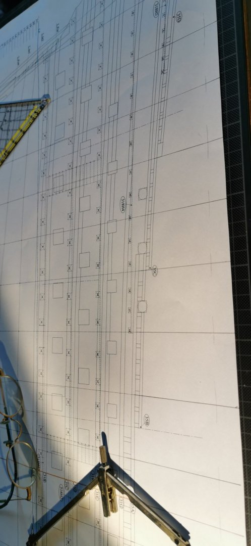
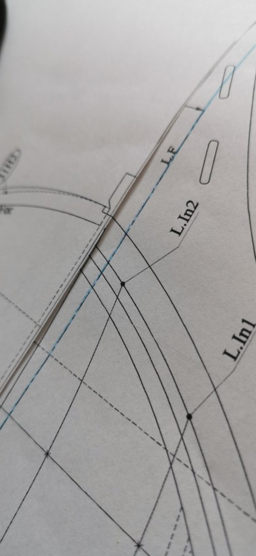
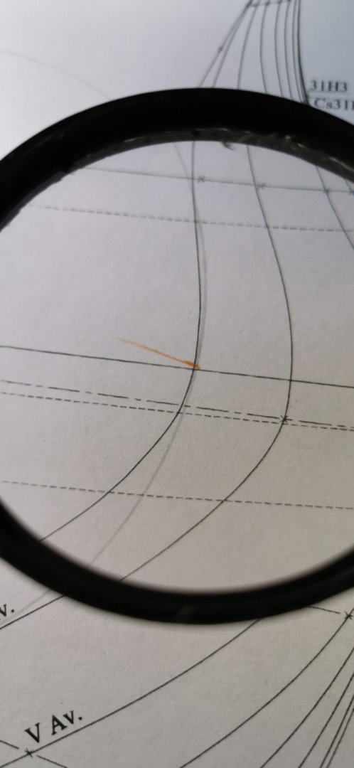
Now the very same for the Av.-lines: The chicking with the pair of compasses schows an light incorrect measurement about 1/10 of a millimeter on the backboard side: The portside picture does not load up so I cannot show you how exactly the radii meets the printed line. My problem for tomorrow is to name the top ends of the forecasted bulkheads right as the mix up the do seperate but can I count them and address them in this simple way? This question is for the Ar. poopdeck lines certainly, too. Is anybody who could help me? I want to copy every bulkhead's former before starting the cutting out on paper.

-
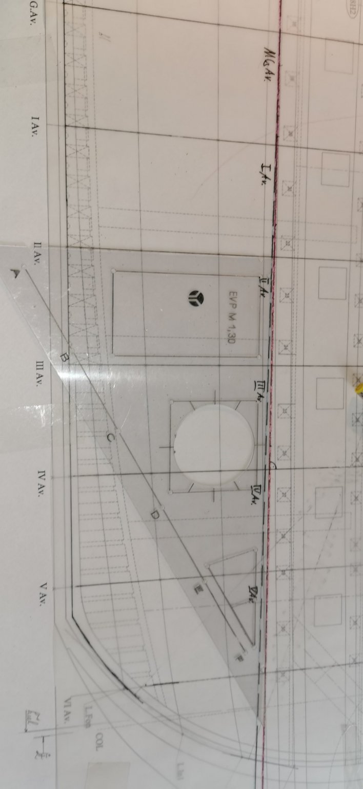
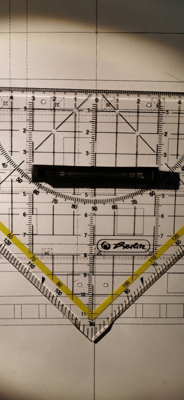
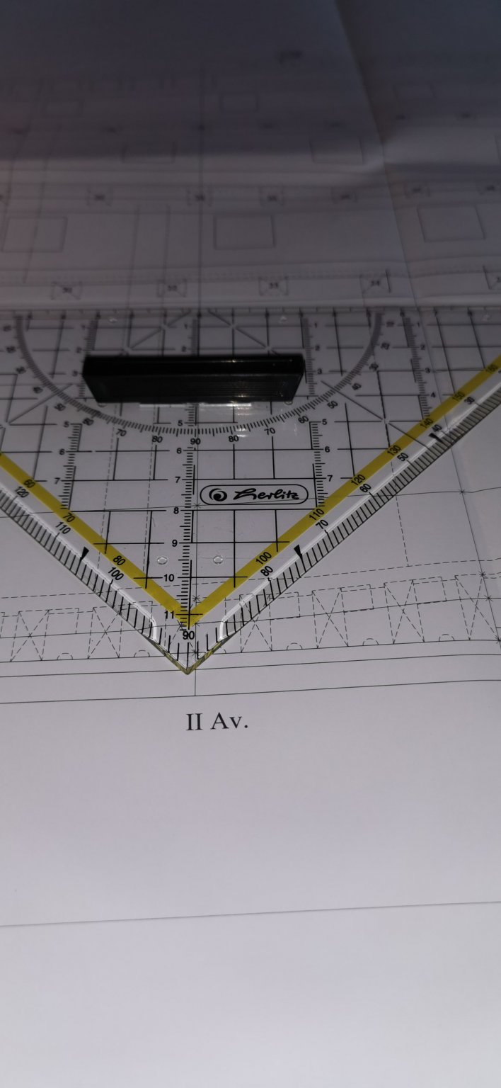
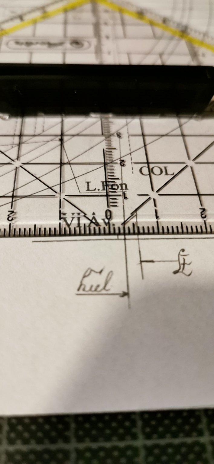
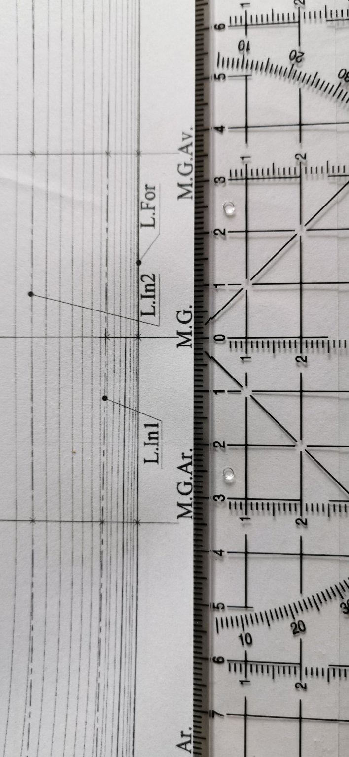
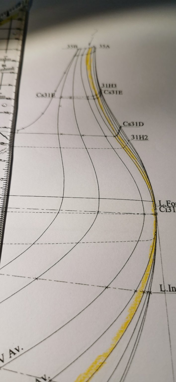
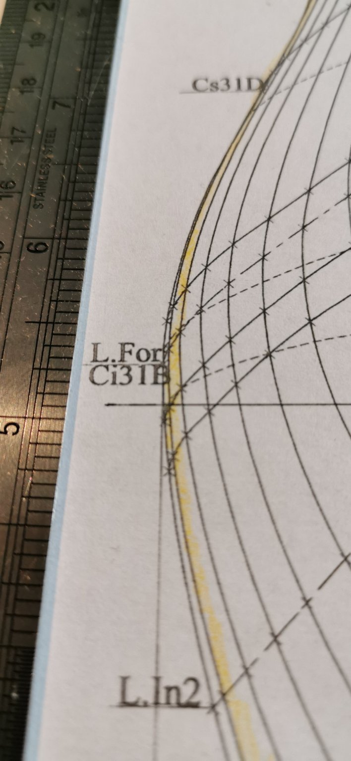
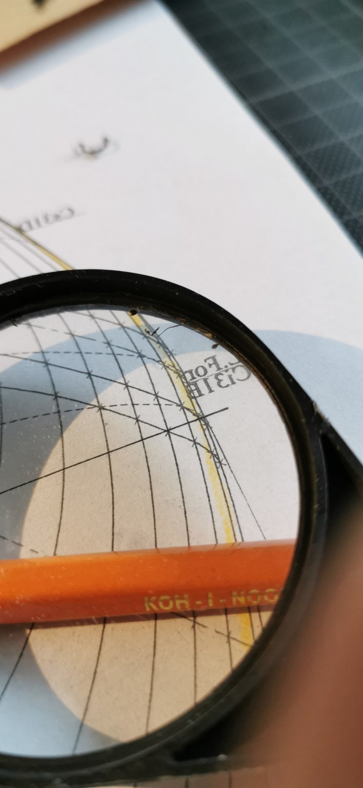
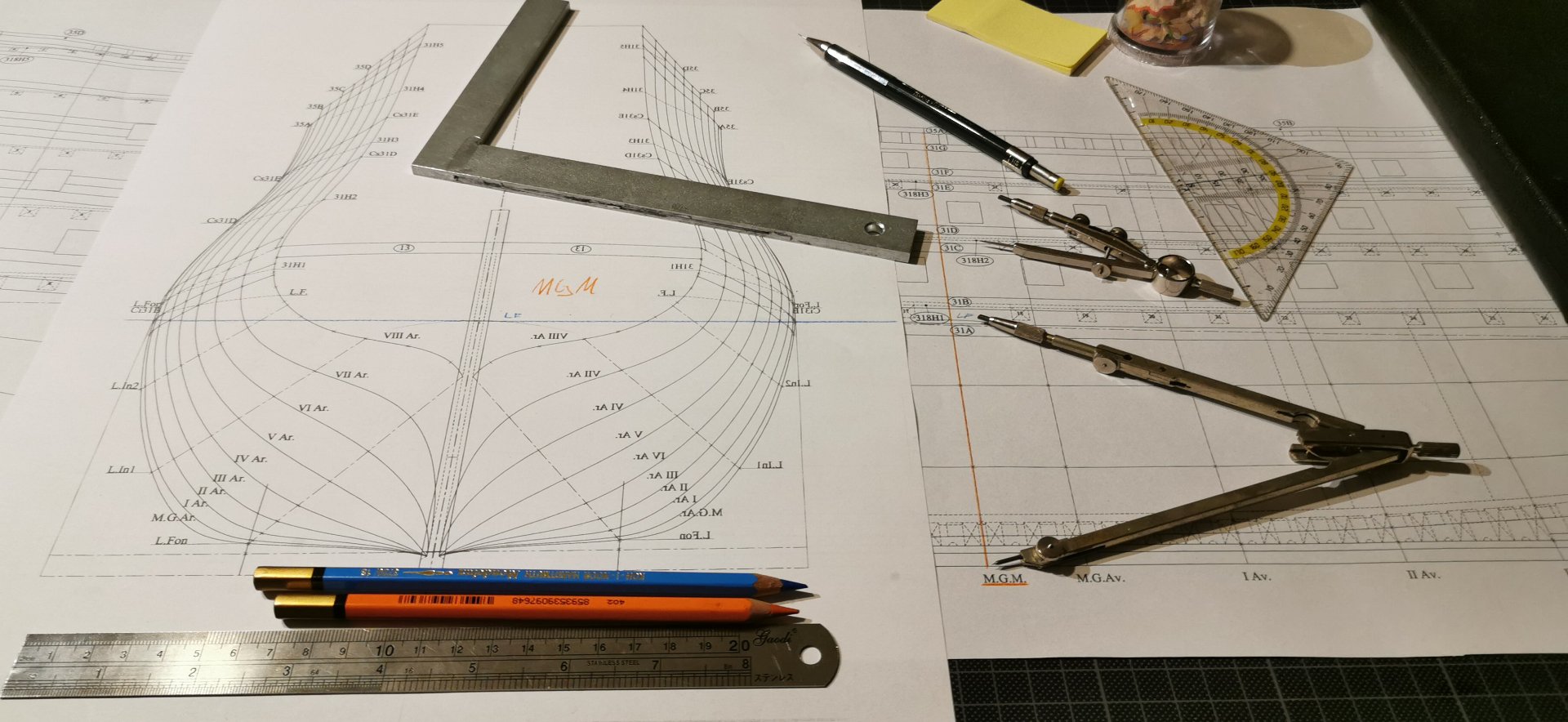
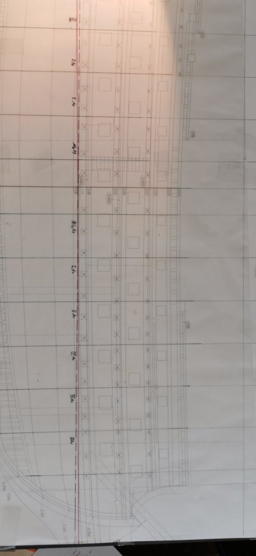
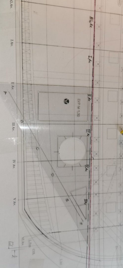
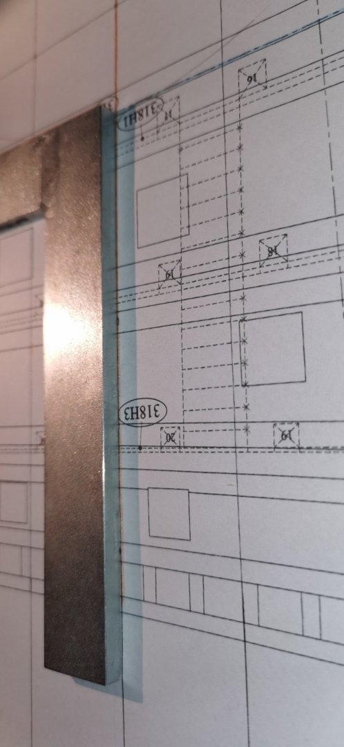
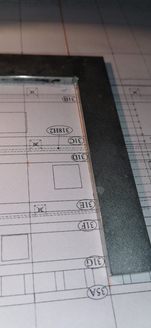
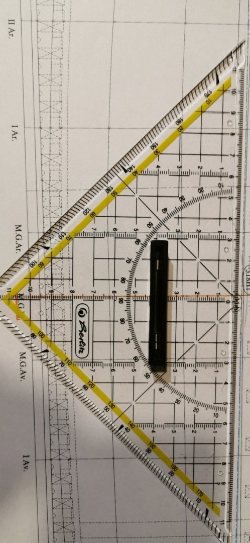
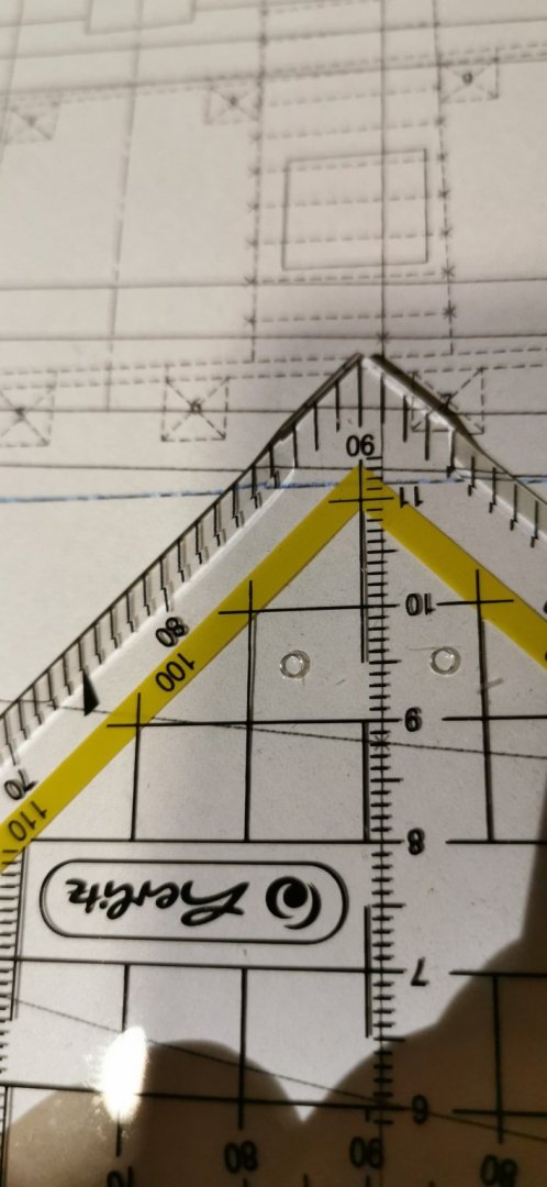
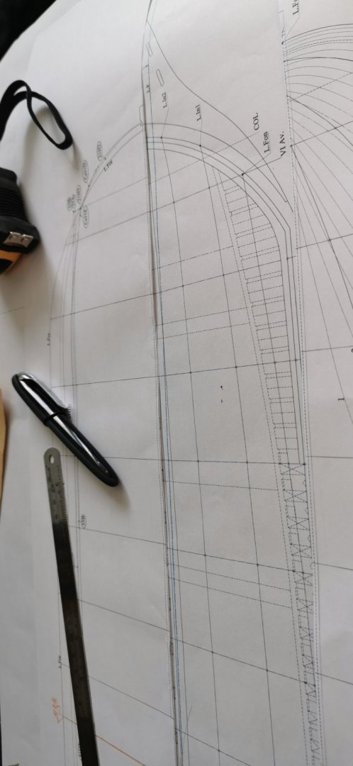
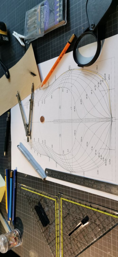
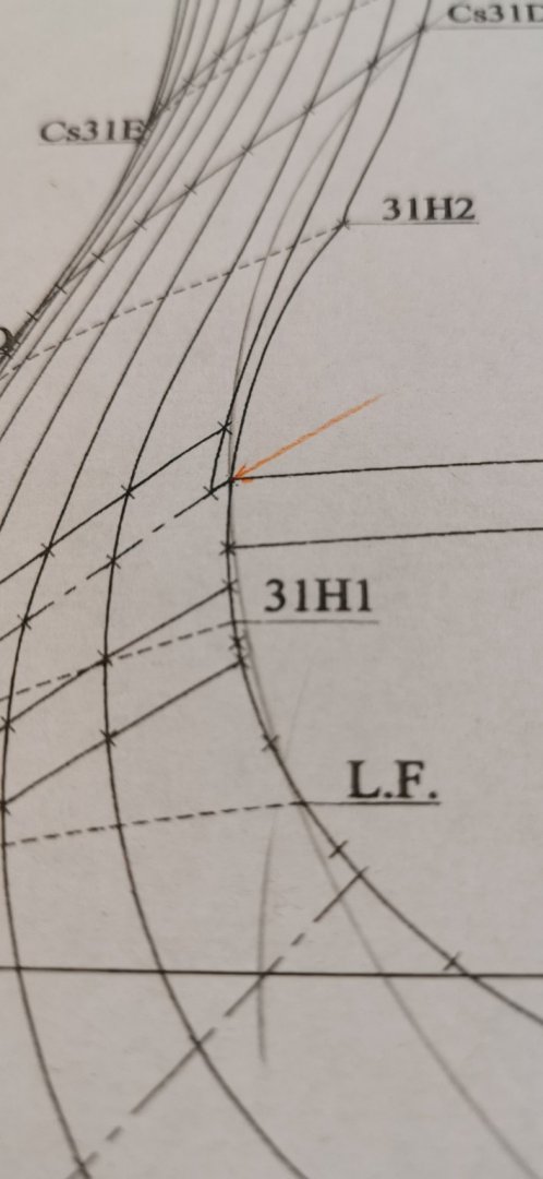
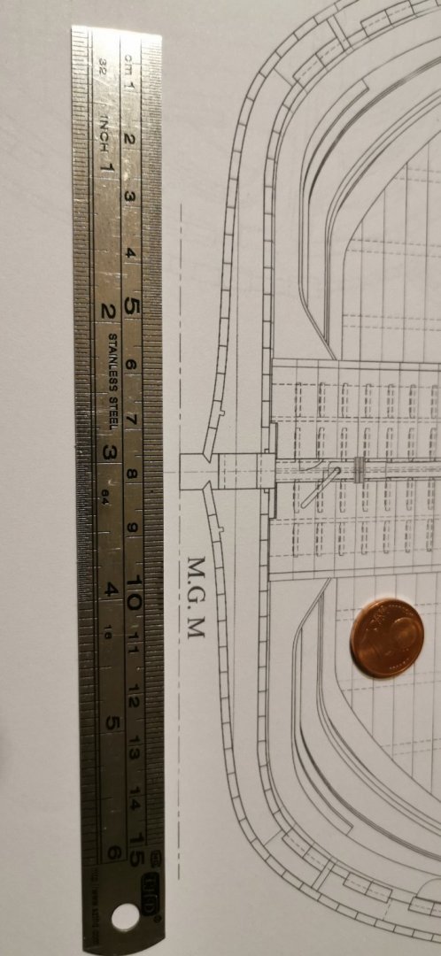
Short view through the periscope down in the boat for those who are interested: A.) CHECHING SYMMETRY B.) LAYING THE CWLs I have seen the Russian videos about hull constrution and symety tests and are following this path through out the next days. A.) Here my first pair of compasses test to symmetry for the Ar-bulkheads: If the line meets the crossing twice exactly on starboard AND portside than my copy is exactly right done... "Constructing is always and in anyway much more exactly than measuring." B.) And by this I pointed out the line of I Ar. by a yellow aquarell pencil and was able to lay the L.F. (French = CWL) Let's proof the concept: Starboard hits the LF-line at portside, too - so the big question is if it is rectangular to the CL? 😁 YES! 😁 Now the same for all the eight other AR-bulkheads. After this turning in the Av.-segment towards the stem.


-
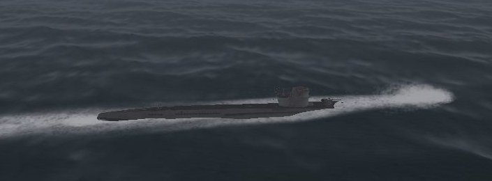
Hello colleagues, as I got this Russian video I got some idea how to inspect the plans accuracy very easy. So I will follow this double check method and dive away fore some days... ...and yes I do play Silent Hinter III 😁😁😁
-
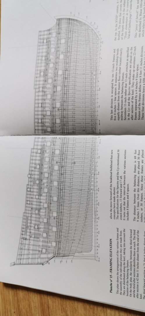
Dear Jaager, the hull's shape (as with RENOMMEÉ one more wonderful example by Ancre) are perfectly for being displayed upside down to show that wonderful full lining of the formers*. Nothing is as elegant as a baroque former model! But I think I wouldn't face towards the saving of wood - I would face the run of the bottom flat surface line ("level" is right word?) this is "bestly"*** done by following the one of the few plans I did not copy&resize: The Framing Elevation Plan - we certainly do safe wood and money but by sacrifying the enormous effect of the original appearance due to penny picking - (in my point of view a fully planked PoF model is a sin to all those that want to learn something as all the detailing done in the inner parts of the ships stays hidden to the viewers if not one side stands unplanked to give us these pedagogical view into the minimized original thing - but on the other hand nothing can be more prototypical that's the receiving of absolution {to stay in a religious wording}.) ^Picture***** I am on the other side of the front line and do say: "What you will never see is to be done to be useful to it's reason of construction - but nothing more. But to get the wonderful elegant effect I would sacrifice a bit of my dogma... 😉 _____________ *I do think about a very small NPoPF** (in 1/144 or 1/192?) to show the beauty of the skeleton hull****. And being build from the plan without cutting in the gunports. **N_o P_lanks o_n P_lastic F_ormers painted as wood ***as I learned in a Dublin pub... 😉 **** The temptation is not to try to imitate ivoree 😁😁😁 *****...and if you look on the palisade of wood in front of you it was safer to do your duty with the 36pfds 😏
-
Hello Jaager, thanks for the helpful advice. I plan to build in a 1st step an easy mock-up PoB unarmed hullmodel from cardboard or MDF to catch such troublemakers before investing money in the real model! I think I will follow the usual way of PoB-building by a full pice of plywood under the 36pounder deck with a groove for the midlel board. The spaces between the bulkheads will be filled with softwood. So I can take the water lines at additive points of fastening the planking. So every bulkhead has the deckbeams under the decks from the cuts. By this I will also know the thickness of the panks and wales. Here the MGM: And the bulkhead and the cut side by side: I think of planking the hull in plastic to be able to imitate the grain in sanding the plastik stripe. But I am not rally shure, as I may use wood due to the easier handling (on the mockup I will have to look for the right thickness of the cardboard layers on the bulkheads. My idea is to plank this model in a way I get a planking plan for the real shipmodels. Under water there is a thick paste over the wood idealistally in light white - realistically there was sulfur in it so it will have looked yellow -grey-dirty. 🤔😩 But as we all do play in a nice modeling world I will paint SP white as snow due to this here is no need for finescaling the planks under the anti-fouling layers of plumbum, sulfur, &ct. As far as I know is this technic due to the fixing of the formers by nailing them on the wales - so the planking could only take place between the Wales and running parallel to them. What is going to give to us a very harmonic appearance. Here it is clear to see that the Wales arend pinned onto the planking they are the start of it! But PoF is far out of my thoughts, abilitys and budget! And I am not a man that would build a French ship in a typical British manner like an Admiralty Model. I am much too conservative for thinks like this. Sorry I am and old and old fashioned man. Showing the real wood construction is a great act of modellism. But using an idealistic or symbolic pattern (as in a typical navy board) of formers isn't my way to build a model. I do like Navy Board models very much but only if the name's prefix is an H.M.S. - sorry for this diminished point of view. But back to what is to be done - the French builded ships with a nearly horizontal area admidships giving an elliptical area - what contrasted the thumblehome of the hull above and makes this ships so very interesting to me: This makes the ugly Heller SR-hull a bit better when you file away the sharp edge towards the planks. Thanks again for your interesting and delighting text! I will draw in the bulkhead plans the CWL /L.F. very precisely to avoid any errors. You are very welcome. This from here now and me... Heinrich
-
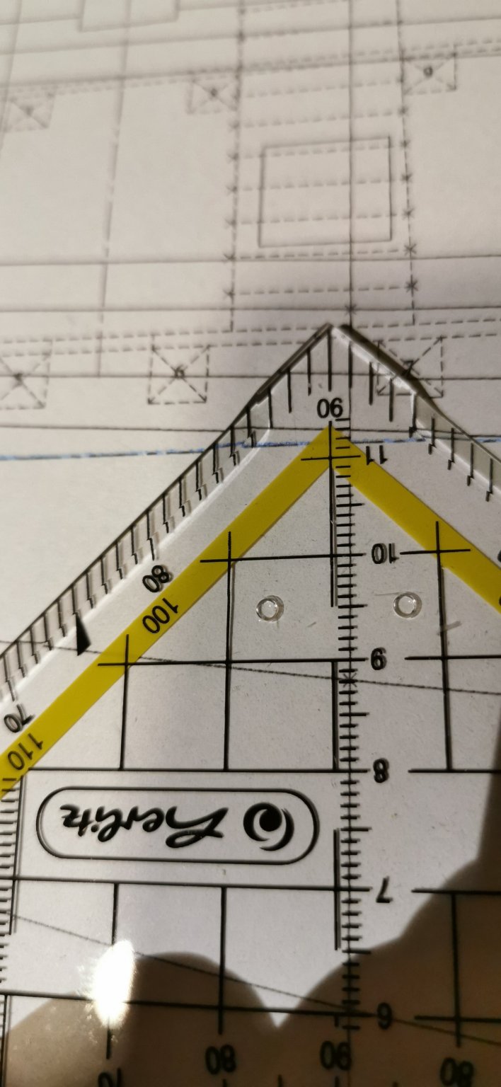
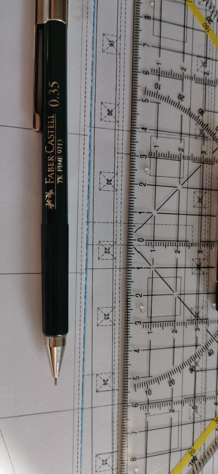
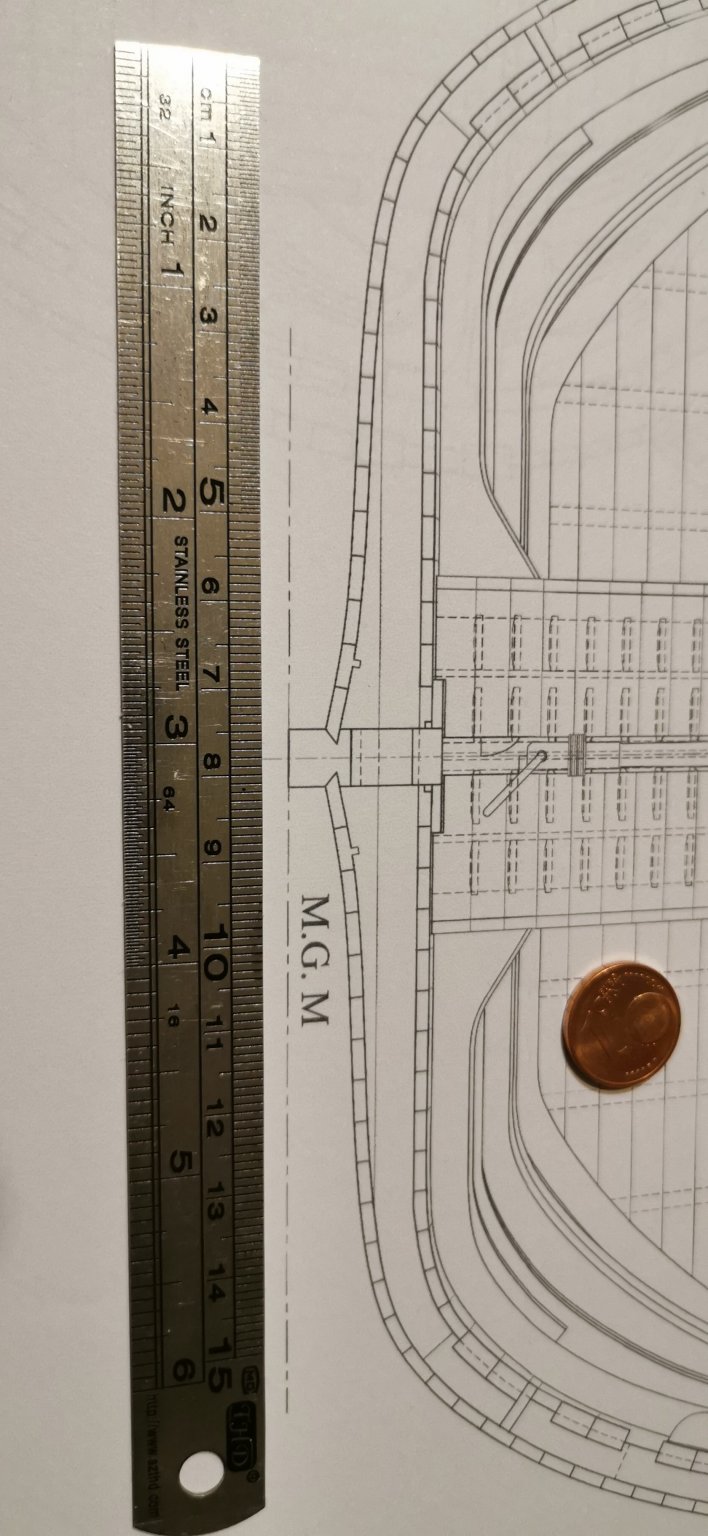
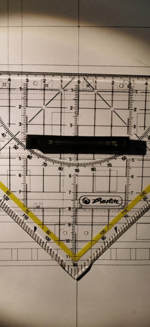
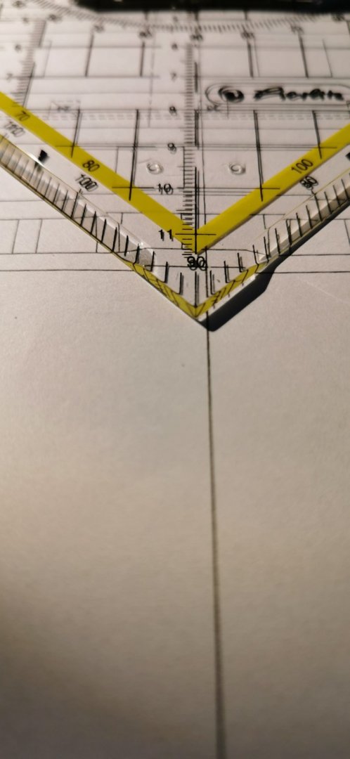
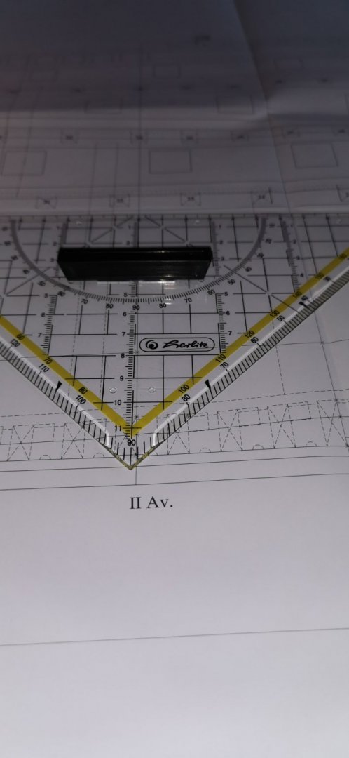
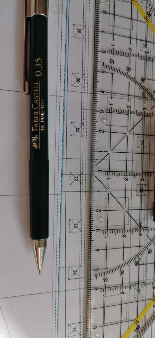
Sorry guys, not too much happened tonight. The big triangle rulers are still missing 😞. So I needed a plenty of time to get the CWL improvised on the main bulkhead/M. G. M. in some acceptable quality... 🙄 On the other hand I decorated the 1100mm long ship (l.o.a.) unter my moose's husband to testfit the space needed for the fully rigged ship. So tomorrow more will happen (hopefully) - I do have to join the DIY-shop around the corner and pick up a hand full of heavy cardboard at my girlfriend's company. Thanks for watching! This it was from here now &me Goid night, Heinrich

-
Thanks a lot for your interest, ccoyle, and take a seat! Today I lived in the Copy Shop to get my 1/64 recuced copies in ink. So I managed to copy, mirror and glue together the former plan. So this night I will add the linings on the individual bulkhead plan and than tomorrow start to cut out in card board. But I am afraid I didn't have bought enough cardboard... 😕 So tomorrow I will be able to go to the DIYstore and get (some baseboard for the 1/92 stand and) some thicker cardboard or thin MDF for this project's mock-up model 😁. Thanks for watching in in here.
-
Thanks, Marc, today's day I lived in the Copy Shop and deal with the 1/64 reductions of the plan... So the promised building of the pedestal will start tomorrow... Sorry for this.
- 244 replies
-
- 2
-
-
- heller
- soleil royal
- (and 1 more)
-
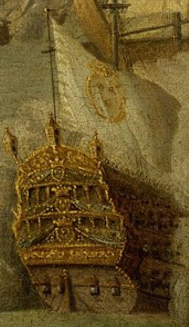
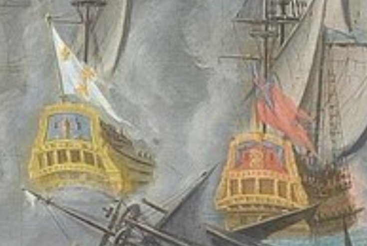
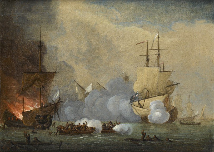
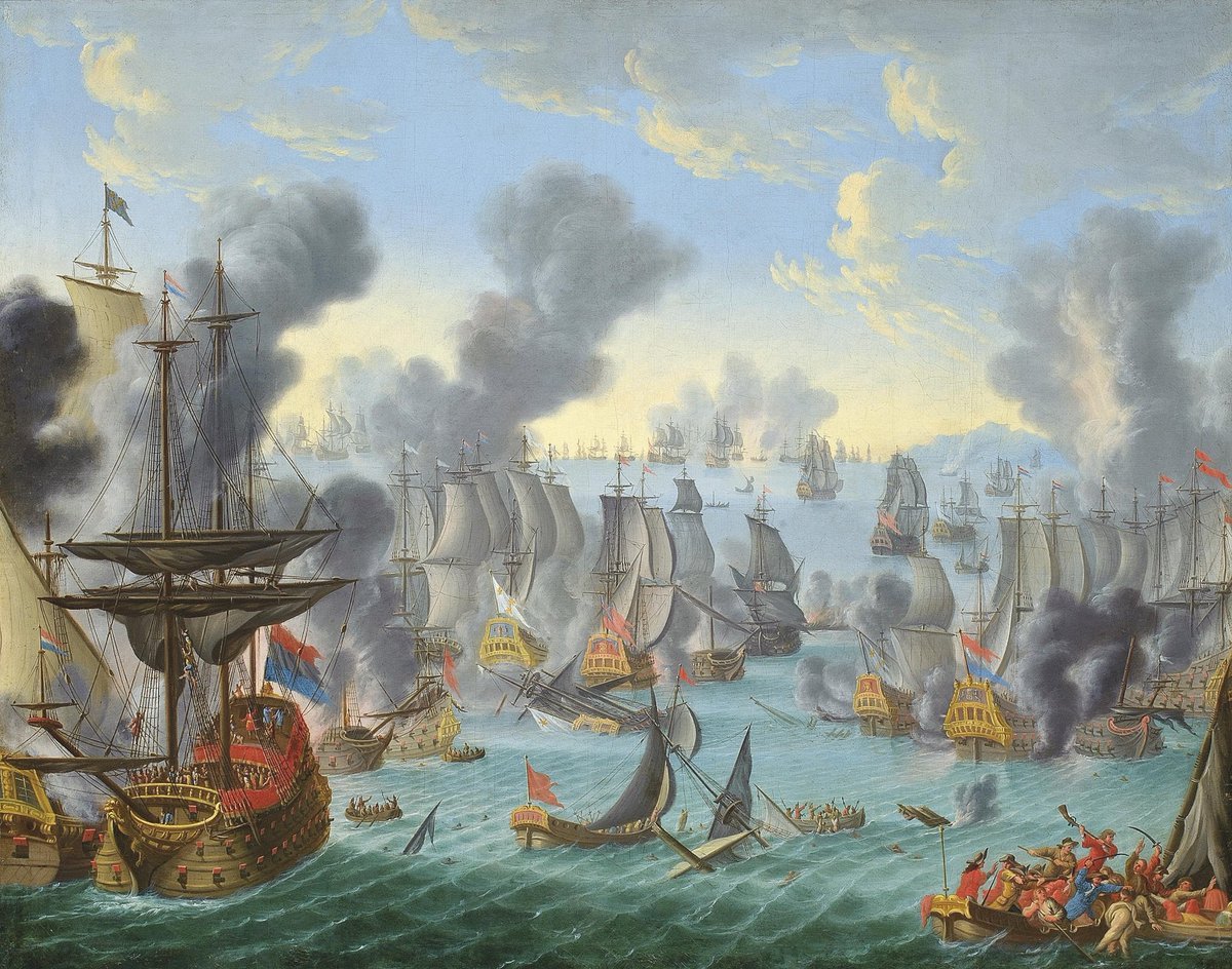
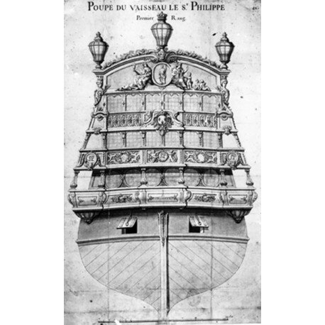
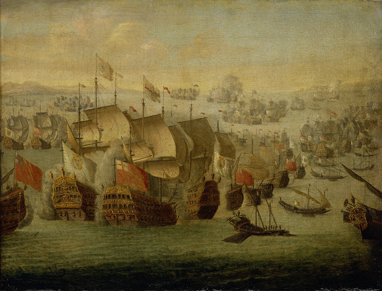
Here the only beliefable picturing of a French Man-o-War in these paintings: But it is an abriviation but it shows four stern gunports to us but the gallerys balconies and an elaborated coronament are missing. (This gives a good prototype for a fine 70th pirates ship from Monogram!) The flag is also wrong because on every ship where the kings was't aboard the insignia in the white flags are missing - "pure blance" was the result (but it is often ignore due to the modern meaning of the flag I think). So we can put away these contempotal paintings as a resilient source. That is a pitty. But one other picture is left that shows a golden transom under a French flag: And this is just a bad joke I think...
-
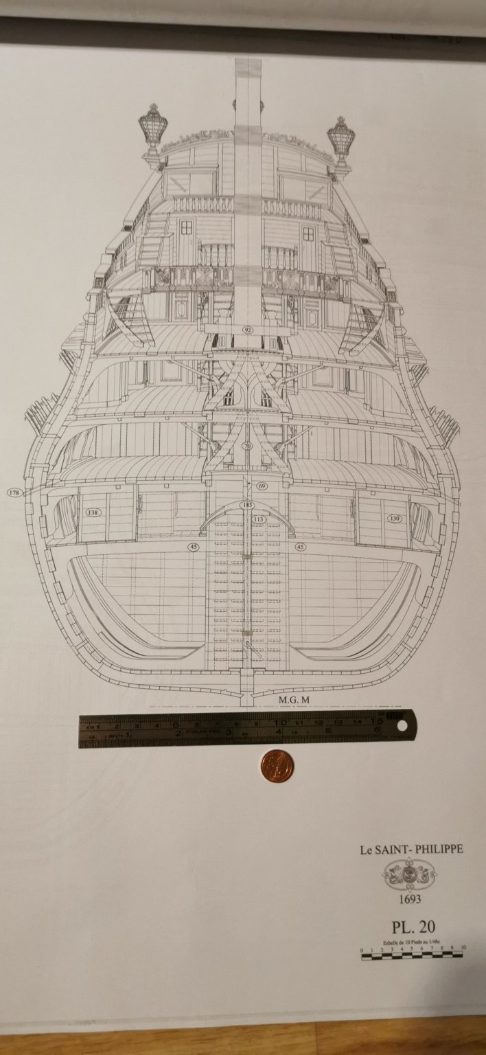
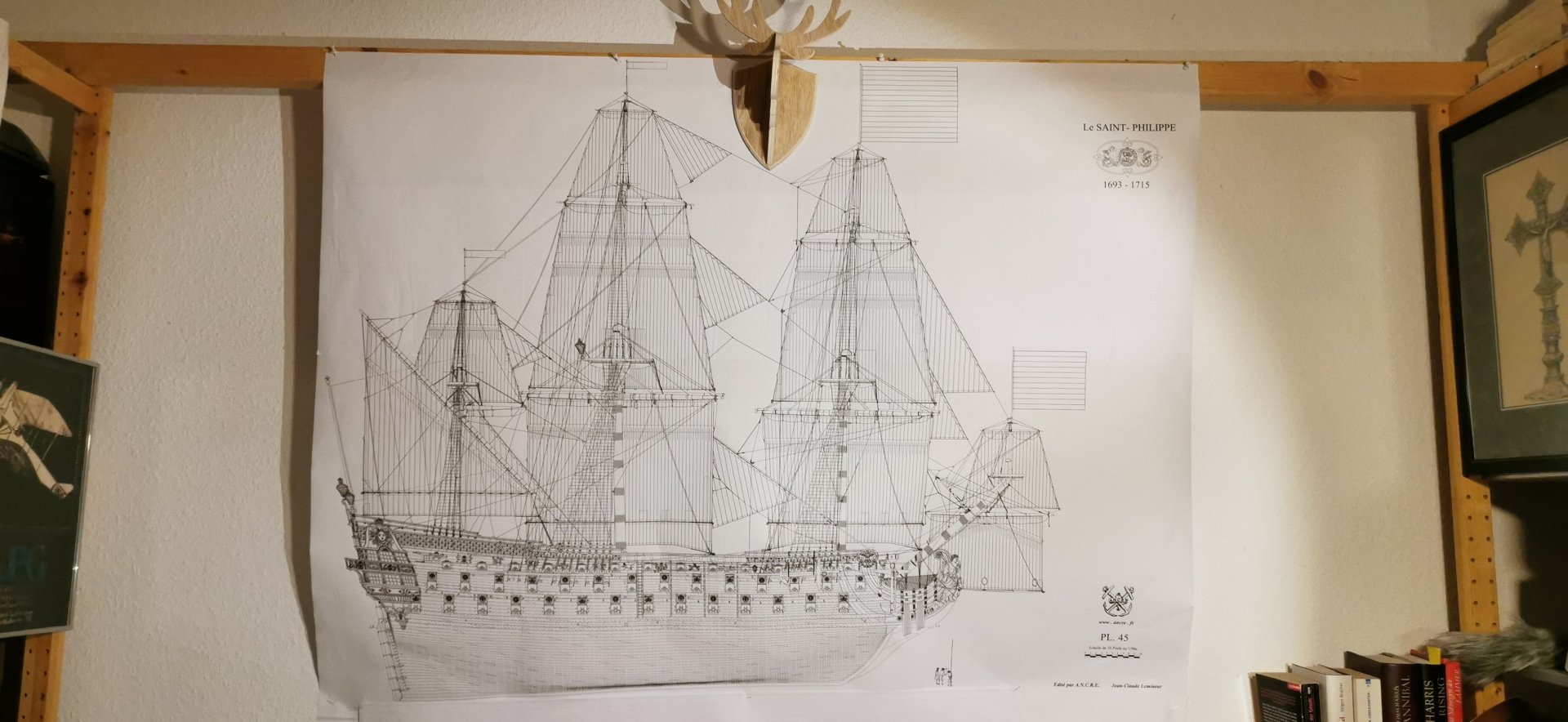
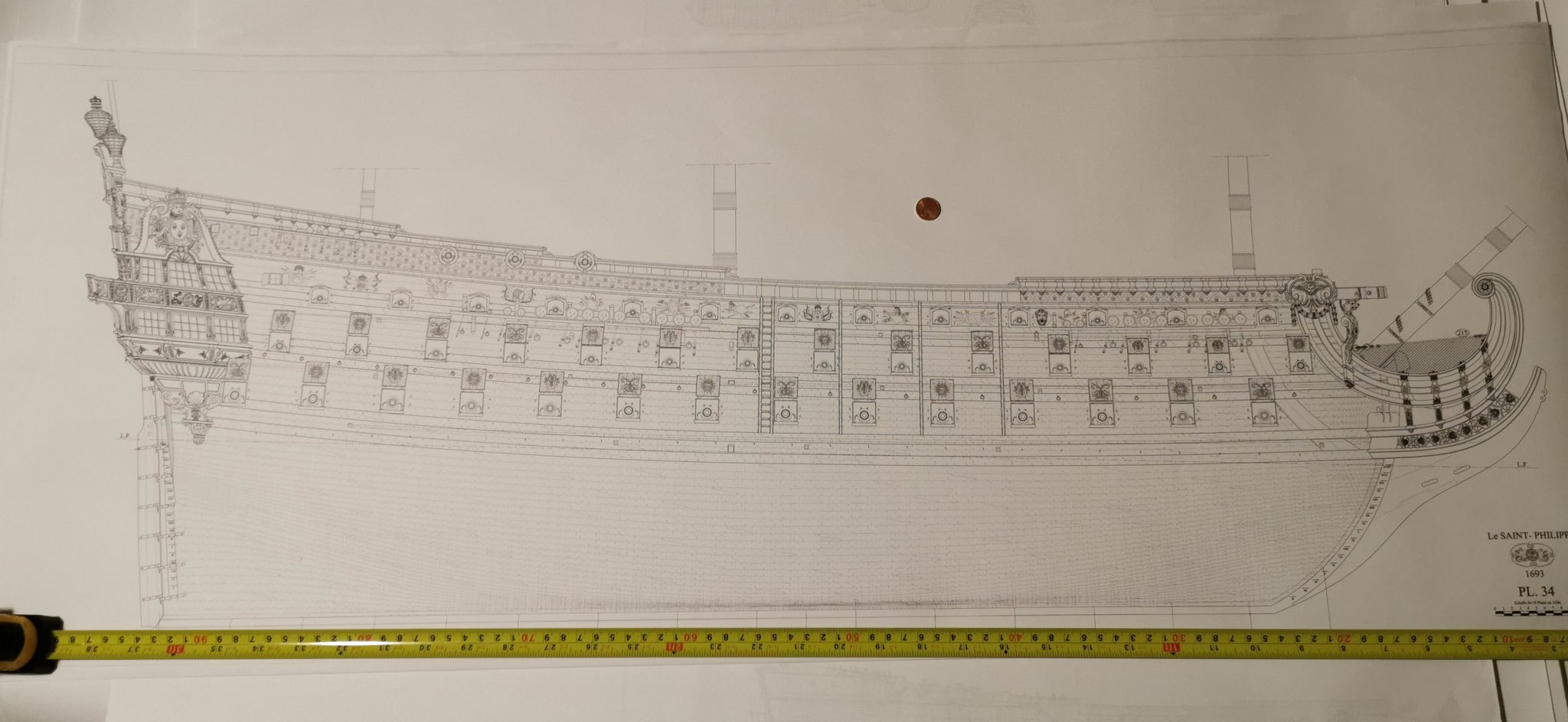
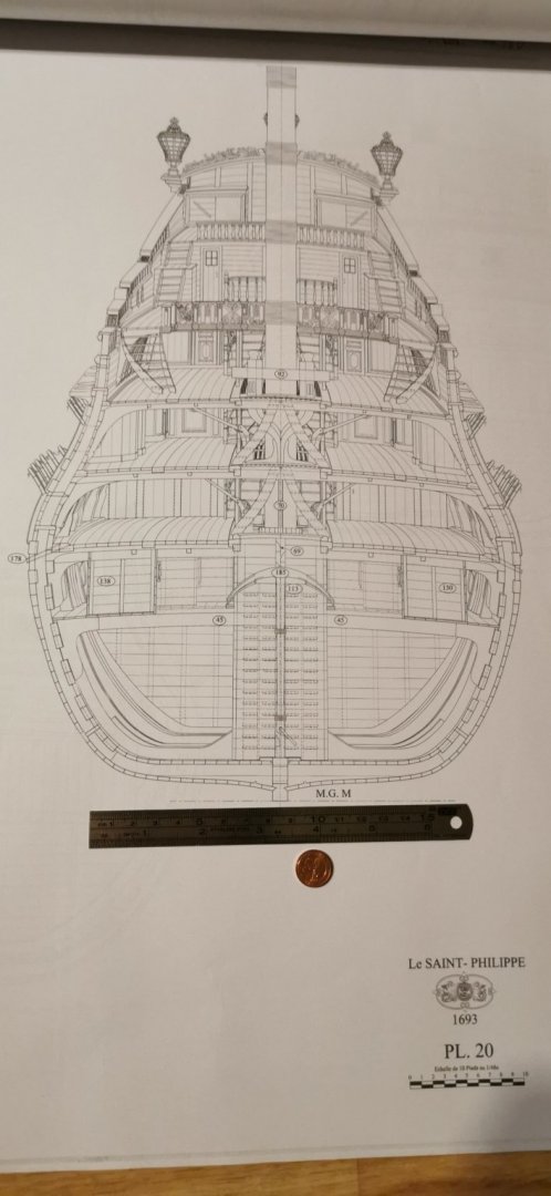
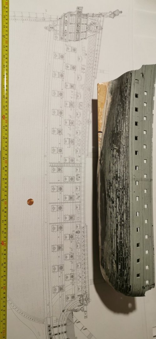
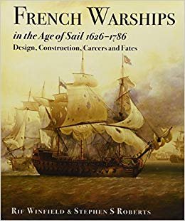
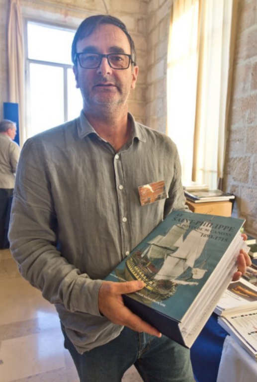
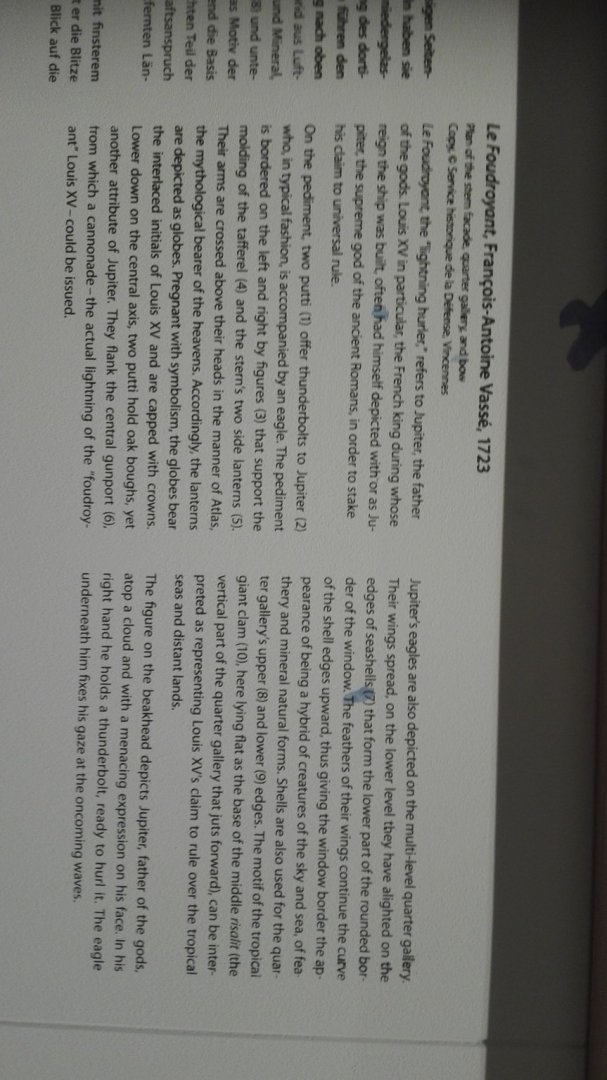
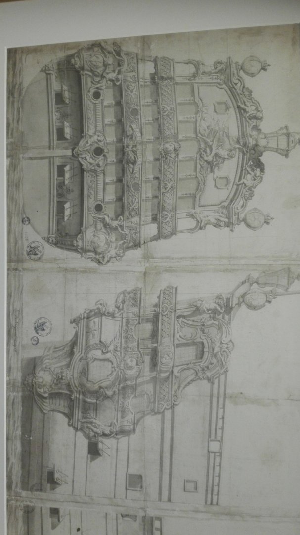
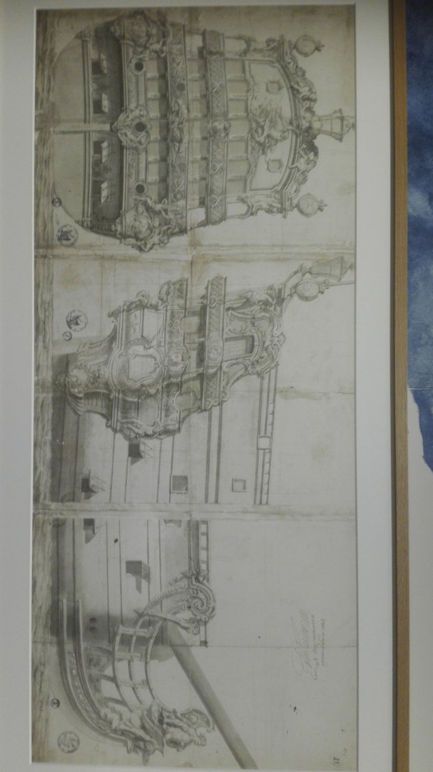
Hello, I do start here my scratch project in SAINT PHILIPPE as a parallel built to benefit from the kit bashing knowledge. The SP was build to replace the lost of the burnt down elder SP-1669 set on beach by her crew and sneaky burnt down by the British. SP-1693 is to be found in some decoration drawing of the Toulon dock yard an in some oil paintings of here only seabattle in 1704 - but like very often we have to keep in mind that the artist was not very often aboard at the battle and preferred to paint in their safe cabinet instead so the results in detailing may leck more than a bit! But in here we will follow all the tracks to the original appearance of SP-1693. The 2nd (our) SP fought in two battles one at sea (Sae Battle of Malaga - pictures above) and her last as a floating battery. Here the well known transom I will show the differences in detail to the Ancre plan (two and four 36pfds gunports for example) show later on. The next source is the book of Winfield & Roberts "FRENCH WARSHIPS IN THE AGR OF SAIL 1626-1786" ...and certainly the beautyful Ancre Monography: But back to the prototype: The SP-1693 was 51ms long in keel and was wearing 90 guns and was reconstructed over 15 years by Mr. Lemineur in an Ancre monograph in 2018 - (sadly there are some Errata in the plans and pictures in there so I will try to give an advice to those I am able to figure out.) this 90 guns will be a problem later on as we will discuss than. Even in 1/64 she is an astonishing beast and I do celebrate her building start in a contemporary manner: The resulting model is of over three royal French feet (324,8mms) length... So I yesterday went into my favorite copyshop and invested the amount of money for a hole Ancre monographie into an ink (not laser) printout in 1/64. Some of the plan's sheets are wrongly named in scal. (So beware to check the scale length bar!!!) Here the Heller hull and the drawing in comparison. And the beautiful side view if the mighty SP. Frist step is to build a dummy hull skeleton from card board to check the needed space in the flat. Hopefully you like this project limping behind the Heller bashing: Sorry for my bad English in before.

-
Hello, blowing the dust from the hull I am in reorganisation the yard and give some furth r progress to this rebuild in the next days - the pseudo-wooden pedestal will be ready end of this week (hopefully).
- 244 replies
-
- 3
-
-
- heller
- soleil royal
- (and 1 more)
-
That looks great, hyw! You do build her in 1/36? Could you tell us a bit about these "inaccuruties" in the plans please?
-
At the moment I am awayting my barrel set.
-
Hello Javier, is this again scaled down 1/210 as with the Ancre plan build Tartane of 1863?
-
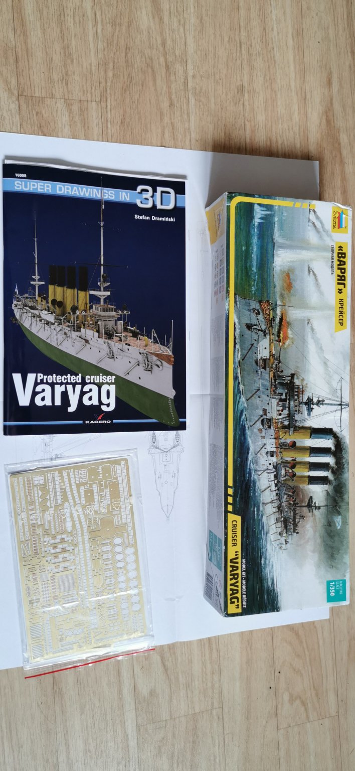
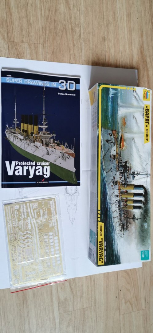
Here the drawings Literature and the photo etched parts.
-
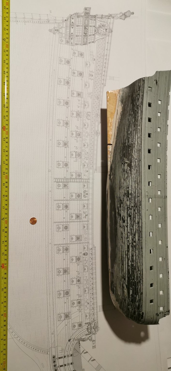
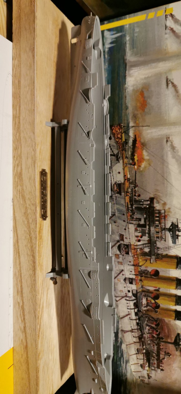
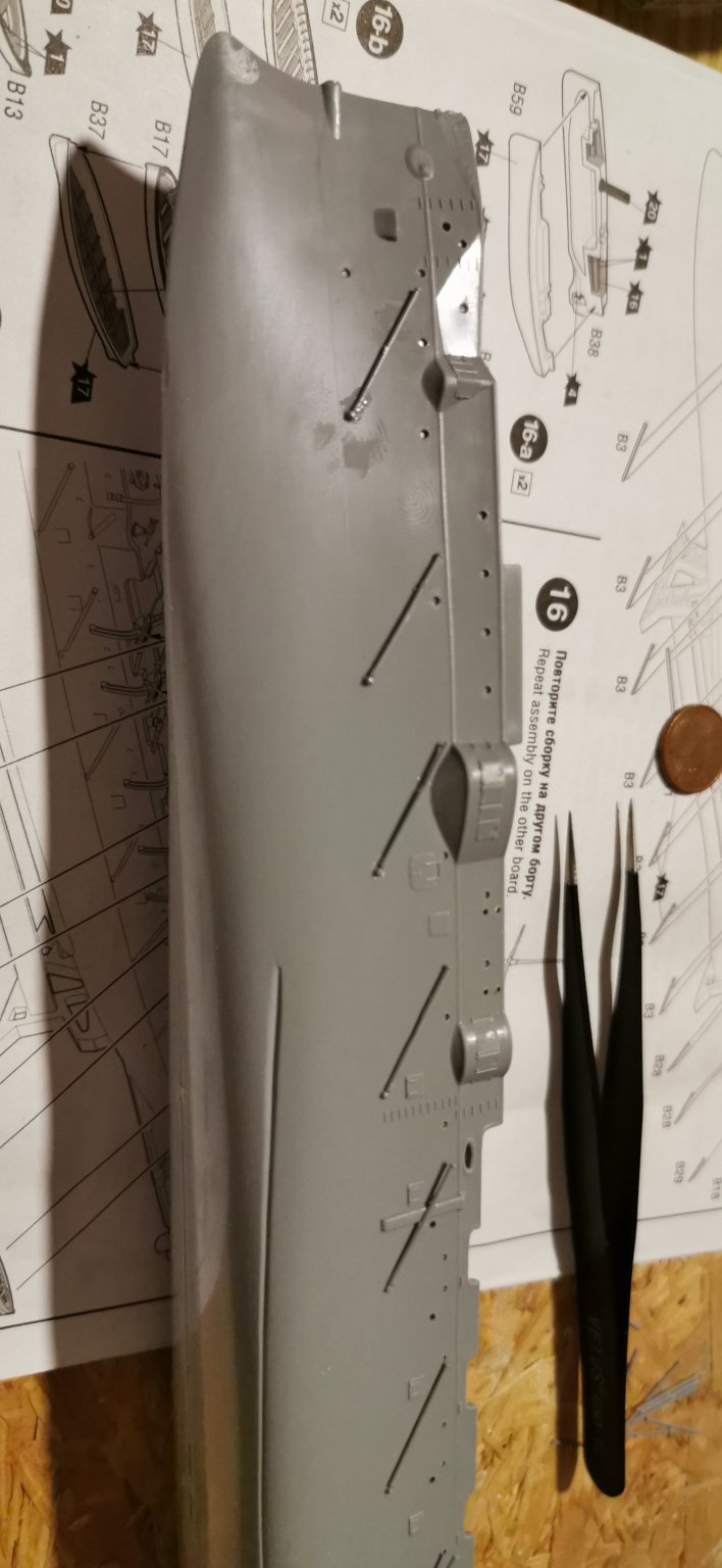
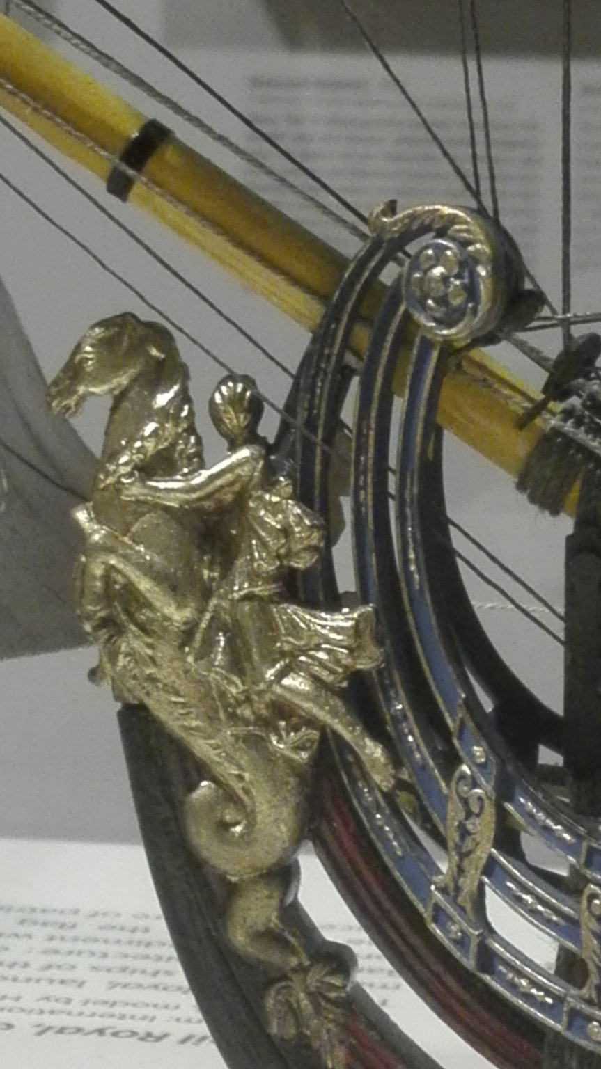
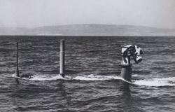
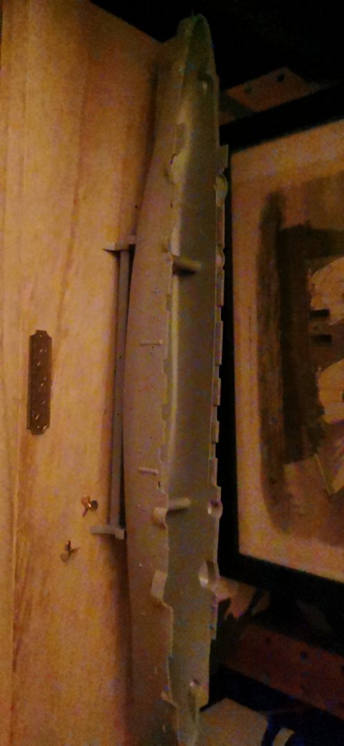
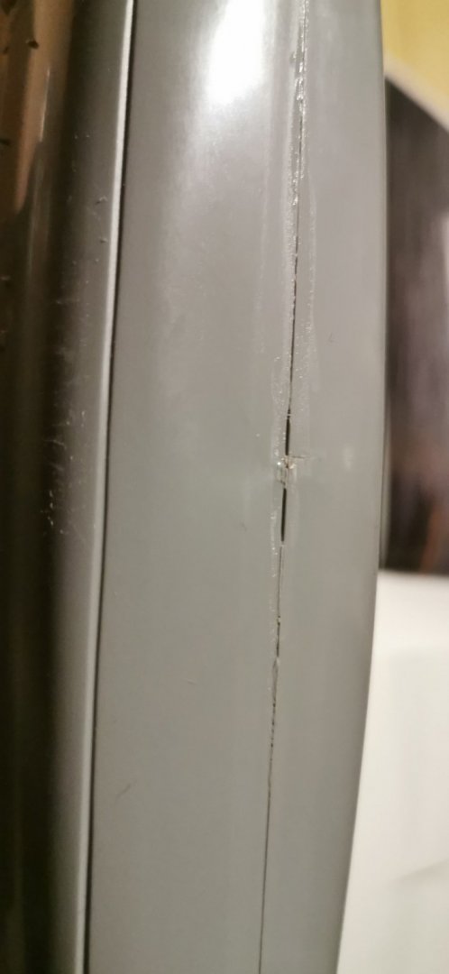
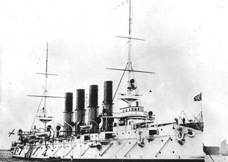
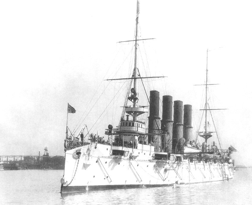
Hello modelers, after an absence from here I went boring in my life; sad is a life without ships. So I got a magnifying lamp to support my left eye and I hope I could build some model until the very end. I love this ship due to its nice design and the light white colored hull (I am still looking fot the right yellow for the funnels). The Russian protected cruiser VARYAG was an astonishing example of heroism in the naval history. Facing an overwhelming enemy the captain didn't give up and surrendered. VARYAG is one of the ships being lost in full fight under its free flying flag. The Japanese raised the wreck and added her into their fleet as I.J.N. SOYA. (Look on these bars added onto the deck!) and this wonderful figurehead*. But I am starting with the end - the Zvezda kit shall be shown as she was on the visit of Czar Nicolaus II. on the 28.IV.1898 in her pride white coloring with green underwater part and the yellow funnels. So the emporers standart will fly over the kit - {but does it has had the white colouring of its Port Arthur time or was it delivered in the black hull painting scheme for the Baltic fleet?} She was built at Philadelphia at Will. Cramps shipyard due to the Russian shipyards were all working on battleships. The construction was altered to PALLADA, AURORA, DIANA giving her more speed, protection and heavier armaments. A good like for the model in the St. Petersburg collection is this: http://special.navalmuseum.ru/collection/ship/modeli?id=1365 The kit is very well known and I do not repeat the reboxing made better by others. I added the Eduard PE parts and a gun barrel set to it and looked very intensive the the funny video series of Harry Houndini about her build: Who gave me some interesting advise to add the torpedo net booms first, as they are quite fiddly parts. Torpedo net booms do bear the wigth of an iron net hanging in a distance infornt of the hull in the water. These 750 tons nets do catching the incoming torpedos and stop their speed so the do sink to the ground. (At Port Arthur one net kept of 113 Japanese Torpedos.) But they are important as the structure the hull's side into diagonal stripes. And the are not too easy to be glued on. I did need 3hs to adjust them. (I am still looking for pictures of the torpedoboot rigging - but this seems to be under deck to be attached in case of adding the nets, too.) I get rid of painting the bronze parts right (names plate and propellers) by a spray can of bronze colour. (I learned not to overestimate my skills!) What did I told my colleagues every time "Keep is short and simple" ? The hull's halfs are good and easy to connect by Tamiya cement and putty. As I am still waiting for a pair of bronze pedastals I cannot enclose the hull by the decks at the moment but the hull itself will need some further detailing putty filling, inner strengthening for the pedastals and some sanding. So that's from me and here and now, Heinrich ______________ *Inner voice:"Oh no Henry - don't overdo it!!!"


_svg.png.c61d20d739f82b2c2ebdf914136f2b79.png)
.jpg.f8f6d3031148129c467076a11e0e964e.jpg)
-
Hello Marc after my short speach on the exhibitions conference about "Pomp to Senslessness" on wendsday I will try to make some further photos of the SR-model for you. Great work you have done!!! In a hurry, HdS
- 2,699 replies
-
- 4
-
-
- heller
- soleil royal
- (and 9 more)
-
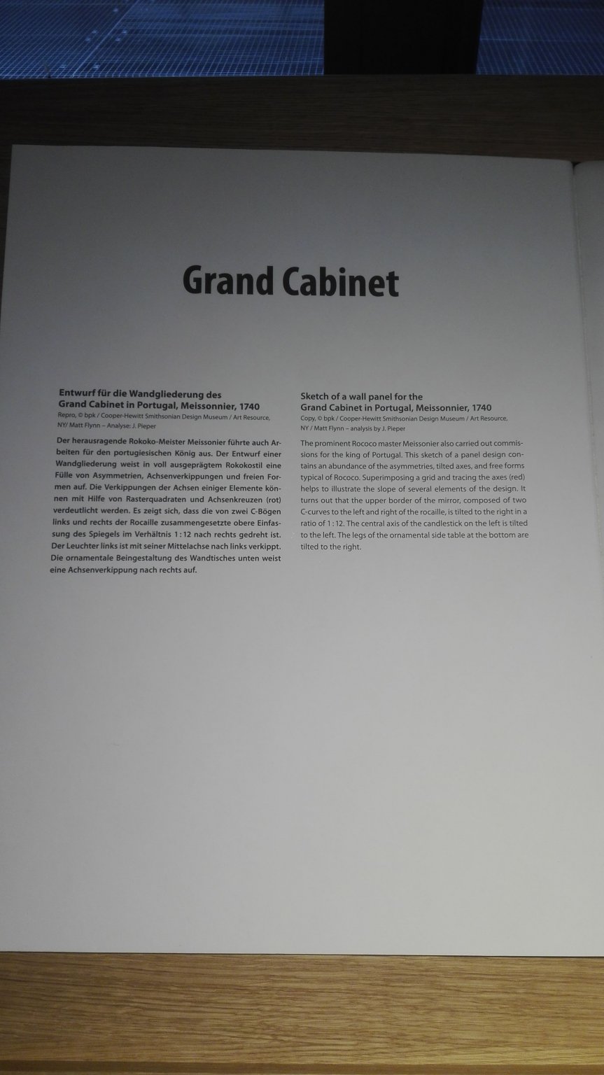
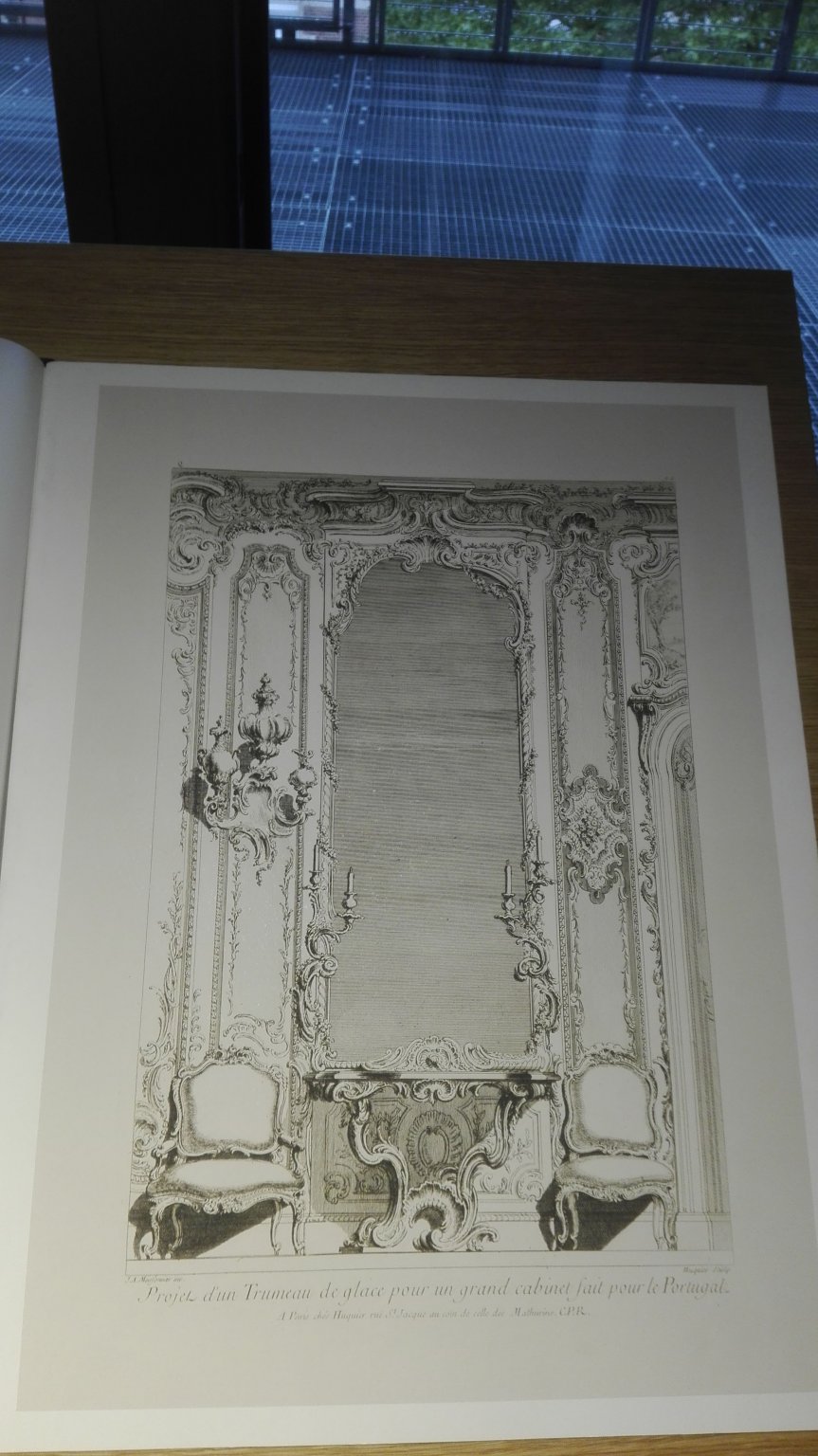
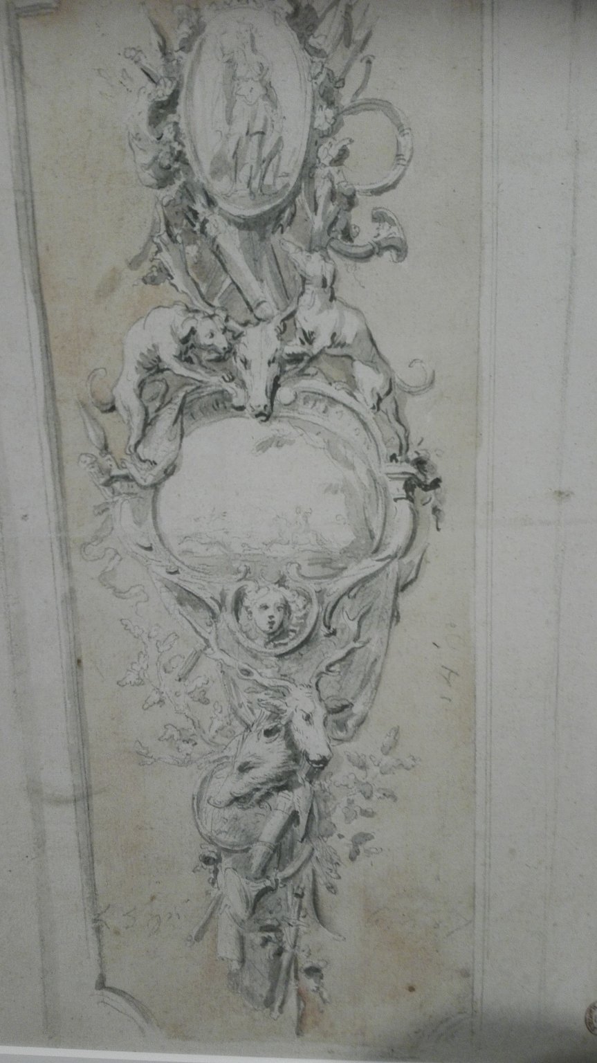
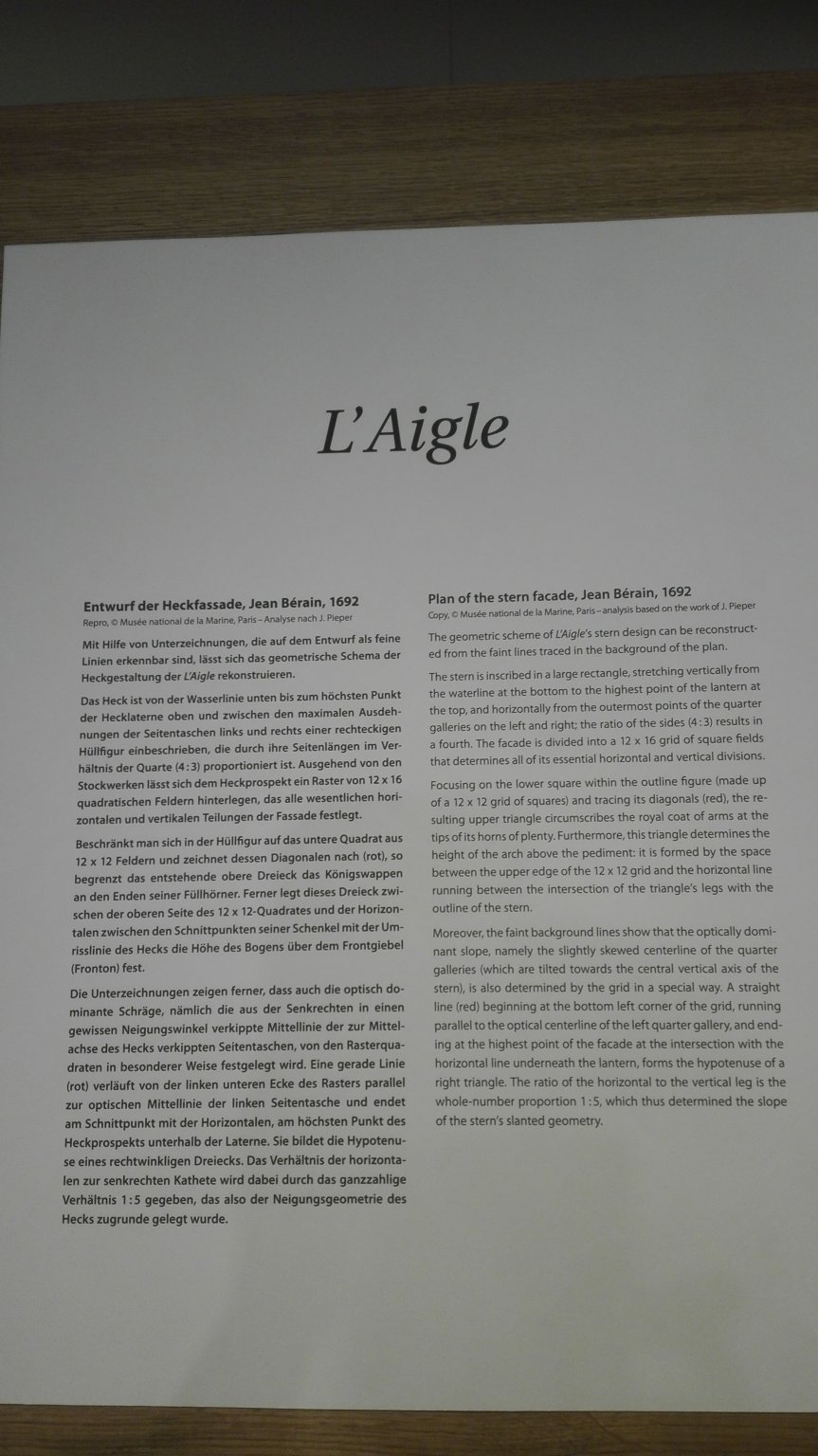
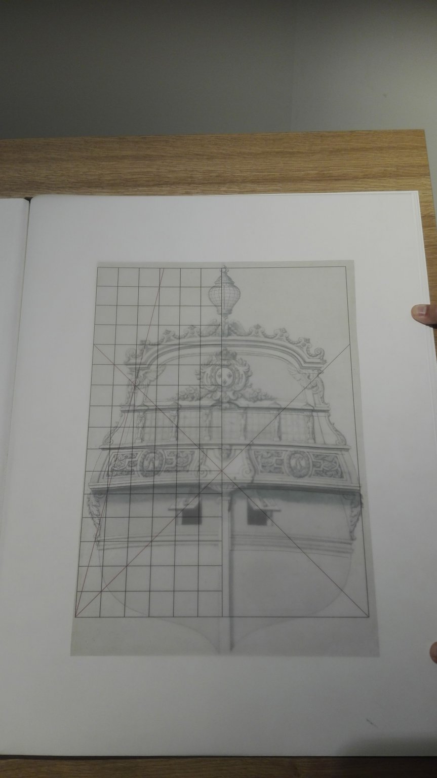
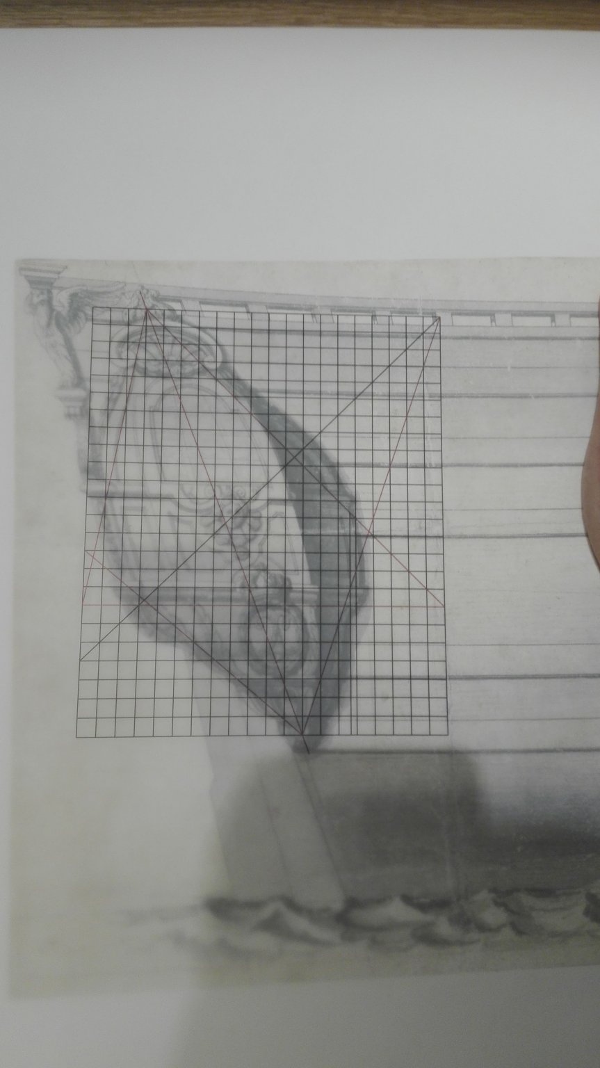
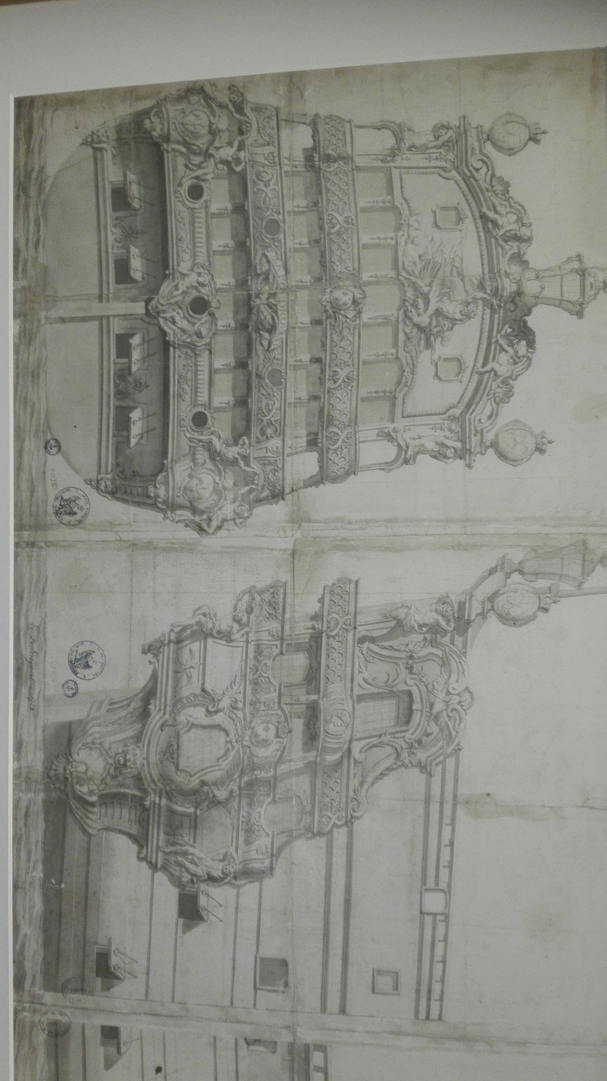
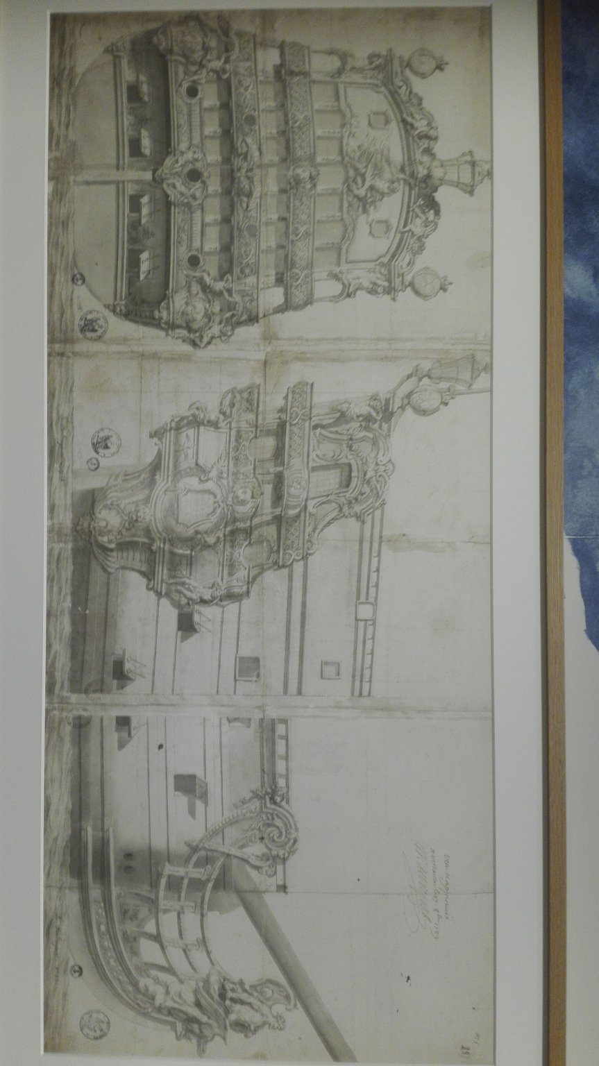
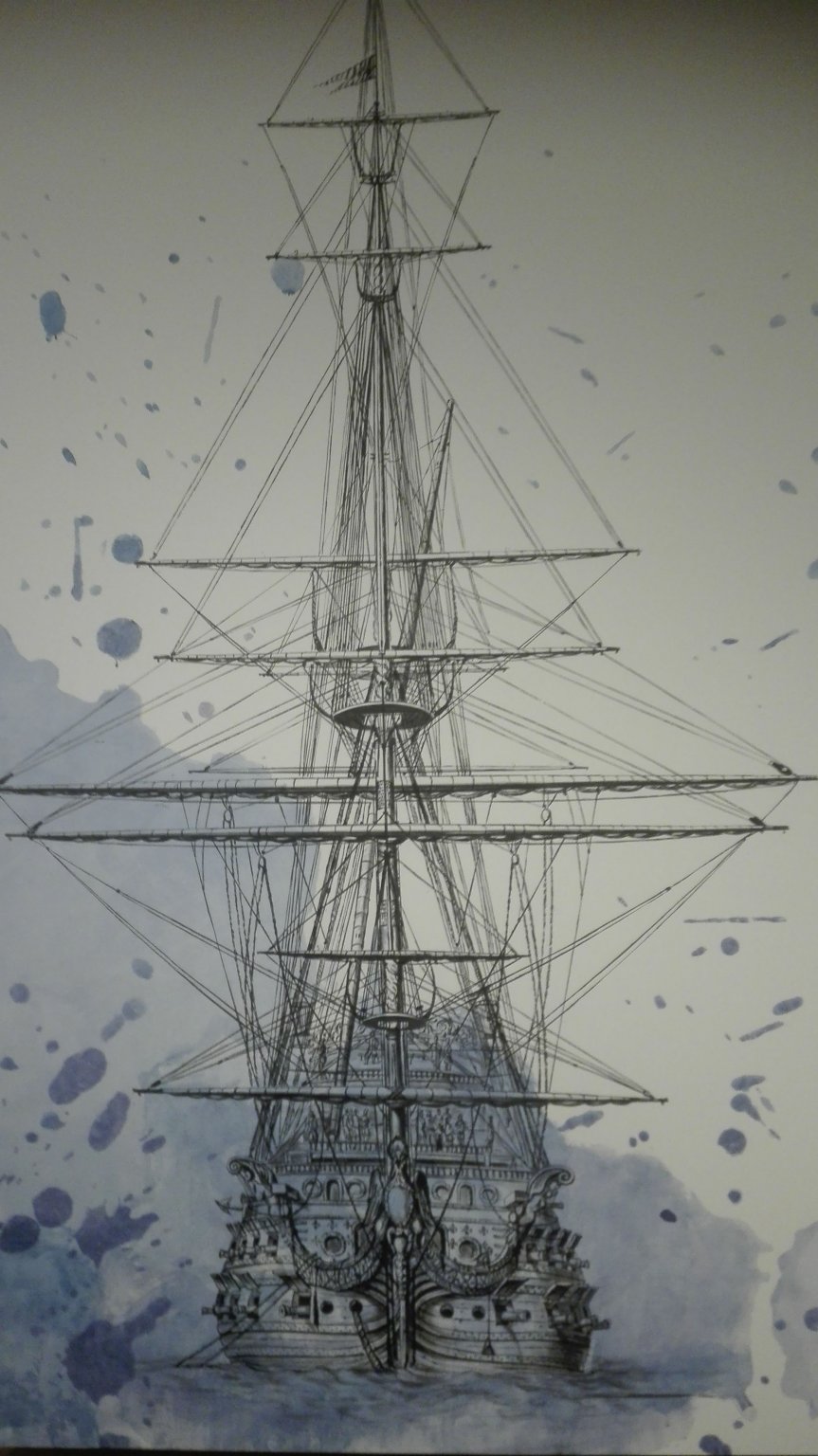
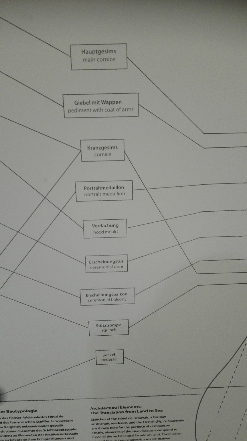
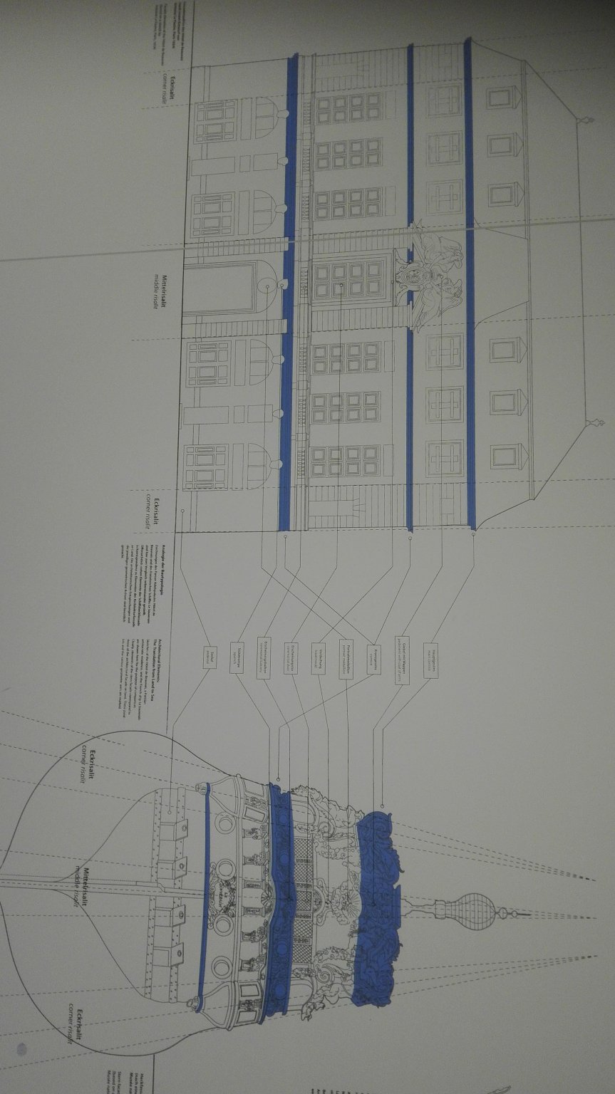
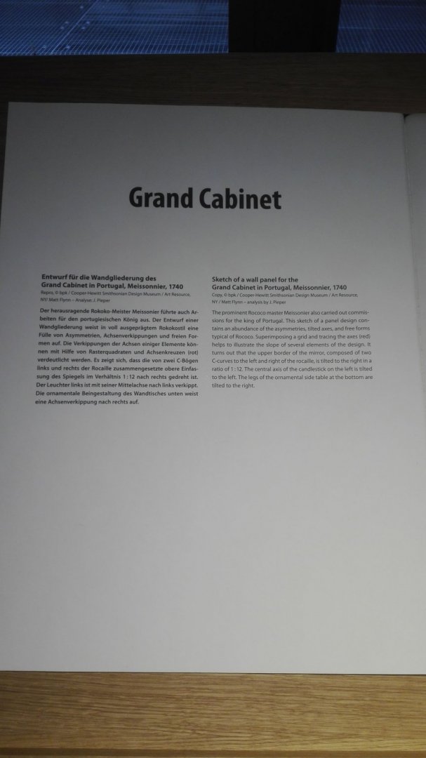
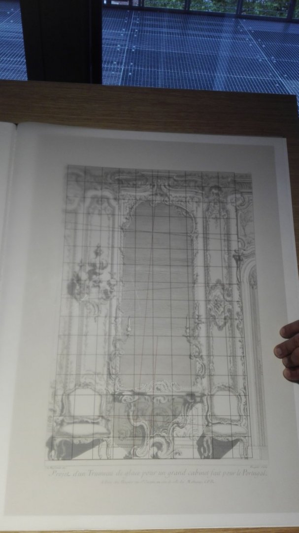
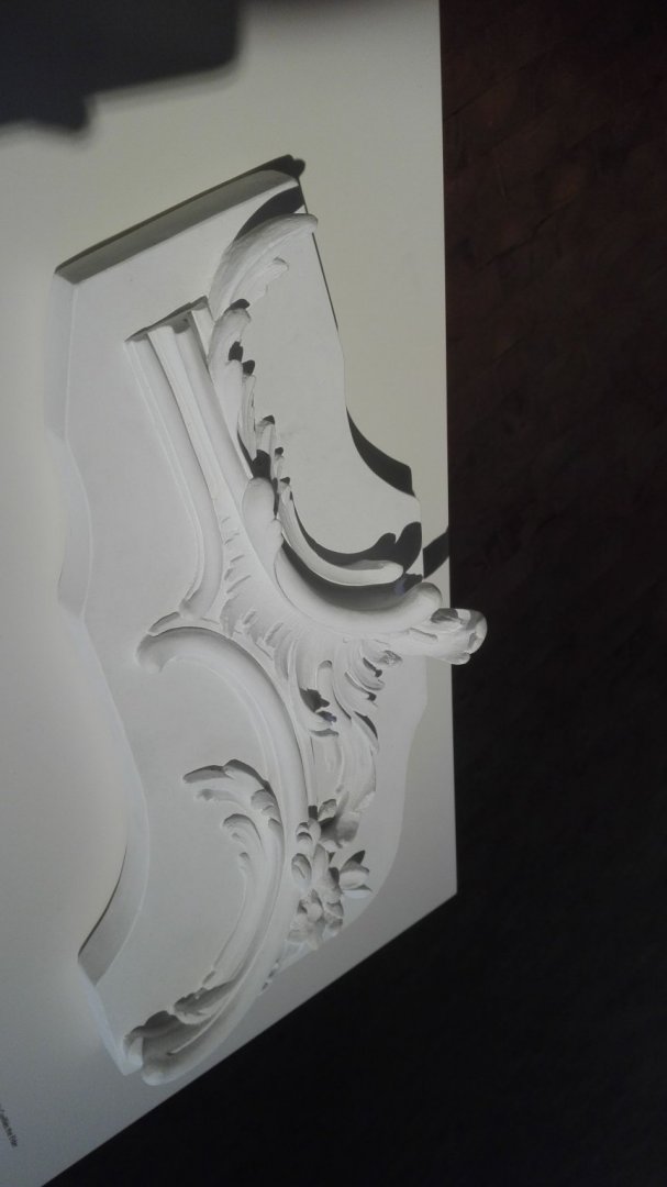
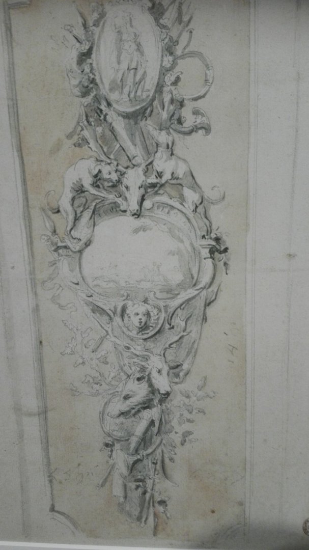
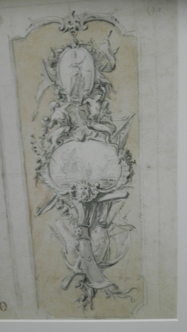
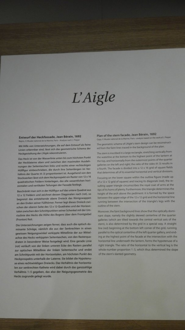
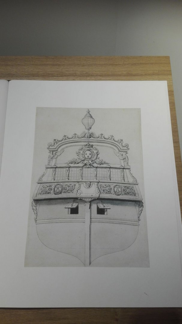
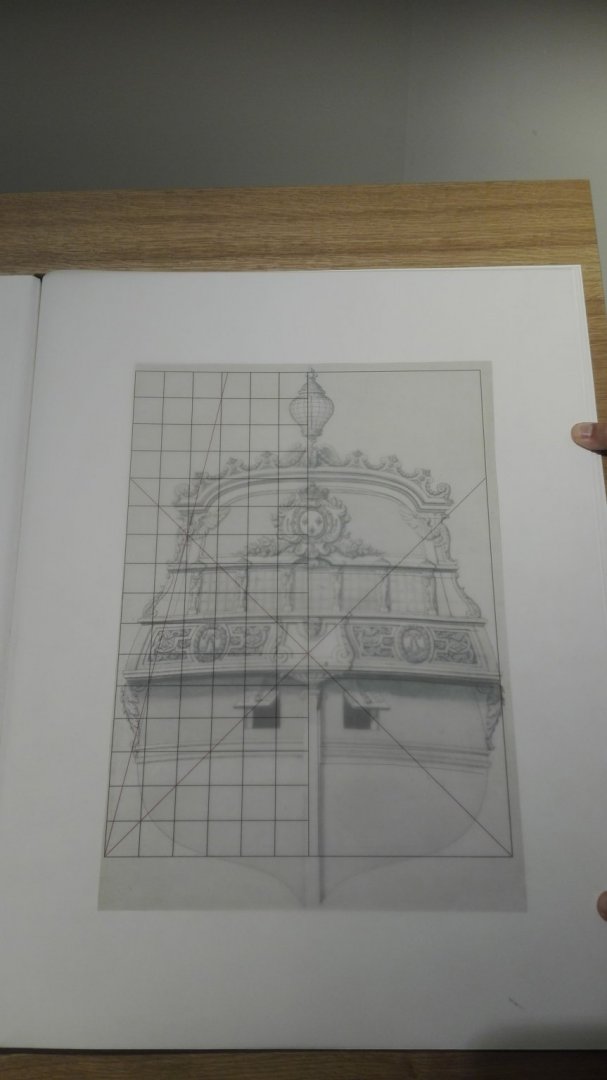
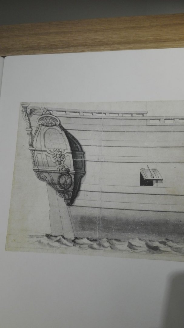
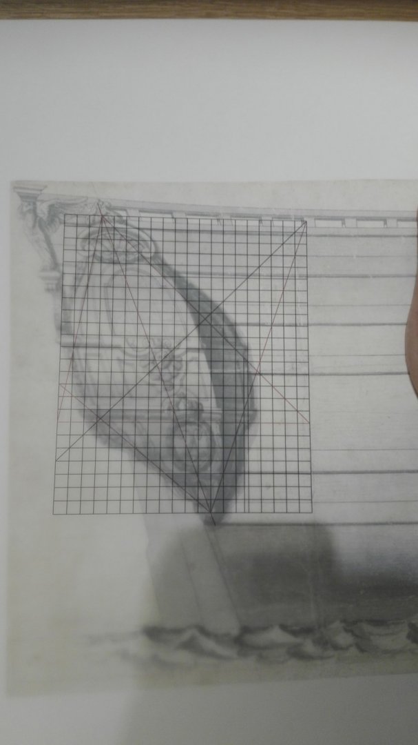
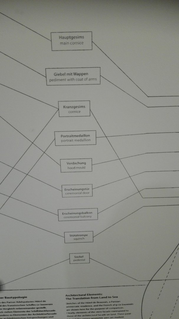
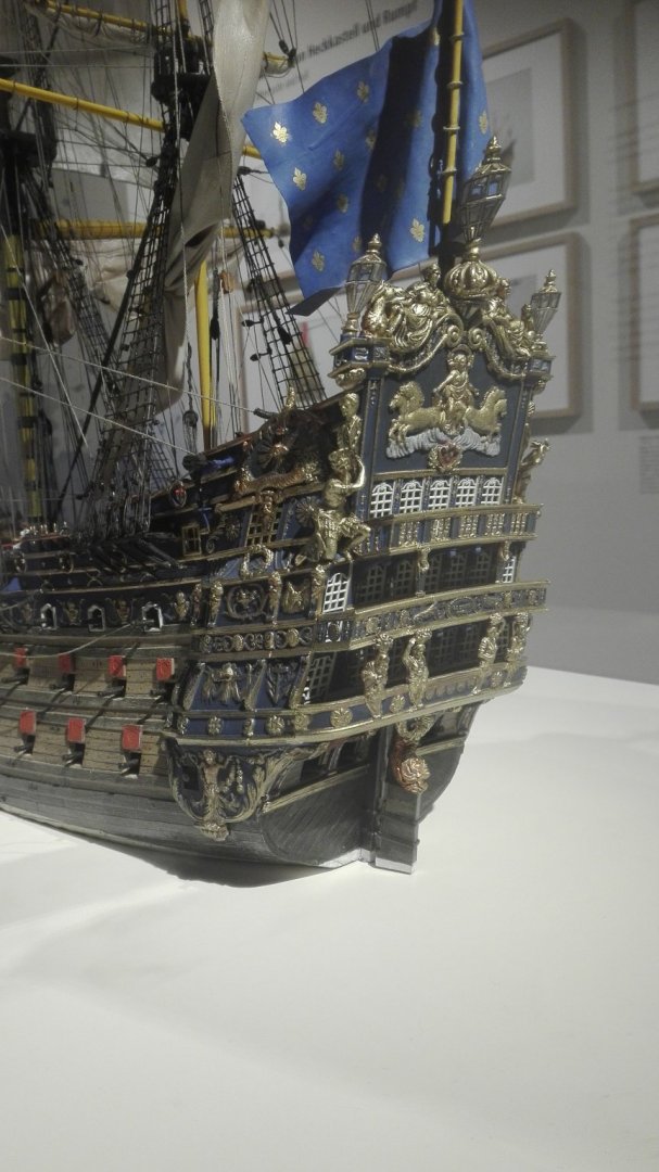
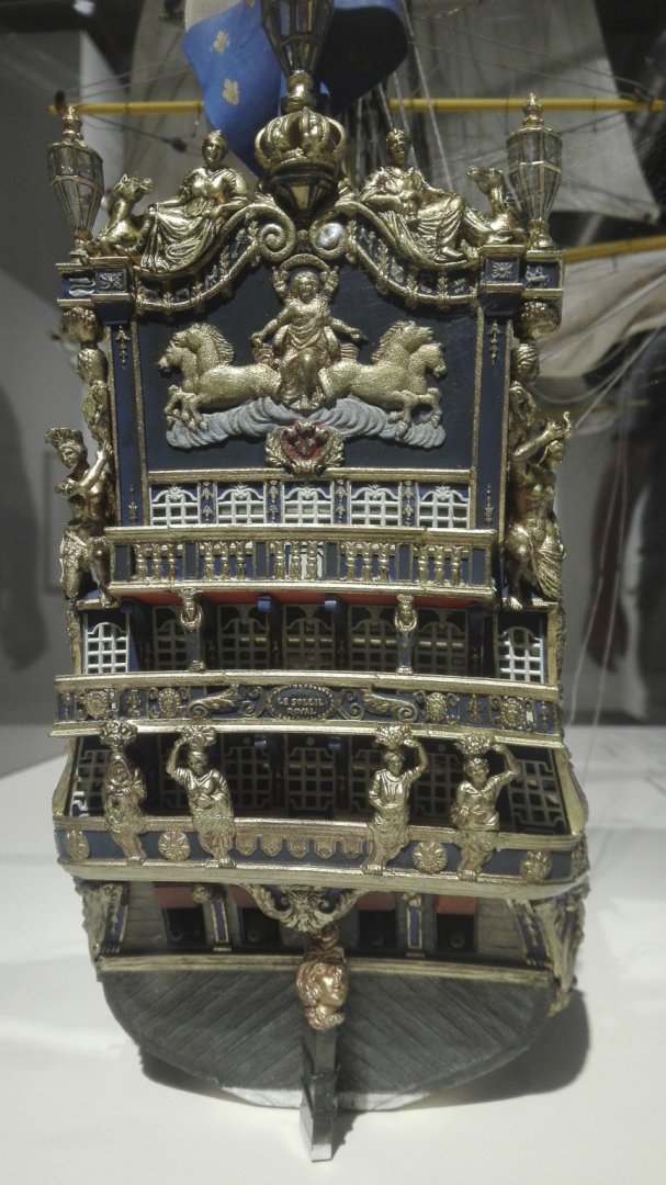
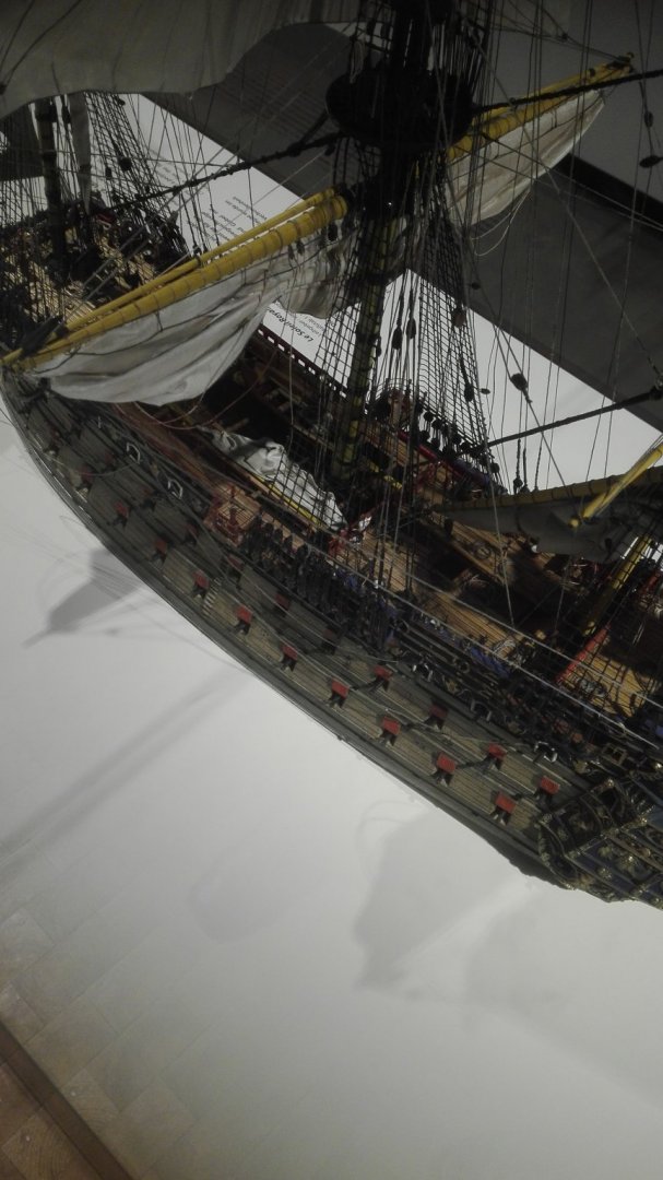
Hello Marc, yesterday I found some time tovisit the exhibition "Floating Baroque". Instead of long sentences a pile of pictures made for you and us all: All about the similarities between architecture and the decoration afloat. Scetches for an interior. Transom and SG of L'Agile. Both under gridded frostpaper - but the hights and balkonies doesn't fit!!! All three drawings... ...and SG and transom. And now comes the reason why I published my article in here and for you Marc: The circle is cut in half... The disstance between the balconies seem to be too high and the CWL is too low. The gold is not everywhere the same... This is the lend model of SR from the Collection Peter Thamm in 1/100... The starting image of the exhibition.


- 2,699 replies
-
- 6
-
-
- heller
- soleil royal
- (and 9 more)
-
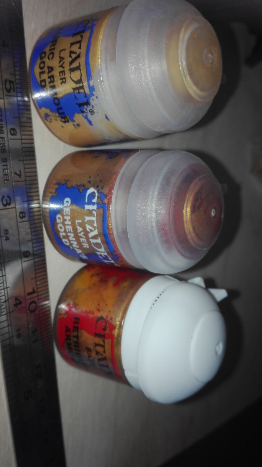
Next step is for Pirates and Dwarfs only - it is about gold! Thevwhit topped can is the basic ao what the other two shades of gold are placed onto. My personal main problem is the transom with some huge empty area where before the skull and crossed bones were located. As the skull and crossed bones were now removed and everything looks a bit lonely and lost there is deep need to change something - but how!? And as the area isn't enclosed towards the top it is not so easy to fill the picture as everything seems to be lifted towards the upper side. There it seems like a framed picture with the top bar left away for an ascension's painting. Shall there be a curved bar to enclose everything? So I think about some baroque painting to fill the empty space before the redbrown bull. So I left the survace carved as is is from the extinction of the given item and try to reuse the unflat surface for the clouds of the background. So we do start with the golden painting of the ornamentations, handrails and the little akanthus leaves.