


Doug McKenzie
-
Posts
218 -
Joined
-
Last visited
Content Type
Profiles
Forums
Gallery
Events
Posts posted by Doug McKenzie
-
-
-
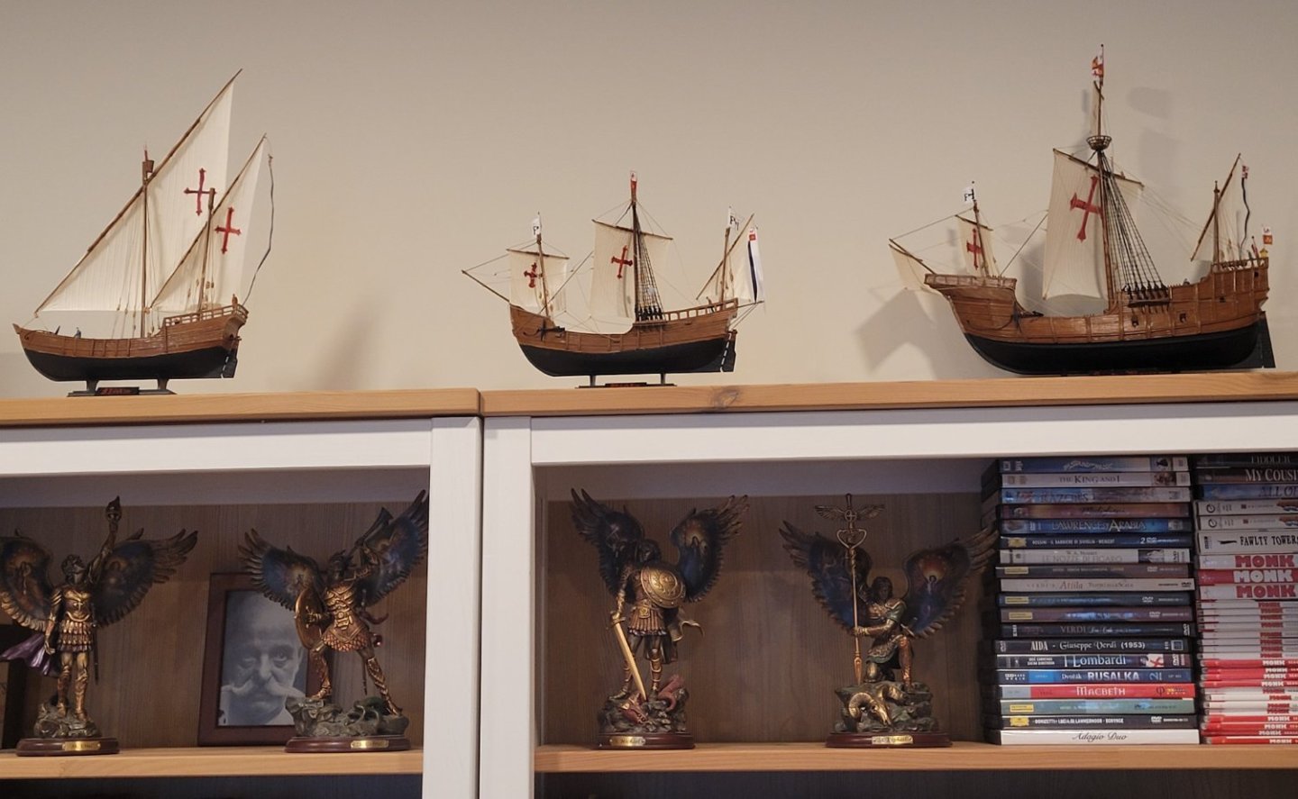
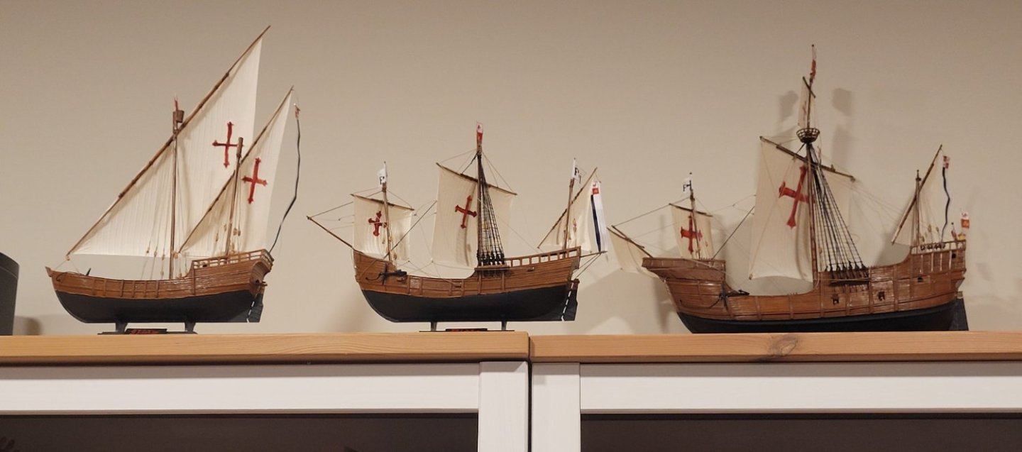
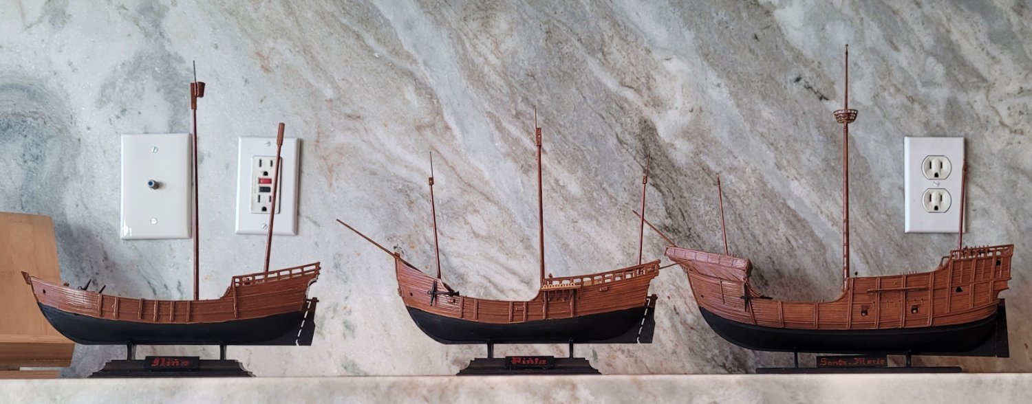
A long pause to finish the trio of Columbus' ships, Pic 1. Santa Maria is set back 14" so that it's 1:78 scale appears similar to the 1:100 scale of Nina and Pinta. These are plastic models modified to the specs of the 1966 book Columbus' Ships by Jose Maria Martinez-Hidalgo and edited by Howard I. Chapelle.
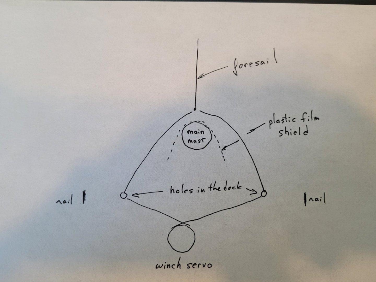
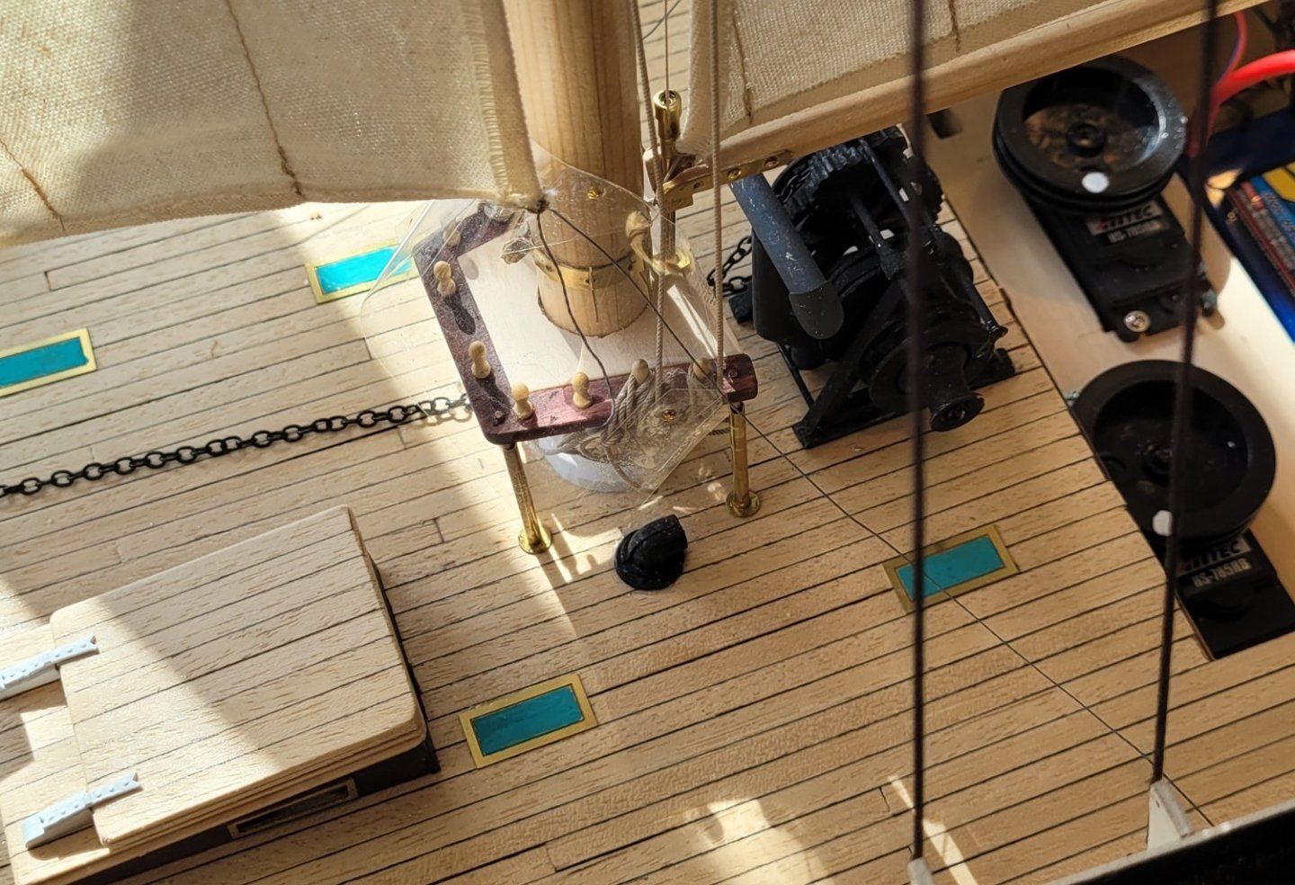
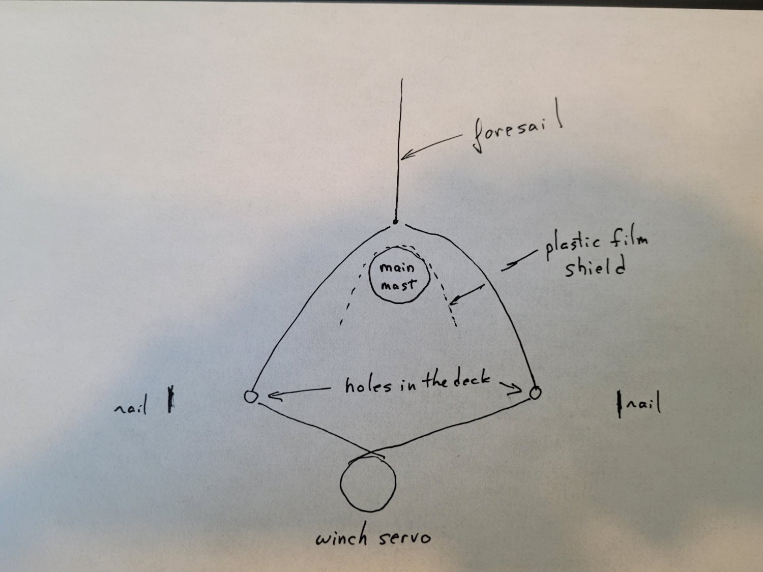
The control of the foresail sheets has been installed. Pic 2 is a diagram of the scheme. The sheets come off the winch drum from opposite directions, through holes in the deck and then to the clew of the foresail. As one side is taken in, the other side is paid out and they stay firmly on the drum. To avoid snagging, I wrapped a clear plastic film around the fife rail and tacked it to the mast and the rail. Pic 3 shows the plastic shield but not too clearly since it is transparent. You can see one of the nails (gold) that holds the top of the shield against the mast. This control scheme is preliminary because the foresail cannot be let out much for a beam reach or when running. BUT it has the advantage of not snarling. After I get some experience (remember I have very little) I will change the scheme to permit more complete positions of the foresail.
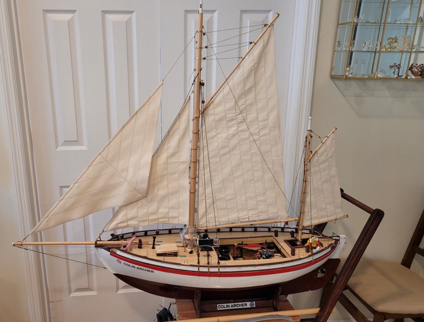
Pic 4 shows the jib. I shortened the leech a bit to bring the clew closer to the luff so that flipping over the forestay would be less likely to snag. I also put the tack of the jib on a turnbuckle attached to the slider ring so that, with the halyard fixed, the jib could be removed along with the main mast for travelling. Since there is no stay for the jib to hank onto I made the luff hem 3 layers thick instead of just 2, as with all the other hems, to support the extra tension neededd to keep the jib luff reasonably straight.
The jib control scheme will be similar to the foresail's scheme. I still have to sew the main topsail which thankfully simply follows the main..
-
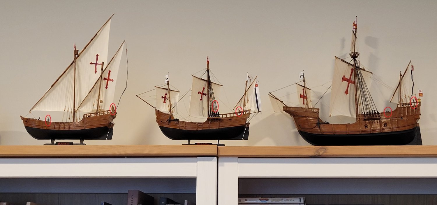
Having added 2 sailors to each ship I now post the FINAL photos! Pic 1 shows the 'official' photo and Pic 2 is the same photo with the sailors circled in red. Nina and Pinta have 1:100 figures. Santa Maria has the same figures with 2 modifications: 1) They are on little pedistals and 2) they have been dipped in varnish 5 times (like candles) to beef them up to roughly 1:78 scale.

- Knocklouder, Archi and James G
-
 2
2
-
 1
1
-
Thanks all! I just realized this morning that I haven't put any sailors on to show scale - I'll probably fix that soon.
Gregg - First I have to complete Colin Archer (radio control) for the Spring sailing season. Then I'm not sure, maybe the Egyptian boat found next to the Great Pyramid or maybe a fancy Mississippi river boat with lights and working paddle wheels and smoke and stuff or maybe something that I haven't thought of yet.
Doug
- Knocklouder and GGibson
-
2
-
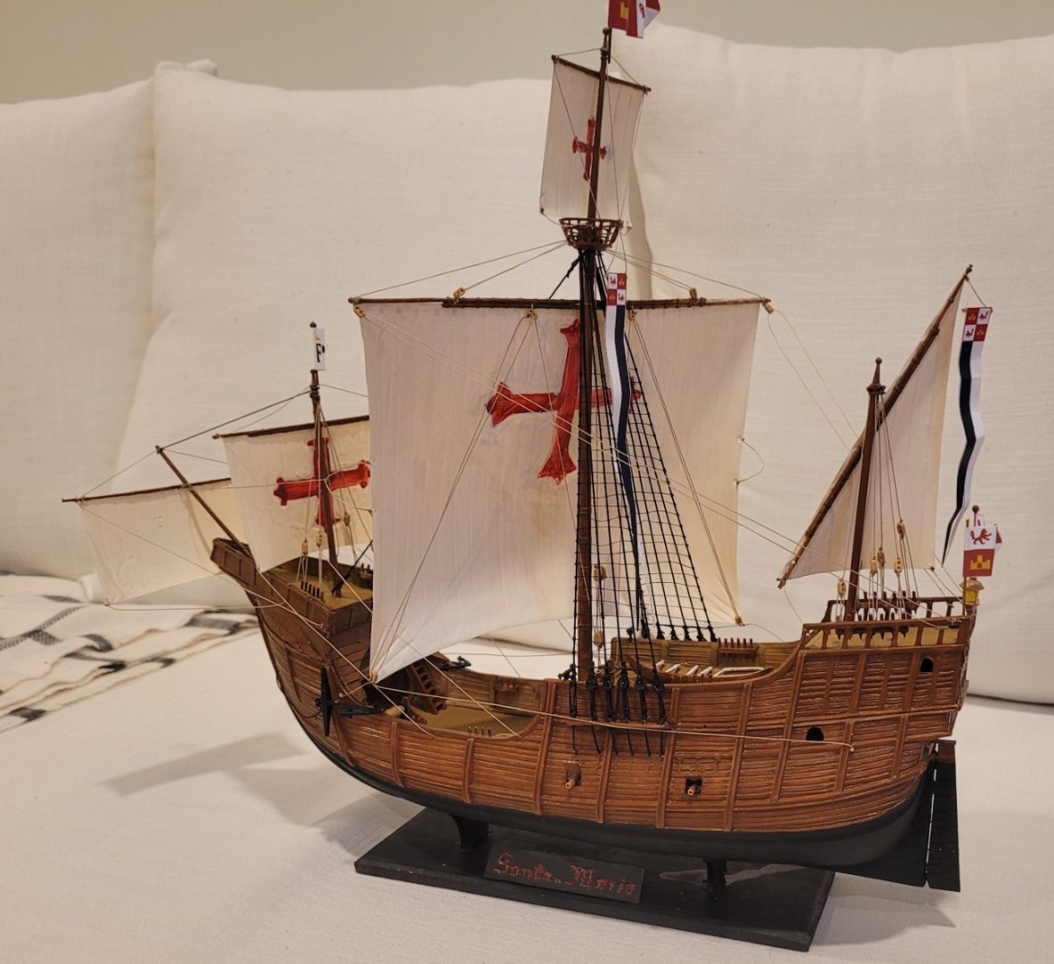
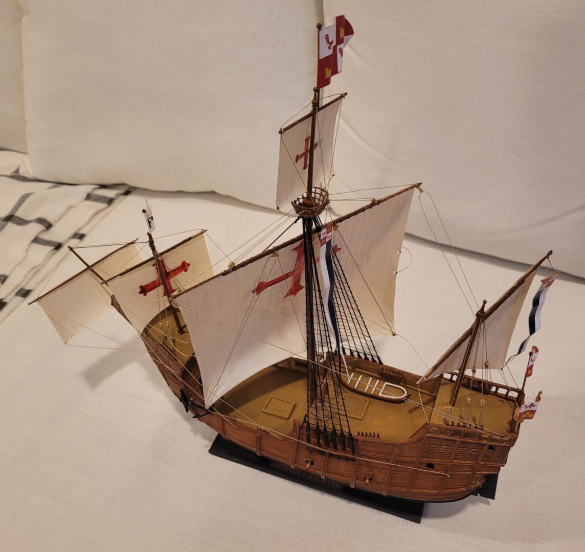
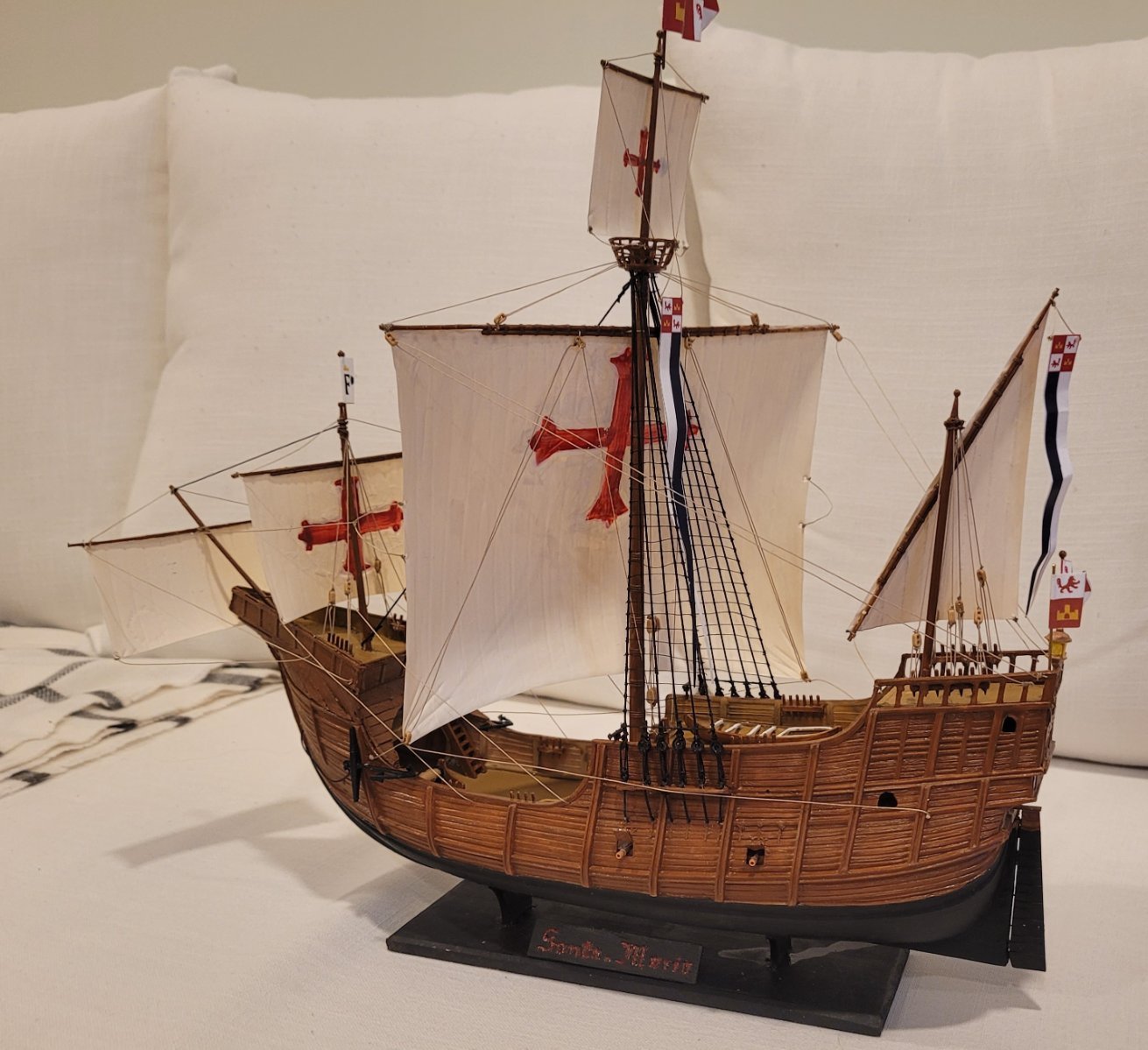
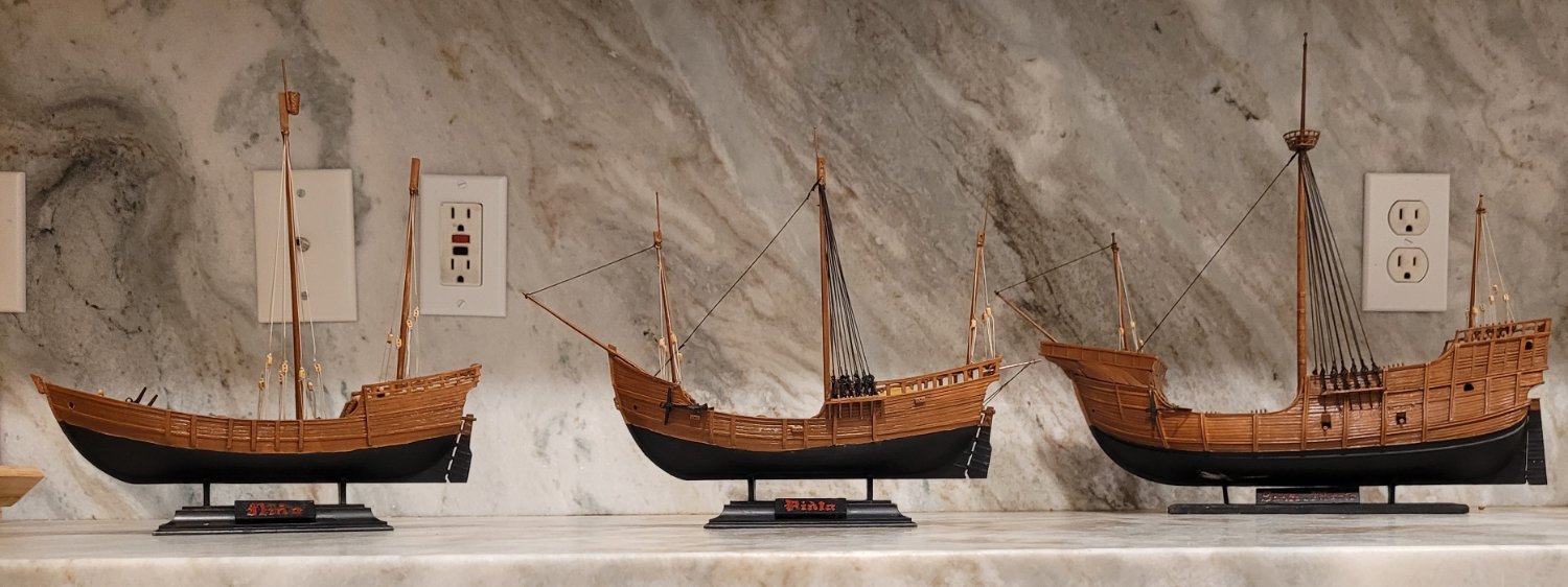
The Santa Maria is now done! Pic 1 shows her slightly aft of the port beam. Pic 2 shows her deck also. The flags seem to be pretty good, flapping in the wind, but the swallowtails hang unconvincingly - I couldn't figure out anything better.
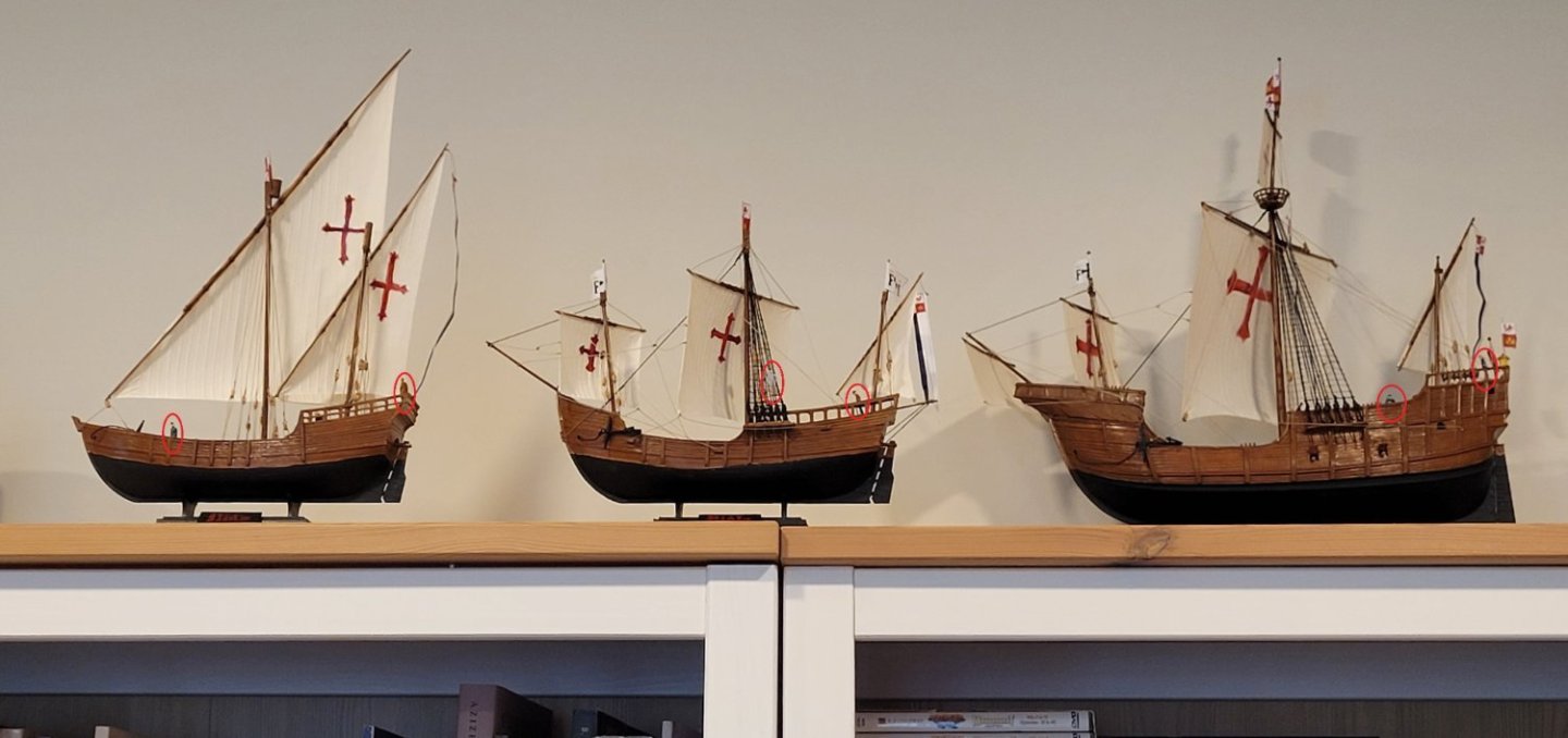
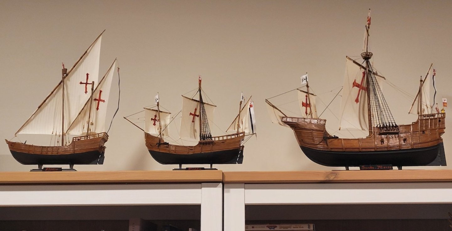
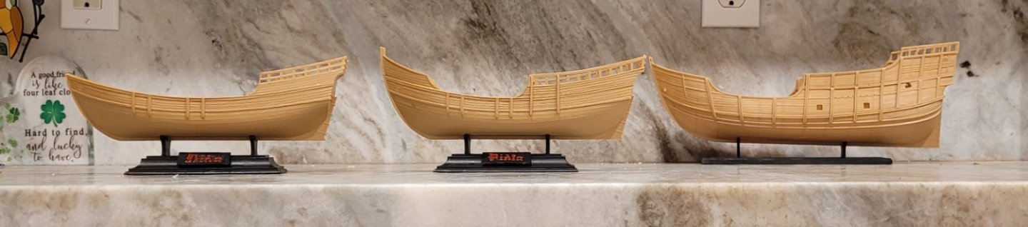
To motivate the final mounting, we first show the 3 ships in a line in Pic 3. Nina and Pinta are at a scale of 1:100 while Santa Maria is at a scale of 1:78. As a result Santa Maria is 28% too large compared to Nina and Pinta. To reduce the apparent scale of Santa Maria we move her back about 14" on the shelf and that produces Pic 4 where all three ships appear to be roughly at the same scale.
-
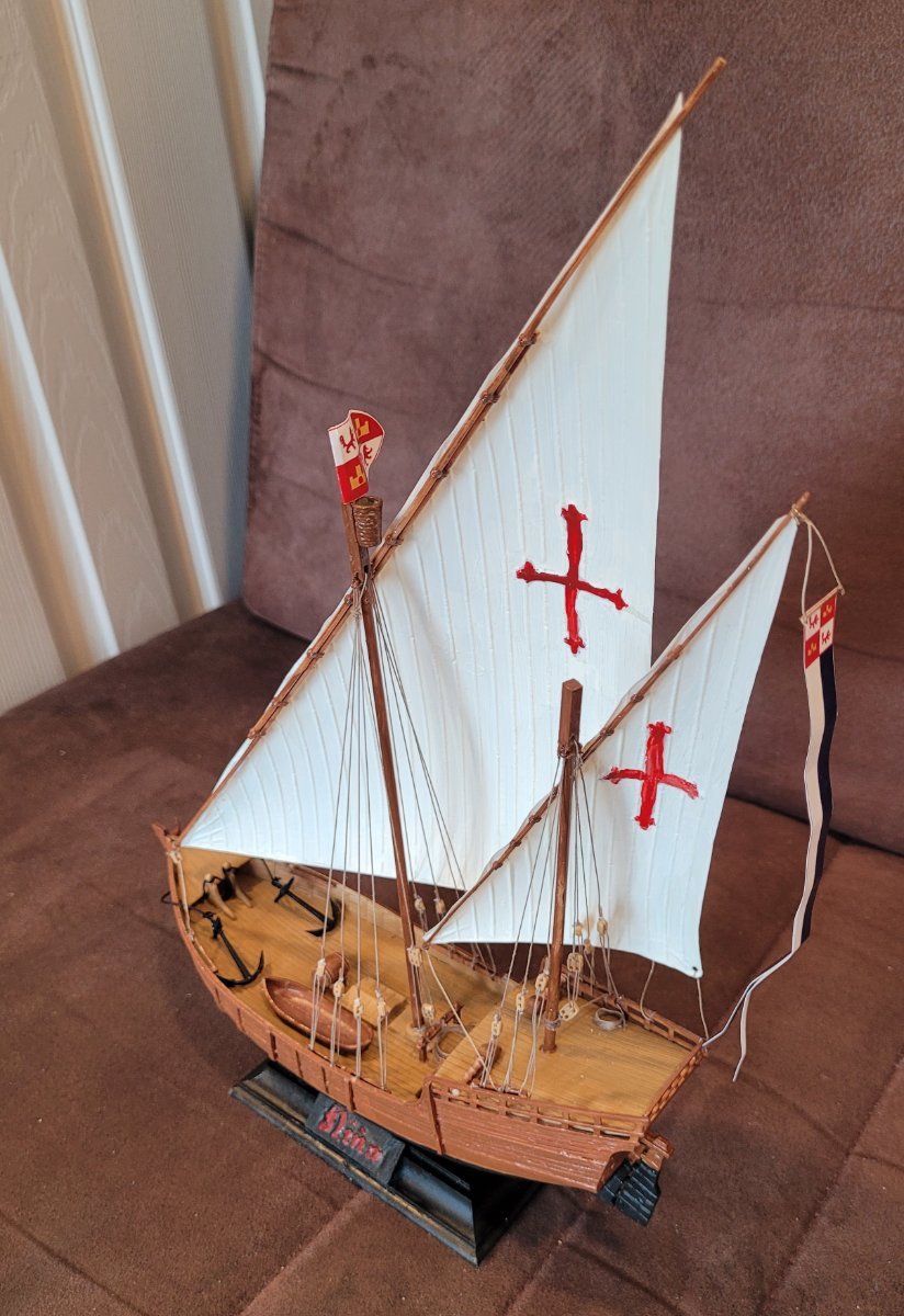
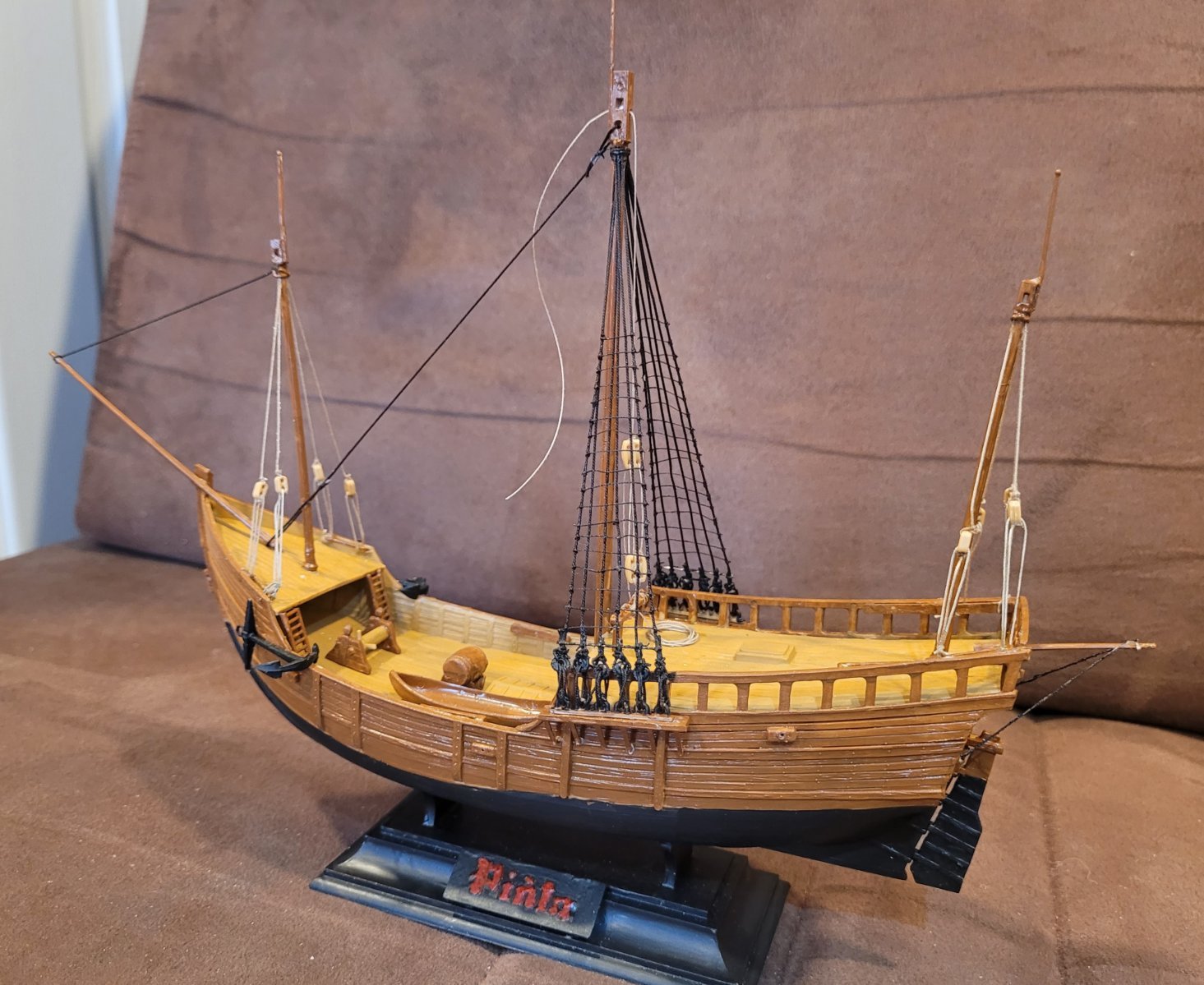
Pic 1 shows the completed Nina. In addition to the sails and running rigging, the anchor cables have been added. The mainsail's tack rides on a traveler rope. The sails are set for wind a bit forward of the port beam. Pic 2 shows the block and tackle used for both halyards. It also shows more clearly the tack rope for the mizzen sail. I think that there would have been something to limit the vertical movement of the tack as well as the horozontal movement but neither Heller or Hidalgo show anything like that.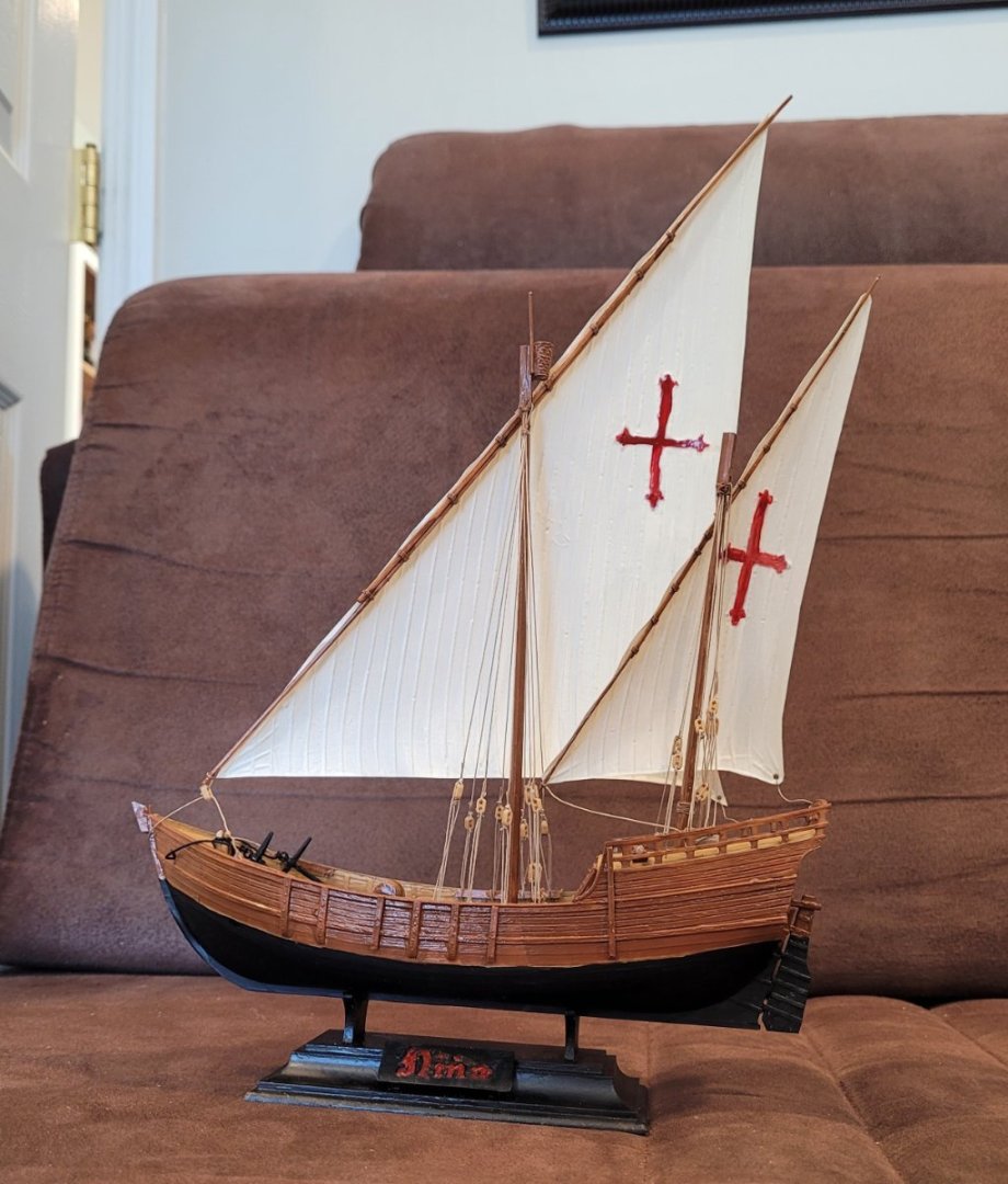

Pic 3 shows the ratlines on Pinta. I have normally put ratlines up near last but with the sails going up I figured it would be a lot easier to put them on now. Hidalgo indicates that ratlines were only used on the Santa Maria and Pinta's mainmasts - the same masts with traditional shrouds and deadeyes. The sailors shimmed up the four lateen masts and apparently the two square foremasts also as they were short. In Egypt, the feluccas are sometimes larger than Columbus' ships and yet the sailors still shimmy up, not so much the masts as the lateen yards, to furl the sails against the yards.
The scale of 1:100 is smaller than I have worked with before so I used a few simplifications on the ratlines. First, I installed sheer poles to stabilize the shrouds even though I have no evidence that sheer poles were used on these shrouds! Second, I spaced the ratlines at 16" (4 mm) rather than Hidalgo's 12" (3 mm). Third, I put them up alternately so that the first was 8 mm above the previous and then the second was put in between those two. This meant I only had to measure half of the ratlines as spacing one between two already installed was easy to do by sight. Fourth, since the shrouds were so close together, I only put clove hitches on the outer two shrouds. The result is fair in my opinion, definitely not great. Btw, I used thread at 0.006" (FS 5/8").
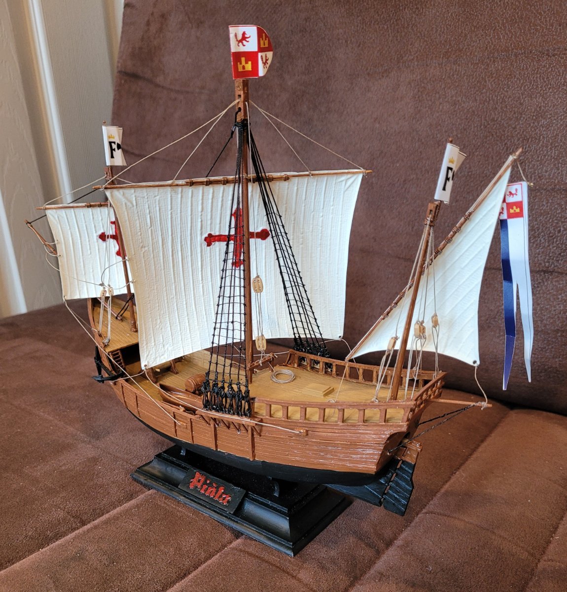
Pic 4 shows Pinta with the complete set of sails with lifts on the square yards and flags. Interesting to note that Heller and Hidalgo have near identical views of the flags and pennents. There must be good documention somewhere. On the mainsail and the foresail can also be seen leech lines that help the windward edge of the square sails keep their proper shape.
The last photo, Pic 5, shows the completed Nina with the completed Pinta. Their hulls are pretty much the same size but Nina carries 50% more sail area than Pinta.

- Knocklouder, Archi, GrandpaPhil and 2 others
-
5
-
In Pic 1, only the shrouds that use deadeyes are shown. These are the shrouds for Santa Maria's and Pinta's main masts. Hidalgo says the heart shaped deadeyes had the usual three eyes in each one. Heller provides little rings that were drilled larger to 1.5 mm to handle the several passes of the 0.45 mm lanyards (3.5 cm full scale [FS] for Santa Maria and 4.5cm for Pinta - makes no sense, but I opted for just using 3 sizes of standing rigging). For the shrouds themselves, I used 0.76 mm (diameter) for Santa Maria (FS 5.9 cm) and 0.63 mm for Pinta (FS 6.3 cm). All the minature rope comes from Syren. Shrouds were always tarred so they appear black.
I made a model ship building 101 error by finishing off the lanyards prematurely so that the mainmast on Santa Maria was sprung aft. A twisted rope come-a-long is used to bring the mast vertical and hopefully stretch the shrouds a bit so that when I replace the come-a-long with the main stay (dangling) it will not have too much tension in it.
The rings that Heller provided are small and have no grove on the outside for the shrouds so I used a little trick to attach the shrouds to the rings. Pic 2 shows the three steps of the trick. Step 1 - wrap the shroud around the ring flat on the table and dab glue on three of the four sides. Step 2 - close up the throat with the first part of a ligature knot (as shown with the heavier rope below the rings). This can also be viewed as a double overhand stopper knot before pulling it tight. Tighten the loop around the throat. Then finishing the ligature knot with a final overhand loop. The first part of this knot can cinch tightly, without slipping, while the last overhand loop is tied and a little glue applied. Step 3 - Cut the working end of the shroud off at a standard length and glue the end against the shroud as if seized to it. I use these double overhand loops, to tightly cinch without slipping, in all sorts of applicatons.

The remaing 6 masts are supported by runners. Hidalgo says that the 4 lateen masts (all 3 mizzens and Nina's main) do not have shrouds rather they only have runners - I imagine he means 'running backstays' or 'running shroulds' (allthough I've never heard this later term). He gives no explicit information about the Santa Maria's or Pinta's foremasts supports but his diagrams indicate runners also. The runners are all running rigging so they were not tarred and appear tan. The blocks used for the runners are not all lined up neatly the way the deadeyes are. I remember hearing, on a trip to Egypt years ago, that the runners on the lateen masts (on the fellucas) were tightened and loosened at different times which probably explains why they didn't all line up. The forestays and mainstays on Santa Maria and Pinta are installed to balance the associated shrouds and runners. Hidalgo specifically says that Santa Maria's main topmast has no support at all - it doesn't need any because the topsail is so small.
 In the next post, the square yards, the lateen yards, the sails and the running rigging will be installed because they are most easily installed together. Adjustments to match Hidalgo will be discussed.
- Archi, GGibson, Knocklouder and 1 other
-
4
-
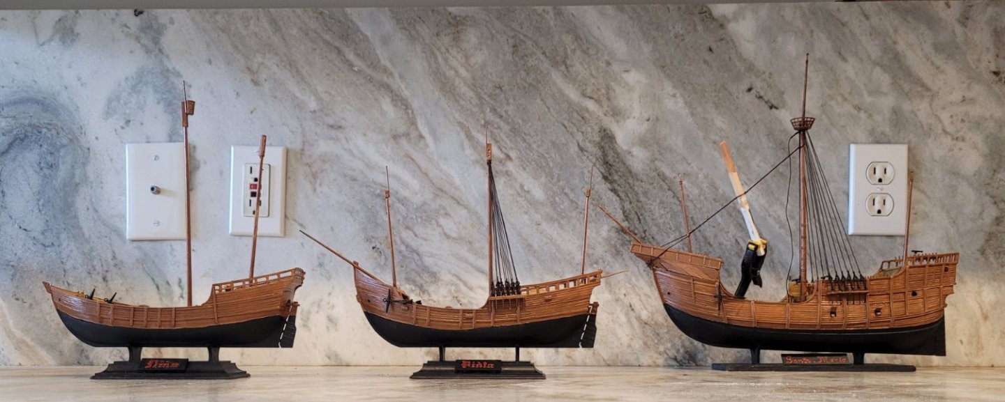
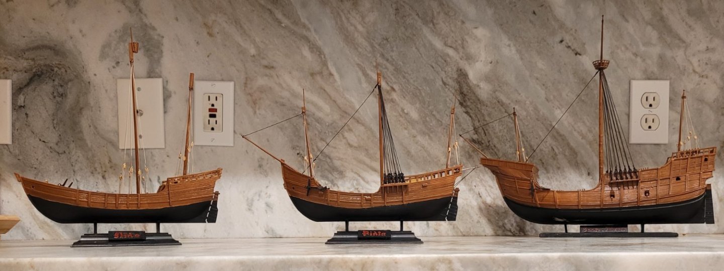
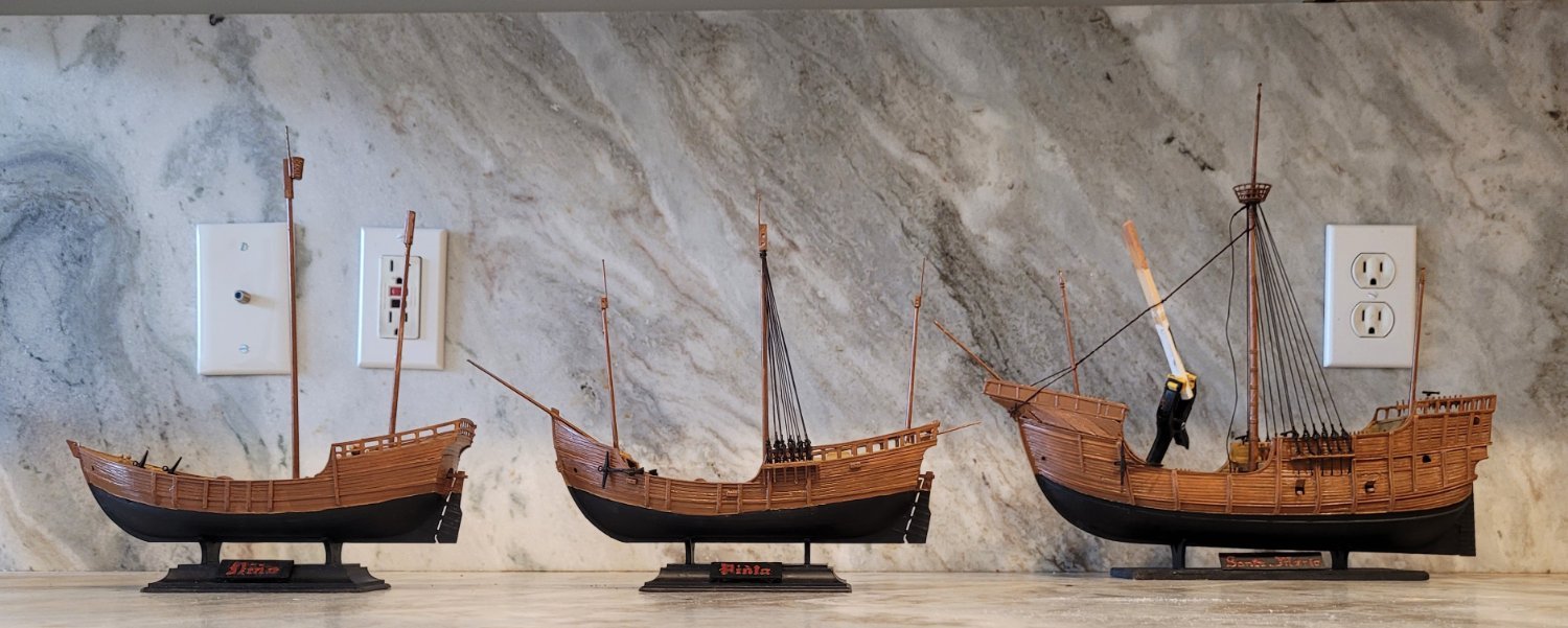
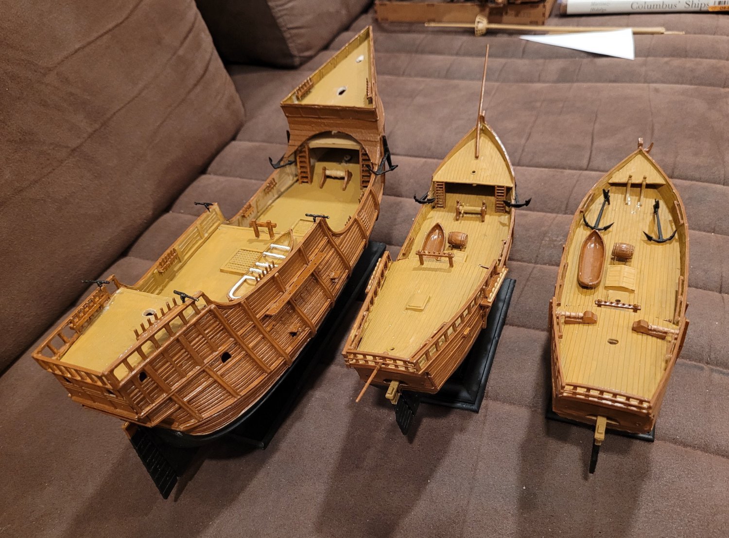
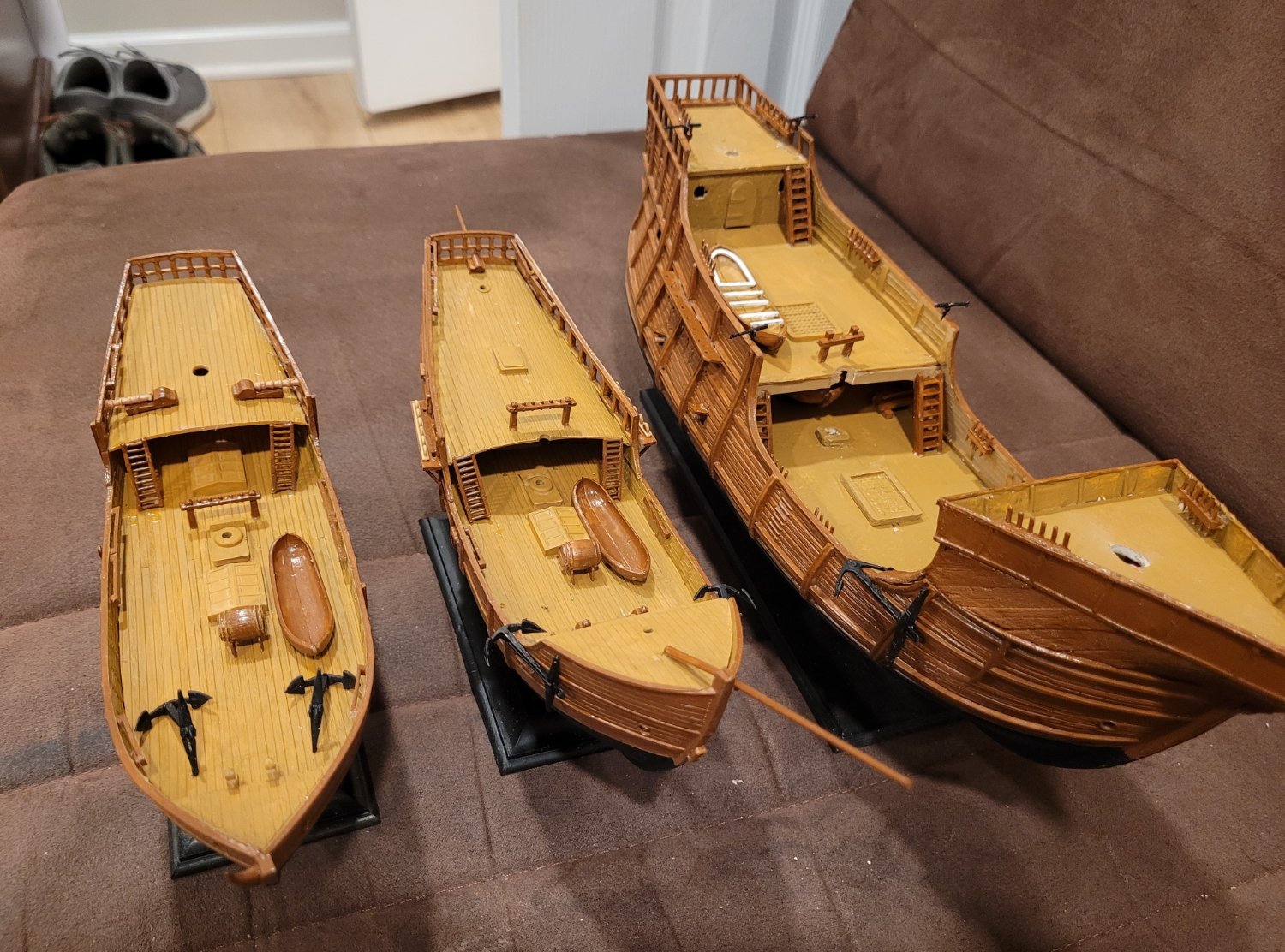
Pic 1 shows the 3 hulls with all their fittings on viewed midship forward. Pic 2 is the same but viewed midship aft.

Next, we'll show all 3 ships with their masts stepped discussing the modifications that have been made to implement Hidalgo's mast dimensions and locations as best we can. This is also a good time to compare 19th century American and British masting practices with late 15th century Spanish and Portugese practices.

Santa Maria
First, we compare the mainmasts. 1) Heller's Santa Maria mainmast has pretty much the same length as Hidalgo's. 2) The diameter at the partners, however, is only 85% as big. I'm guessing that the full diameter looks too fat to the modern eye so Heller reduces it somewhat. In the 19th century, a mast the same length would have been even skinnier, about 75% as big in diameter as Hidalgo's. 3) Interestingly, the taper of Heller's mast (diameter at the hounds / diameter at the partners), 57%, is about the same as Hidalgo's, 62% whereas in the 19th century, there was less taper at 75%.
Second, we discuss the mast rakes. Heller follows Hidalgo closely with mainmasts being vertical, foremasts having a slight rake forward and mizzen masts having rake aft. By the 19th century, all masts raked aft with the least rake forward and the most rake aft.
Third, the foremasts and mizzen masts. This discussion needs to include the sails since they are affected by changes in the masts. As with the mainmast, Heller's mainsail is in good proportion to Hidalgo's. However, both the foremast and the mizzen mast had to be shortened to about 70% of Heller's height to match Hidalgo's and this directly effects the sail's heights also. The sail area of the foresail is reduced to 70% but the area of the mizzen is reduced to about 50% of Heller's original because it is a lateen sail and the foot is reduced by 70% as the height is reduced. The mizzen mast also had to move forward so that the sheet of the mizzen sail can be taken to the taffrail since Hidalgo does not support Heller's boomkin. Hidalgo points out that the mainsail of a nao is by far the main contributor to the speed of the ship; the other sails are mainly for balance to aid in steering.
Pinta
The main and mizzen masts as well as the bowsprit were fine but Heller's foremast needed to be shortened to about 90% of the original. Hidalgo does not give info on mast diameters for Pinta or Nina so we cannot make any comparisons.
Nina
Both main and mizzen masts of Heller's were in good proportion to Hidalgo's.
The next post wil show the shrouds of the three ships.
-
Bruce,
For starters let me say that that is a lovely model that you working with. I am not striving for the same level of accuracy that your's has especially in the area of the sails and the running rigging. I am aiming for the impression of authenticity with a lot of simplicity to make operation easier. For example, my main throat halyard belays on a pin on the fiferail and is glued - there is no coil. The peak halyard, on the other hand, belays and coils because I want to be able to demonstrate skandalizing. I have left off all sorts of lines such as tacks and outhauls because I never plan to use them. As a result the fiferail around the mainmast is relatively bare and less likely to hangup the staysail sheets.
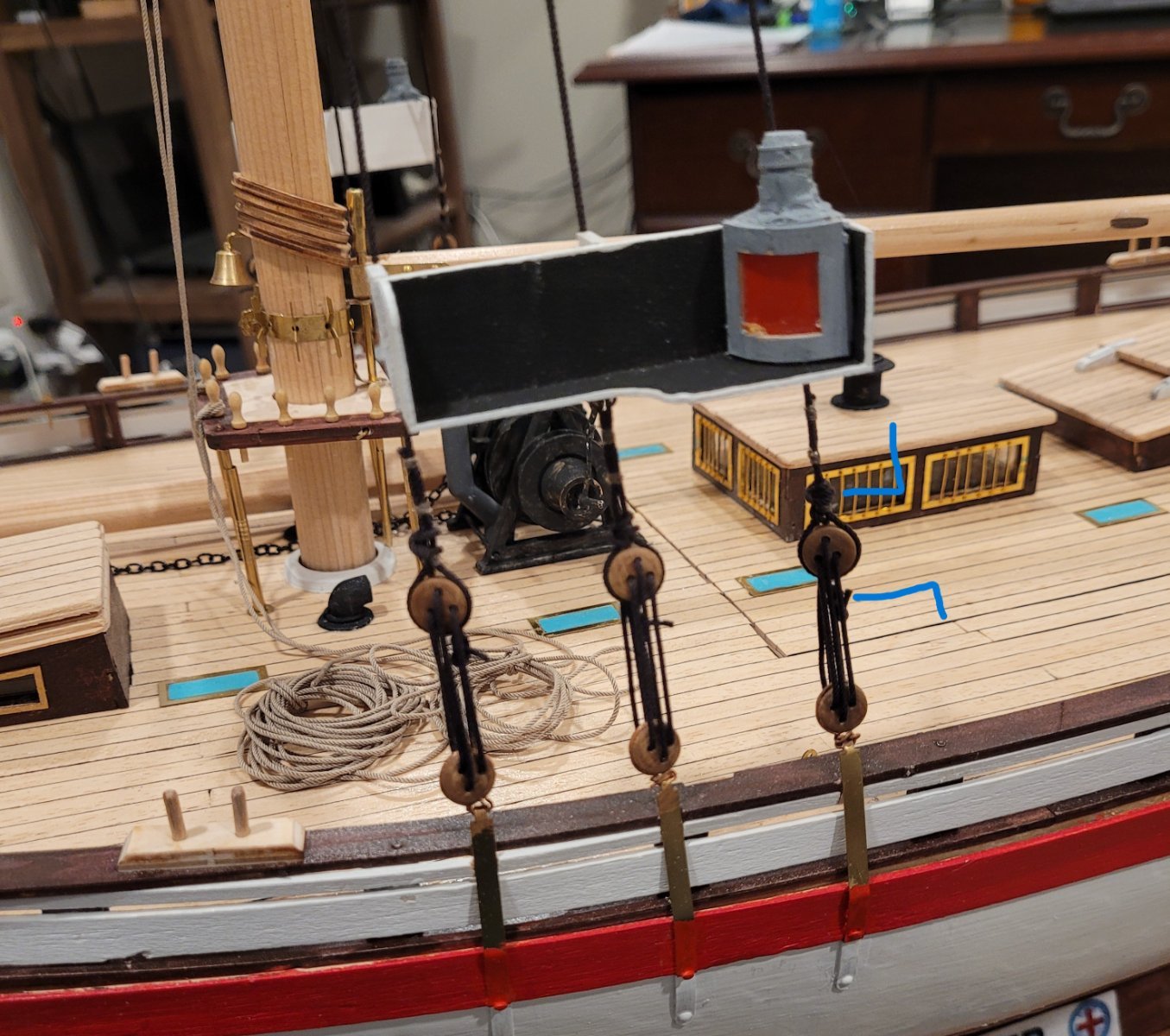
None of the sheets (except the mizzen because I don't control it) are correct. They are all single lines - again to minimize fouling. You asked specificaly about the mainsail and the staysail. The mainsail I described in post #50 which you have seen cause you reference the little eyebolts. There are two components - 1) the loop driven by the winch servo and 2) the actual sheet which is attched to the loop. Note there are no blocks used on the main sheet - I sacrifice authenticity for convenience. I have yet to try this out this single sheet arrangment on the water and won't until the spring. My objective is to avoid fouling the sheet. The truth will emerge in the Spring. I am about to implement the staysail sheet control which I will describe in my next post. This uses its own winch servo. This will be a two sheet arrangment (port and starboard) where the winch pays one sheet out as it pulls in the other. I'm doing this because I want to be able to backwind the staysail. By keeping the fife rail pretty clear and by cutting the staysail foot a little short so that the clew moves a little forward of the fife rail I'm pretty sure there won't be a fouling problem.
As far as "lipo batteries, with brush-less motor" I am a neophyte with radio control and I just do what I've been told to do as far as the equipment goes. You may enjoy a look at post #34 where I describe how I selected the various pieces of equipment.
Good fortune as you try to maintain authenticity while doing RC. I have so little experience I don't even know how other modelers strike their balances.
Great to hear from you!
Doug
-
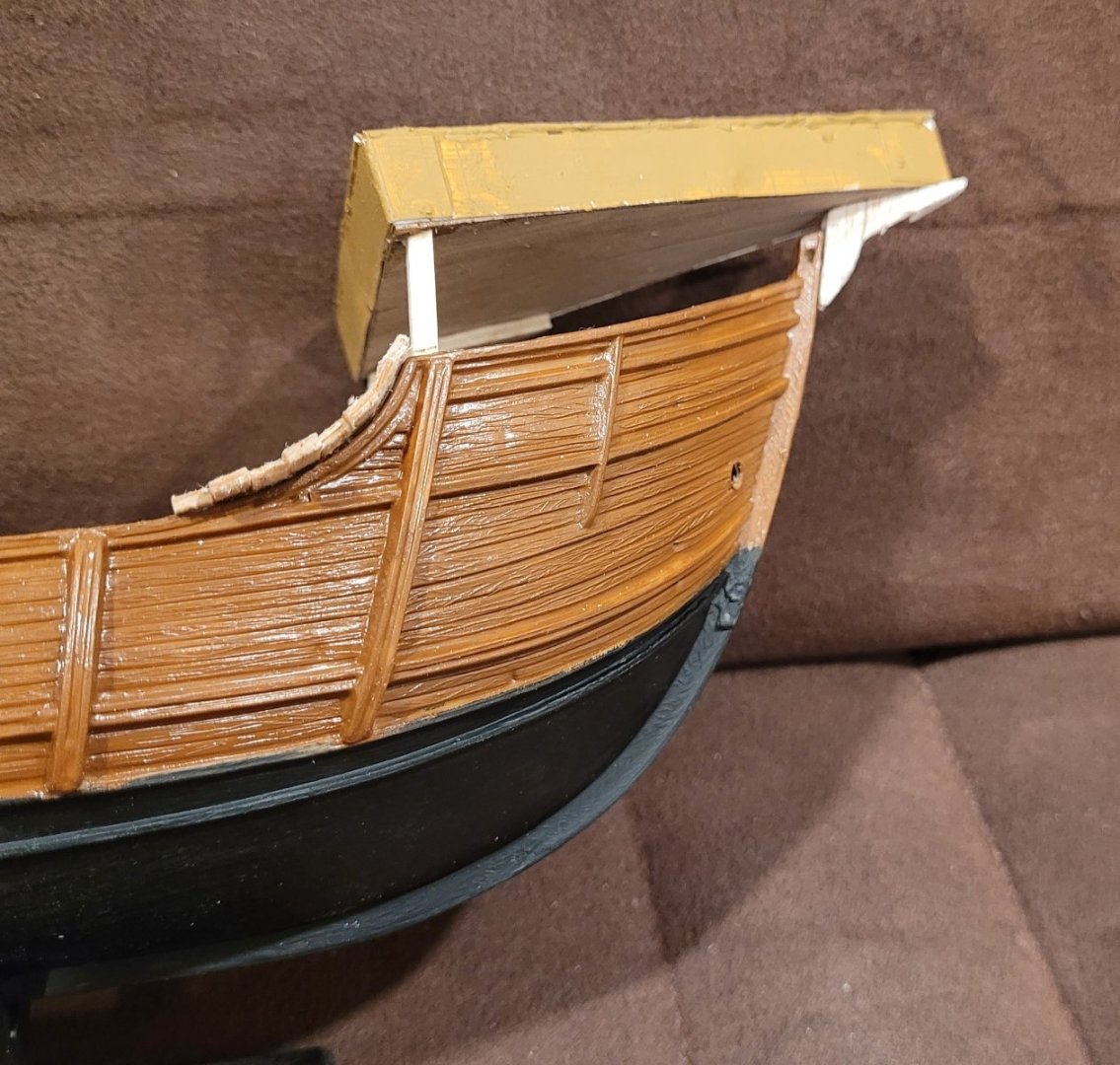
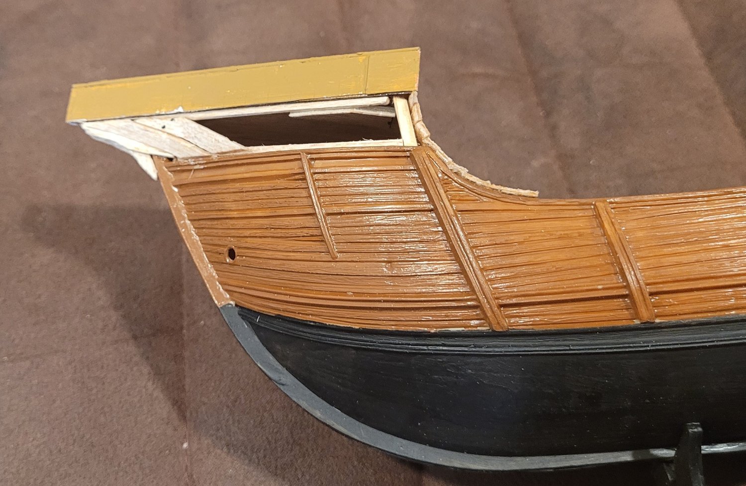
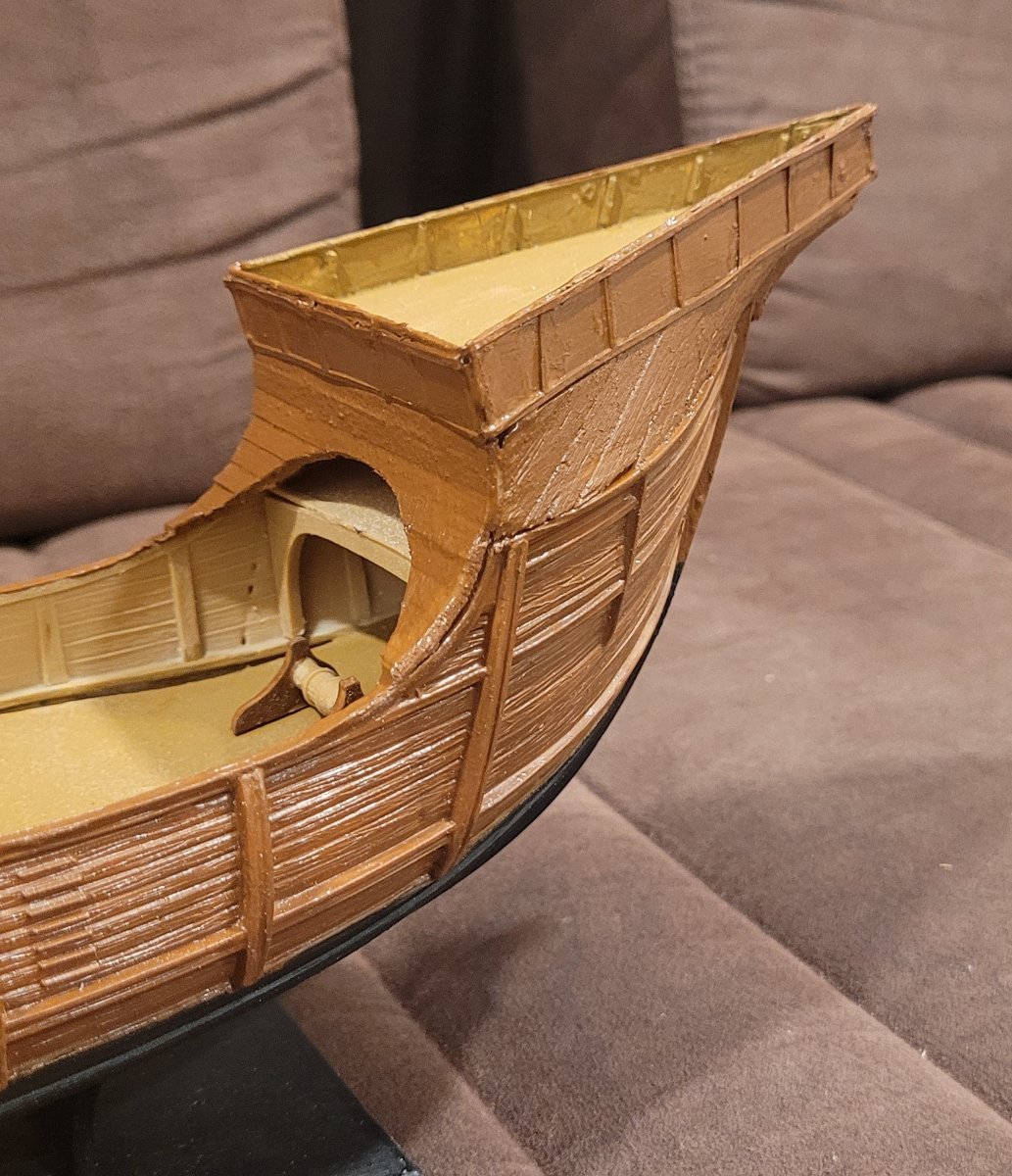
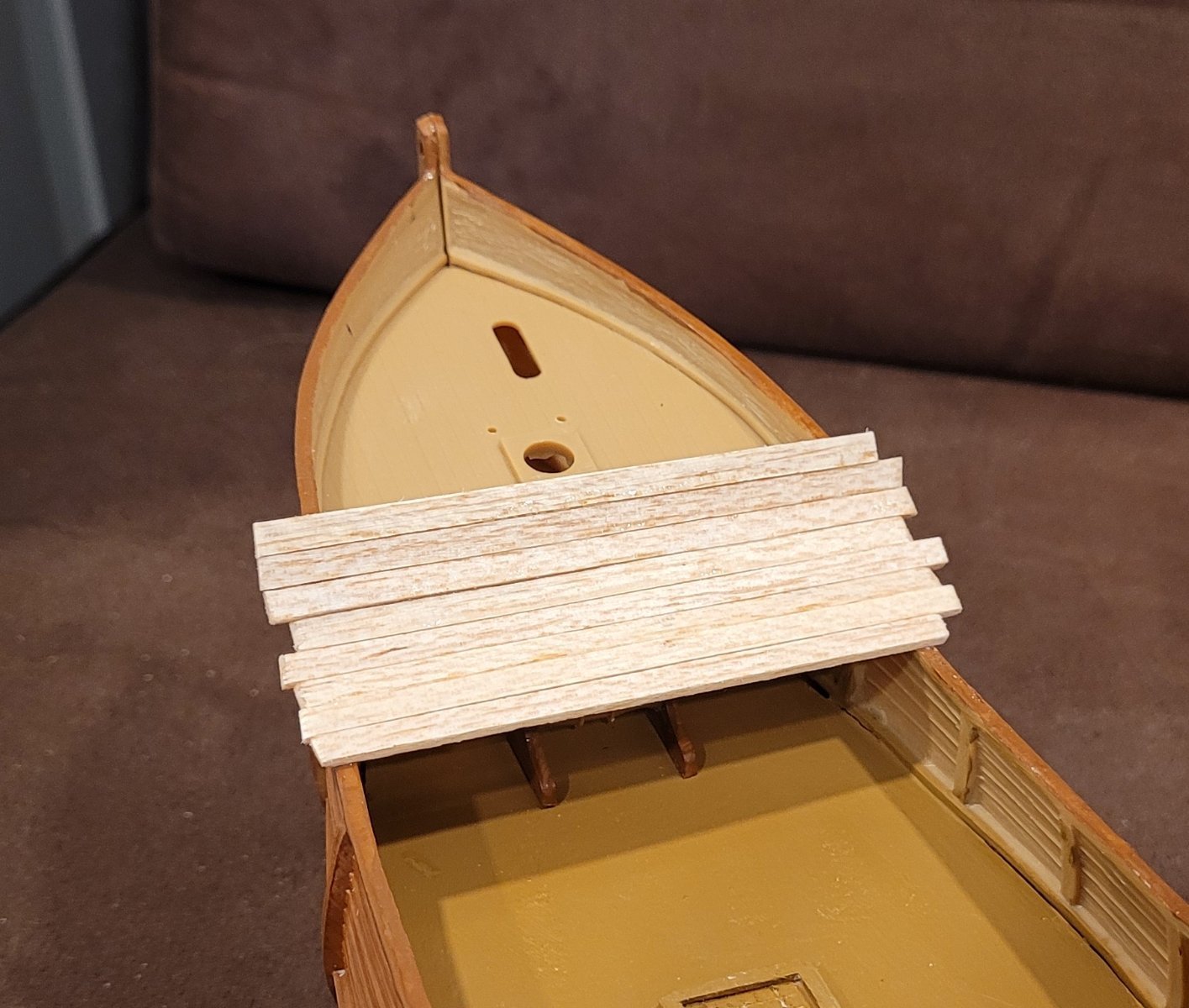
Now we proceed to complete the raised fo'c'sle. Pic 1 shows 3 of the slanted planks that connect the raised fo'c'sle to the top of the caravel bow. Hidalgo clearly shows this slant but it wasn't clear to me why it appears. The combination of the platform overhanging the stem and starting the planking at the bow induces the slant.. Pic 2 shows the completed planking.
Pic 3 shows the panel borders which sort of mimic the open rail at the stern. The large arch is seen in this Pic also. There are no hints as to the purpose of this planked surface with an arch in it. Pic 4 shows the completed platform after being coated with whale oil and fish oil. At this point, I can say that how the decks were treated is not described. Heller uses a tan to represent that unknown treatment.
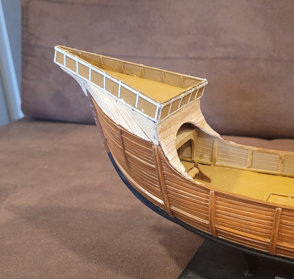

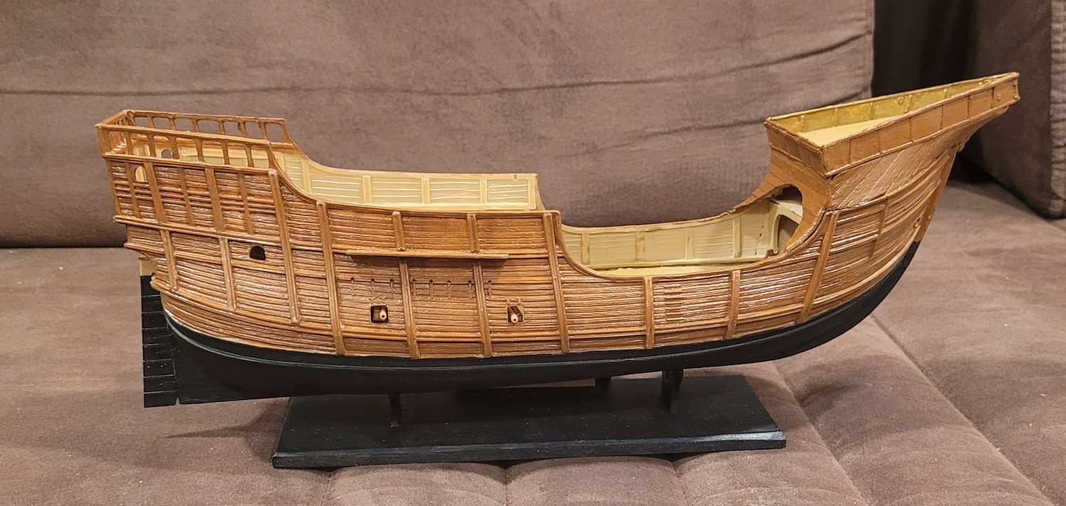
Pic 5 shows the whole ship with the completed bow platform.

- Papa, Knocklouder and GrandpaPhil
-
3
-
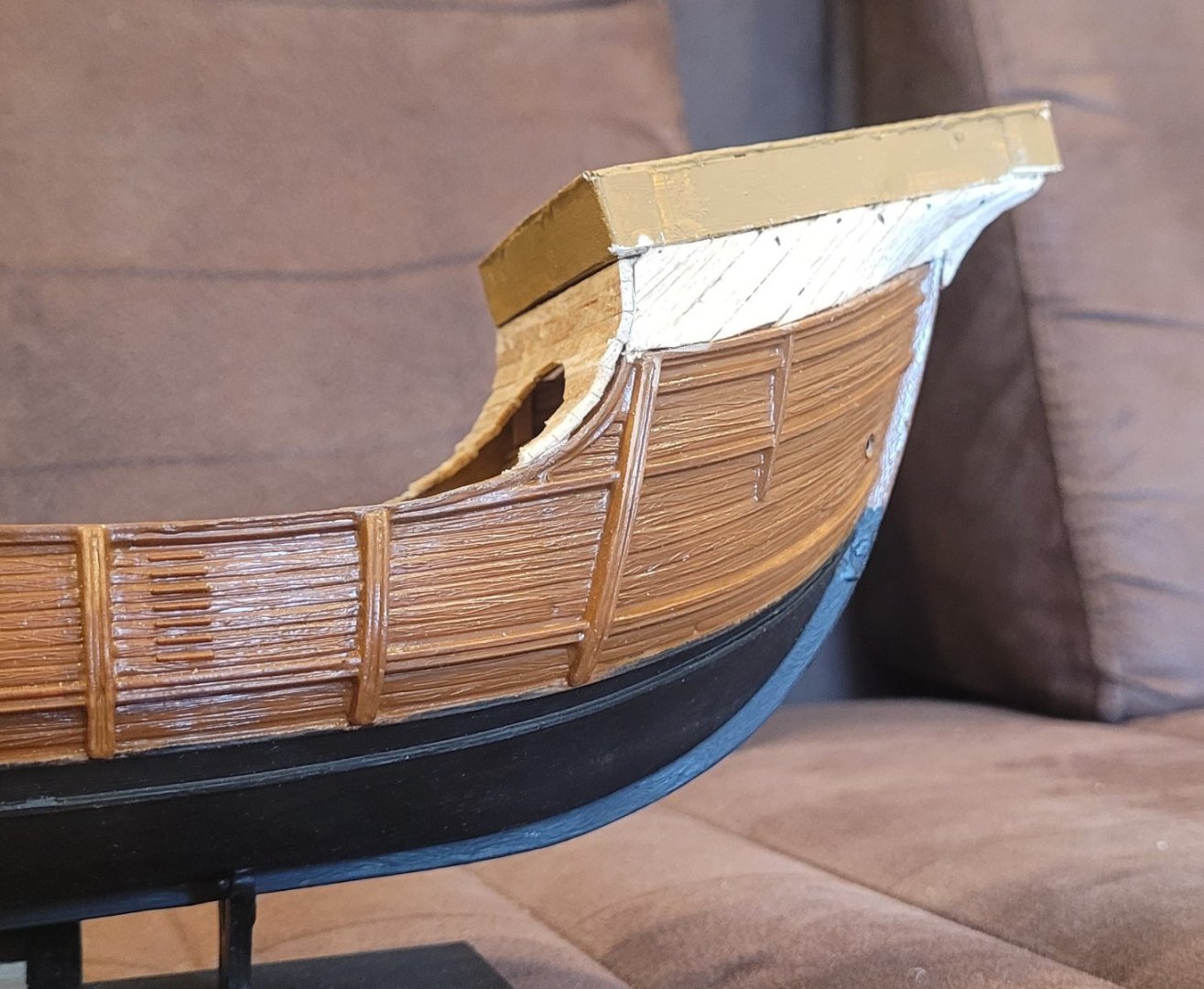
In this post, we will discuss how the high fo'c'sle is added to Heller's caravel type bow for Santa Maria to acheive the true bow form of a nao that Hidalgo describes. It is clear from diagrams and models of the nao that this high fo'c'sle was indeed added on top of a caravel type bow. I therefore assumed that it would be clear HOW to add the high fo'c'sle. I did not find this to be true however. As a result, I have used a tried and true method of construction that I call 'build-whatever-is-easy-to-understand-first-and-then-maybe-you'll-see-how-to-do-the-rest'. Pic 1 shows the bow of Heller's Santa Maria in an almost completed state (from Heller's point of view). There are two components of the high fo'c'sle which are easy to understand.
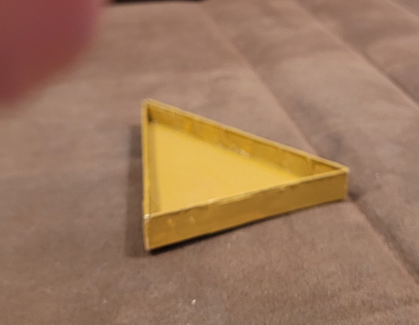
The first is the actual upper platform. Pic 2 shows our construction of this upper platform. A thin piece of plywood forms the triangular deck. 3x5 card is used for the railing. 1mm rod is used for the rail cap as well as the stanchions. The platform is painted the same color as the decks and inner faces of the bulwarks - even though it doestn't look like that. Having made the platform, it has started to become clear how to attach it to the caravel bow.
The other component which is easy to understand is the flat planking on the after surface of the fo'c'sle which follows from the waist up the curve of the bulwark all the way to the bottom of the upper platform. It is not clear, however, how this planking was done because there is a large arch in the planking that roughly follows the arch in Pic 1. Pic 3 shows the first step of creating this curved bulkhead with an arch. I'm pretty sure my method does not reflect common practice but I simply couldn't come up with a better method. The lowest plank is actually glued to the top of the bulwark railand will be scrapped when this curved bulkhead is completed. The both rails above that plank have been vaselined. The succeeding planks are edge glued to the preceeding plank. This planking will proceed up to the upper platform when a structure is built to support the upper platform. This planking needs to be removed so that the back can be strengthened before the arch is cut out. I could have fashioned curved frames to mount the planks on but that seemed to be quite difficult which is why I went this way. In Pic 4 the platform is supported by 2 pillers aft. How the horozantal planking will be finished is now clear with the 2 pillers waiting to support the remaining planks. Here, the color similarity is clear.

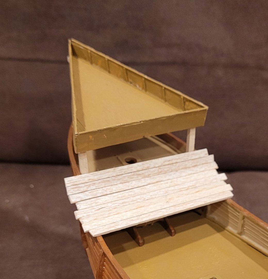
Pic 5 shows the forward support for the platform and also the remaining engineering challenge which is how to plank the space between the top of the caravel bow (curved) and the bottom of the platform (straight). Traditionally, this is filled in with practically vertical planks which I can emulate with some strip stops on the bulwark rail and the bottom of the platform to which the ends of the planks will be attached.
- GrandpaPhil and Archi
-
2
-
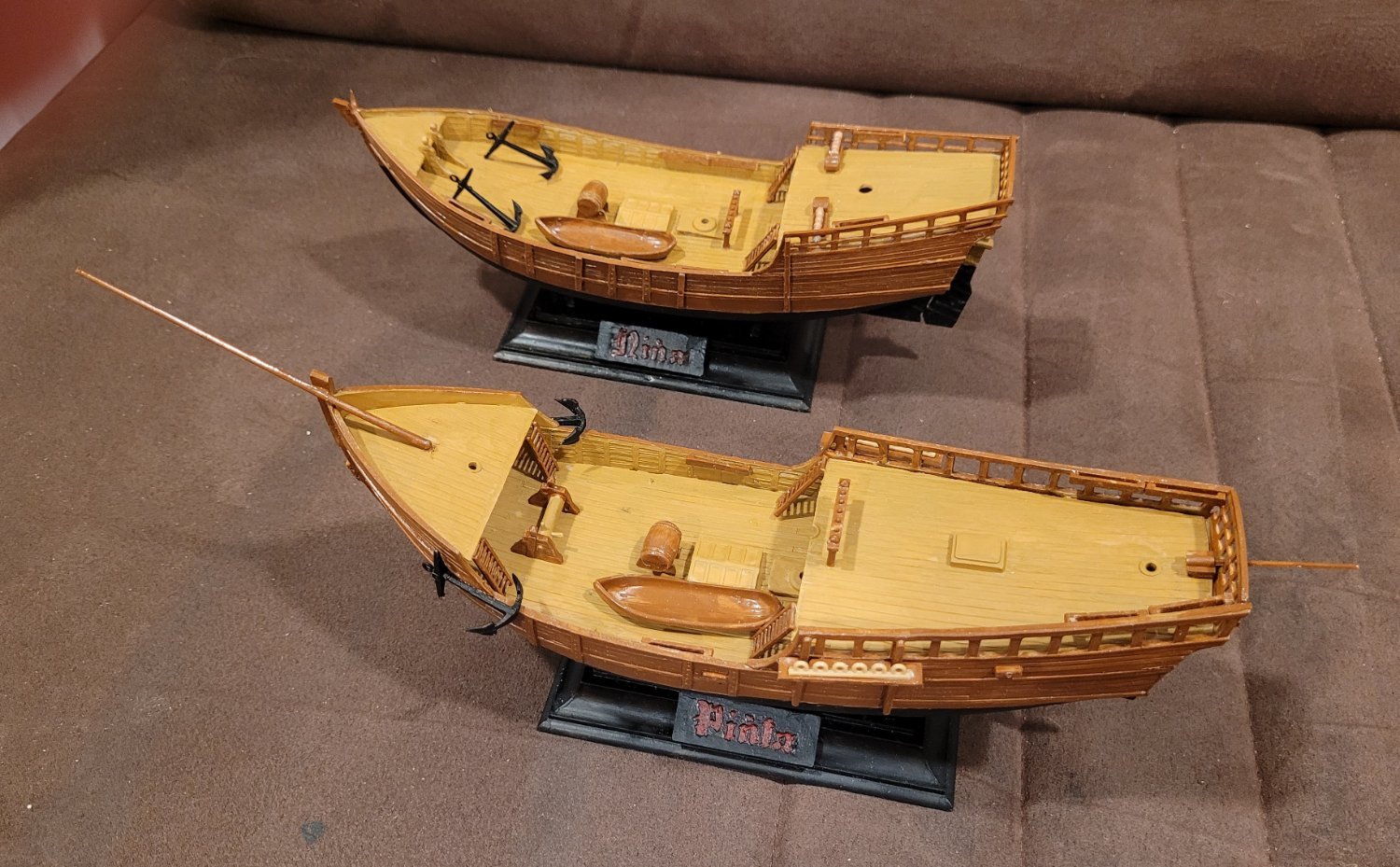
The deck items for Nina and Pinta are complete , Pic 1. A couple of notes are in order relative to bringing Heller closer to Hidalgo.
Heller has the anchors stowed on deck for both Nina and Pinta. The problem is that Pinta has a much shorter deck than Nina due to its larger fo'c'sle and its much larger quarterdeck. There is scarce room for the anchors. The solution came from a photo of a Santa Maria model built to Hidalgos specifications showing the anchor hanging off the bulwark just aft of the fo'c'sle as shown in Pic 1 for Pinta.
Also, Heller has a boomkin for Nina's mizzen sheet but Hidalgo does not so it has been left out. This makes sense when you note how much further forward Nina's mizzen mast is than Pinta's.
The 2 cannons on Nina's quarter deck, called lombardas, have a fixed elevation. Hidalgo shows how they are mounted on the carriges with an elevation which neutralizes the steep camber of the quarterdeck so that if the ship is not rolling the cannons point horozontally. The ship has to roll to change the elevation of the cannon!
A note about painting. The underwater portions are black (see Nina's rudder) because the bottoms were coated with tar and tallow. The topsides were treated with whale and/or fish oil. Heller distinquishes beteen the dark brown topsides and the light brown deck. Maybe that is significant and maybe not!

- GrandpaPhil, GGibson and Archi
-
3
-
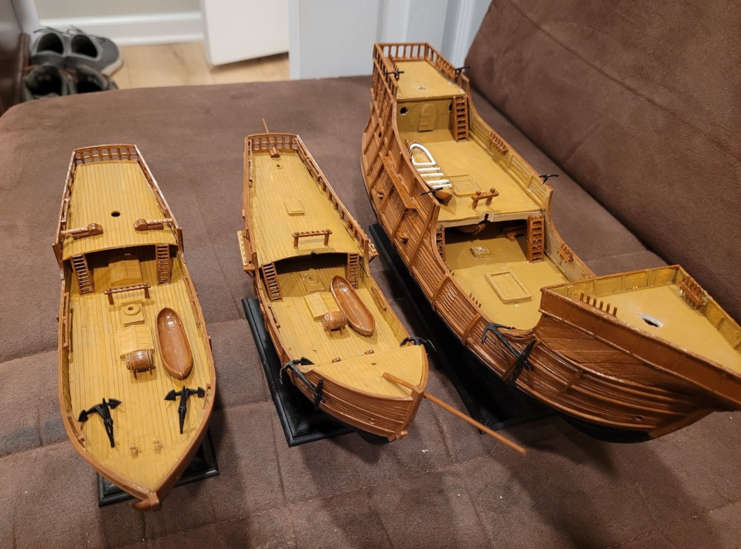
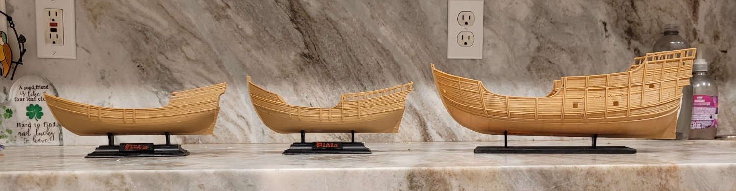
In this post, we'll show how we will neutralize the different scales of the nao (Santa Maria) 1 to 78 and the caravels (Nina and Pinta) 1 to 100. In Pic 1 the trio is shown lined up with each other. The Santa Maria dwafs the two caravels inappropriately because the scales are different.
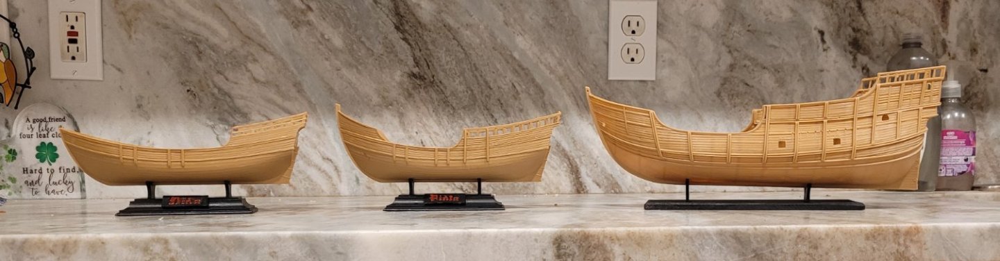 In Pic 2, the Santa Maria has been pushed back about 14" so that she is on a parallel course to the caravels but displaced from their course line. Letting the caravels remain at a scale of 1 to 100, the scale of Santa Maria appears to have been increased from 1 to 78 up to 1 to 95. In the actual placement, where the hulls will be displayed, the apparent scale will probable be a little less.
Well, I have disappointing news. I started to make the changes to the stern upper profiles of Nina and Santa Maria and it became apparent that it would ruin some of the clean sweeps of the wales and planks so I have decided to leave them as is. I still take pleasure in the technique of equalizing the scales of the nao and the caravels, though.
-
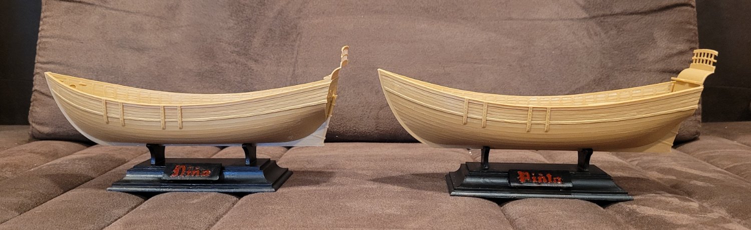
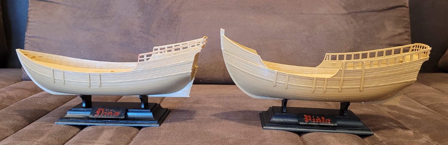
Having fessed up to a serious mistake, I will now attempt to rectify the situation by comparing Nina and Pinta between Heller and Hidalgo PROPERLY. Pic 1 shows both ships as Heller models them to be the same. Notice that even the 'transoms' are the same. btw If I remember, I'll always show Nina in front of Pinta because she was more maneuverable and probably pretty much as fast. Similarly, Santa Maria will always bring up the rear. This part of the hull is reflected in the main dimensions that were compared in Post 2.

Pic 2 shows them different in their fore and aft 'vertical ascensions' - Nina has no rise in the bow and a short rise in the stern while Pinta has a short rise in the bow and a long rise in the stern. [The mistake that I made earlier was assuming they both had the short rise in the bow and the short rise in the stern. Let's not discuss how such a mistake was made.]

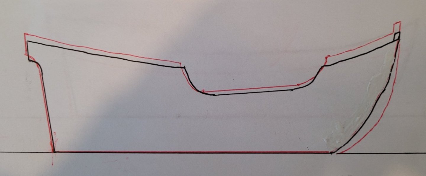
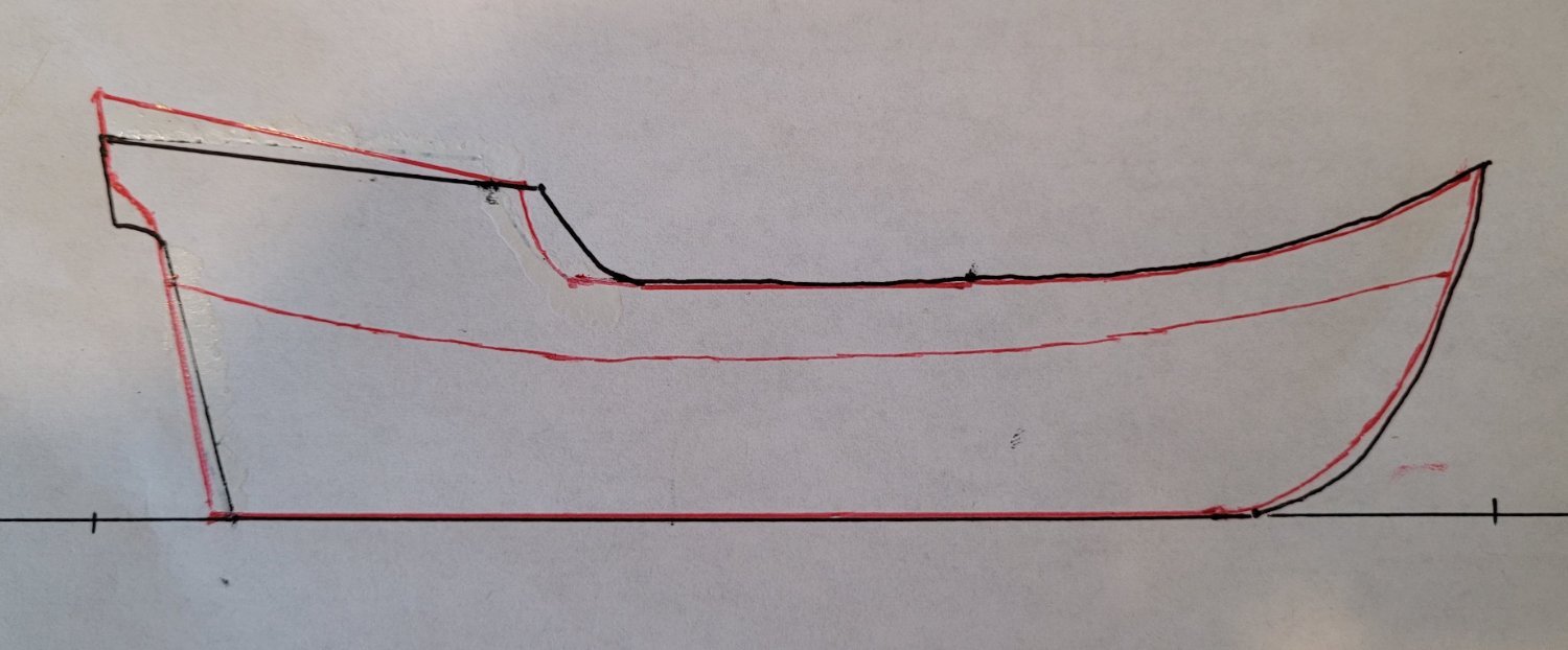
Pic 3 shows the comparison of Heller's Nina (red) to Hildago's (black). Overall, it is a close match except for the stern's upper profile for which Heller is both higher and steeper.

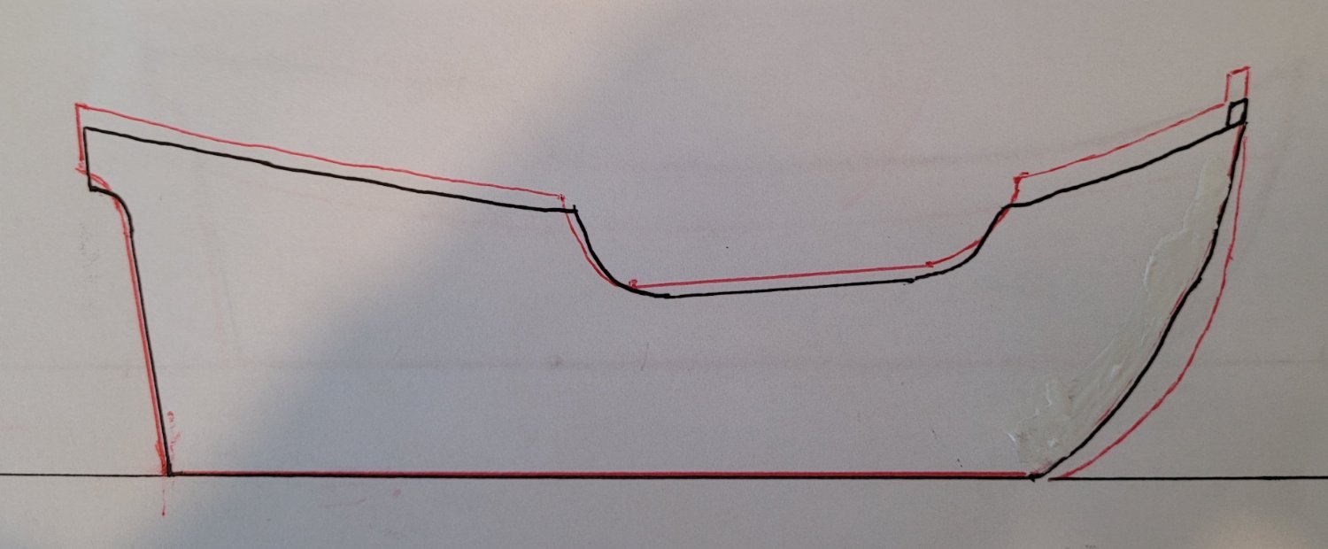
Pic 4 shows the comparison of Heller's Pinta (red) to Hildago's (black). Overall, it is a good match except for the bow's upper profile for which Heller is higher but at the same slope. Also, Heller's stem is much fuller that Hidalgo's. It must be that Pinta's stem was fuller than Nina's and that the two lower, identical Heller stems happened to match Nina's stem. If we add some comments on Santa Maria we can then discuss remidiation. In Pic 1 of post 4 the profiles of Santa Maria were compared. It is noted here that the stern upper profile of Heller's was lower and less steep than Hidalgo's.
Focusing on the stern upper profile we quantify one of the differences in Pic 5 using the slant of the stern upper profile measured in degrees. We focus on the slant because it is very discernable to the eye.
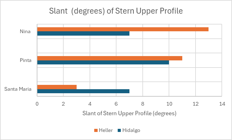
The first thing to note is that the varistion in the Hidalgo's slants (7 to 10) is much smaller than for Helller (3 to 13). Combining this with Hidalgo's statement that "much less is known about Pinta than the other ships," we could duduce that the slants for all three ships was near 8. Our target will be to decrease Heller's Nina from 13 to 8 degrees, leave his Pinta's at 10 and increase his Santa Maria's from 3 to 8.
The next thing to quantify is the verticle position of the stern upper profile. Note that these dispacements not only line up the stern upper profiles better but they also fix the slants.
The key points of interest are the aft most point on the stern upper profile and the forward most point of that profile. Heller's aft most point for Nina needs to drop 7 mm while the forward most point stays where it is. The aft most point for Pinta should be dropped 3 mm as well as the forward most point but we will leave Pinta alone since the difference is small and the slant does not need to be corrected either. The aft most point for Santa Maria needs to be raised 11 mm and the forward most point raised 7 mm.
We will not be trying to fix Pinta's forward upper profile because the slant is quite close and the displacement is modest. Nor will we try to fix Pinta's stem because it would be very difficult. In the next post, we'll show how we will neutralize the different scales of the nao (Santa Maria) 1 to 78 and the caravels (Nina and Pinta) 1 to 100. Then we will return to the modifications of the stern upper profiles.
- Papa, Old Collingwood and Archi
-
3
-
The mizzen, the main and the staysail are sown and installed (Pic 1). The outer seams of all the sails are made with 1/4" basting tape from Sailrite. A 1/16" leather punch is used to make holes in the seams for rigging lines, hoops etc. By the way, I only put ratlines on the starboard shrouds because that was done on the original - the kit is not clear on this point. I also rigged the peak halliards to be operational along with the tack so that I could demonstrate skandalizing the main (Pic 2). I had never seen this before so I thought it was an interesting oddity. Of course, when I told my son and his wife, who both sail on tall ships, about it, they said "Oddity? Hardly, it's the best way to quickly depower a gaff sail." They also said that on the boats they had been on they didn't lift the tack, but they had seen it done on a few other boats.
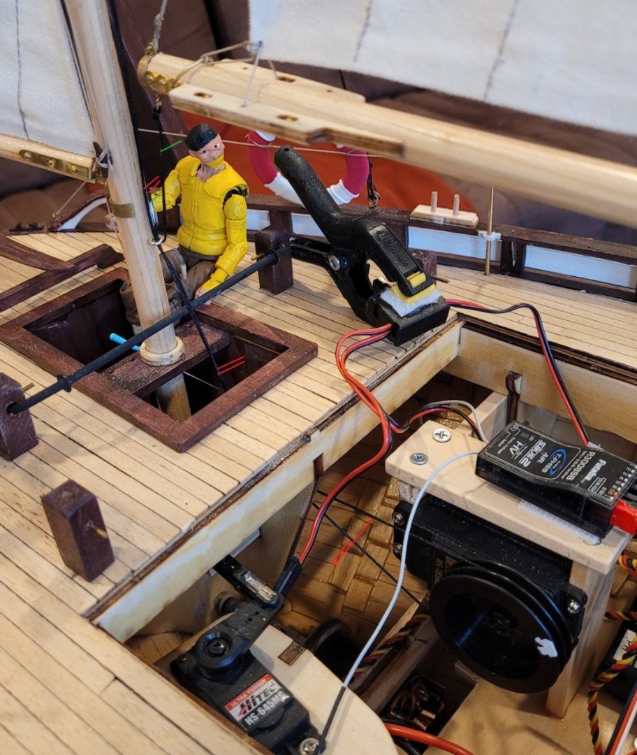
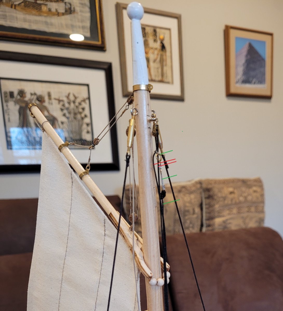
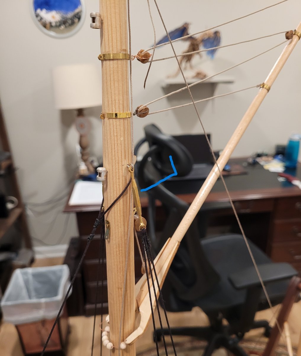
The control for the main sheet has been installed. The winch drives a loop of black cord (marked with red lines) that passes through a hole into the cockpit and then up through a screweye on the mizzenmast (Pic 3). Then it proceeds up near the top of the mizzen mast, through a small block (Pic 4). The main sheet is attached to the loop at the top (also Pic 4) (marked with green lines). It then drops through the same screweye as the loop and then goes to the end of the main boom (back to Pic 3). A few comments are in order. This is my first time creating radio control schemes so I did somethings that are maybe not customery. First, I want things to be easily visible so that I could see problems easily. Hence the thick black control cord. Also rather than hide the control loop below deck, I made it more visible by running it up the mizzen. In addition, running it up the mizzen reduces the chance that the sheet will tangle when releasing it for reaching or running. It seems to work OK but I'll still be wondering until she's on the water in the spring.

-
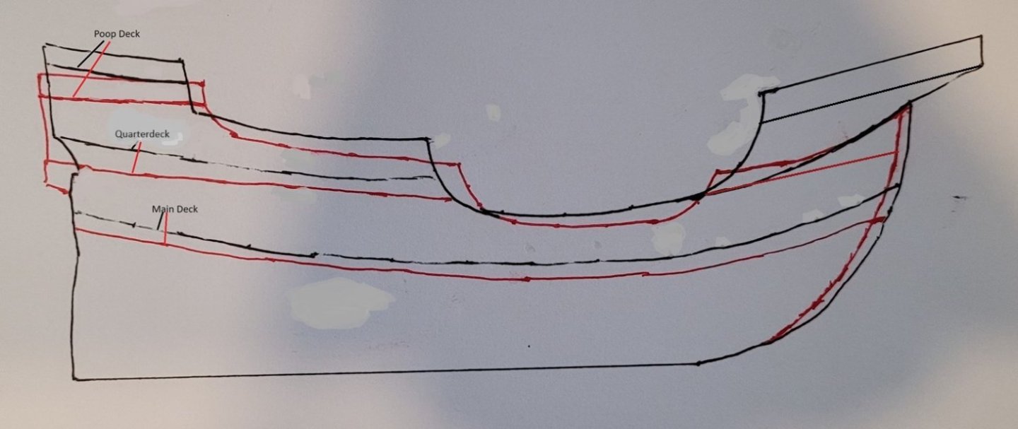
Pic 1 shows the sheer view of both Heller (red) and Hidalgo's (black) Santa Maria's hulls. In order to make the comparison, the keels were lined up and the overall lengths were made the same (Hidalgo's forecastle was not included in his overall length). There are three main differences: 1) At the stern, Heller is lower than Hidalgo by 89%. The poop deck is 89% lower, the quarterdeck is 88% lower and the main deck is 90% lower. All of these percentages are relative to the bottom of the keel. 2) At the bow, Heller does not have the castle that was common on a nao at that time, rather it has a conventional caravel type bow. 3) The cutout at the waist of Heller's hull is only 83% as wide as Hidalgo's and only 60% as deep. Possible remediation - It may be possible to raise the poop deck of the kit without upsetting the visual proportions of the stern too much. If so, we'll do that. The forecastle definitely will be added and that will not be difficult because it was normally built above a caravel type bow anyway. The kit's cutout at the waist can certainly be improved but how much it can be improved remains to be seen.
[The discussion of comparing the profiles of Nina and Pinta between Heller and Hidalgo has been removed because, I assumed, incorrectly, that the profiles of Heller's Nina and Pinta were the same since their major dimension were the same. This was discovered, when I started to assemble the hulls, to be completely incorrect. The correct compariosn between Heller and Hidalgo is described in the next post.]] -
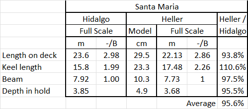
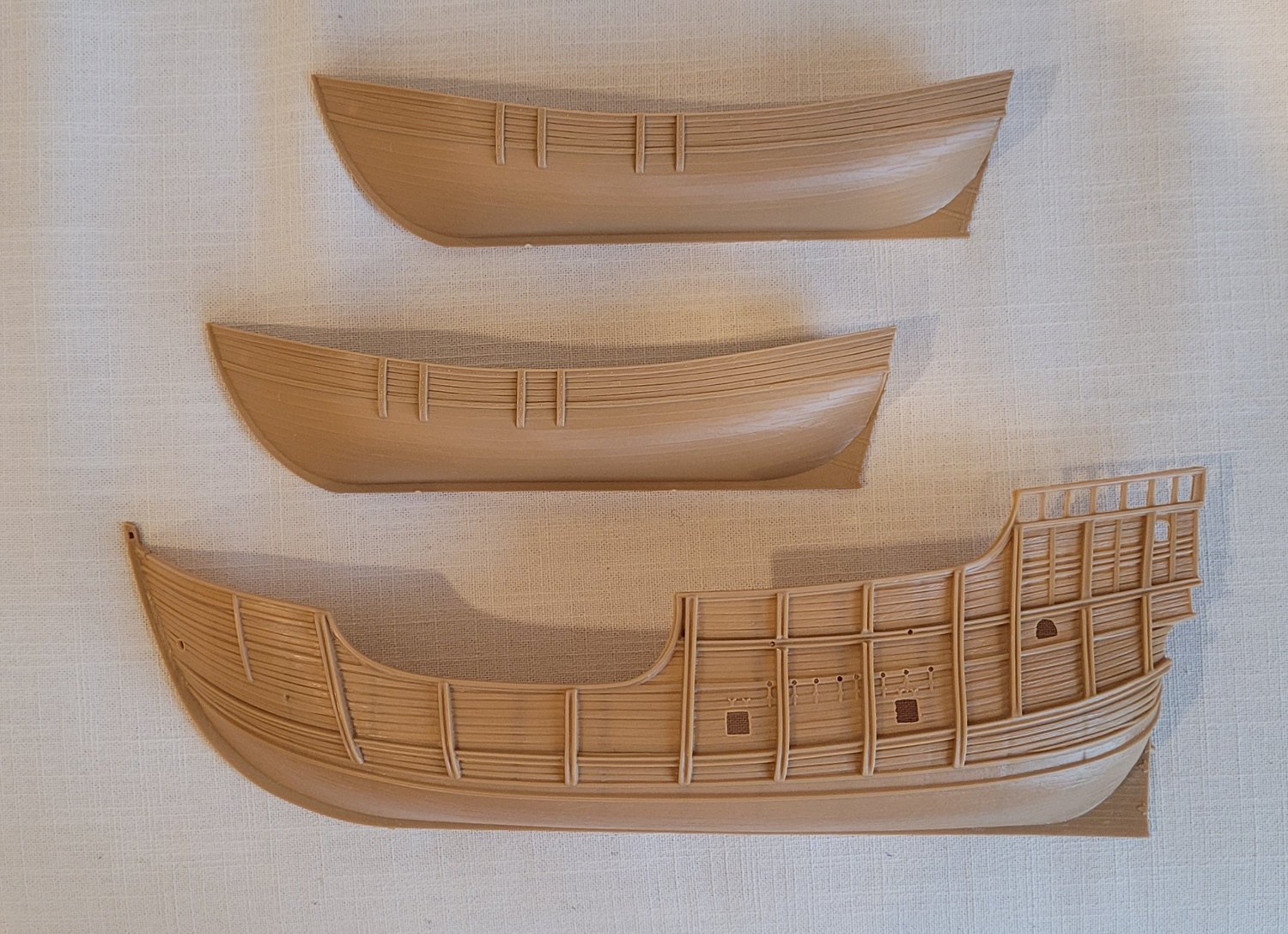
In this post, we'll compare the basic dimensions of the kit hulls with Hidalgo's hulls. Looking at Santa Maria (the table below) first we note a few things: 1) Hidalgo's hull follows the 1-2-3 formula (Beam-Keel Length-Length on Deck) used, at that time, for naos. Hidalgo strove to meet these ratios exactly in his design. 2) When we adjust Heller's hull up to full scale by mutiplying the model dimensions by 75, we find that the ratios are only approximately met. We do not know how exact these ratios were, in fact, used at the time so we cannot hold this too hard against the kit. 3) When we divide Heller's full scale figures by Hidalgo's, we find that, on average, Heller's numbers are 95.6% of Hidalgo's. We have not used the keel length in this average because it isn't clear on the kit where the keel / stem break is.
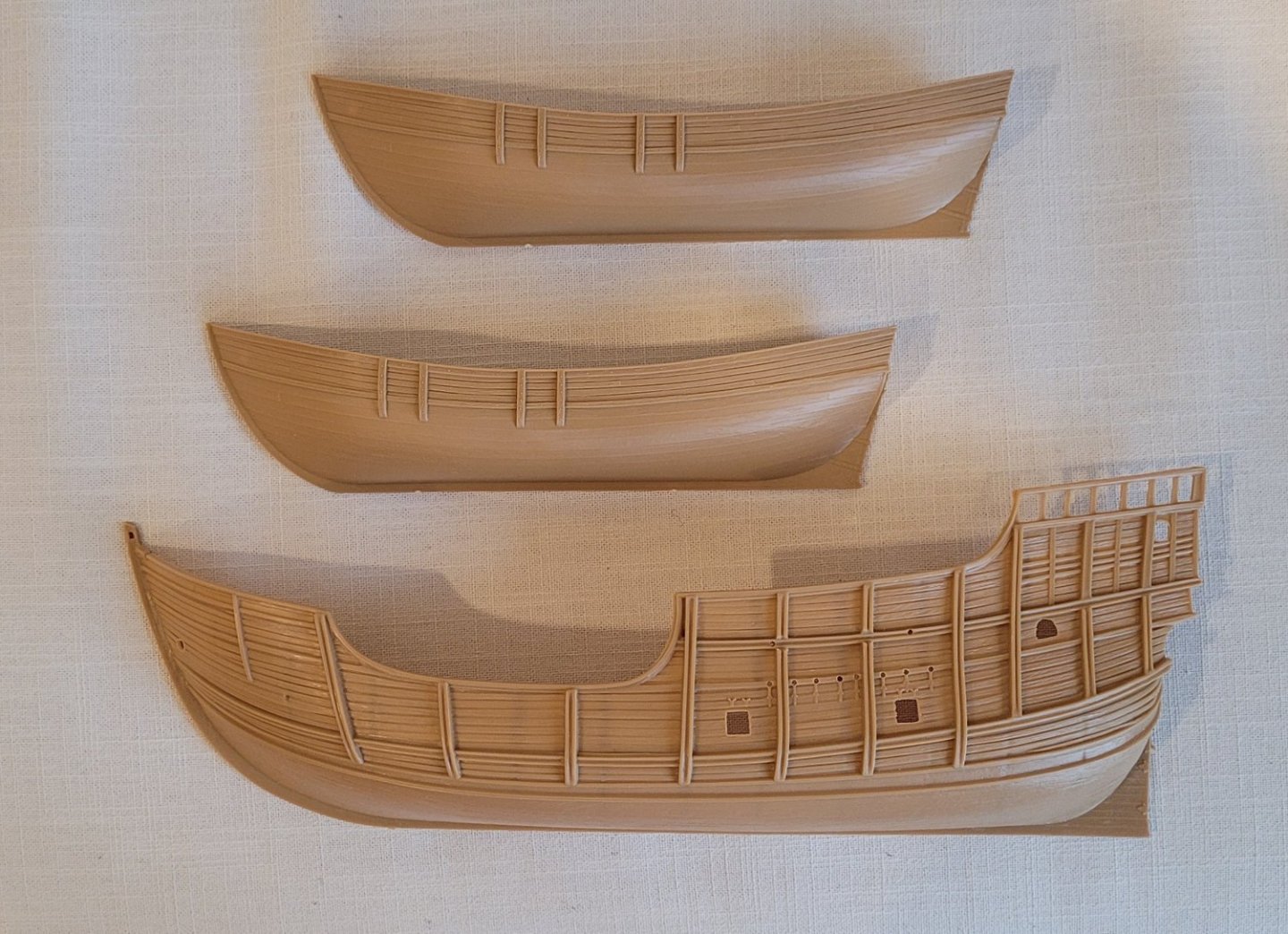
Since every post should have a photo, I've included one of the kit's hulls.
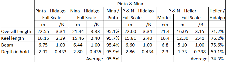
Now we compare Heller's Pinta and Nina to Hidalgo's. First, we note that the hulls of Heller's Pinta and Nina are identical. This is not an unusual assumption. Hidalgo gives slightly different values for them. On average, Nina is 95.5% of Pinta. For comparison with Heller, we average Hidalgo's Nina and Pinta and give it the name 'P & N'. Notes: 1) The ratios for caravels, at that time, were 1 - 2.40 - 3.33 - 0.435 (Beam - Keel Length - Overall Length - Depth of Hold). The normal expression was Beam / Depth of Hold = 2.30 but the inverse of that, 0.435, is more convenient for us. P&N is, on average, only 74.3% as large as Hidalgo's. This means that P & N are not in scale with Santa Maria. 3) Heller's depth in hold is only 59.1% of Hidalgo's so that the kit's P & N is not only too small overall, it is not deep enough.
With these basic differences noted, we can consider possible remediation. 1) The fact that the kit's Santa Maria is 95.6% of Hidalgo's is not at all a problem because instead of thinking of her as being at 1:75 scale, as Heller states, we just revise that to 1:78. 2) We may be able to reduce the kit's Santa Maria's keel length by 2.7 cm by a little shaping of the rabbet line and keel but even if not, except for these ratios, it is not an important measurement. 3) The fact that Heller's P & N is only 74.3% of Hidalgo's is very important as it implies the caravels are actually at a scale of 1:100, very different than Santa Maria's 1:78. A correction of sorts can be made at the display. Pinta and Nina will be at the front of a 14" shelf (7' high) and Santa Maria will be at the back of the shelf. If we use the P& N scale of 1:100 as our basis, the scale of Santa Maria will appear to increase from 1:78 to about 1:90 by being further away. In addition, by mounting her a little lower than the others, we might further induce a sense that she's yet a little smaller. 4) The biggest problem is P & N's depth of hold being 59.1% of Hidalgo's. We'll return to this deviation after considering the sheer and decks in the next posting.
-
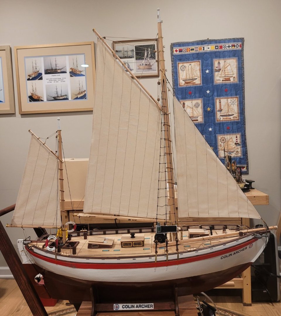
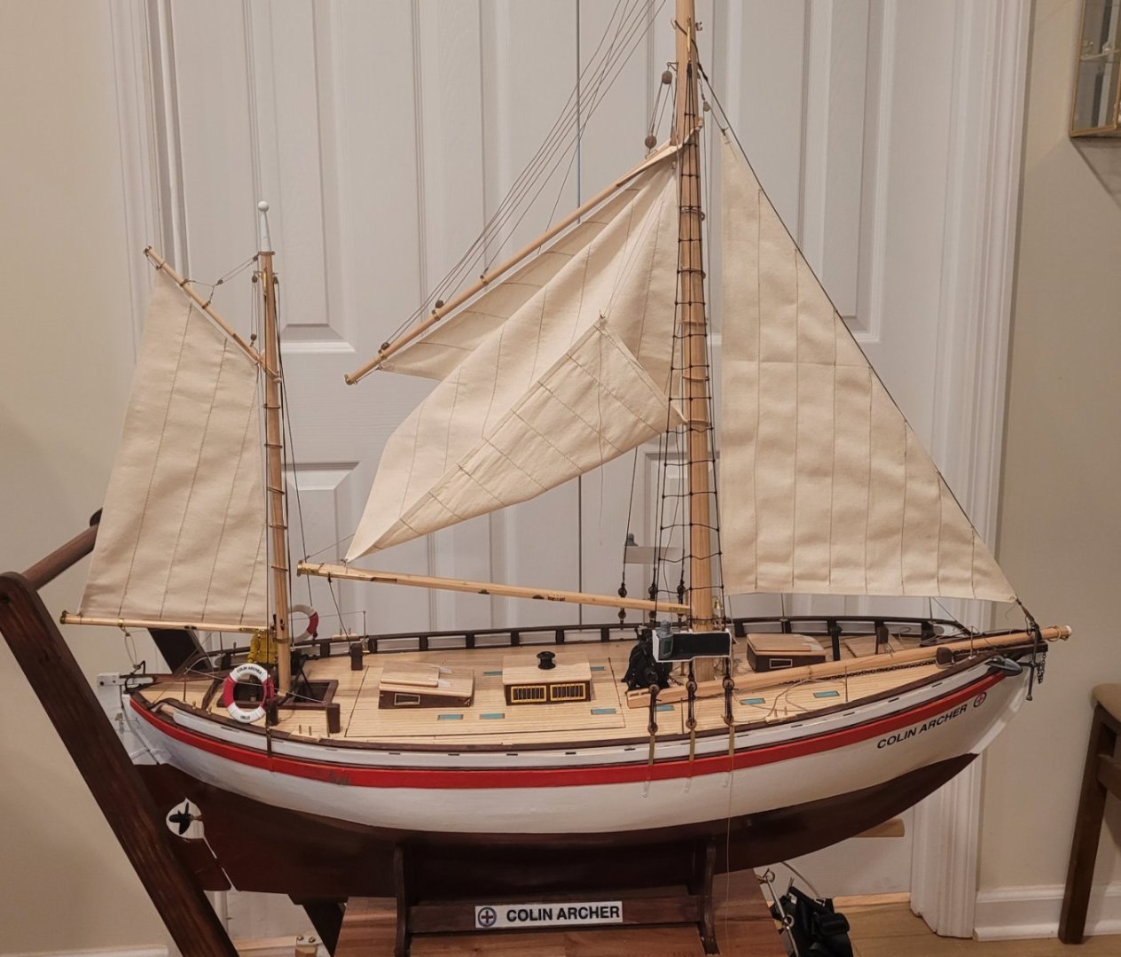
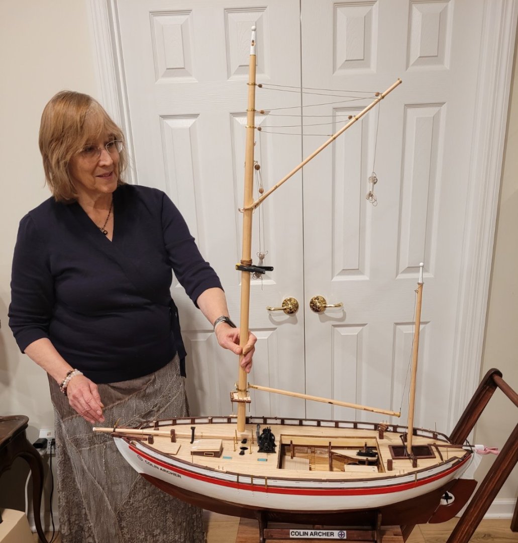
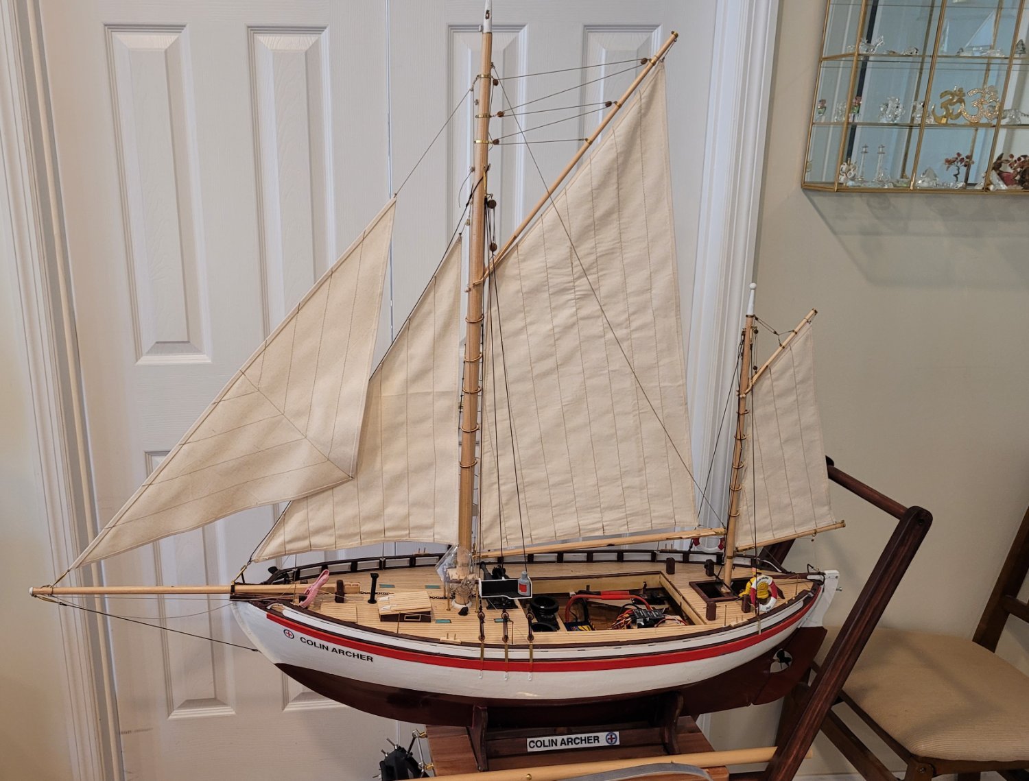
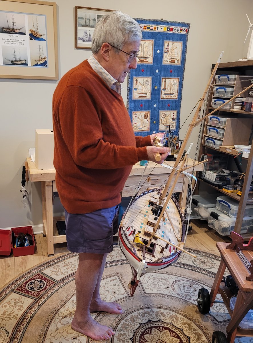
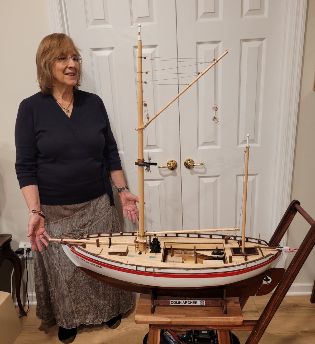
This will be the first time in more than 60 years that I will be building a model of a ship NOT built in the 1800s. It comes about because I am just finishing up a 1:15 radio-controlled model of the Norwegian designer/builder Colin Archer's prototype rescue vessel notably called 'Colin Archer' (a Billings Boat kit). In looking forward to my next project, I told my wife that I was thinking of a radio-controlled paddle wheeler. She said, "Why not do Columbus' ships and we'll put them on top of the book case - all lined up." A most interesting idea since it sort of implies long term display and I have never kept any model for more than 2 or 3 years. So I thought about it and decided that it was a great idea with two conditions. 1-- I would use a plastic kit as a starting point because I do not want to commit a huge amount of time to this project and 2-- I would use the 1966 book Columbus' Ships by Jose Maria Martinez-Hidalgo and edited by Howard I. Chapelle as my exclusive source. My intention is to modify the kit to match Hidalgo's informtion where-ever practical and use the kit's intrinsic information everywhere else. The second posting will describe how well the three hulls in Heller's kit match the hulls described by Hidalgo.
-
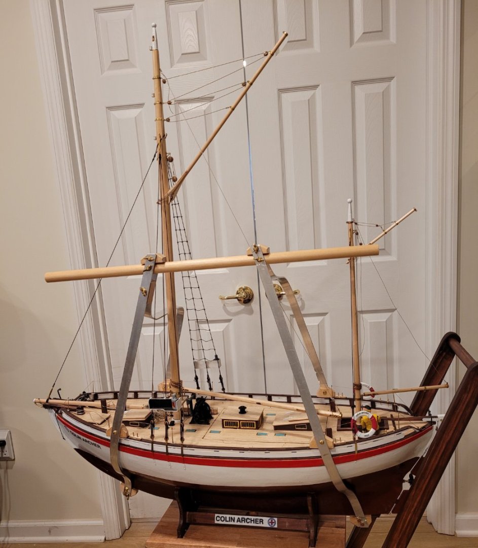
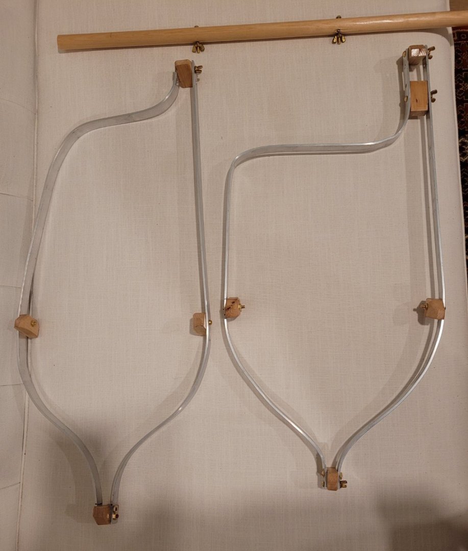
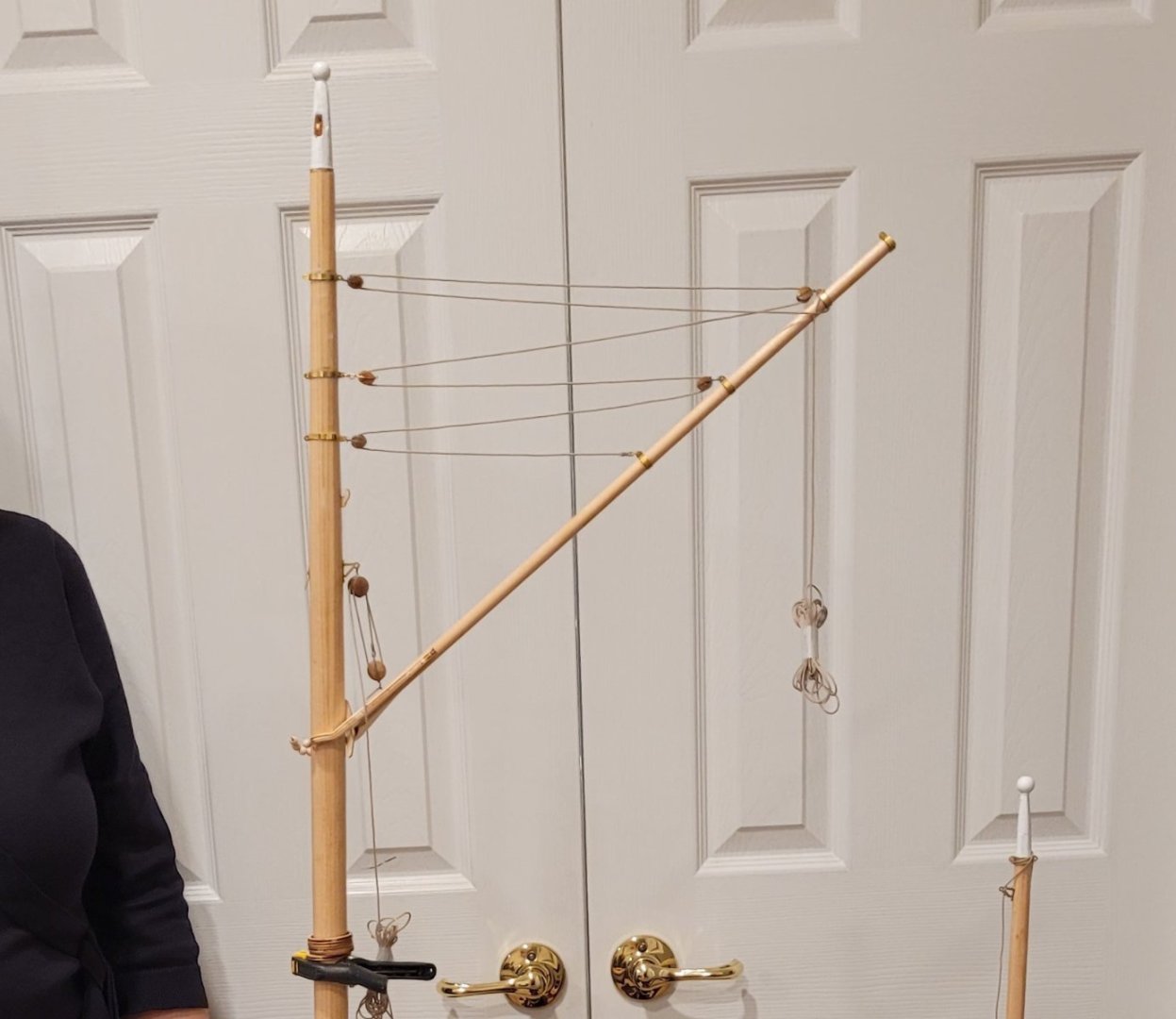
Now for the cradle. Pic 1 shows the completed cradle in position. If you compare the handle (wooden dowel) with the door panels, you'll see that it is level! Both supports are made of 1/8" x 3/4" aluminum. The handle is skewed to port to avoid the sails. Each support has a wooden shoe at the bottom which supports the boat's weight. Moving up, 2 more shoes are seen on each support which rest on the bulwark rail. At the top, another shoe on each support accepts the force of the handle holding up the ship. The forward support has an additional spacer just below the handle. 5 wingnuts need to be removed to remove the cradle and, of course, screwed on to install the cradle. It takes about 4 minutes to put the cradle on and 3 minutes to take it off.
Pic 2 shows the disassembled cradle.
Since the handle is skewed to port, the model does not hang vertically. Pic 3 shows that this causes no problem since the deviation from verticle is modest.
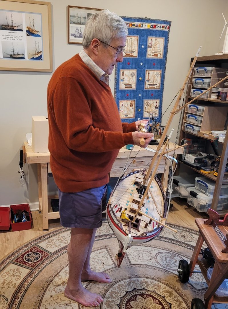
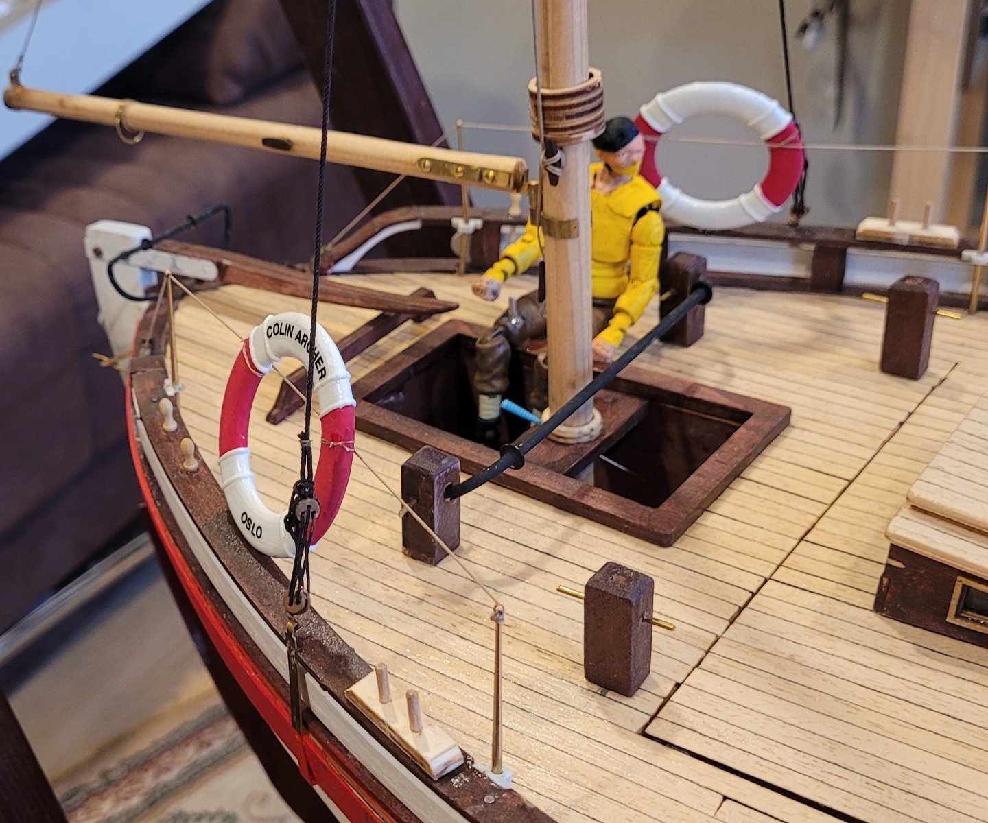
Pic 4 shows some recently added details: The helmsman, the life line around the deck and the life preservers. The helmsman was a 1:15 superhero [not one that I was familiar with] that was cut, scrapped, sanded and painted. The midship stanchions on each side are ommited along with the midship life line to avoid accidents when removing and replacing the RC cover. The life preservers are lashed to the life line. The blue hilted sword keeps the mizzen mast from rotating. I'd like to say that ever since I was 12 years old (64 years ago), when I built my first wooden ship model (Model Shipways' Young America), I have left a blue hilted sword some place in each model as a sort of signature. Unfortunately, this is the first time I've done it but I will continue to do it (if I remember) with future models.

Pretty much the only thing left is the sails and setting up the three sail winches. Once I select a sail cloth, I will be all set! If anyone has any suggestions for sail cloth that will look a little authentic, I'd love to hear. BB has supplied a little bit of something nice but not near enuff for a full set of sails.
-
The seatrial in the pool verified that the fix to the propeller flow was totally successful. I backed down the End Points for both forward and reverse to 50% to avoid superfast speeds. The link to a video of the action under power is: https://drive.google.com/file/d/1lnhsdz5a7odBhvLbz6PQ6rRbjOPRZJ4l/view?usp=sharing. The seatrial was further successful in surfacing two problem areas.
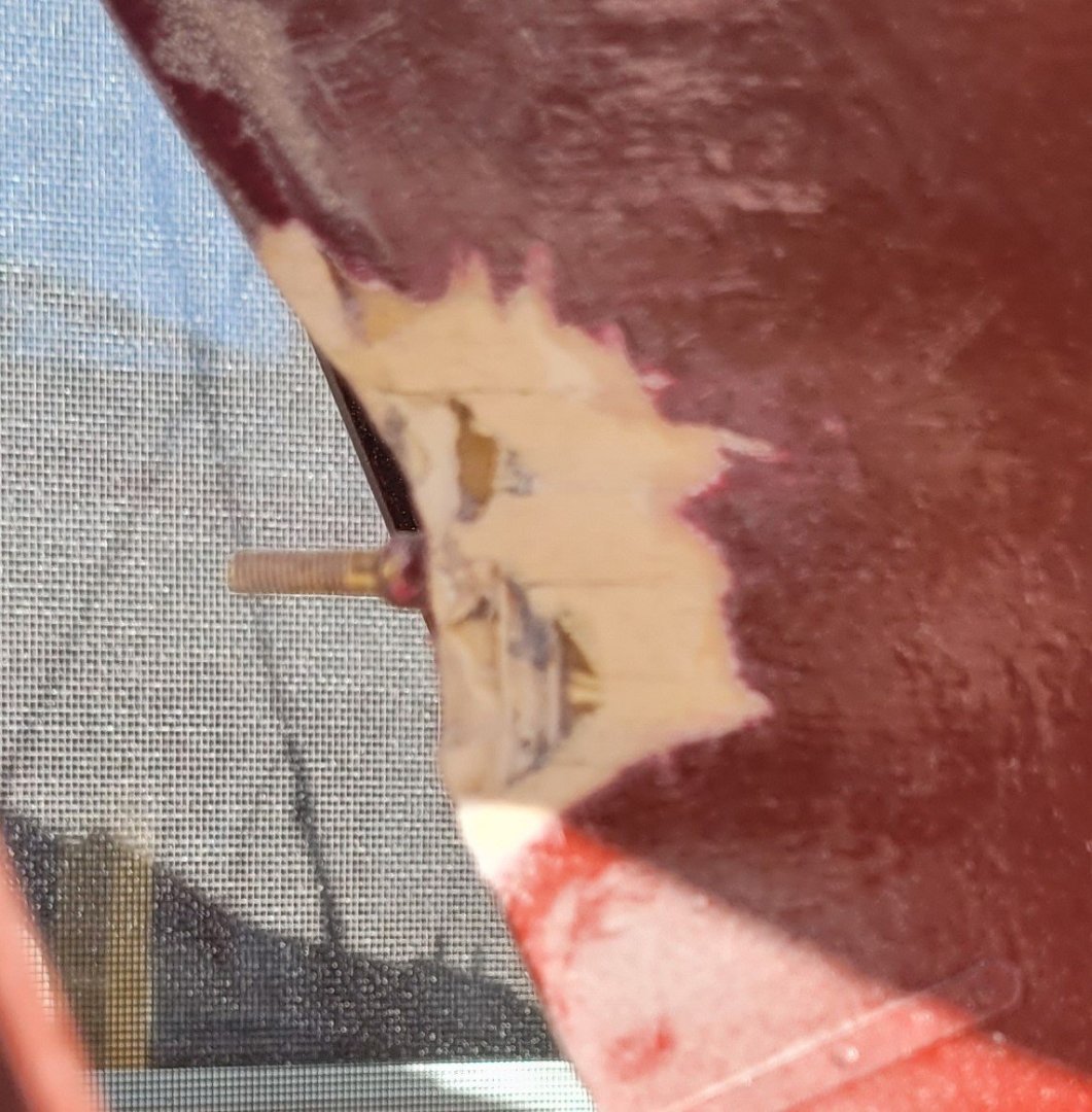
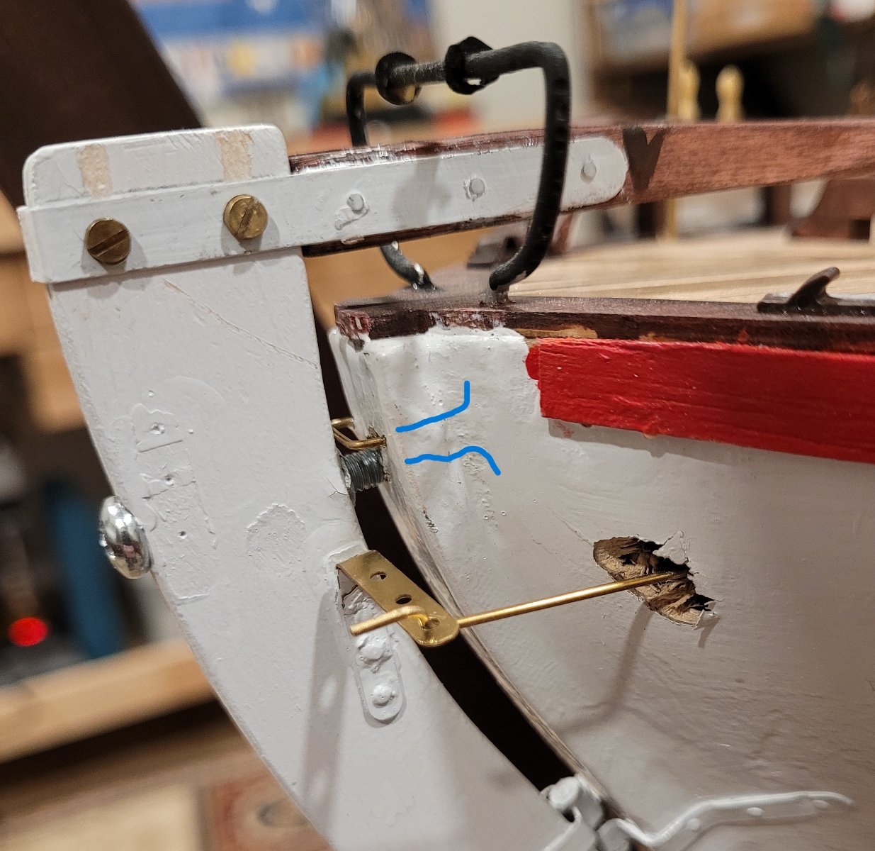
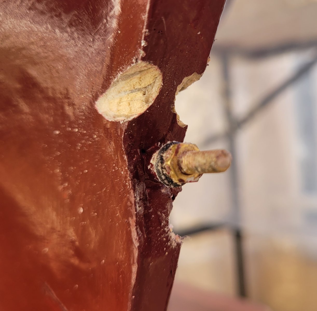
Problem 1-- The rudder moving upwards and disengaging the pintles and gudgeons. Pic 1 shows the fix. A little sort of 'traveler' was attached to the stern post (indicated by upper blue marker). Then a machine screw (indicated by lower blue marker) was passed through the upper part of the rudder and screwed into a nut inset in the forward edge of the rudder so that the end of the screw passed just under the 'traveler' thus preventing the rudder from rising up. The machine screw is unscrewed to clear the 'traveler' to remove the rudder.

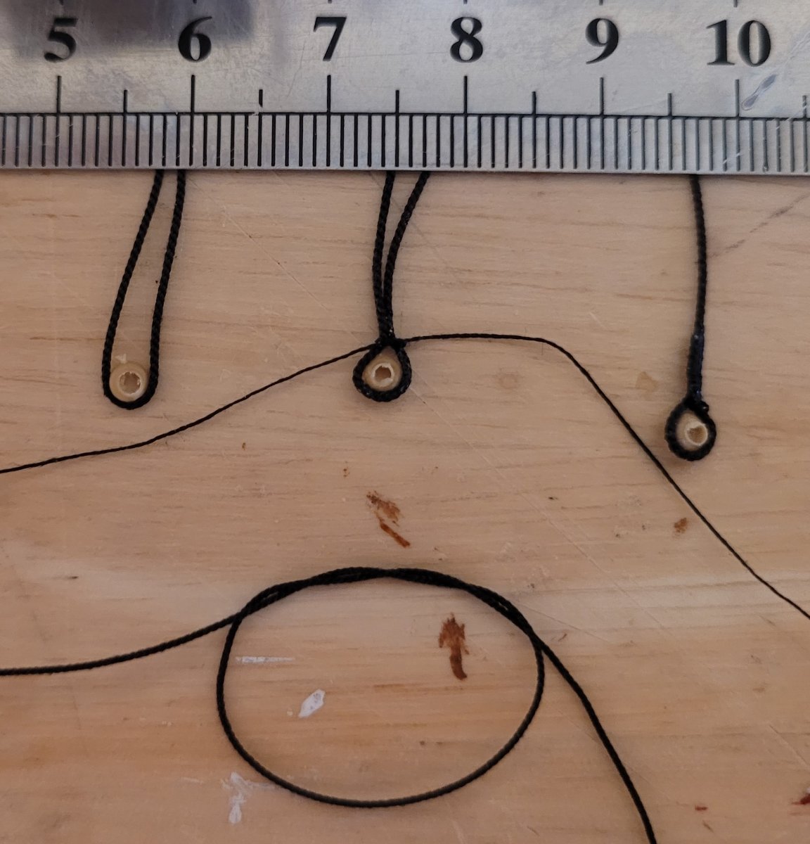
Problem 2-- One of the turnbuckles unscrewed while rolling the boat 300 yds to the indoor pool. This was solved by using nail polish - In Pic 2 The use of turnbuckles (indicated with blue marker) for the shrouds is seen to enable the mast to be lifted out of the hull for transport.

Finishing off the deadeyes and lanyards follows - not a fix just some finishing touches. The pictures of the Colin Archer that I had access to, did not show clearly what happened to the ends of the lanyards after reeving the deadeyes so I followed Jeppe's practice on RS14 Stavanger. He takes the end of the lanyard off the lower deadeye and puts a lanyard hitch around the shroud above the upper deadeye (indicated by the upper blue marker). [I used a clove hitch.] Then he takes several half hitches around a segment of the lanyard just below the upper deadeye (indicated by the lower blue marker). The running lights, tied to the shrouds, are also installed.

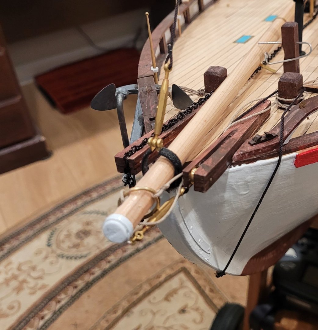
The last Pic, 4, shows some details at the bow and on the end of the retracted bowsprit.
1-- The stowed anchor is shown tucked under the bulwark rail because it was the only way I could see to gracefully place it. Based on photos of the actual vessel I think the rail may extend too far forward making it hard to fit the anchor forward of the rail where it belongs. Lashings to the starboard post are seen.
2-- The turnbuckle for the mainstay is clearly seen. Nail polish, of course, used here. There is no actual fitting here but, as with the shrouds, the turnbuckle facilitates removing the mast.
3-- The black bobstay is raised out of the water when the bowsprit is retracted and pulled onto the deck. It is shown here looped behind the port post.
4-- The tan line (jib outhaul) is used to pull the jib ring (with the jib tack attached to it) out to the end of the bowsprit after the bowsprit is extended. I've looped the outhaul with the 'inhaul' (my name for the line that pulls the ring in) for less clutter to form a contiuous loop that is wrappered around the port post.
The next post will address an important engineering issue which is getting the boat into and out of the water - at 25 lbs or so, I can't do it myself.
-
Sundt,
Thanks for the videos. You may also know about the official website for the Colin Archer at https://www.colinarcher.no/ which has more photos and videos.
Doug
-
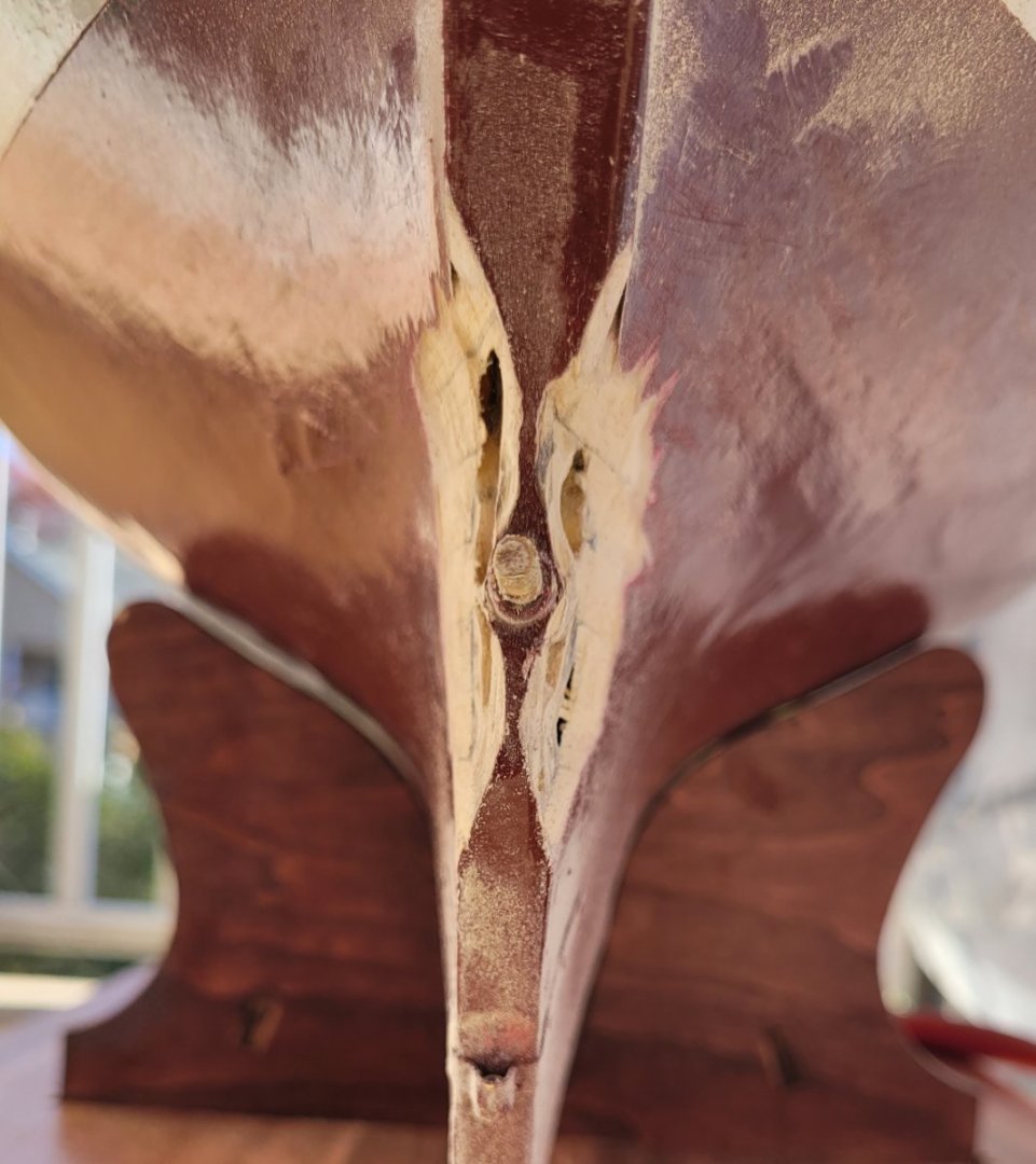
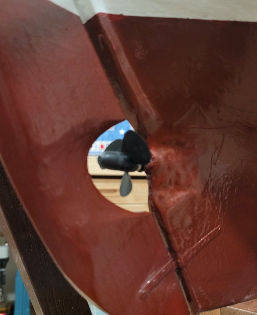
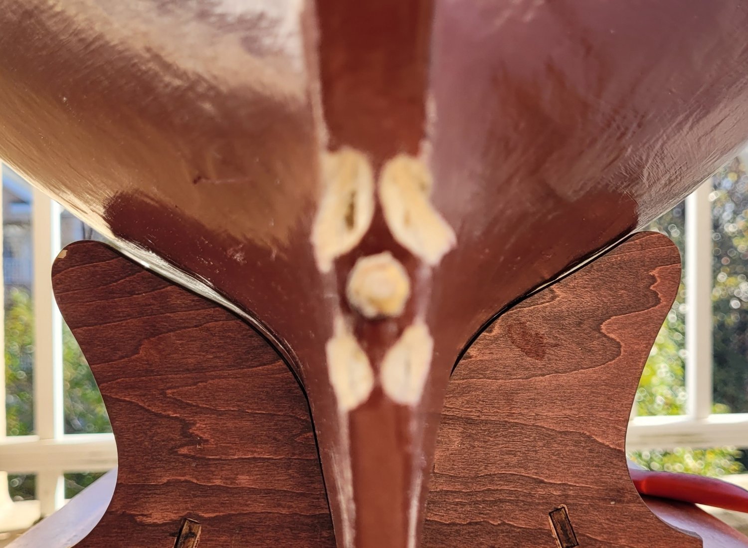
At this point I put Colin Archer on her first sea trial in the tub to see how well the motor worked. It turned out to be sort of pathetic. I estimate a top speed at something like 6 inches per minute (0.006 mph). Hardly enuff to deal with difficult situations on a pond. After a few consultations, I took a good look at the hull around the propeller and noticed that the stern post was quite wide (3/8" to 1/2") in the vacinity of the properlor. Thus the propellor (only 1 3/8" in diameter) was largely churning dead water. I decided to trim the rear edge of the stern post down to about 1/16". Pic 1 shows the situation before trimming with two small gouges at the start of trimming. Pic 2 shows the thinning in progress with the propeller shaft boss emerging.


Pic 3 and 4 showing the final thinned result. Having broken through the fiberglass and some planking, some spaces adjacent to a bulkhead are visible. A layer of fiberglass and two additional layers of resin will be followed by 3 coats of paint. The rudder is also being thinned by removing about 1/3 of it's thickness, so it is about 3/16" in the vicinity of the propeller with tapers to 1/16" at the leading and trailing edges instead of the overall 5/16"thickness.
Pic 5 shows the completed repair. The quality of the painting is marginal BUT she flies like a jet airplane. I can't make a speed estimate yet because going forward with just a touch on the throttle she tried to climb out of the tub. When she's in reverse she's more stately. Her next sea trial will be in a pool and I'll probably turn the End Point setting down to avoid planing! To say that this repair exceeded my expectations would be a total understatement. One unexpected development - at some point the propeller unscrewed itself. I solved this problem with Strong Locktite.
This was quite stupid because 250 degrees will be necessary ro remove the propeller which is plastic! In the next post I learn to use nail polish.
-
So, last post I said I would focus on the controls for the 2 fore sails next. That is not true. The reason is that I want to get started on the actual control scheme for the sheet of the mainsail. To do that, I need, at the minimum, the main boom in operation. That suggests that the fittings on the main mast need to be finished so that's what I'm going to focus on for this post in addition to the technique I'm using to be able to take the mainmast out of the hull for transportation.
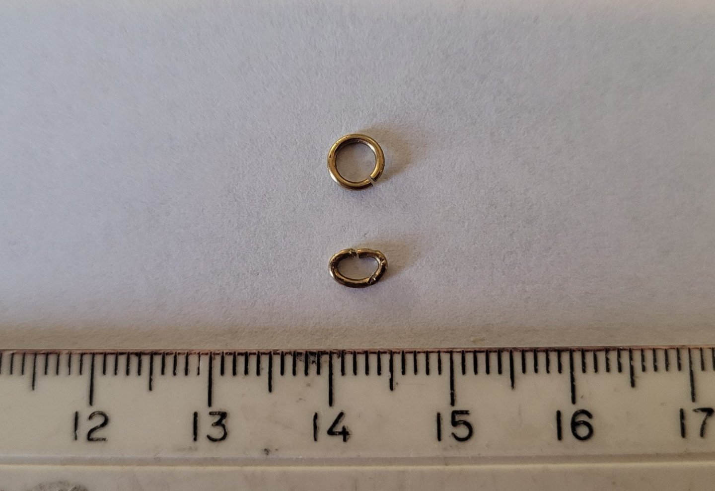
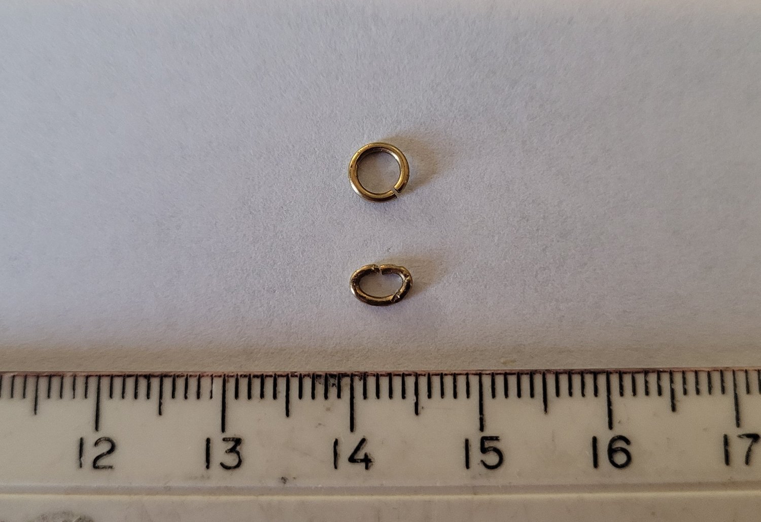
Pic 1 shows the rigging for the main gaff. Billings provides cute little plastic shells for the blocks and beautiful brass sheaves. The only problem is that the width of the slot in the shell is less than the thickness of the sheave so there is no way the sheave can rotate. The good news is that the line slides easily even without rotation so no problem. All of the bands are made of thin brass sheet so whenever lines will be attached I worried about abrasion cutting the line. So I introduced something like a shackle (in function) and a link of chain (in appearance) to avoid the problem. BB provides a whole lot of brass rings (I think for the topsail). I cut out about 3 mm and squished the rest into the chain link shape, Pic 2. If the strop of a block is line, I use one of these things. If the strop is steel wire, I don't.
On the right of Pic 3, the spider band can be seen which also provides the pivots for the post on the end of the boom - together the pivots and post constitute the gooseneck. At the far left of Pic 3 a turnbuckle (from Harbor Models) can be seen attached to the stem fitting that constrains the retractable bowsprit. This will be discussed shortly when we talk about removing the mainmast from the hull.
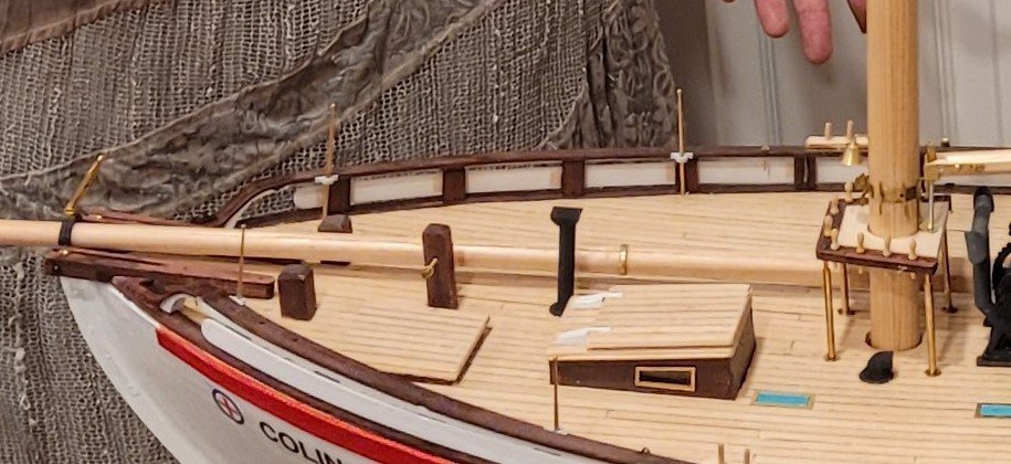
Now we discuss removing the mast for easy transportation purposes. Pic 4 shows the mast in place. Pic 5 shows the mast lifted out of the hull. The unusual thing about this is that the fife-rail is attached to the mast and stays with it when the mast is lifted up. The reason this happens is that both the standing rigging and the running rigging are involved in allowing the mast to be lifted out. The standing rigging, i.e. the forestay and the 6 shrouds, are obvious impediments and they are dealt with using 3 turnbuckles - one for the fore stay and 1 each for the port and starboard triple shrouds. Using the turnbuckles, allows these lines to be released freeing the mast to be lifted out. This wouldn't work very well with the running rigging - there is too much of it and it doesn't correspond to anything real. But, on this ship all the relevant running rigging, i.e.. peak and throat halyards, fore sail halyards, topsail lines (halyard, sheet and tack) and the flag halyard, lead to the fife-rail. So everything is taken care of by attaching the fife-rail to the mast. This is done with a little 'platform' that is left white so that the real fife-rail is left visible.
One thing that I'm a little proud of is how the 4 posts of the fife-rail are handled. All four are cut, of course, but not at the same height. Each cut is 3mm higher than the preceding cut. Brass tubes of equal length are slid over the lower parts of the posts. Then, when the mast is lowered into the hull, the longest upper portion is fed into its tube. When it is securely in place the second longest upper portion is fed into its tube and so on until all 4 are in their tubes and the whole thing slides down. If the 4 cuts were all at the same height it would be hard to line them all up simultaneously.

-
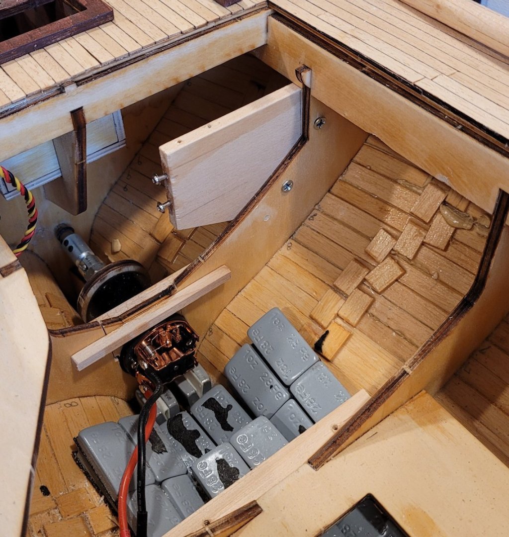
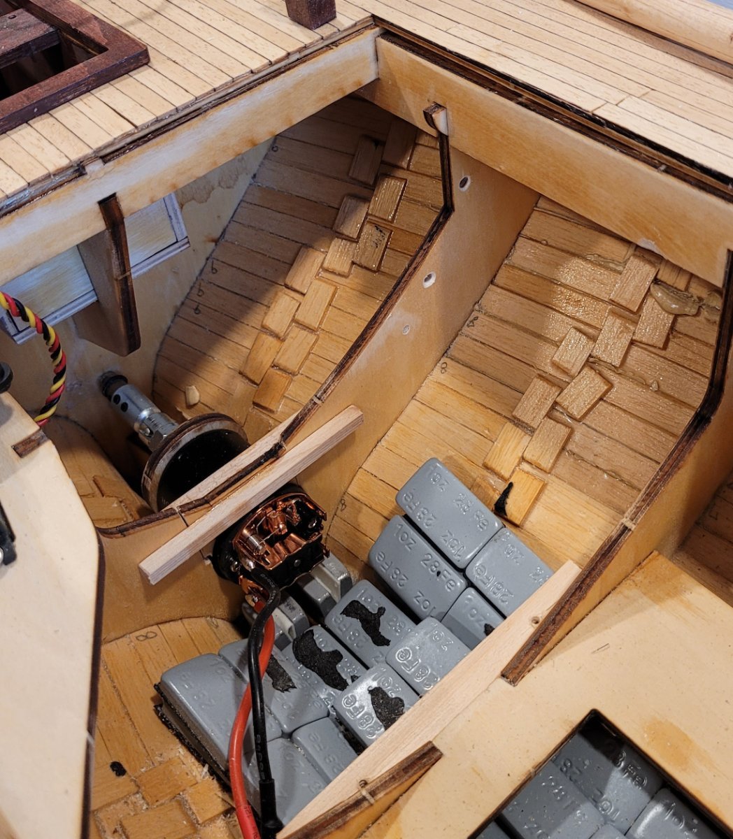
Now for the winch servo that will control the main sheet. This post comes just a few hours after the last post because the motor had to be in place before this work could be installed. The work itself was actually completed a few weeks ago. Pic 1 takes up after the motor was installed but two new holes can be seen in the bulkhead.
Before going into the details, I want to comment on the first two controls. BB is very clear that they provide no support for RC installations, however, if you consider the rudder control, you'll notice that they provide a piece of wood on which the servo fits and that piece of wood notches beautiful into two bulkheads. I myself was very appreciative!
Then we move to the second control, the motor, and BB is still helpful. There is a piece of wood that screws onto the motor and slips into a notch on the keel. Along with a hole cut in a bulkhead, the motor is correctly aligned with the propeller shaft which is great. Even though I had to move the notch and open up the hole in the bulkhead, BB provided a lot of assistance for this installation.
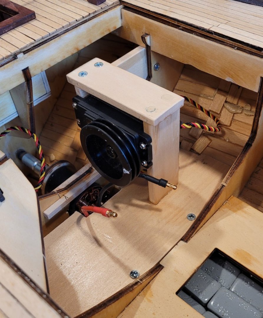
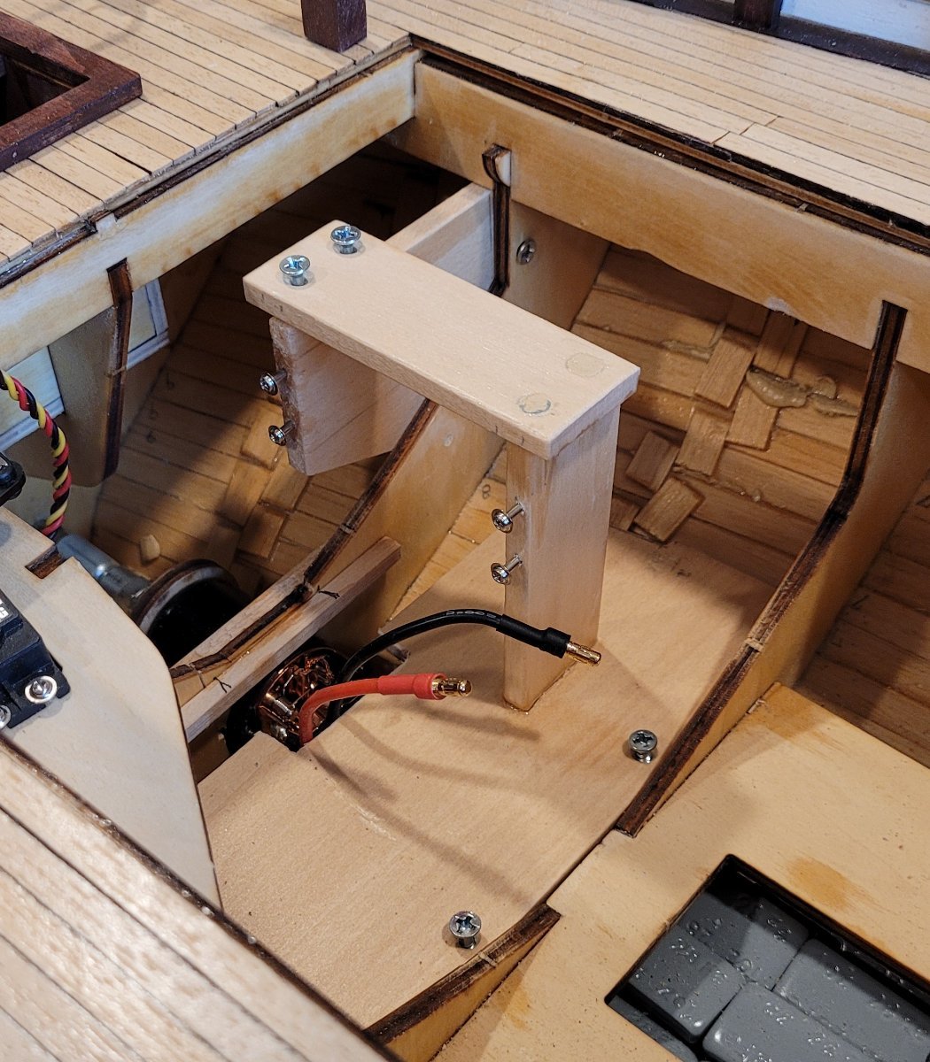
Then we come to the third control, the main sheet winch servo, and the only help that BB provides is a diagram of where it needs to be. I'm not complaining because this is how I learned that the winch drum should rotate around an horizontal axis and that the drum should be roughly on the centerline of the boat so that the main sheet will smoothly pass up through the cockpit to the end of the main boom. I am only pointing this out because of the need to create a structure for the winch servo based on my own experience and creativity was very challenging since I have no RC experience! The structure that I have designed can undoubtedly by much improved on, I just hope it works. One thing I am very glad of is that I realized that I have to be able to disassemble it if the need arises. Pic 2 shows what I am calling a bulkhead doubler because I can't think of another name. Obviously the two holes were for screws to hold the doubler!

Pic 3 shows a more complicated addition that has 3 pieces of wood: The lowest piece provides a foundation for the other pieces to which the winch servo for the main sheet will be attached. Note that the little horizontal piece on top, screws into the bulkhead doubler. That makes it really strong. In addition, the lower piece of wood will later provide a foundation for some of the other RC components (e.g. the ESC). In Pic 4 the actual servo is installed. The pictures are a little misleading because it might seem that with the wood structure in place, I just slide the servo in to its place. Unfortunately, it's not so easy. I have to loosen all the screws of the support structure so that it becomes wobbly in order to get the servo into its place and then retighten all the screws.

The actual connection to the sail will have to wait until there is at least a main boom but I would like to present my plan for comment. Only a single line will exit the winch. It will pass up through the cockpit and then attach to the end of the main boom. The control in neutral position will have all the line on the winch drum and the sail be in line with the center line of the boat. A little bit of line will be unwound for close haul, more for reaching and pretty much all of it for running. When running, the tip of the boom will be about 17" from its position when the boom is on the centerline. The servo will be able to release about 15" of line with 3.5 revolutions of the drum - 17 & 15 are close enough for engineering work (I think). Of course, a possible problem is that if the wind does not cause the sail to keep the line reasonably taut as it is released from the winch, it could get tangled - not good. One possible fix for this is to run the line up the mizzen mast through a block, to a weight, then down to a fairlead at the level of the boom and then to the boom end. This would allow the line coming off the winch to be relatively taut and extra line could lie in a bight in free space where it would be unlikely to tangle or catch on anything. Any comments would be welcome.
Later we will see that the 2 controls operating on the staysail and jib sheets will not have this problem because these sails both have two sheets and when the winch releases one sheet , it will take up the other at roughly the same speed therefore the whole loop will remain more or less taut enough to avoid tangle. A real advantage to this arrangement is that the foresails can be back winded if needed. Next post will be the controls of the foresails and again BB has some helpful diagrams but the implementation is left up to the modeler.


 x
x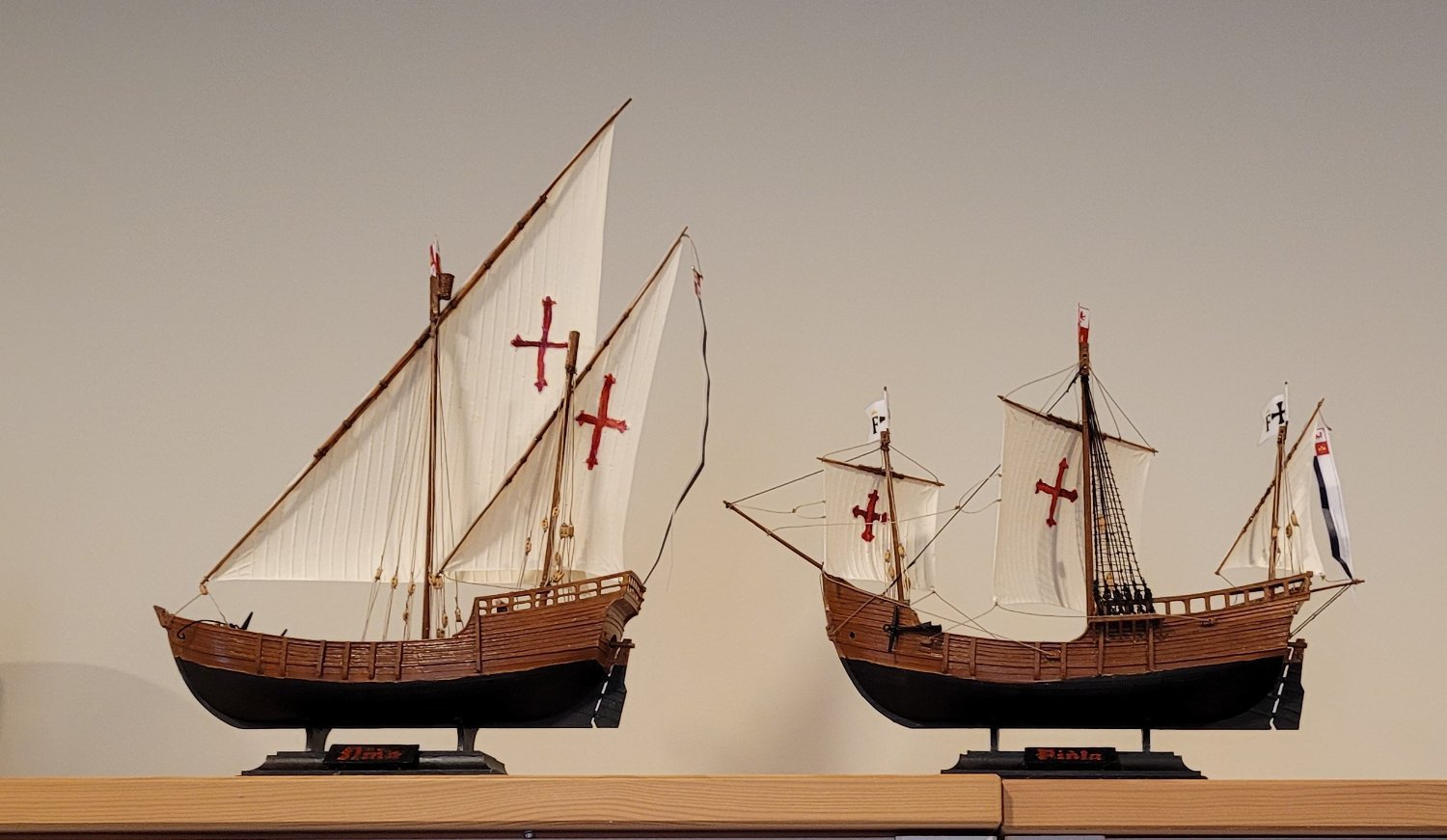


RS1 Colin Archer by Doug McKenzie - Billing Boats - 1:15 - RADIO
in - Kit build logs for subjects built from 1851 - 1900
Posted
Translation from German
"Hello Mr. McKenzie, I would like to thank you very much for your construction report, which will help me a lot when building my Colin Archer."
You are most welcome, Andreas. I wish you good fortune with your build.
Doug