HOLIDAY DONATION DRIVE - SUPPORT MSW - DO YOUR PART TO KEEP THIS GREAT FORUM GOING! (Only 13 donations so far - C'mon guys!)
×


hamilton
-
Posts
1,931 -
Joined
-
Last visited
Content Type
Profiles
Forums
Gallery
Events
Everything posted by hamilton
-
 Thanks for trying Ronald! And thanks for dropping in Nearshore! It looks a little rough compared to others, but I'm very happy with the results so far. hamilton
 -
It didn't!!
-
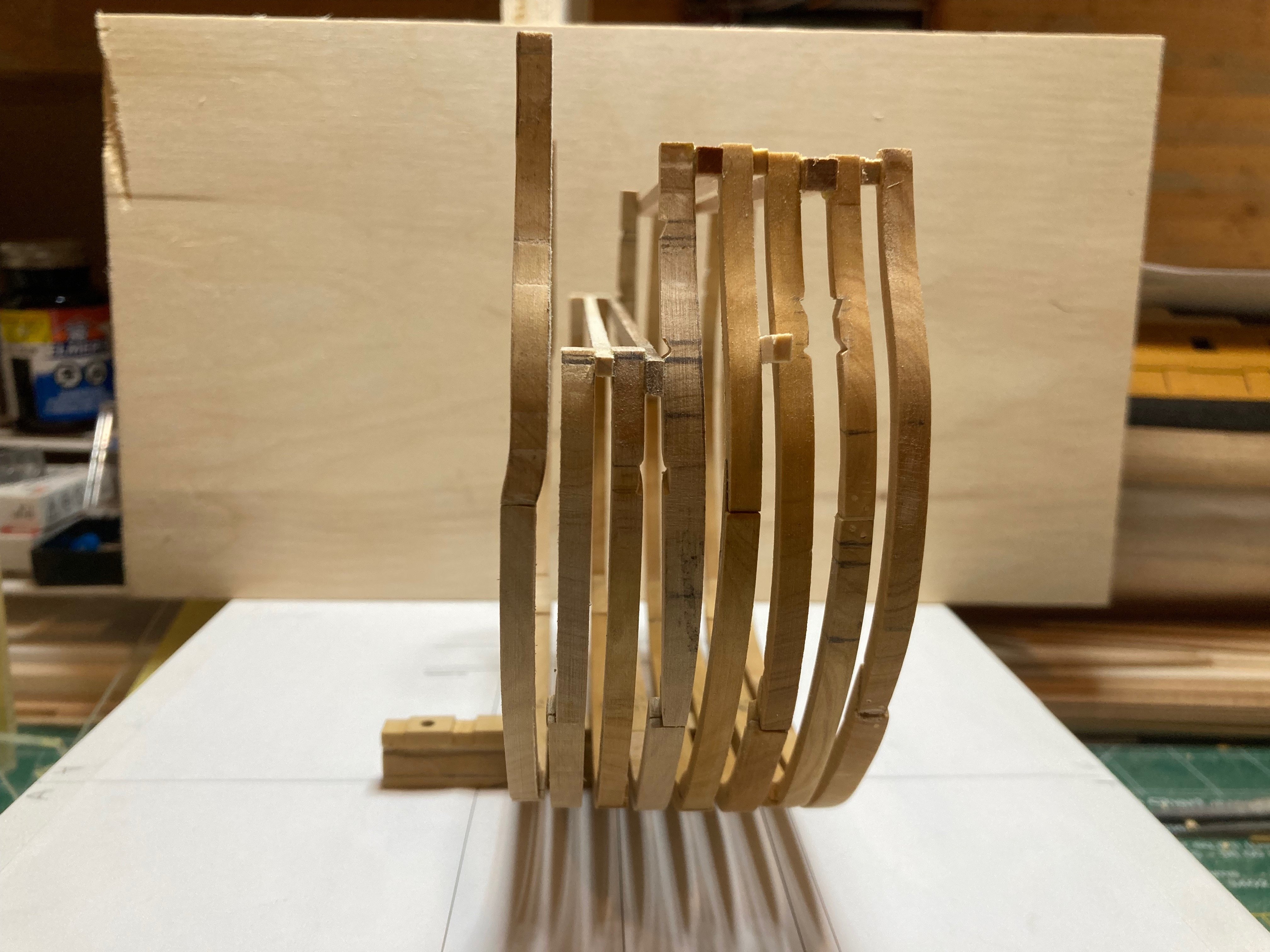
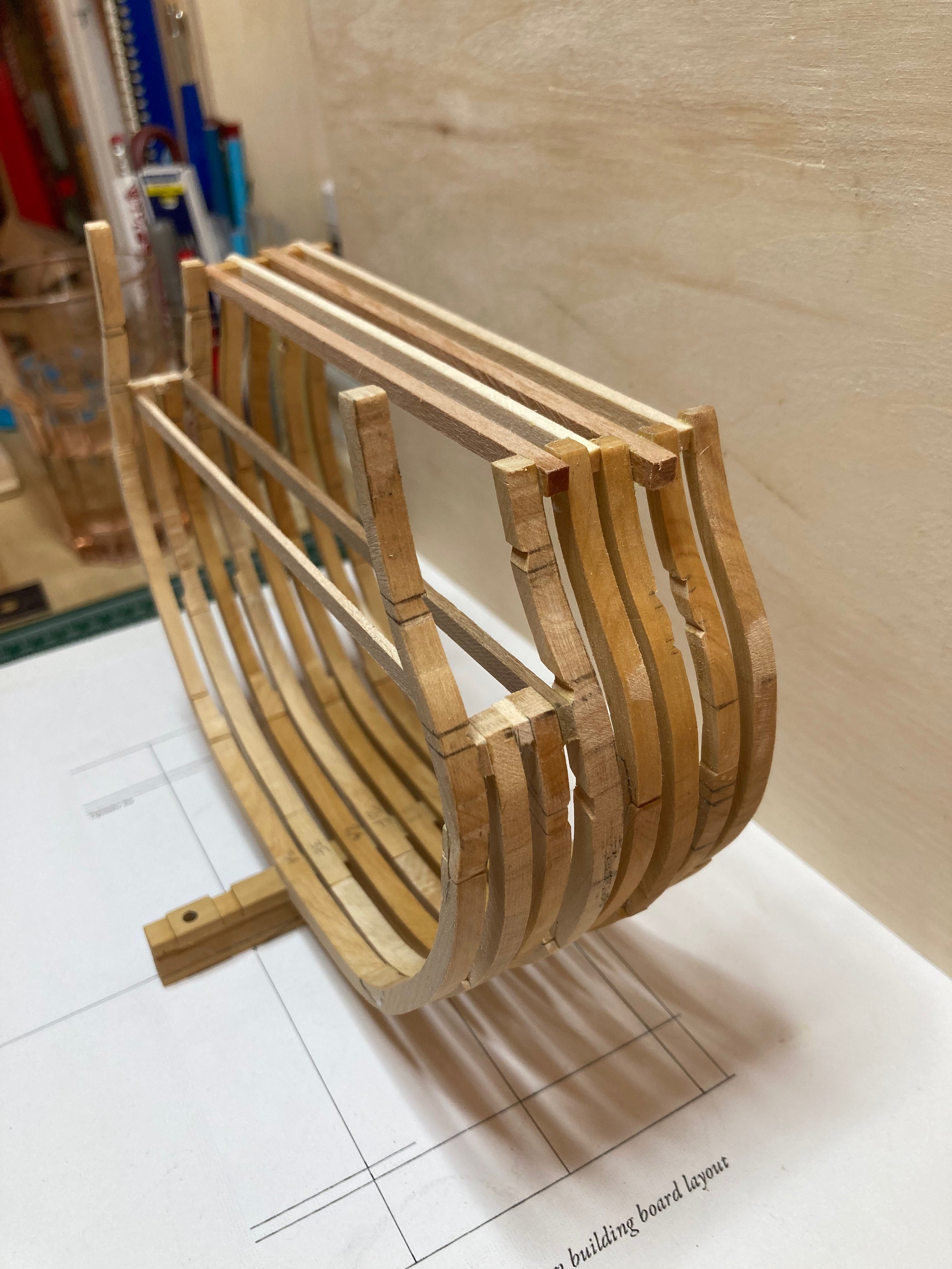
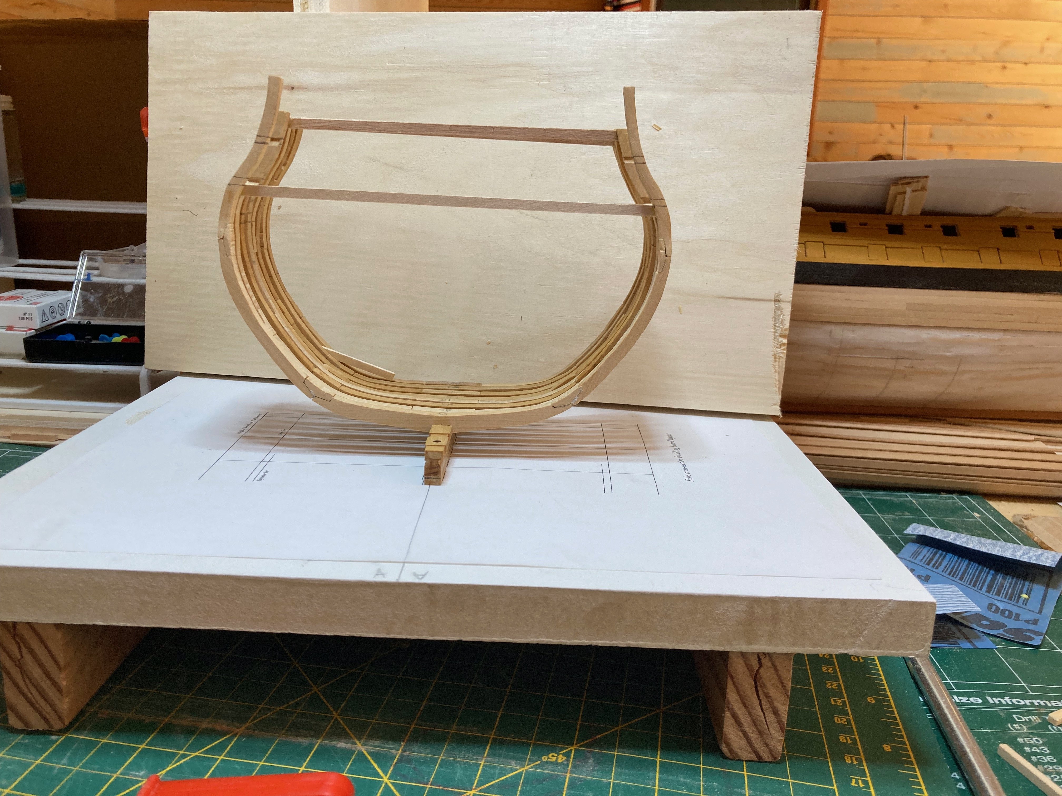
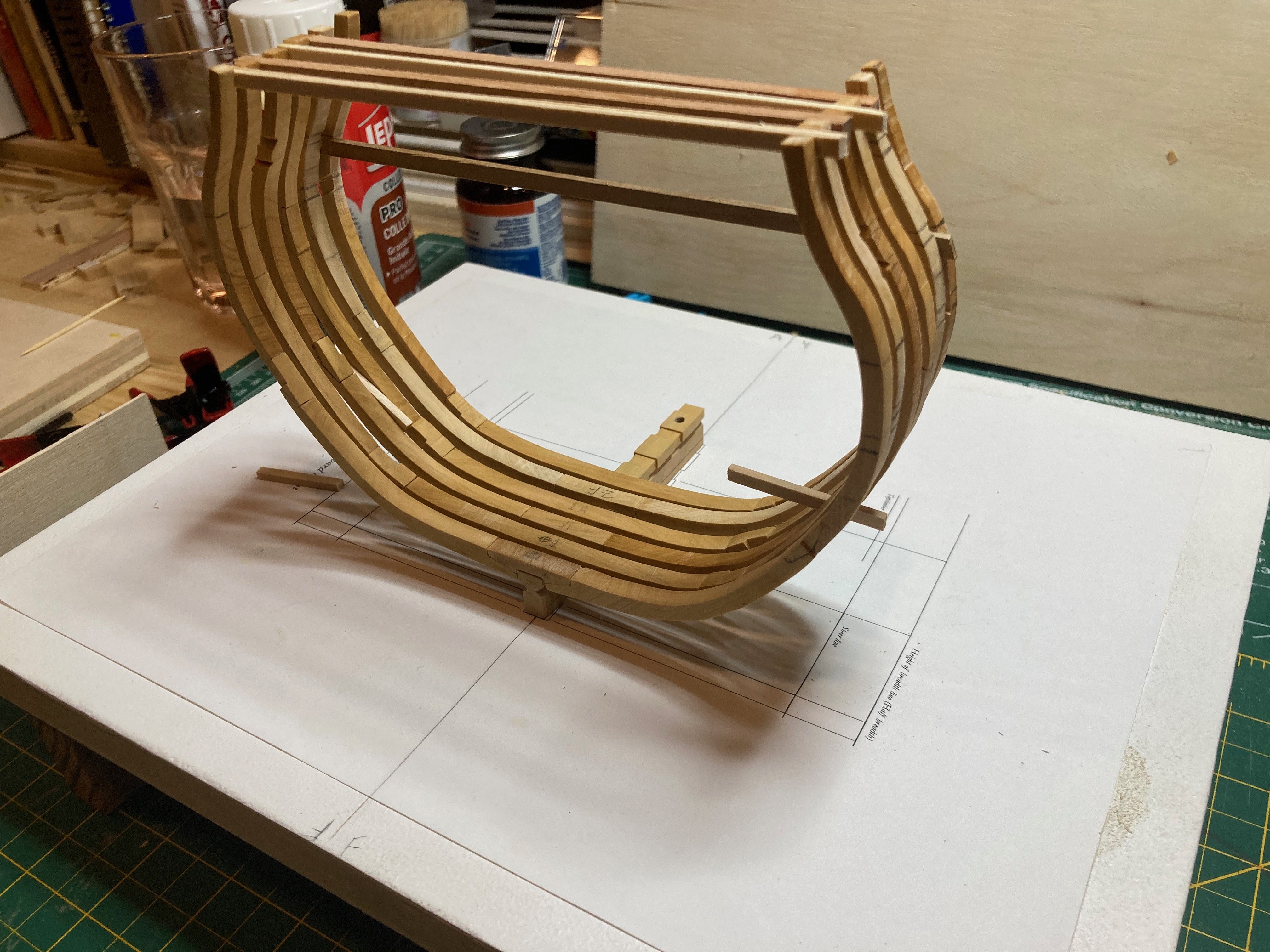
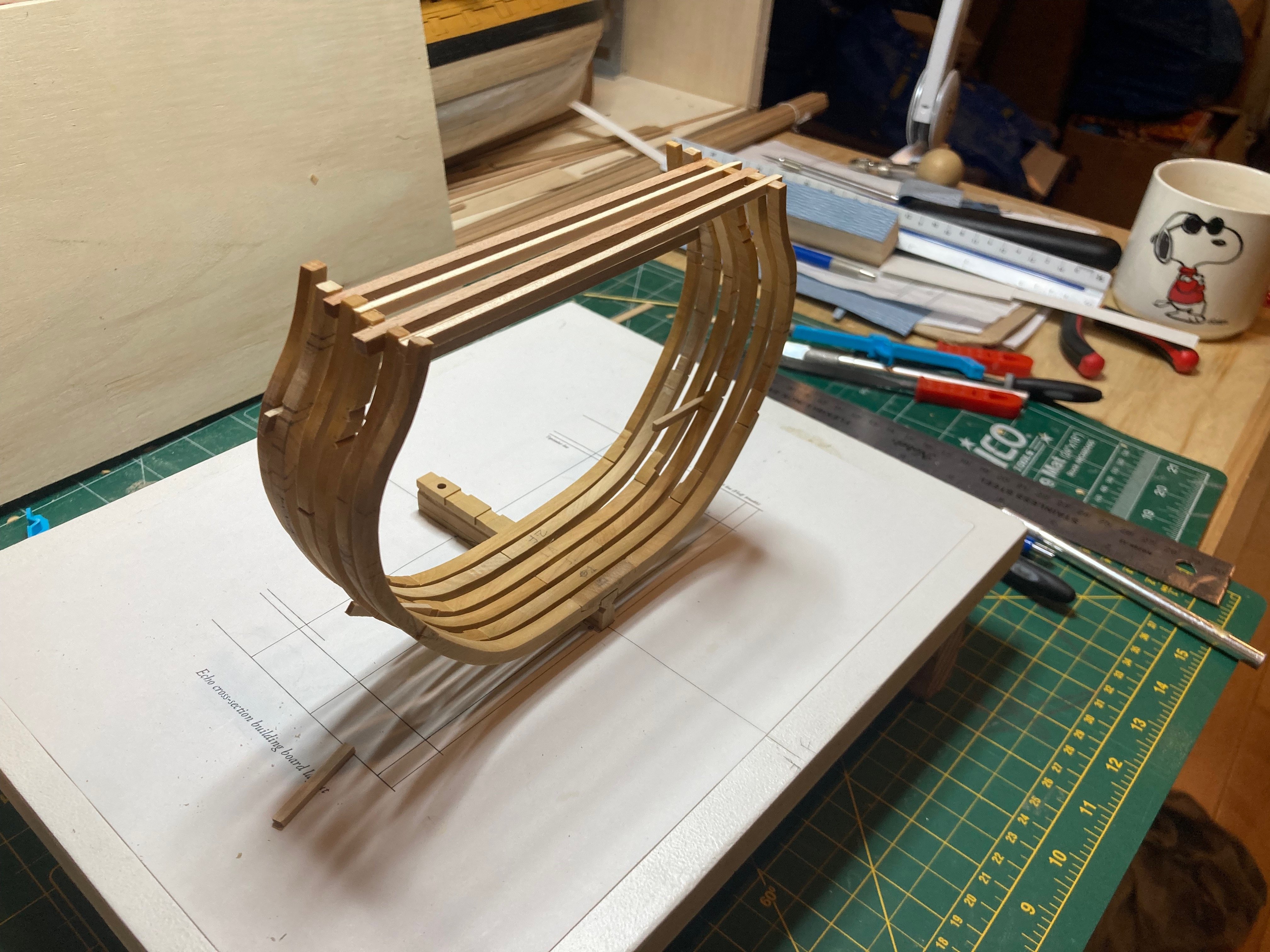
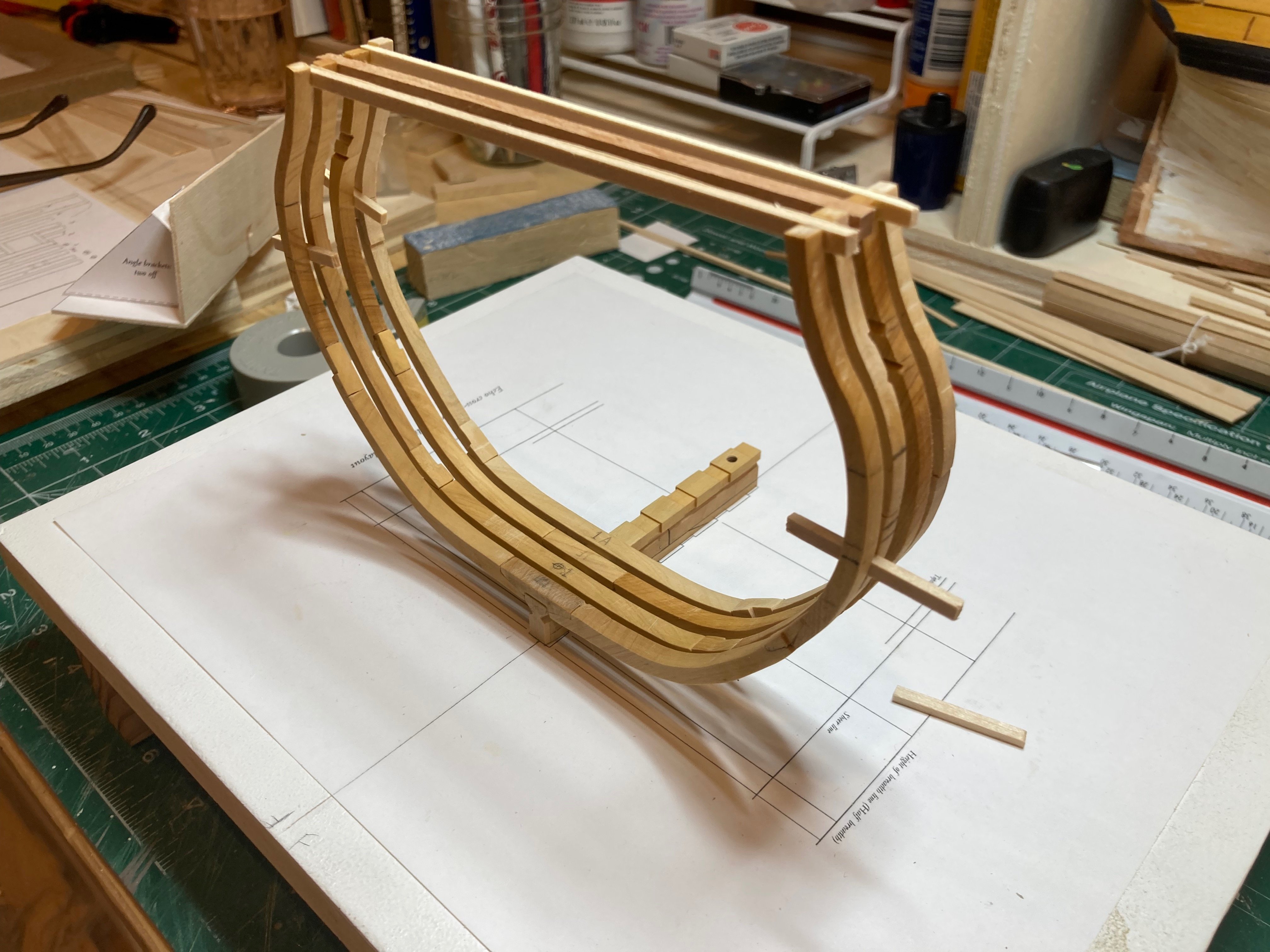
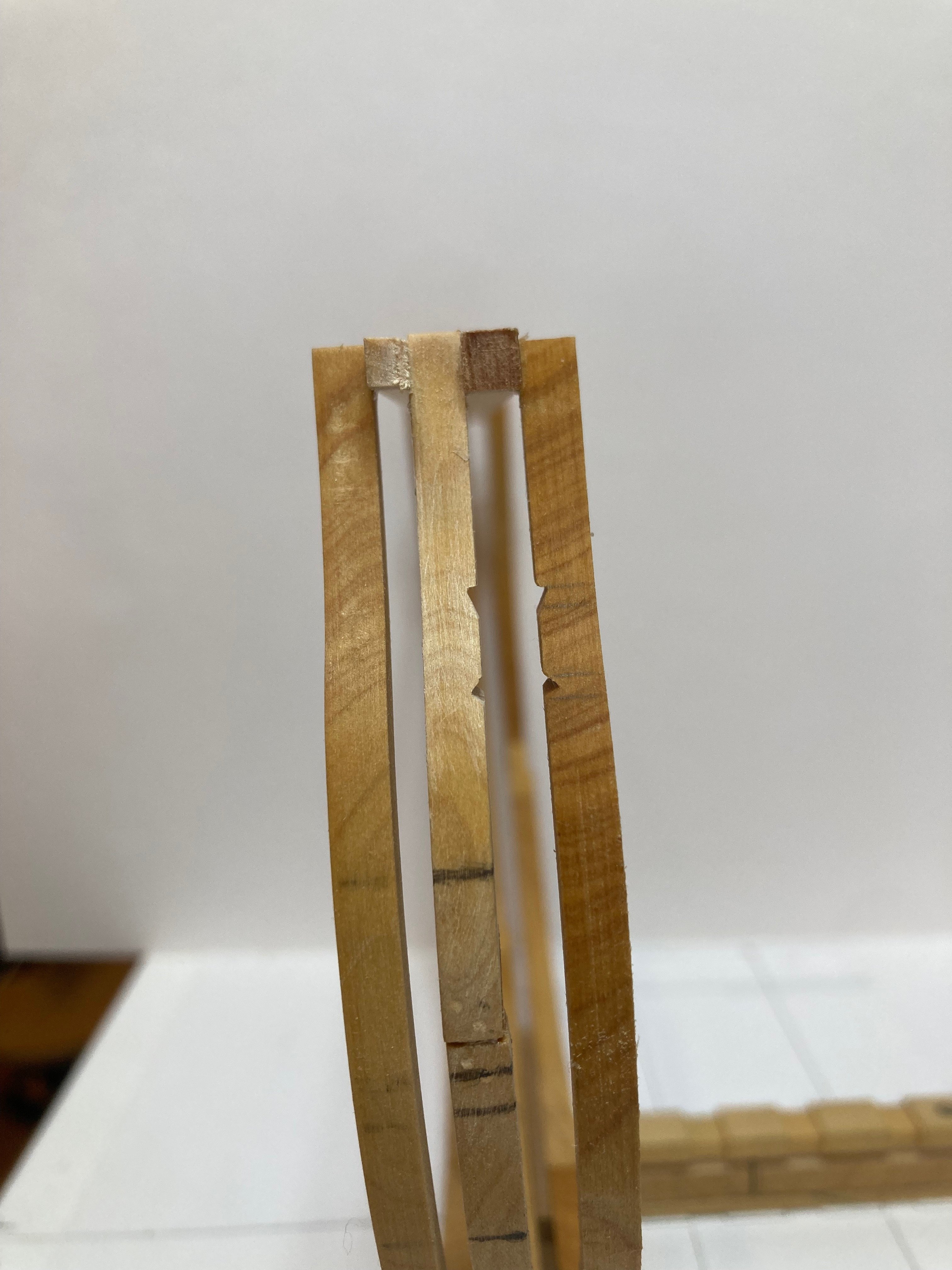
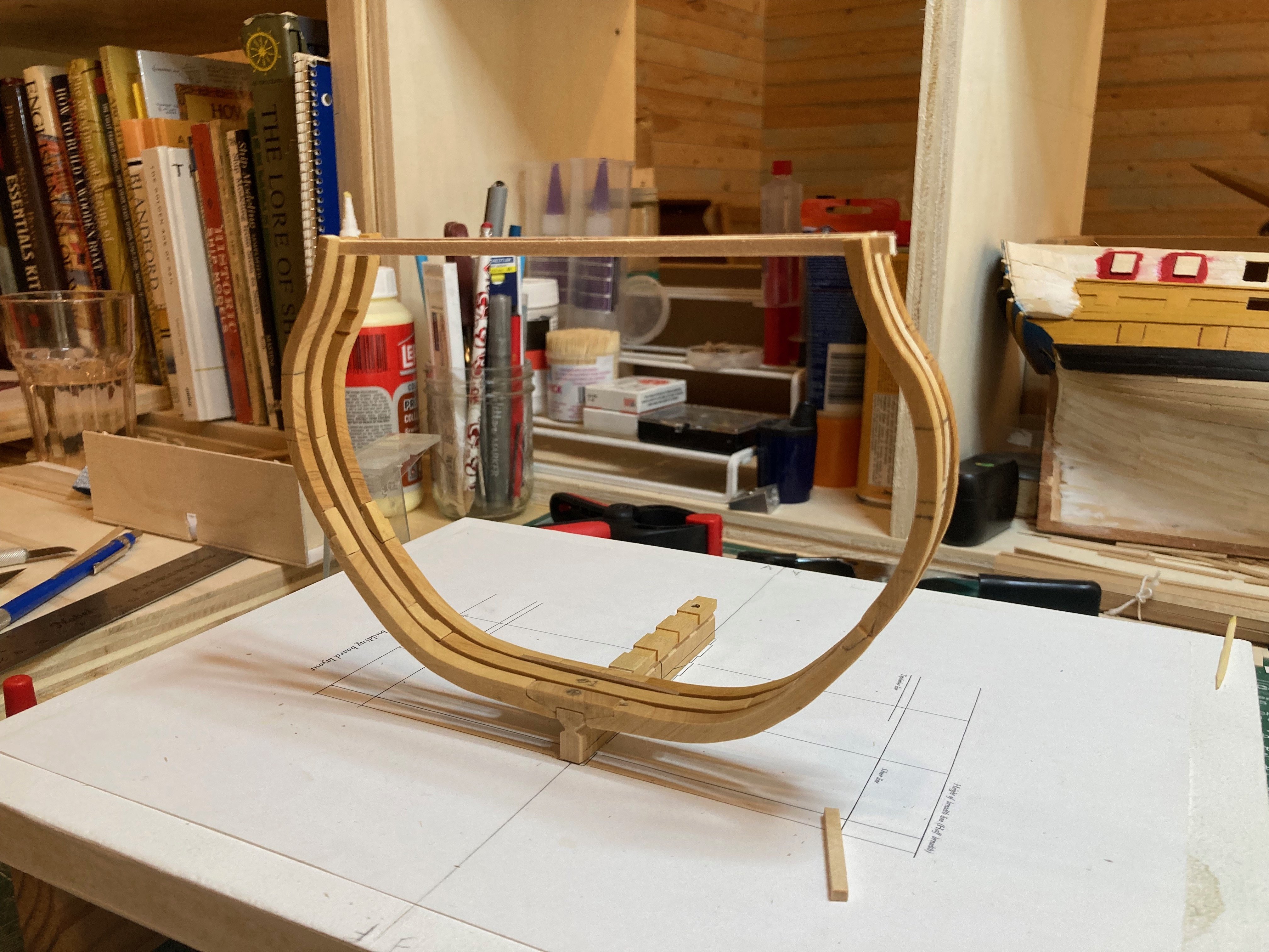
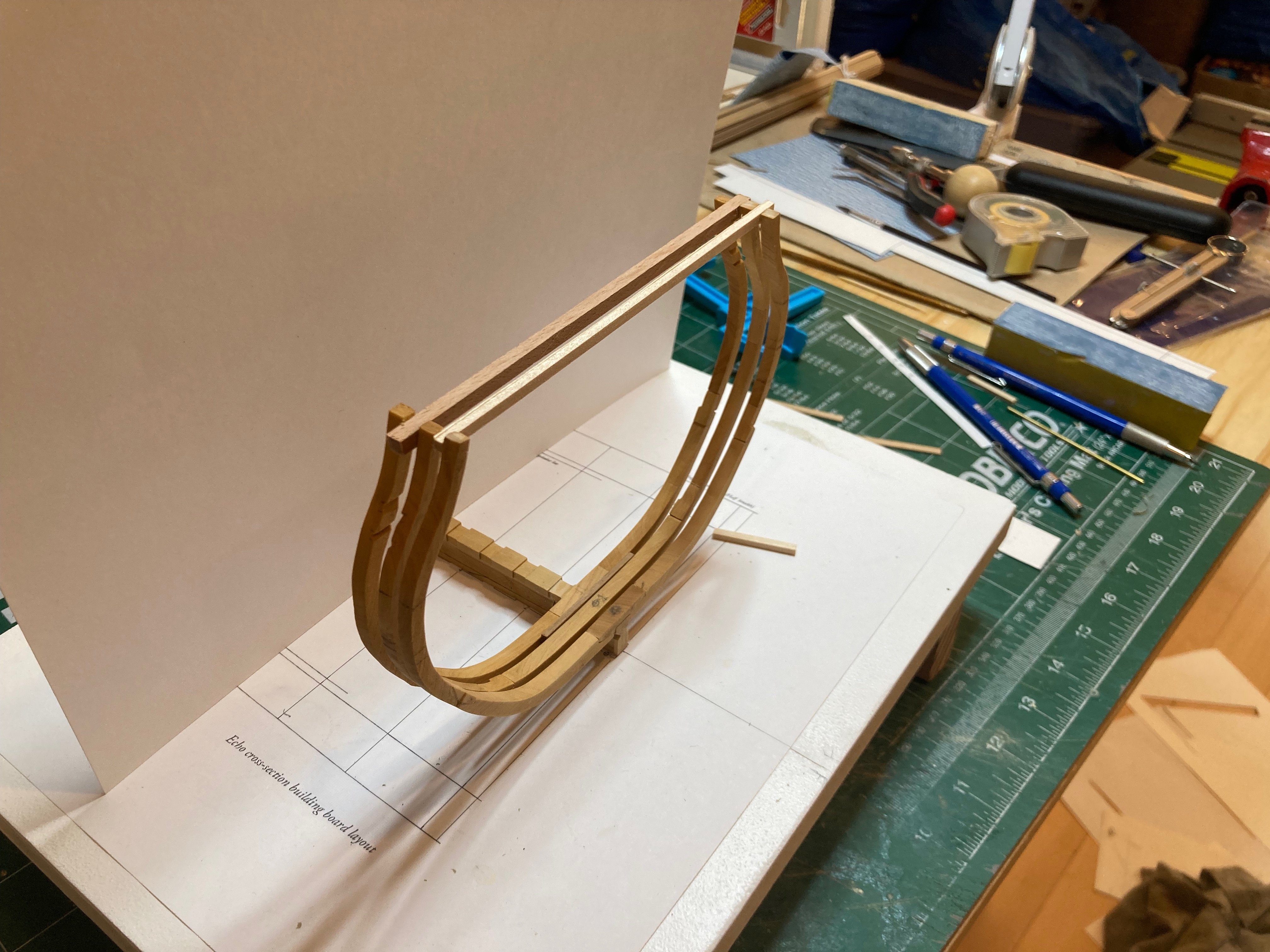
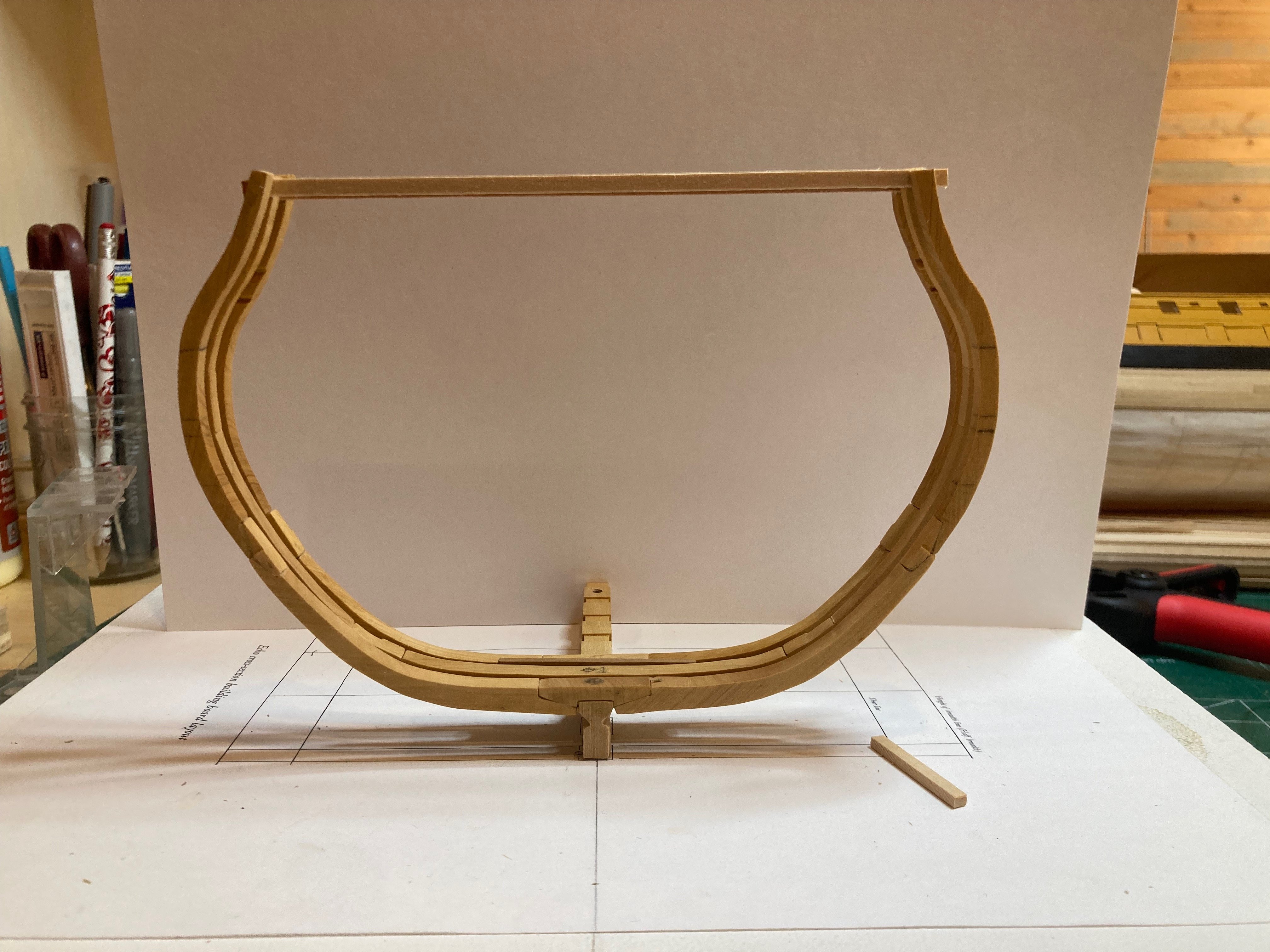
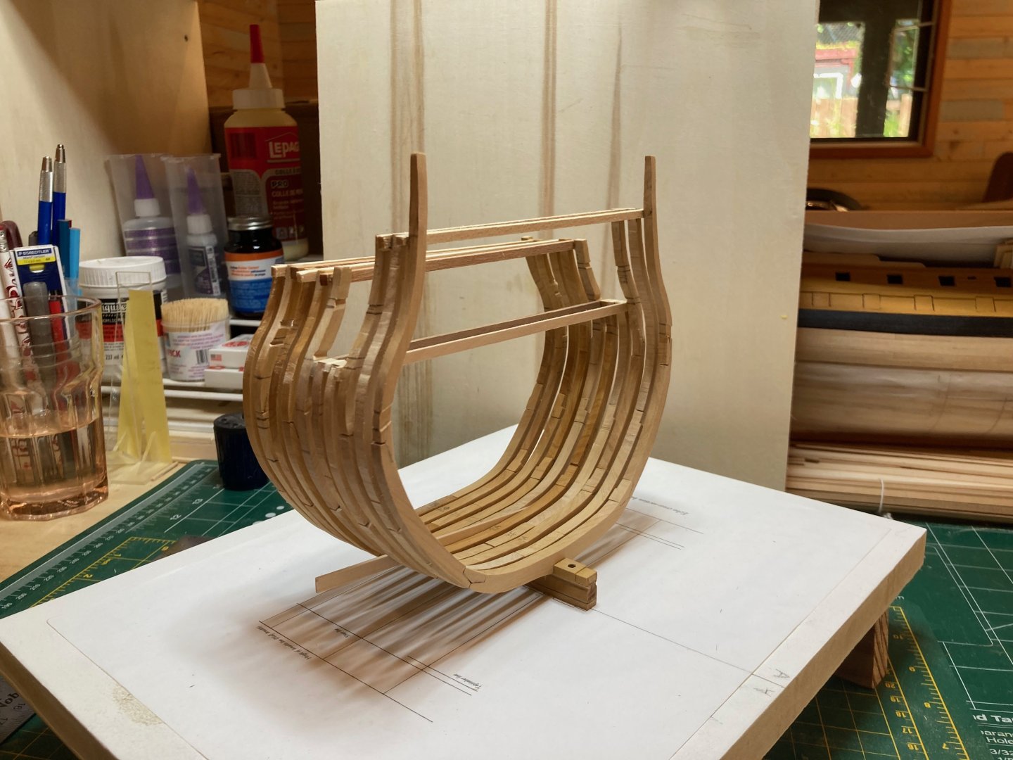
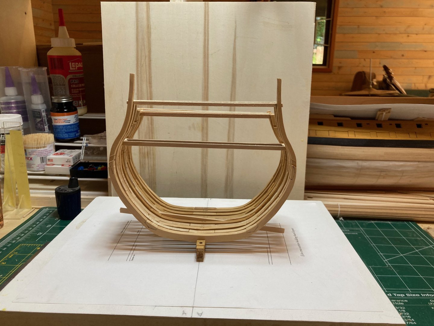
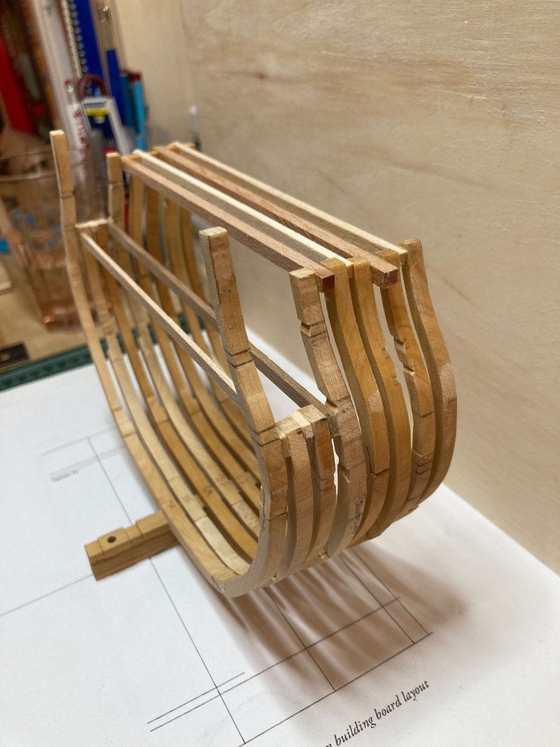
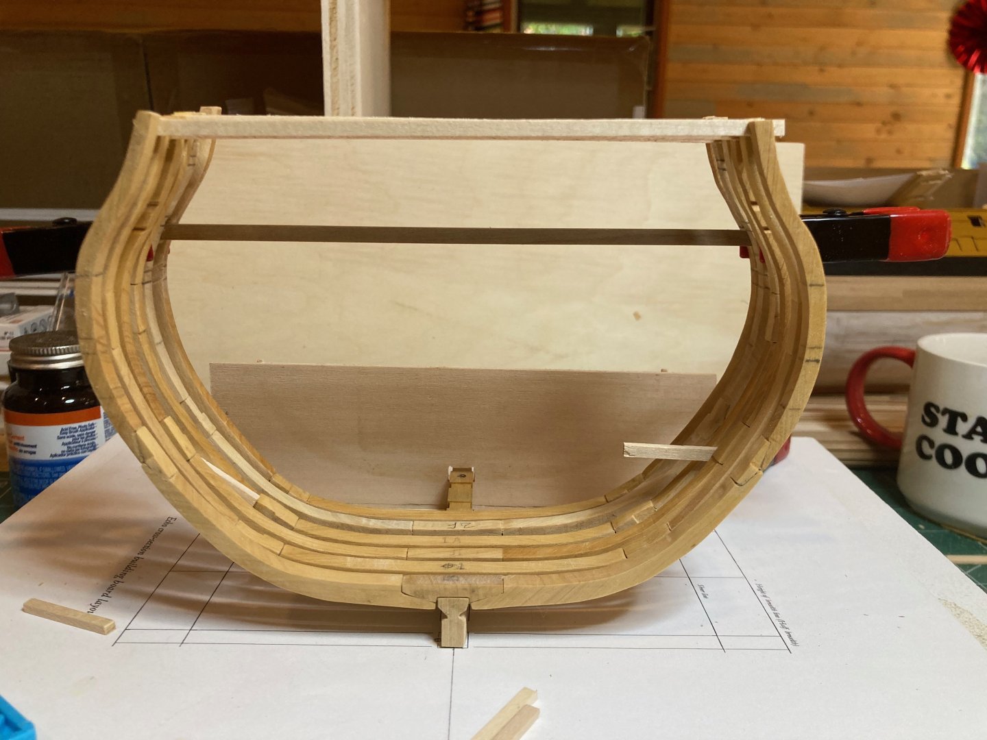
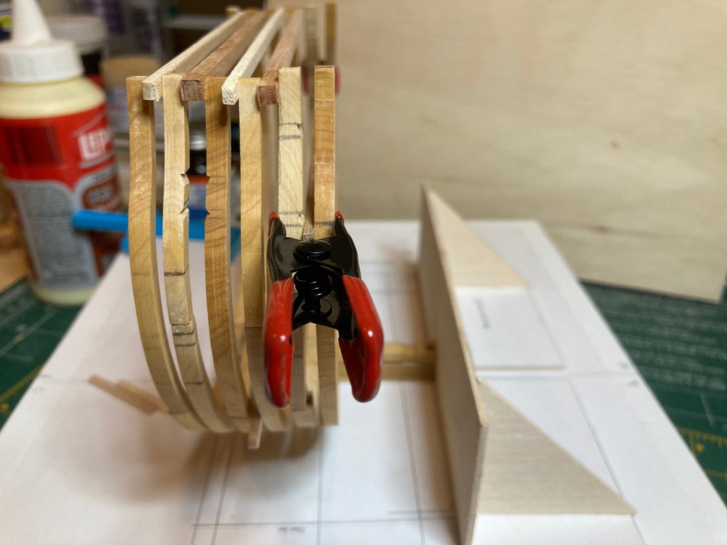
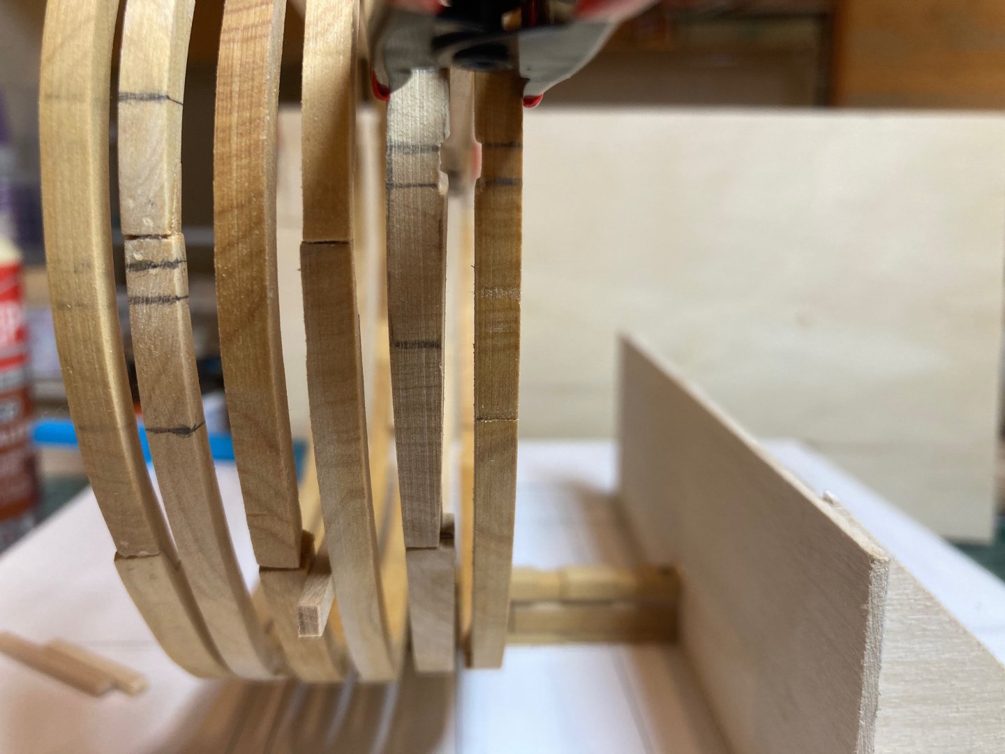
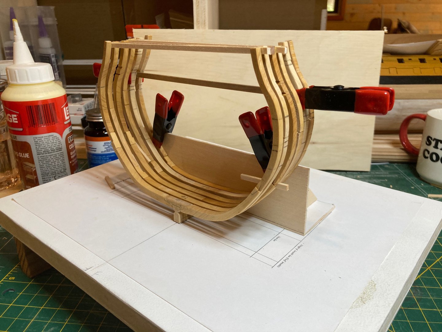
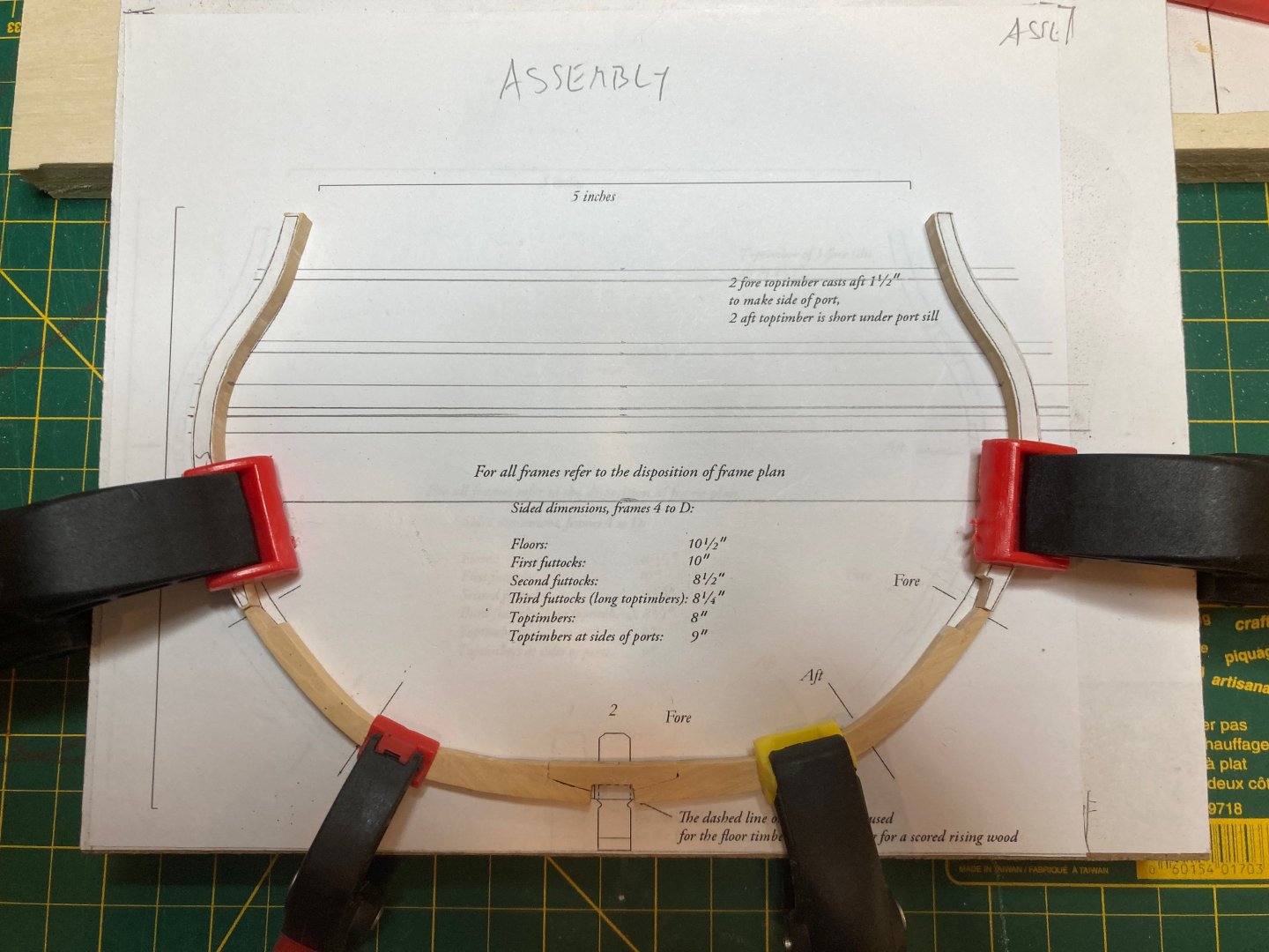
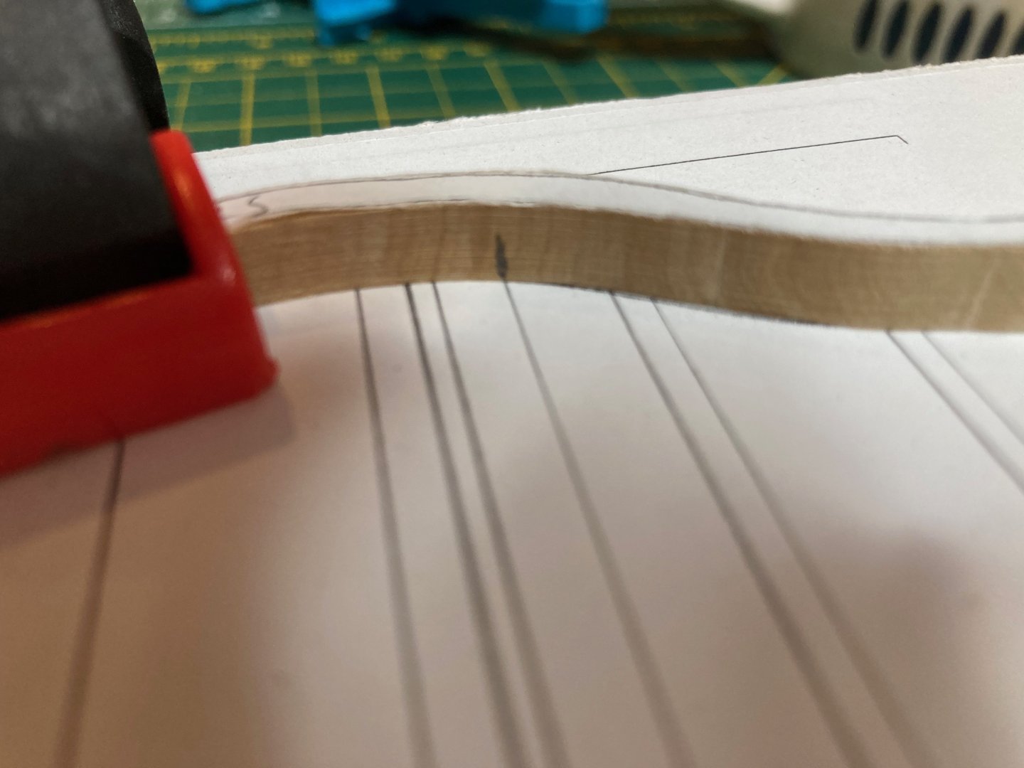
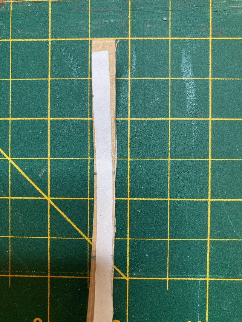
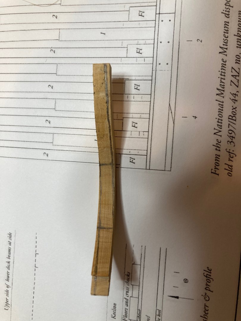
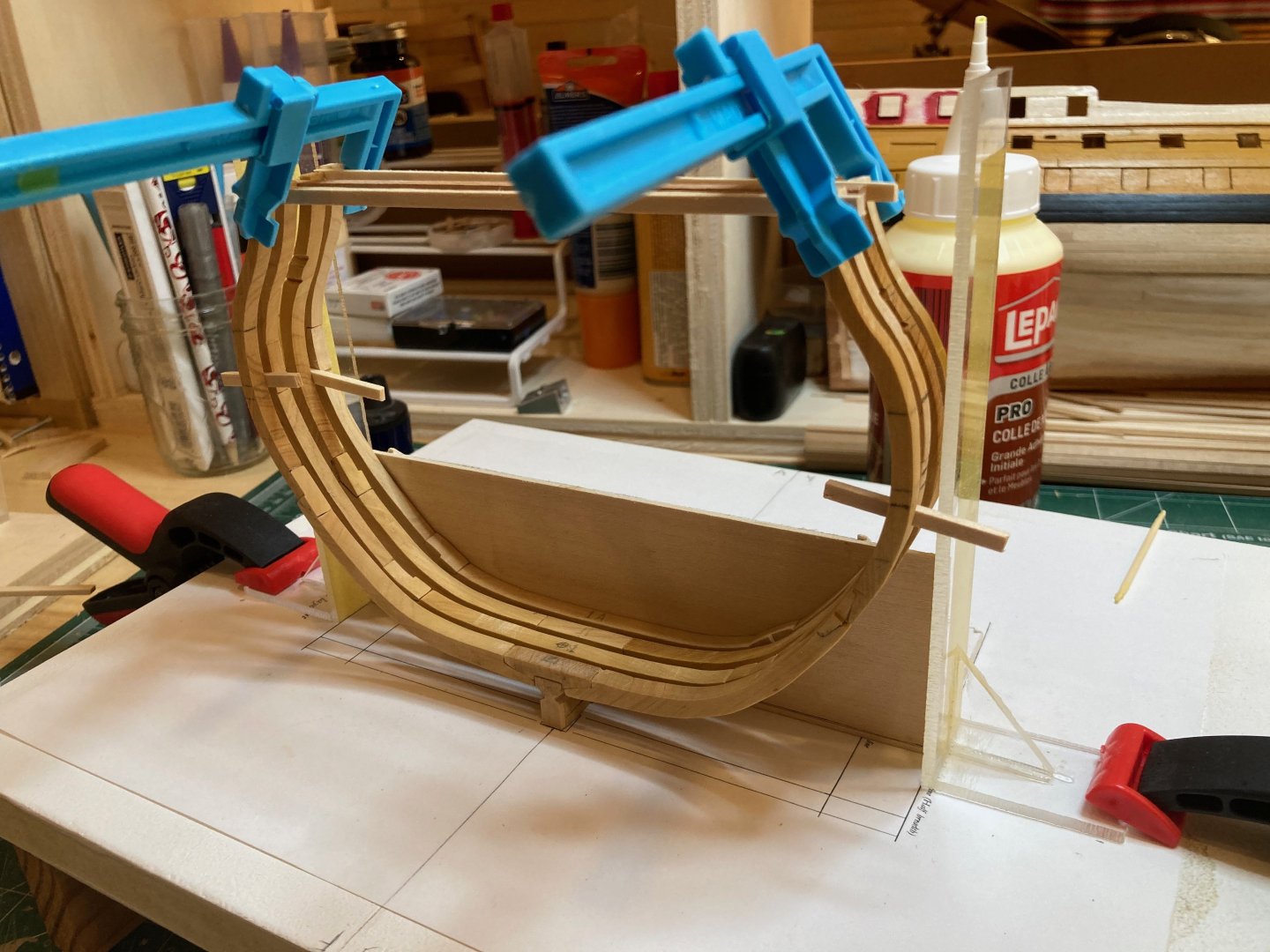
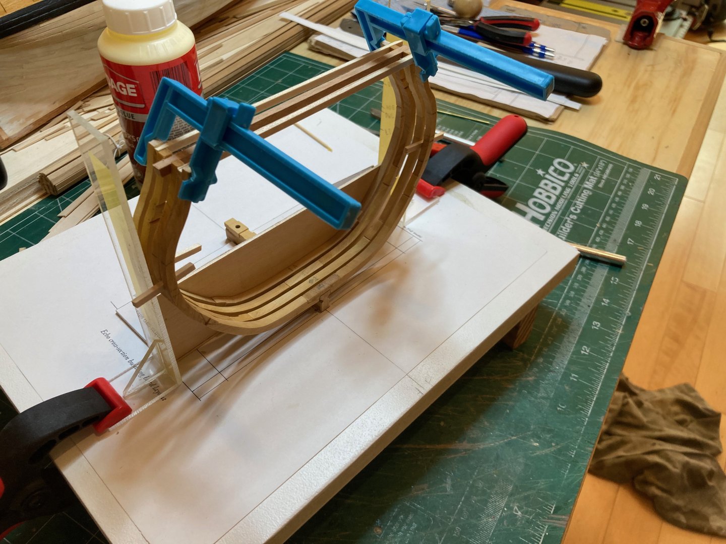
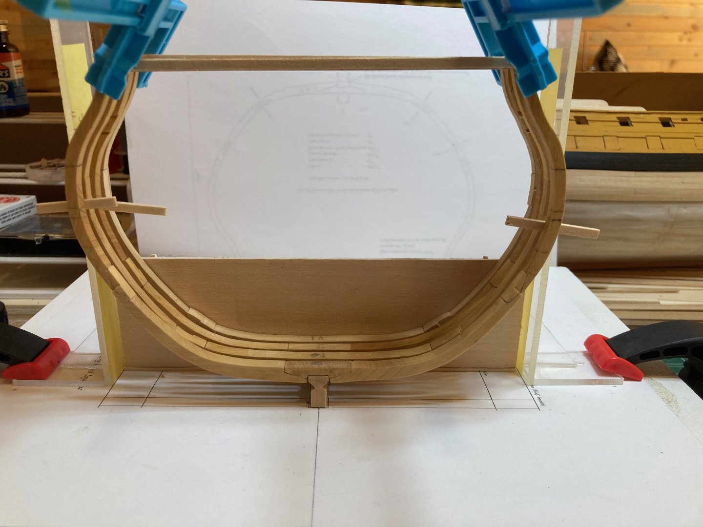
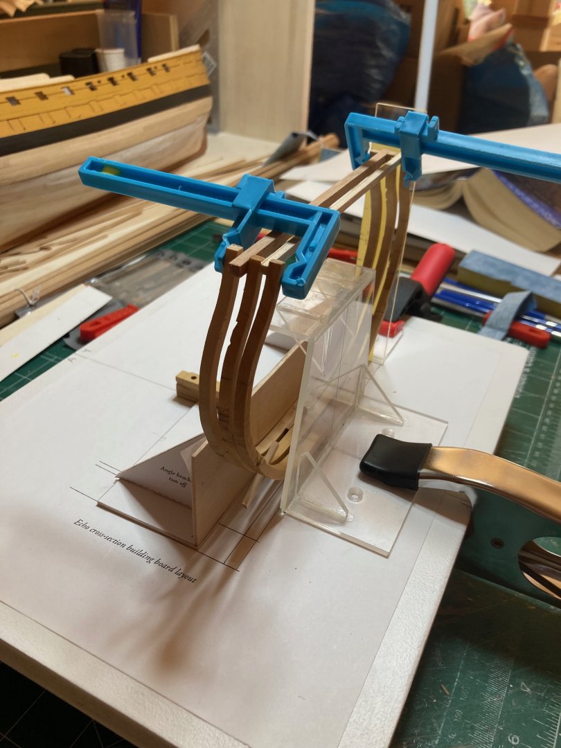
Lots of scrolling on this page!! Hope this post will push the log to page 3 - I imagine people are getting sick of scrolling, as I am..... In any case a final post before we head out on holiday - just a quick one to show frame set 4 completed and raised on the keel. These two frames were very straightforward, though I wish I had added the taper to the toptimber before assembling the frame - I'll do this with 5-aft which has a similar taper. The only other feature is a notch filed into the aft face of frame 4-aft for the pump dale scupper. There was some difficulty getting these symmetrical port and starboard, but in the end they went ok - we'll see much later in the fitting out stage.... In the meantime, here are a couple of photos of the model as it stands. I head back to full time work on Aug. 15, and I'm hoping to be able to complete the framing before then - assembling and mounting frame set 5, adding the gunport and sweep port sills, installing ribands along the toptimbers and making and installing the keelson. I will then be taking a break from this build - hard to say how long, but I think it's time I returned to the Bellona for a while - she's been neglected in the excitement of making frames and I know that once I get through the lower hull planking the real fun can finally begin. Hope all are well and bye for now hamilton


-
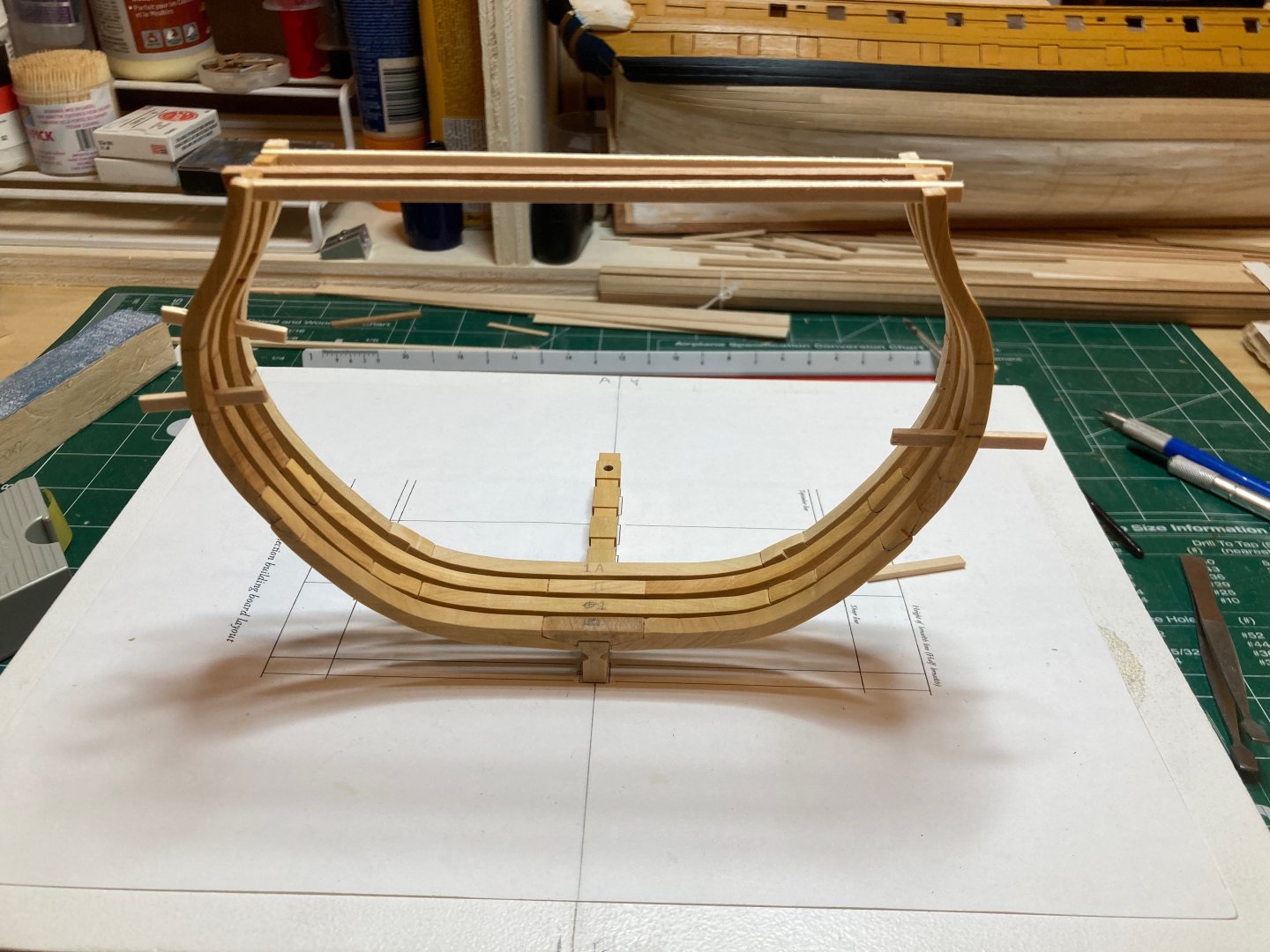
Frame set 3 is now complete and installed on the keel. Together, frame 2F and 3A define the gunport and I've also removed the tops of the toptimbers on 2A and 3F to open this port - the ends of the timbers still need some refining (and all frames need to be completed) before installing the gunport sills and completing the framing of this feature. The work is not perfect! But it has been a lot of fun! I had been dreading crafting the cast toptimber of frame 3A, but in the end (and given the experience of making 2F which has a more subtle cast aft) it was not that difficult. I made 4 templates from copies of the disposition of frame and fixed these to both inboard and outboard edges of each toptimber with rubber cement. I then marked the portion of the toptimber to be cut away, tested for symmetry and used the same method described above for 2F. In the end, this one ended up actually being a little more straightforward since 2F is cast in more of a subtle "S" curve, while this one is cast out from the bottom edge and the top part is more or less a straight run. The trickiest part was refining them for symmetry and this was less tricky than it was very exacting a slow going. I've cut out all the components of frame set 4 as of this morning, and will start refining and assembling them over the next couple of days. We're heading out to the cabin for a couple of weeks of Gulf Island relaxation - beach combing, swimming, paddle boarding, reading and visiting with friends - a nice break from the city but I know I'll be excited to come back to the bench! I have a week more vacation when we return and then it's back to work - I'm hoping to have the framing done by the time work starts up again, but we'll see..... Bye for now and enjoy the photos hamilton


-
Beautiful work on the stern decorations - it is mystifying to me how some can keep their hands so steady as to achieve these effects! I think I would need to clamp my forearm in a vice! hamilton
-
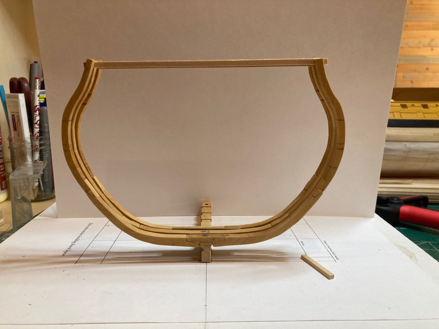
Frame set 2 is now complete and raised on the keel. Frame 2 aft is shortened in line with the gunport and also contains the aft notch for the scupper block (to be added later), so reference lines were drawn for these and the frame was notched out for the scupper block. I added a batten across the aft face of frame 2F at the level of the lower edge of the lower gunport sill and used this to align frame 2A. It will also be useful for bracing the frames when the time comes to remove the upper part of the toptimber to open up the gunport. I won't do this until after I've raised frame 3F, since this one is subject to the same treatment. One photo below shows the notches for the scupper block - the photo makes the it seem out of alignment, but I promise you it is not.... Altogether this is a very fun build. I have been really intimidated by the framing process - having observed others do it so well....but it is a really fun challenge so far - though maybe talk to me when it comes to the deck framing, which seems an even trickier business than this! Bye for now hamilton


-
A question for @druxey if you have a moment..... The scupper blocks that are inset between frames 3F and 3A and between frames 4A and 5F - I'm assuming that these should stand proud of the outboard edge of the frames to allow them to be flush with the main wale....but how are the inboard sides treated? I'm guessing that the pump dale scupper inboard will be covered by the pump dale itself, but how about the "regular" )(not sure how to designate this) scupper? This is a long way off in the build, but working on frame set 3 has put it in my mind..... hamilton
-
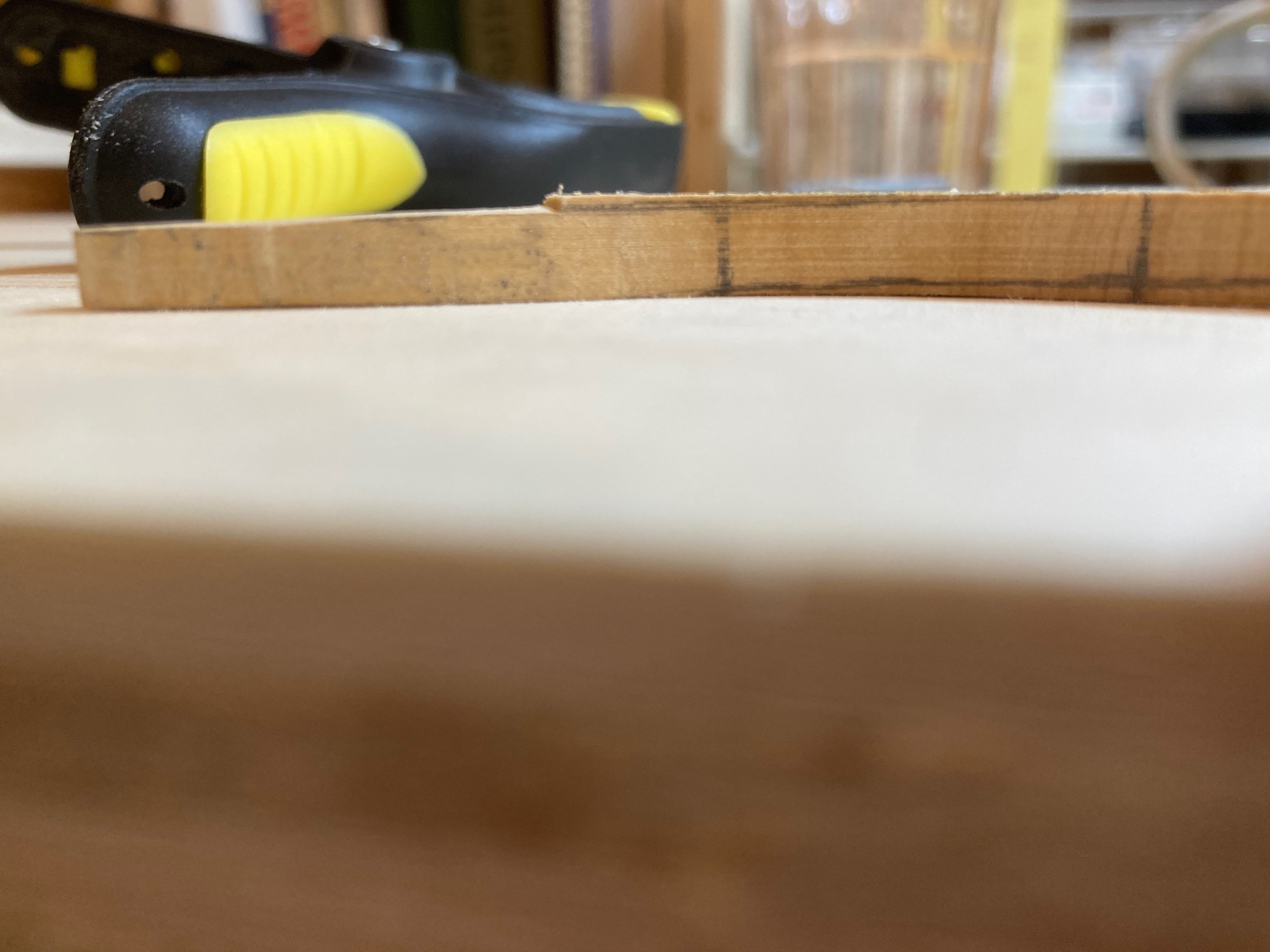
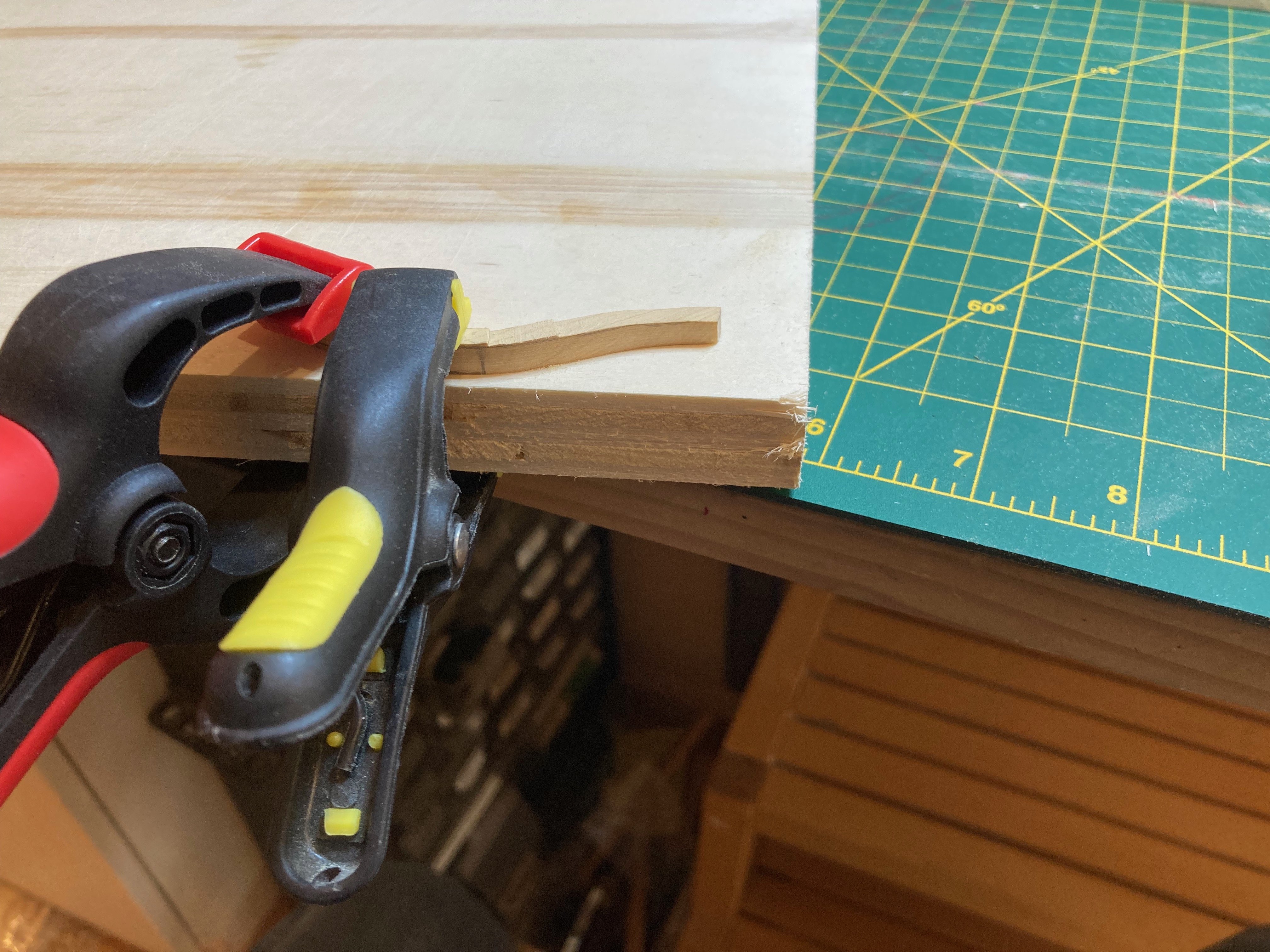
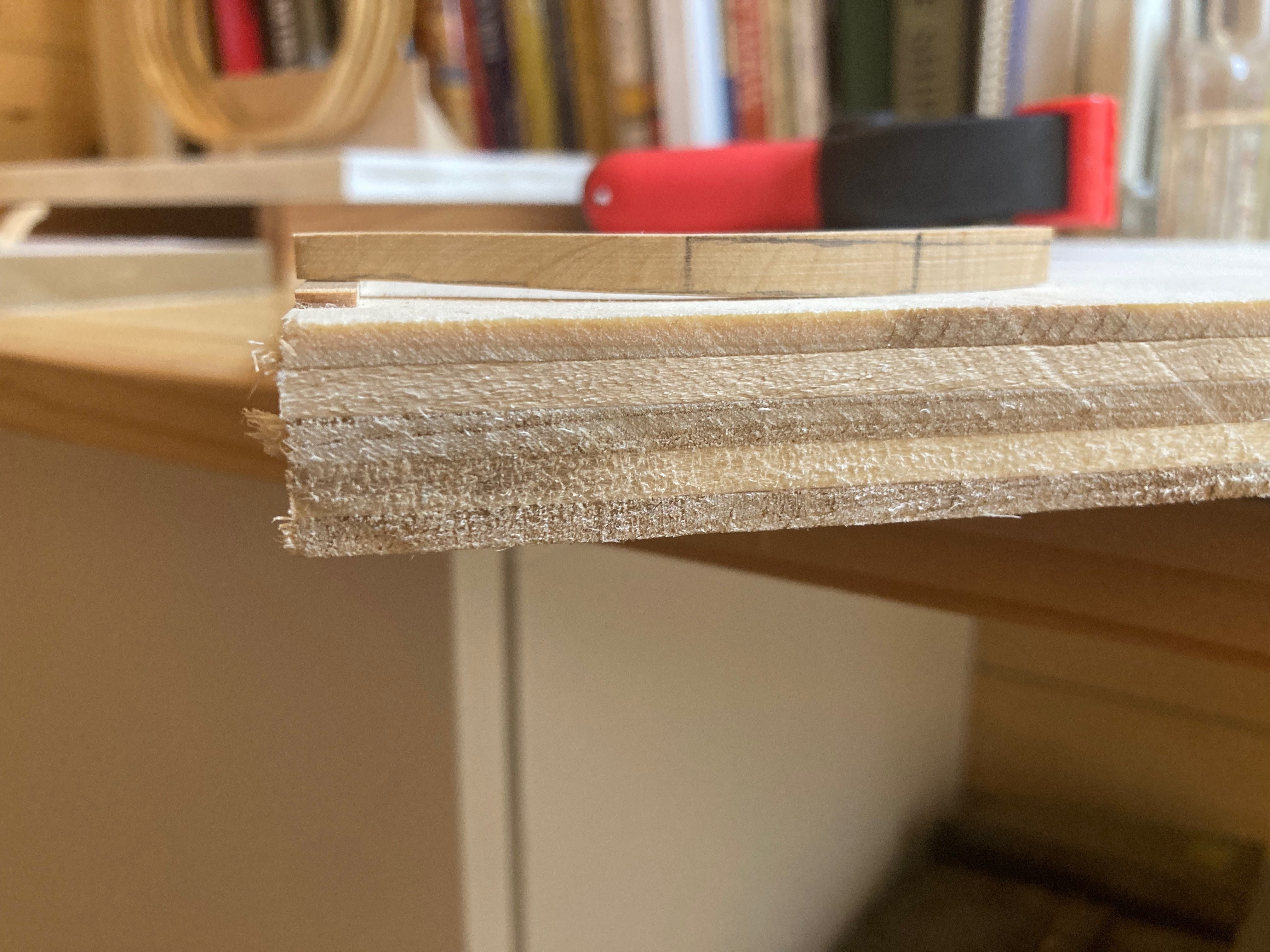
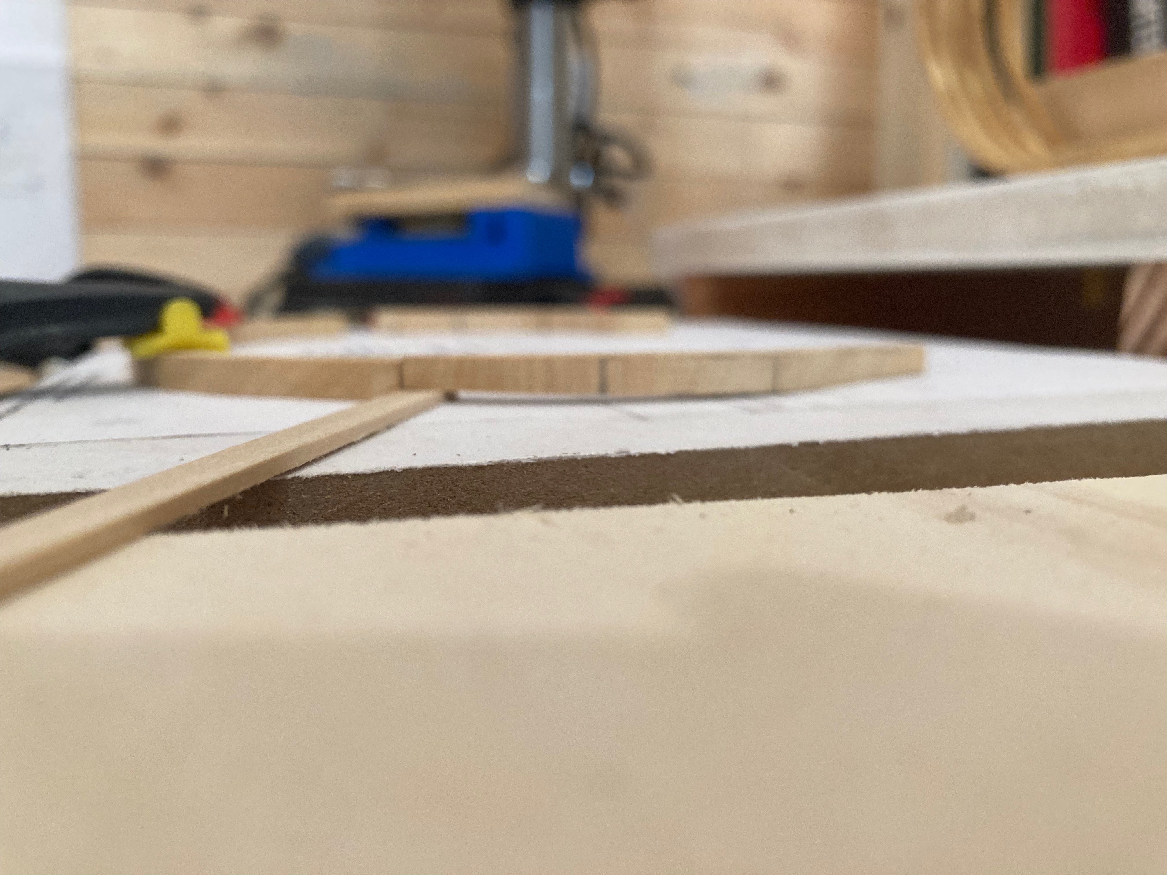
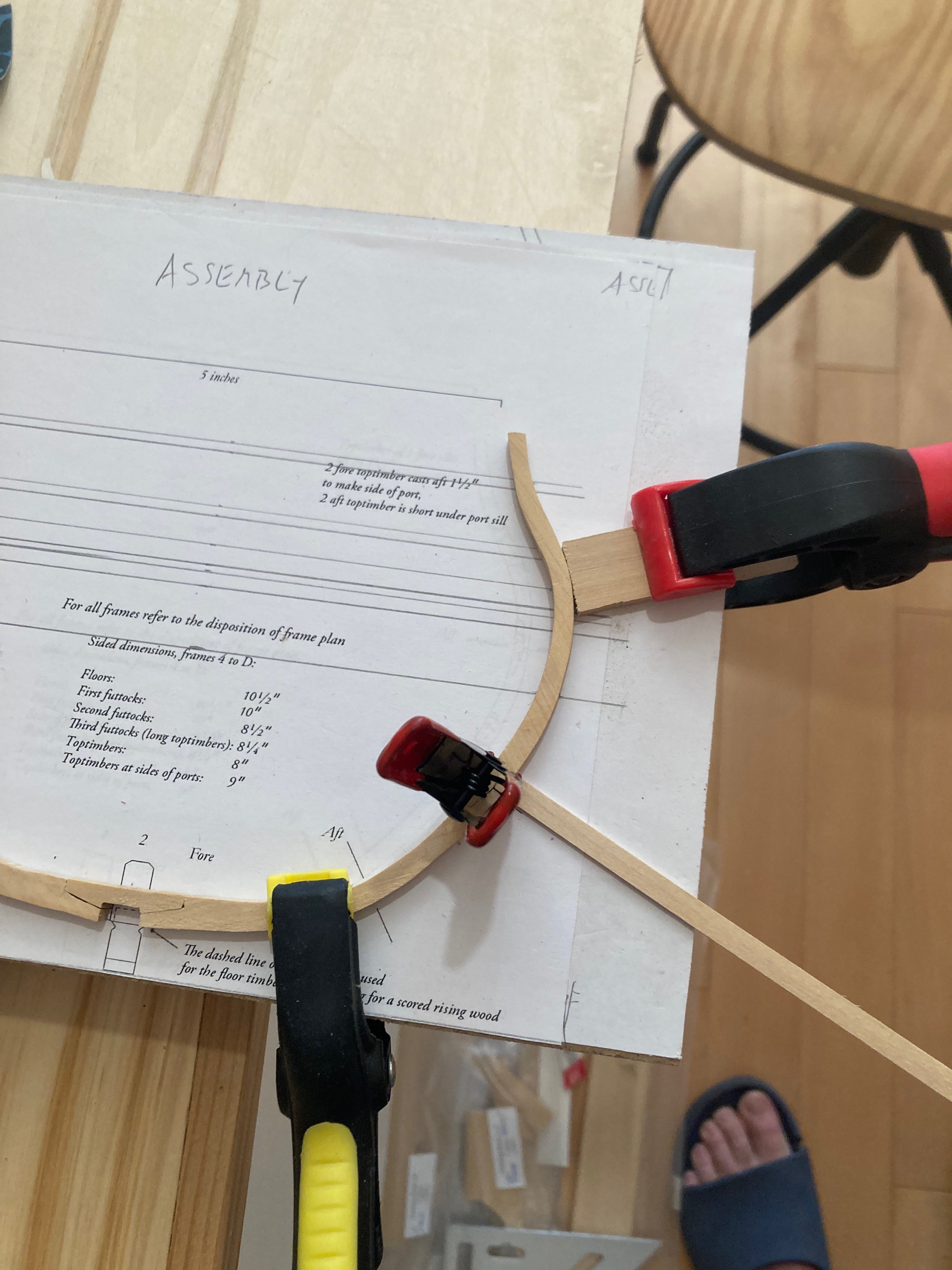
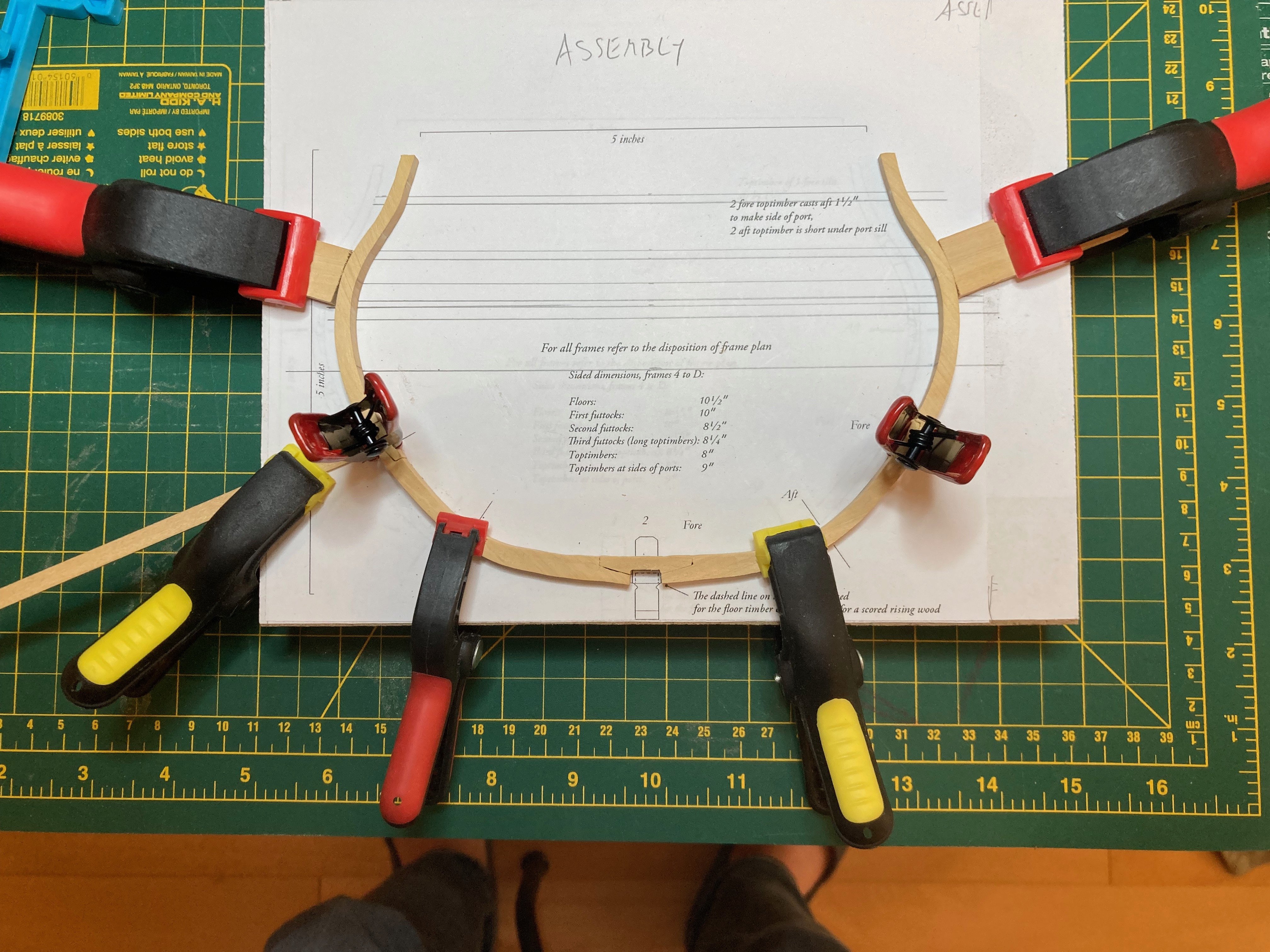
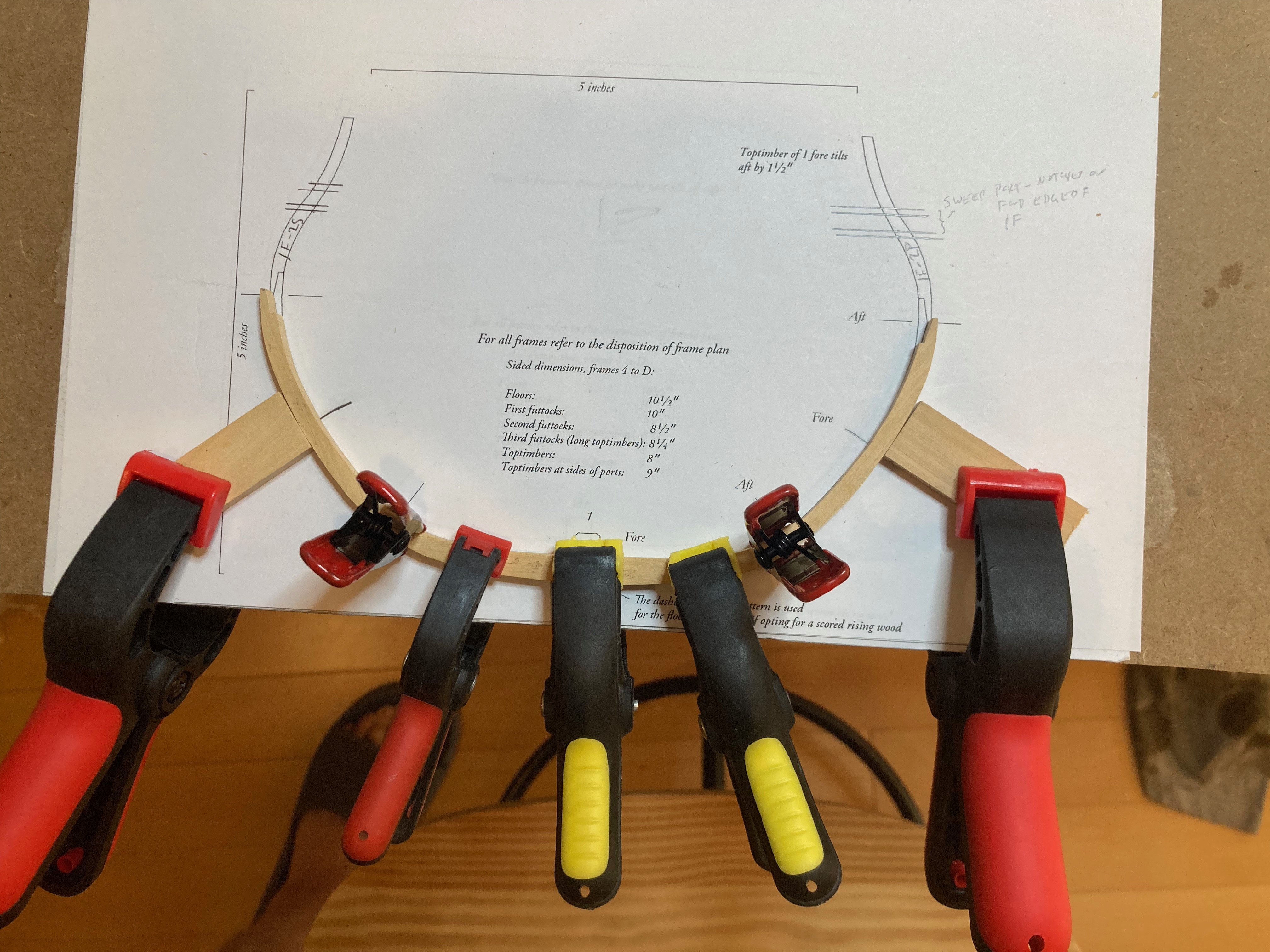
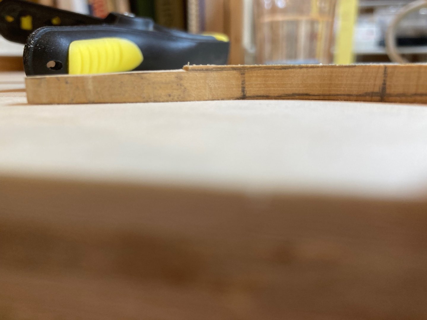
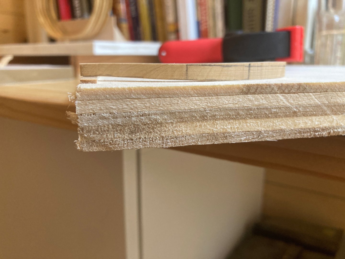
Both frames in frame set 2 have now been assembled and it remains only to mark/cut out notches for the gunport sills and the scupper. This was a challenging process with the cast toptimber of framer 2F, but in the end it was not quite as difficult as I feared it would be and I'm very happy with the results. I do want to take a bit of time to outline the process... The first step was to transfer some reference marks from the disposition of frame drawing to the frame drawing, using tick strips to measure off and square these up. Horizontals were drawn across the frame drawing to ensure symmetry athwartships. I then clamped the frame components in place on the drawing and transferred the marks to the outside and inside edges of the toptimber. I then cut a template from a printout of the dispotion of frame drawing - actually 2 to tack onto the outside and inside edges of the frame, being careful to orient them correctly! These were tacked with rubber cement and the areas to be cut down marked onto the frame piece. This was a little finicky since the disposition of frame drawing does not accout for the outward curvature of the frame itself, resulting in templates that are short compared to the toptimber piece itself. This was not too difficult to correct for, but required a lot of back and forthing from plans to part. The area to be cut was marked out on both inside and outside edges. I then clamped the piece to a slab of 3/4" ply and, using a #11 blade stated gradually removing the wood by making a cut down to the line, slicing wood off carefull edgewise from the face of the piece to that cut and then using sanding block and file to clear out the excess material. I did a little bit at a time, following the gradual shallowing of the cut and then sanded the surface down smooth. To cut the other side, I glued a small strip of basswood of an appropriate thickness to the plywood slab to accomodate the cutaway I made previously and to straighten the piece so I could remove material on the other side using the same technique described above. This took a bit of time and care, but worked out ok in the end. And now I have my first properly cast toptimber! If I can get a bit of time tomorrow I'll notch the frame out for the elements described above and then raise the frames on the keel....fun times! Enjoy the photos and happy modelling


-
It's hard to write and wipe the drool off my chin at the same time! Saving my shekels now..... hamilton
-
Thanks TMJ! This bolsters the plan I had in my head but because I've never made a plank-on-frame model before I wanted to test the waters with the community a bit! Thanks again hamilton
-
Thanks Druxey - it's more the actual cutting away that is giving me the nerves.....but the plans and practicum, in addition to Vol 1 of the Swan series have taken a lot of the mystery out of things - I think in this instance it's more that a lack of practical experience at this approach to ship modelling makes it seem really daunting - I've decided to cut a couple of extra top timbers to practice on and get a feel for how to achieve the proper result hamilton
-
Frame set 1 is now complete and installed. Frame 1-aft was very straightforward - the last such frame for a while....(see photos below) I feel like constructing the first 4 frames, while challenging, is kind of a like a tutorial to get you used to the process - with a couple of little quirks thrown in (like the cast toptimber of frame 1 forward). From here, though, things seem to get much more difficult, with a much more significant and complex cast to frame 2-forward and frame 3-aft and the gunport to manage between these....I spent today making templates for the components of frame set 2 - using 11.5" stock for the toptimbers of the forward frame to accommodate the cast aft. It's a bit of a mystery to me how to achieve the cast....I had thought I could do this using the belt sander, but given the curvature of moulded dimension of the frame, this would be very difficult to get an even result in the cast along the sided dimension.....my feeling is that taking a template of the sided dimension from the disposition of frame drawing and having at it with some sanding blocks will likely be the way to go....I may clamp the part in the bench vice with the sided dimension facing upwards to make the process a little easier, but I am open to any and all suggestions on how to approach this...... In any case - there's other work to do before turning to these cast toptimbers so I'll dig into that before facing this challenge! Bye for now hamilton


-
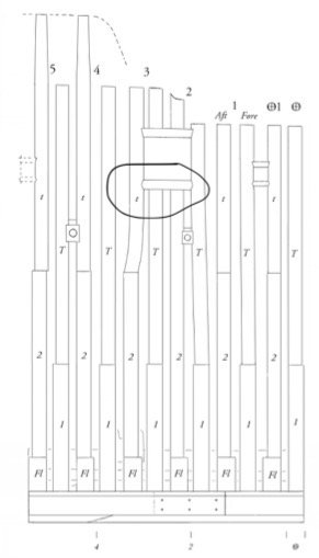
Thanks for the response TMJ, but no - I'm talking about chopping the frame down to lay on the gunport sills and what is the best way to approach this. Here's the photo again with the area highlighted..... hamilton
-
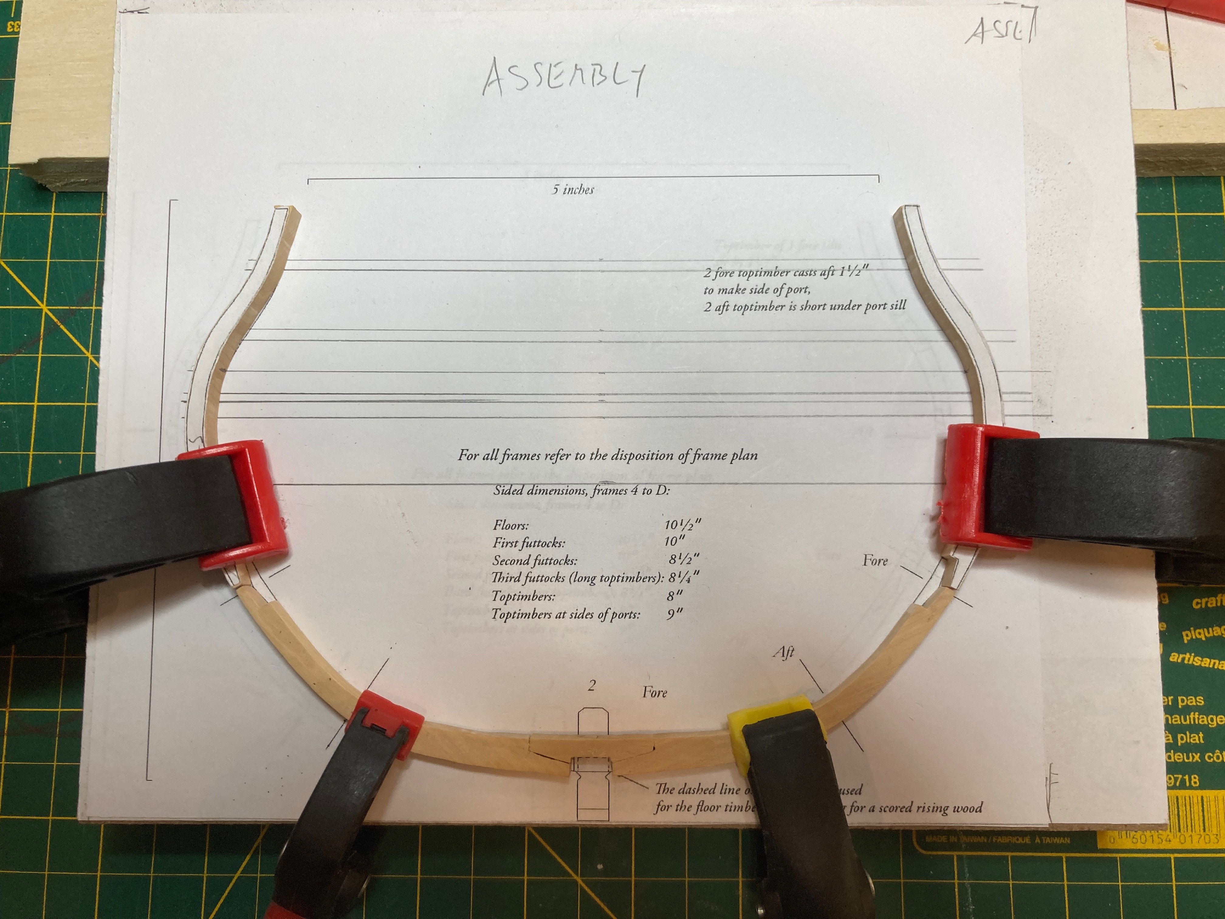
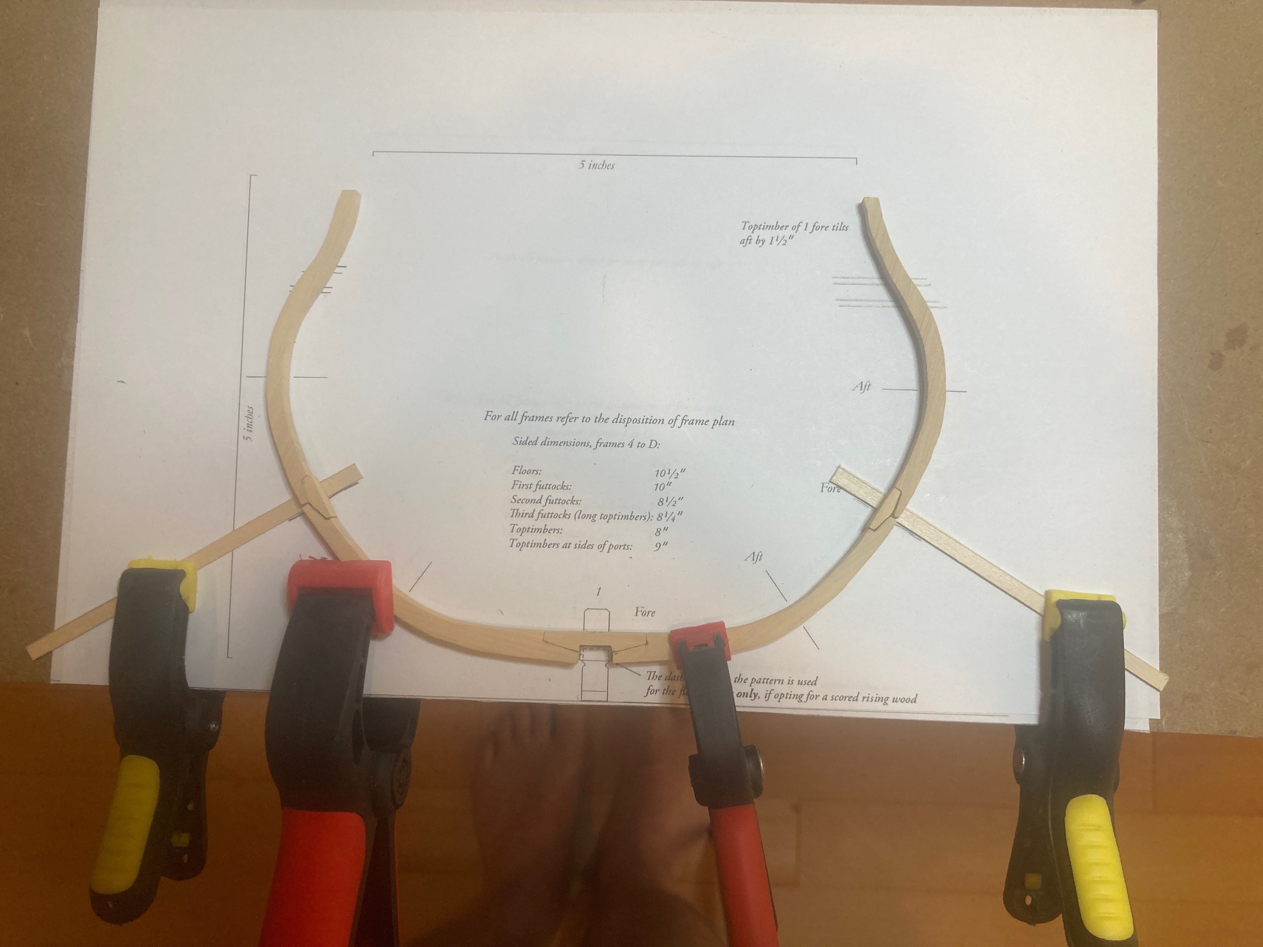
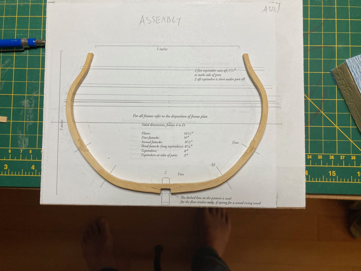
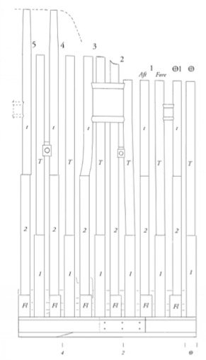
Hi there: I'm working on the Admiralty models HMS Echo cross-sectional model and had a question about how to cut the toptimbers out to frame the gunports. It seems to me there are at least two possible approaches, and I'm hoping to hear from those more experienced than me how best to approach this (understanding that "best" is both subjective and relative).... 1. Complete all frames of the cross-section and then cut the frames off appropriately for the gunports. This method benefits from the strength provided by having all frames in place and with battens added at the top of the toptimbers - though to my mind it seems pretty tricky to cut away the frames even with a small keyhole saw..... 2. Shorten the frames that fall in line with the gunport as they are added to the model, reserving the toptimber pieces for the extensions above the gunports - this seems easier in terms of cutting away the frames, but I wonder if there are difficulties that my lack of experience is hiding from me if I go this route.... I hope the question is clear......Here is the disposition of frame drawing for clarity - the frames in question are 2-aft and 3-forward. Thanks in advance for any help you can provide! hamilton
-
yes, Druxey - this is easier to see in the photos than on the model - there is a definite roundness to the inside corners that needs correcting...fortunately the files are small enough to get in there...added to the lengthening list!! hamilton
-
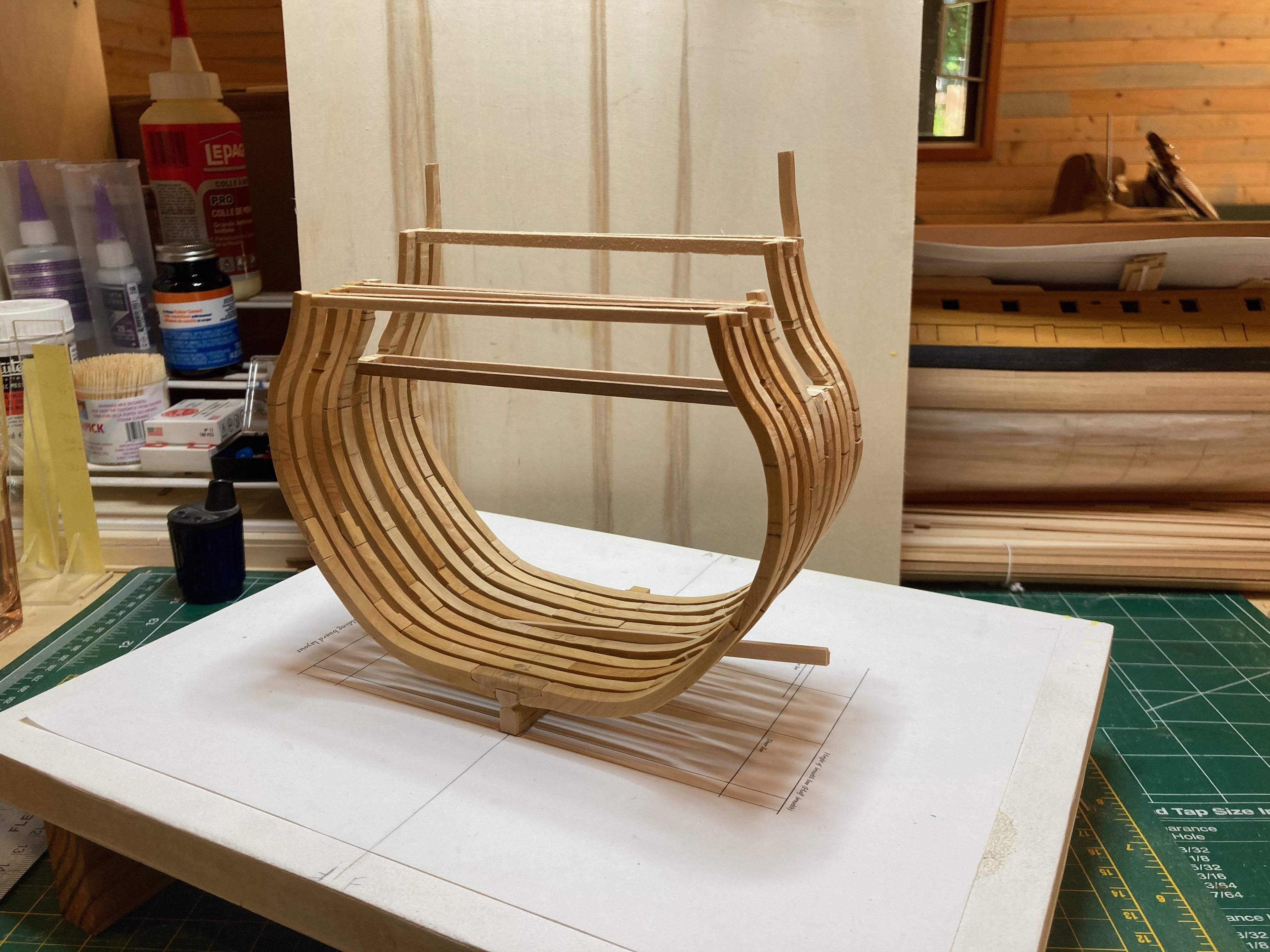
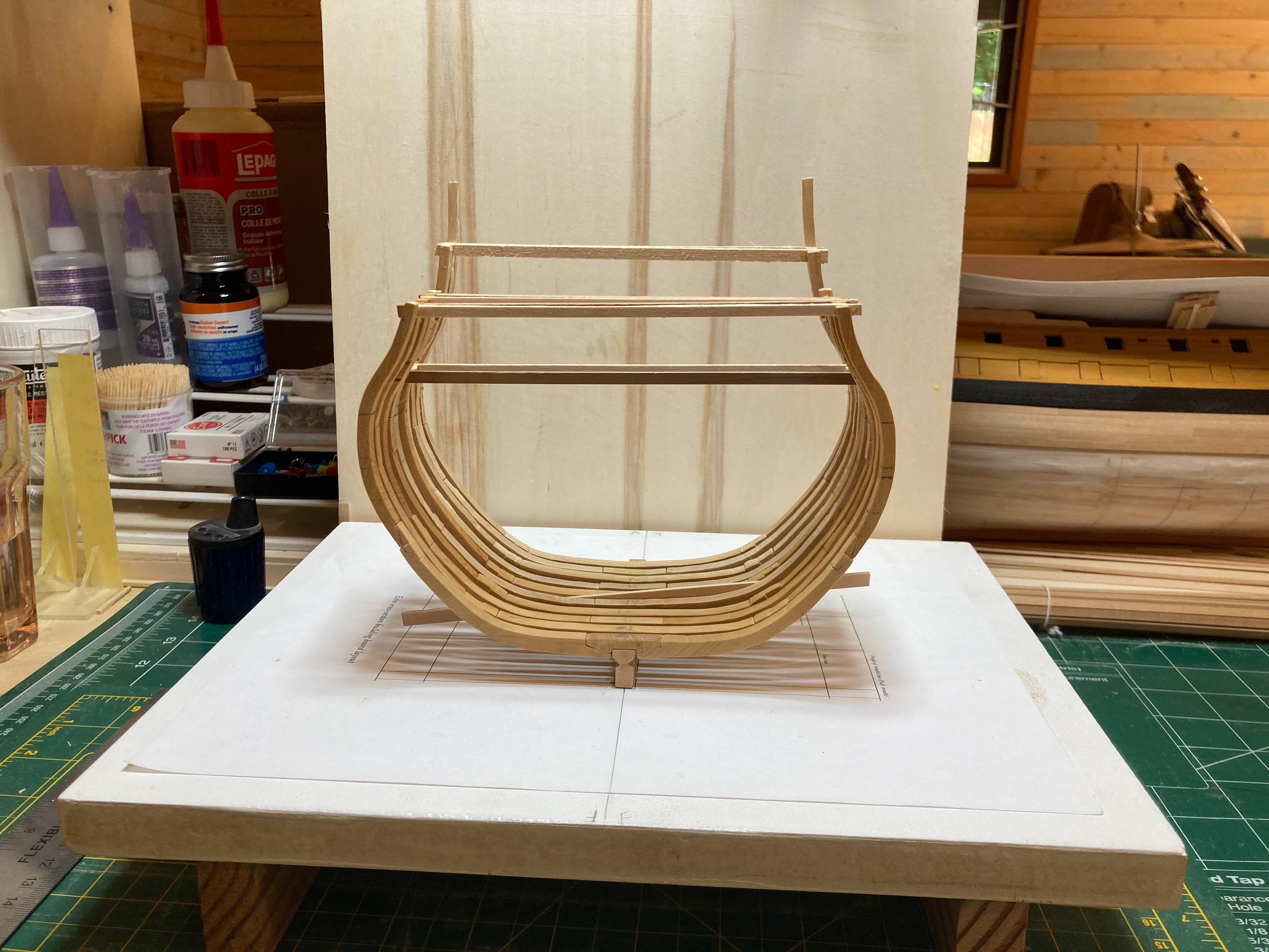
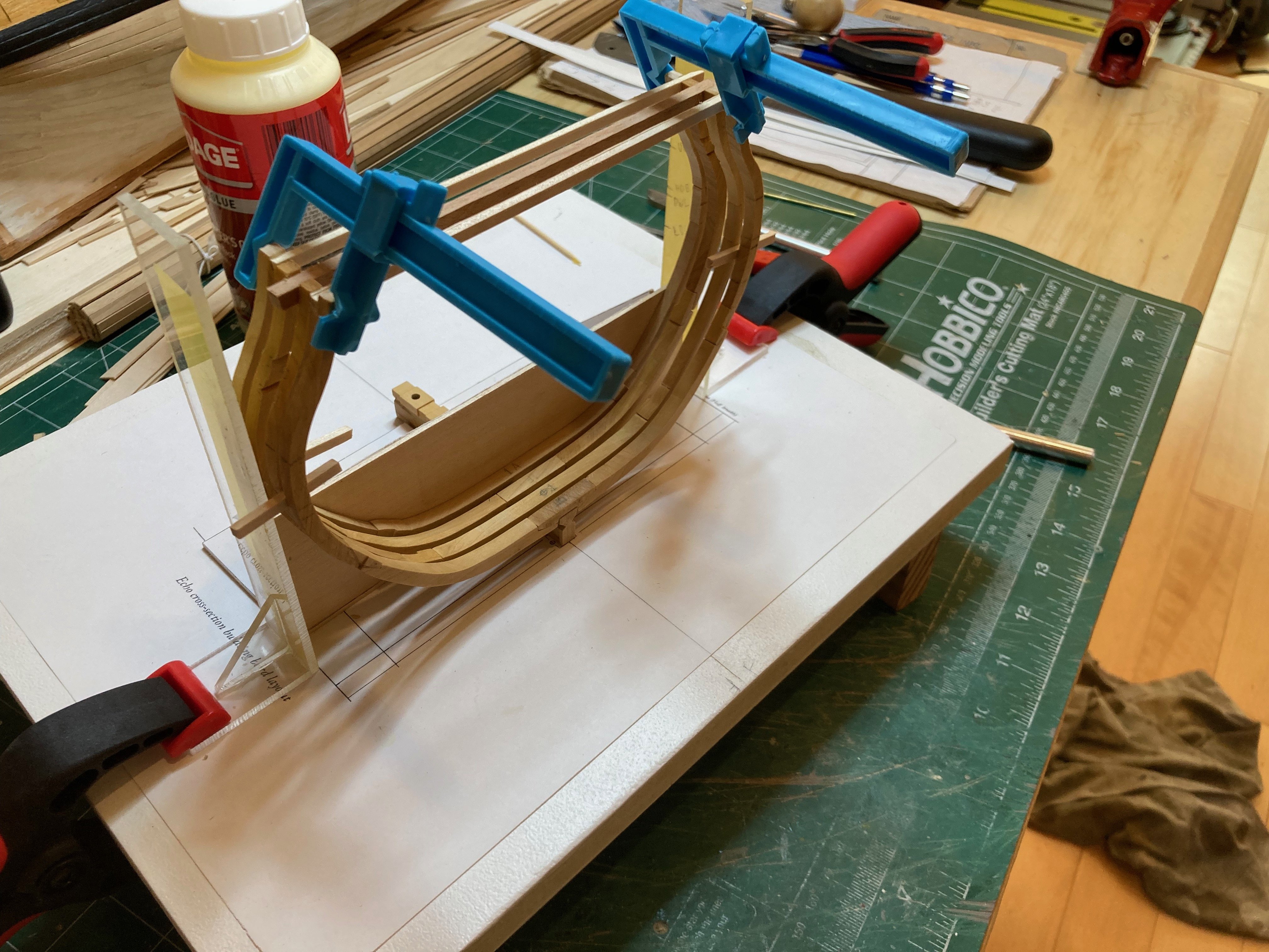
Got back home yesterday and used the east-west jet lag to complete and mount frame 1F in the peace of the early morning - a great time to be out in the workshop with a hot coffee. I dry fit the frame in place and used a small length of 1mm x 4mm walnut from the Bellona build to mark off the height of the sweep port sills in line with the aft deadflat frame. Checking these against the marks transferred from the sheer plan onto the body plan showed that the measures were spot on. I used a couple of triangular needle files to refine the notches and then mounted the frame. I had already attached a batten between the toptimbers of the aft deadflat frame - this was dimensioned according to the wider gap between DA and 1F that accommodates the sweep port, while I used a 2mm thick piece of scrap wood between the floor of DA and the cross-chock/first futtocks of 1F - this helped maintain the slight (approx. 2mm) lean aft of the second futtocks of 1F. The floor/futtocks of frame 1 aft are cut and need a bit of refinement, and I need to make the chocks for them as well, but since I just finished my 1 major home improvement task of the summer (a new fence around our front yard) and since the Admiral has been too pre-occupied with her business lately to invent other tasks for me, I hope to have 1A mounted on the keel by mid-week. It is a simple frame with no cast or shifted timbers and no need to notch out for ports or scuppers, so it will be considerably more straightforward than 1F was. Happy modelling and enjoy the photos! If the first photo makes the frames look like they're sitting a little squiffy, blame this on the unsteady hand of the photographer not the attentiveness of the modeller - though in this case they are the same person... hamilton


-
A beautiful rendition, John! Your display room is quite a treat to look at, too! hamilton
- 282 replies
-
- 3
-

-

-
- Bluenose
- Model Shipways
- (and 1 more)
-
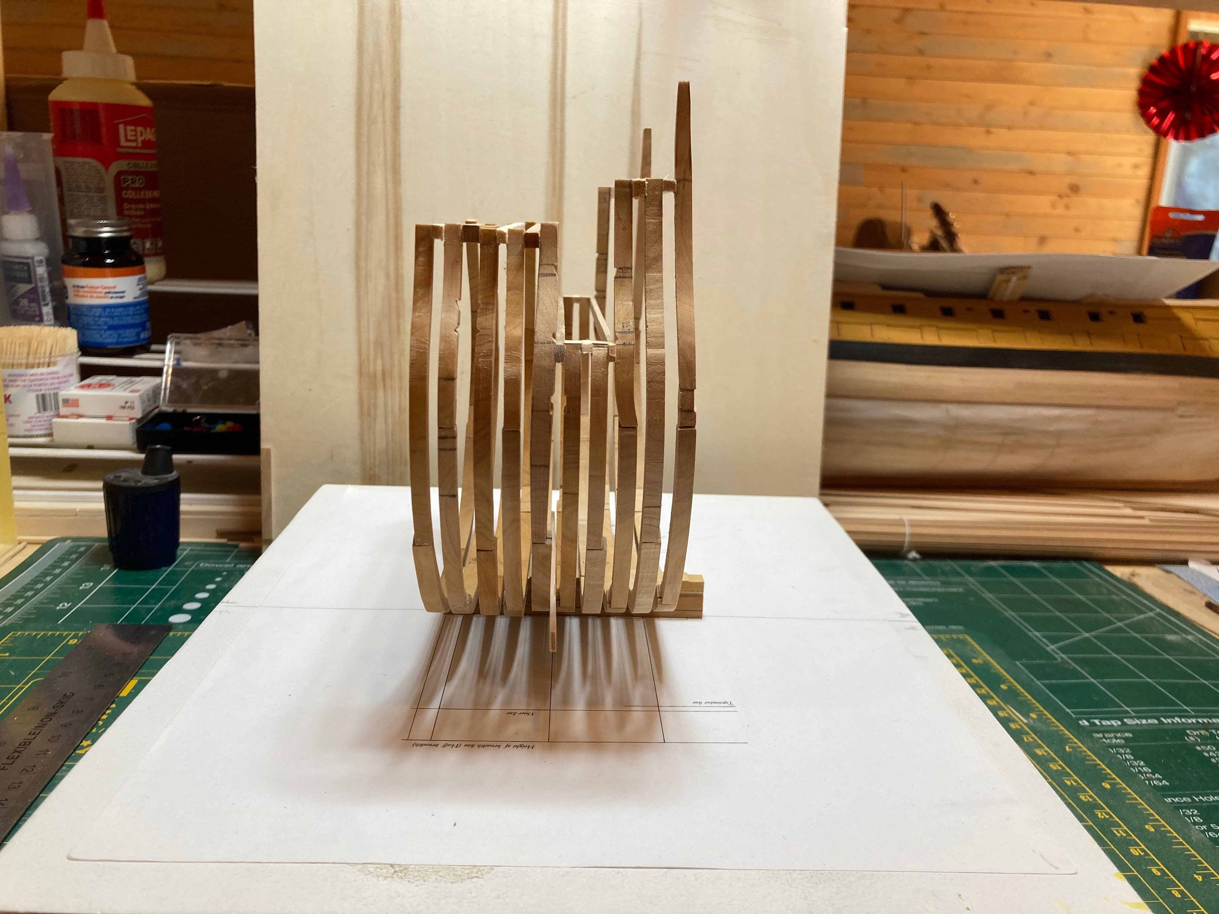
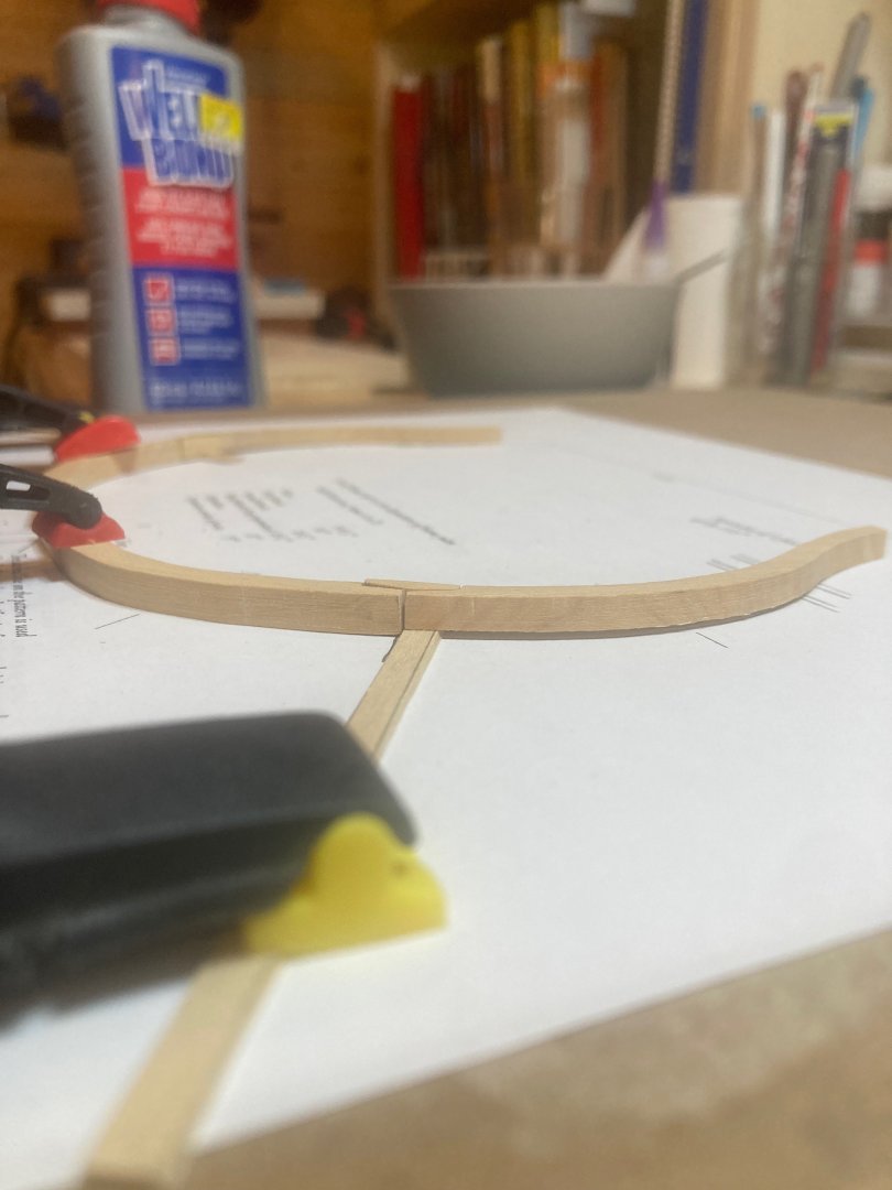
I finally got frame 1F right, I think - after constructing, deconstructing and reconstructing it 3 times! It has not yet been fixed to the keel, as there is still a bit more work to do - cutting notches for the sweep port sills. To mark these out, I transferred markings for the sills from the sheer plan (which shows their heights) to the frame drawing (which doesn't). This allows me to take an initial location from the plans, which can then be confirmed/corrected by setting up the frame on the keel and using a tick strip to ensure consistency with the notched face of the aft deadflat frame. I have now marked, but not notched out, these elements - the last before instaklling the frame permanently on the keel. I'm out of town and away from the workshop at the moment, so this will have to wait - but the elements of frame 1 aft are now laid out on the building board waiting for me to come home and once that's done I will mount both frames of the set at the same time. Frame 1 aft has the merit of not having any fiddly elements to it - no shifted or cast futtocks and no gunports or sweep ports to account for - so it's just a matter of refining the futtocks and chocks, assembling and mounting it. Here are some photos - enjoy and happy modelling hamilton


-
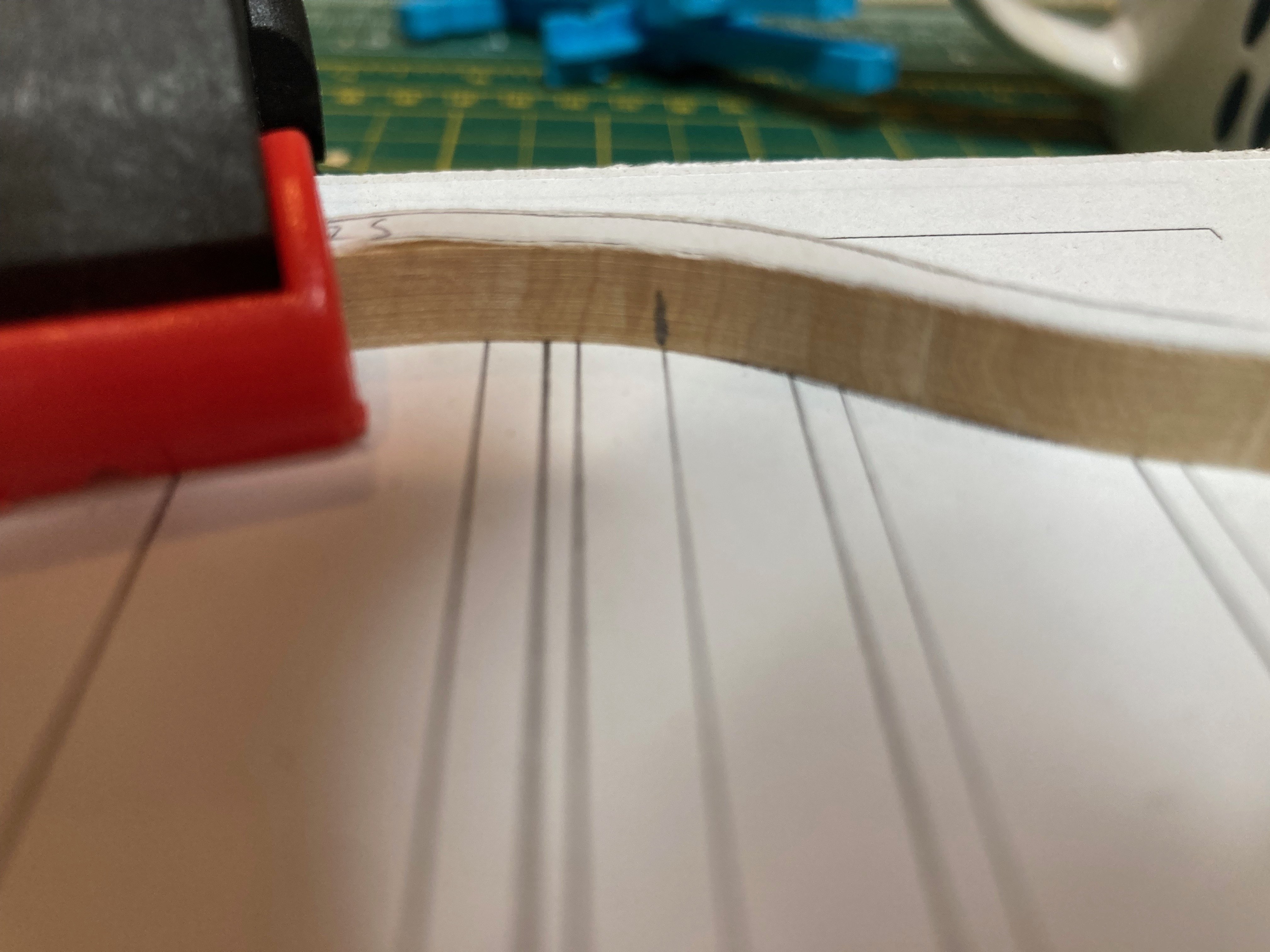
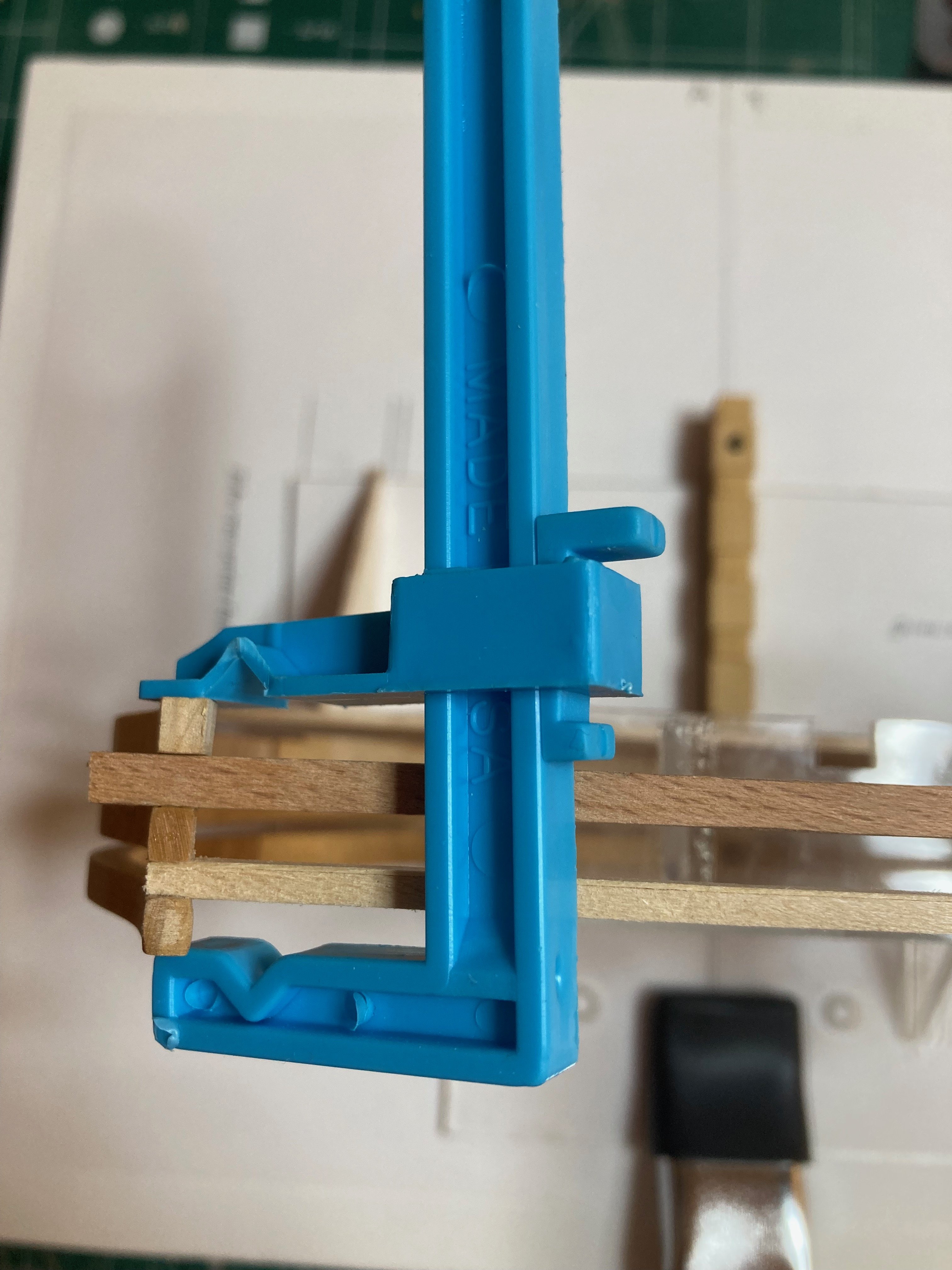
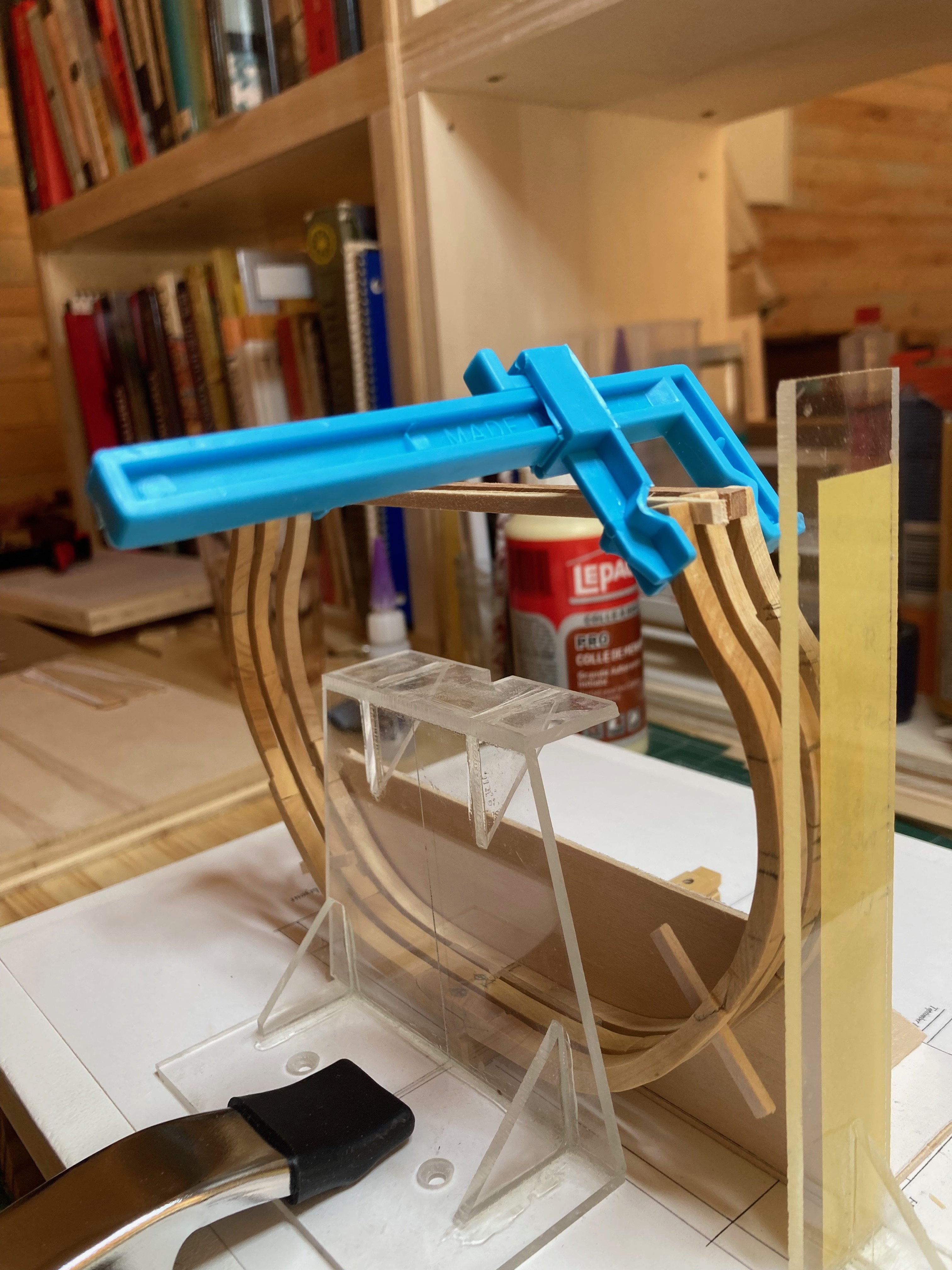
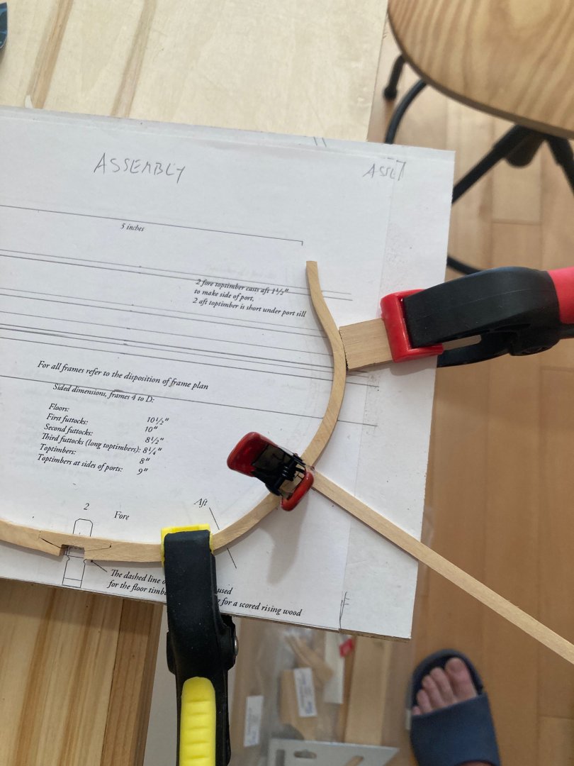
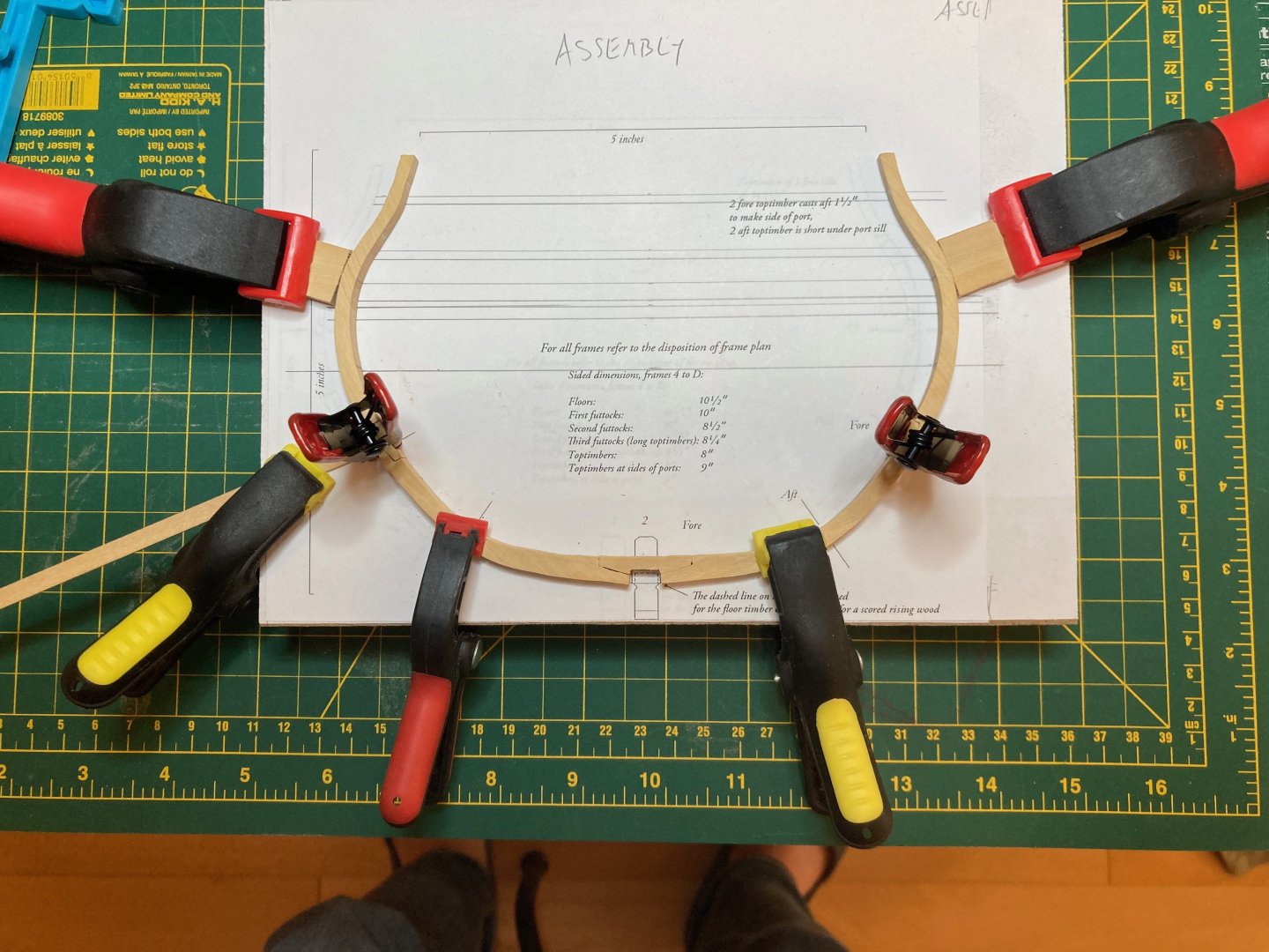
Wow - so I guess time has gotten away with me a little here....though with good excuse - was teaching a summer course and this occupied quite a bit of time through May/June and then once that was done, I spent some time on the house and garden - felling and disposing of an old cypress tree and constructing a new fence around our front yard. With these "serious" tasks out of the way, I spent a bit of time continuing with the second layer of lower hull planking on my Bellona, which is progressing quite slowly, since this is a part of ship modelling that I do not really enjoy - perhaps because, though I understand it in principle, and have followed many procedures detailed by some pros both here and elsewhere, my results are never great and the planks seem to want to run in insane ways - I'm beginning to think that this is down to either over-fairing or under-fairing of the bulkhead frames and I can't figure out which...... But anyway, this is a different log, so I should save my planking woes for the Bellona pages....in any case, though I mentioned above that I hoped to finish frame set 1 at the end of May, these frames are still in process. I thought I had completed 1 forward, but then realised that I assembled it with the second futtocks turned the wrong way on the first futtocks. I thought I had corrected this, but it turned out I made exactly the same mistake when I was trying to "correct" it from the first time!! This time, I managed to get it right (at least orientation wise) and have glued up the elements of 1 forward, and am now just waiting for the glue to fully cure before finishing the frame up and installing it on the keel. The second futtock of frame 1F leans back slightly - about 1/32" at scale. To achieve this, I placed the frame on the assembly template with the notched chocks facing downwards. I then ran a small 1/32" thick batten along the line on the body drawing that marks the joint between the futtocks - this propped the joint-end of the futtock up while its top end rested on the drawing. The photos below show what I mean. In the second photo, you'll notice that the chock is standing proud of the frame at its lower end - this will be corrected once the glue is fully cured. I'm going to be heading back east next week to visit my folks, so will once again be away from the bench, but if I can carrve out some more time today and tomorrow I can hopefully finish up 1F at least - the components of frame 1 aft are cut and need a bit more refinement before assembly and it's unlikely I'll be able to get to it before I get back home. In any case, enjoy the photos, basic as they are, and happy modelling hamilton

-
Well I see it's been a month and a half since I've updated here - blame my distractedness in picking up the Echo cross-section....Now that I've completed the first two frame sets on that build, more or less, and since my work is tapering off for the next several weeks, I will have a lot more time for modelling - between house projects of course (putting in a new fence, doing some tree maintenance and following the Admiral around her constantly growing garden trying to keep up with all the tasks she throws at me).... Today I took a couple of hours and started band "A" of the lower hull planking on the port side - starboard is nearly complete except for a couple of finishing planks at the bow. I don't have photos, unfortunately, but they look pretty much exactly like the ones from the last post, so I'll refer you back there - I'm going to push through the lower hull planking on Bellona over the next week or so before turning back again to Echo. Hope everyone's doing ok out there hamilton
-
British Pathe film: Model Boat Building, 1956.
hamilton replied to uss frolick's topic in Nautical/Naval History
Fancy ones, too, by the looks of it! hamilton -
Technically, it will be a "surprise", just not the one people might think... hamilton
-
British Pathe film: Model Boat Building, 1956.
hamilton replied to uss frolick's topic in Nautical/Naval History
I had a colleague once who decided to build a boat in his back yard. Problem was, once it was done he realised there was no room to actually get it out, so he had to rent a crane to lift it over his house and onto the street! Maybe the modeller featured in the image above built a scale crane to help him with those monsters! hamilton -
Hello Gaz Great start on the Peregrine. I believe this kit was released at around the same time as the Corel Greyhound and Eagle kits. My experience with the Greyhound was that it was a very challenging model with a great number of flaws in the design. But from what I see here these same problems don't seem to be at issue with the Peregrine! You'll find that there are few kits that have pre-cut rabbets - this is something that you either have to cut in yourself or that is created by narrowing the false keel and attaching separate keel, sternpost and stem parts. Corel's practice seems to be to provide a centre keel piece that includes the keel, so the bearding and rabbet lines must be traced from the plans and the rabbet joint carved out - this can be challenging on the smaller scale kits and especially since the ply used by Corel is not of the best quality - more like pressboard with thin veneers on either side. But you are doing a great job with these elements and it'll be nice to see the model shaping up. hamilton