HOLIDAY DONATION DRIVE - SUPPORT MSW - DO YOUR PART TO KEEP THIS GREAT FORUM GOING! (Only 20 donations so far - C'mon guys!)
×


shipmodel
-
Posts
941 -
Joined
-
Last visited
Content Type
Profiles
Forums
Gallery
Events
Everything posted by shipmodel
-
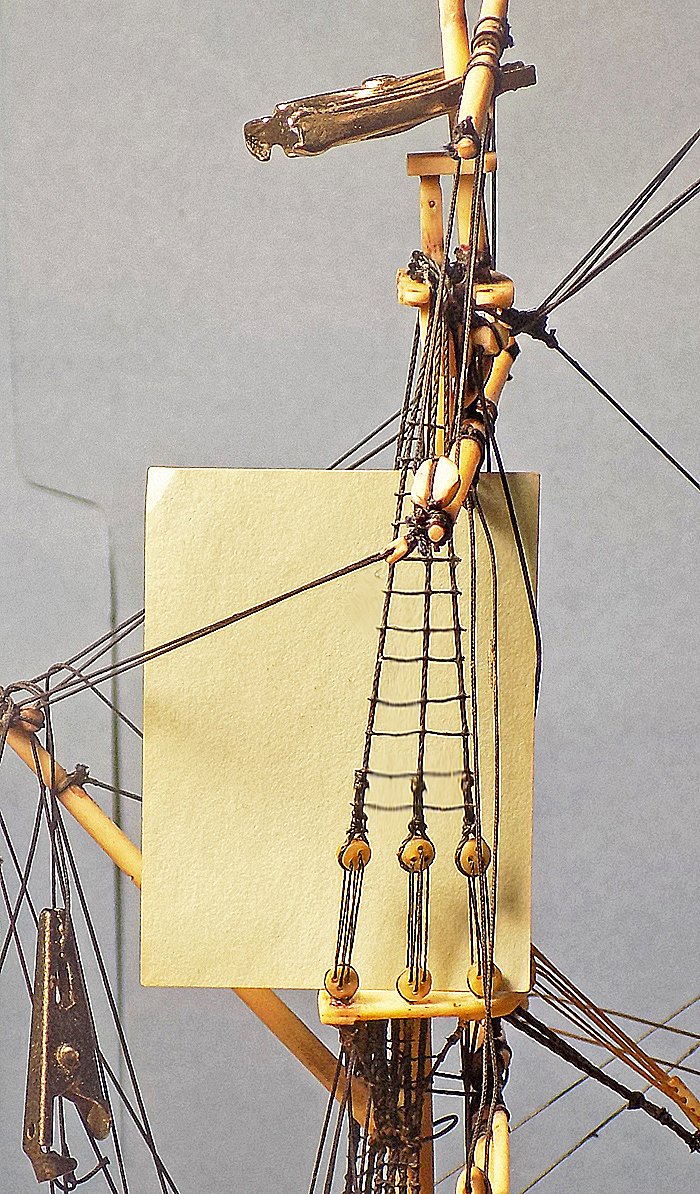
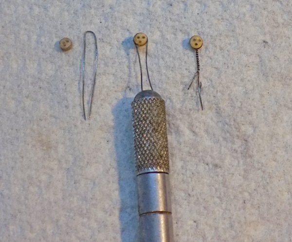
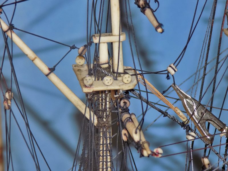
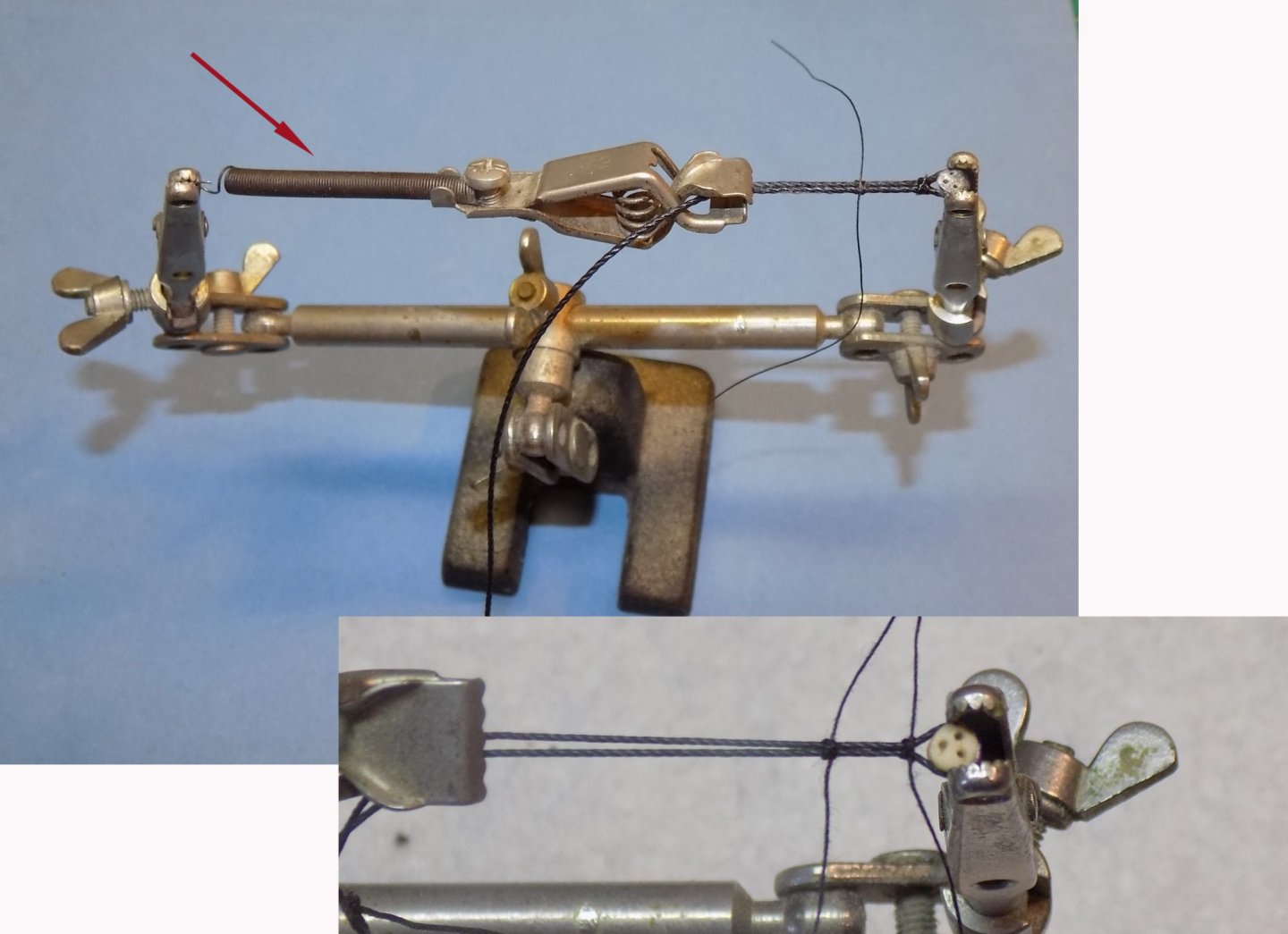
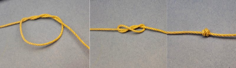
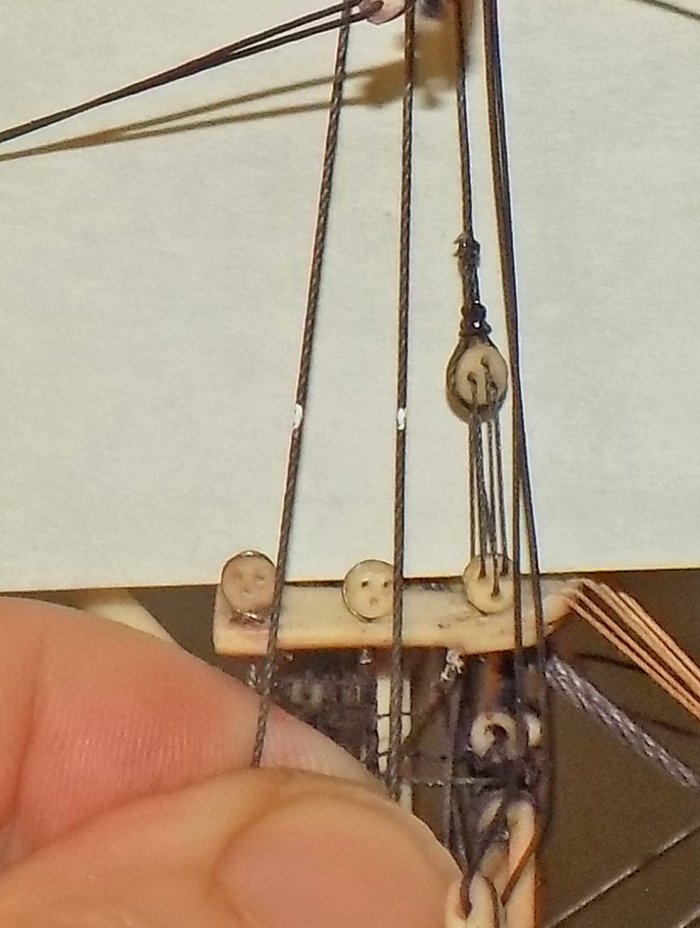
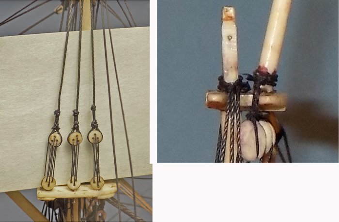
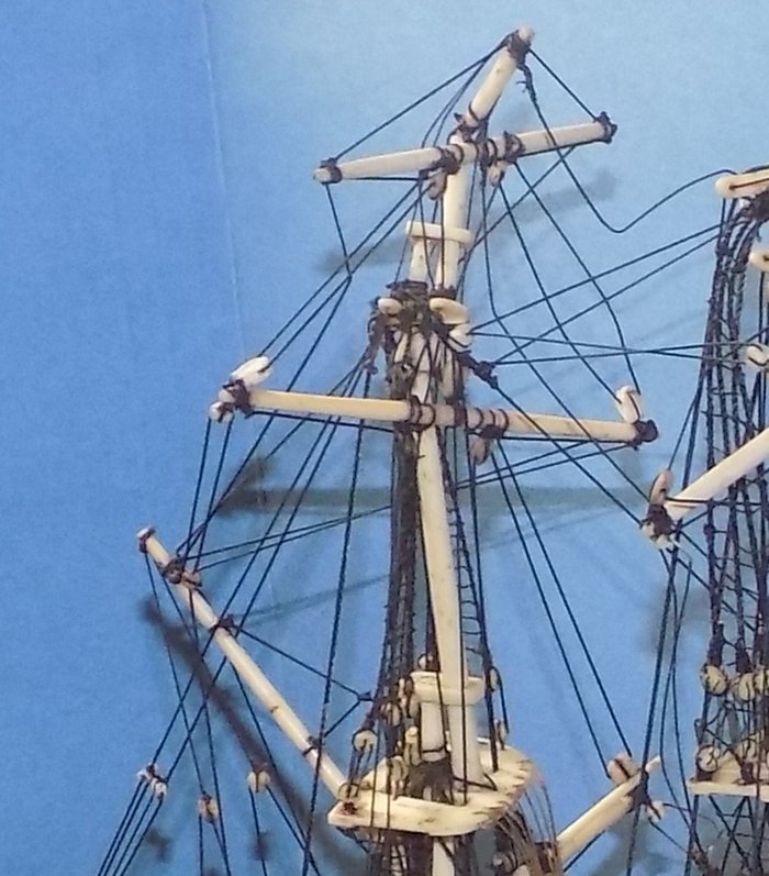
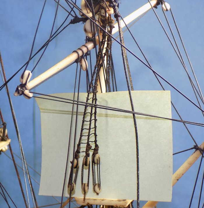
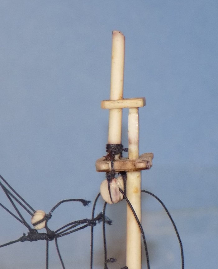
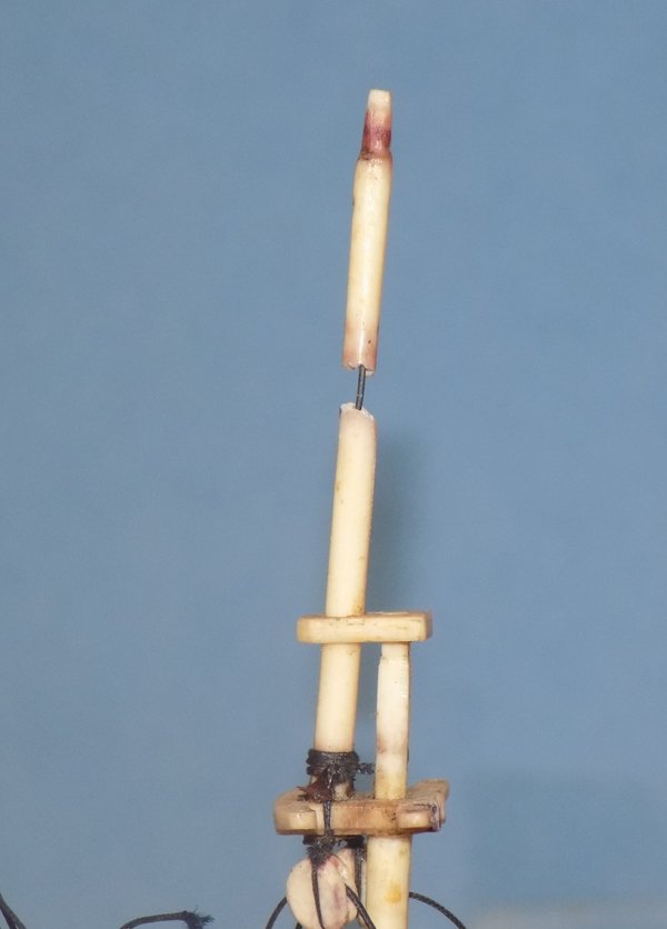
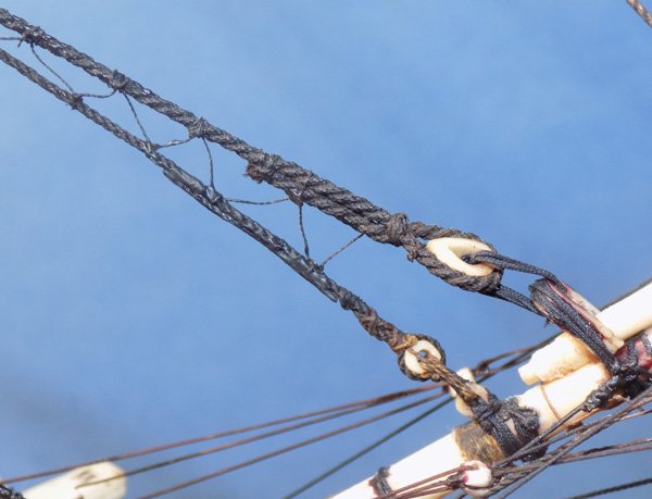
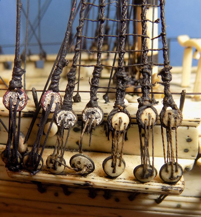
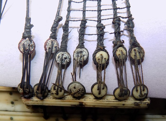
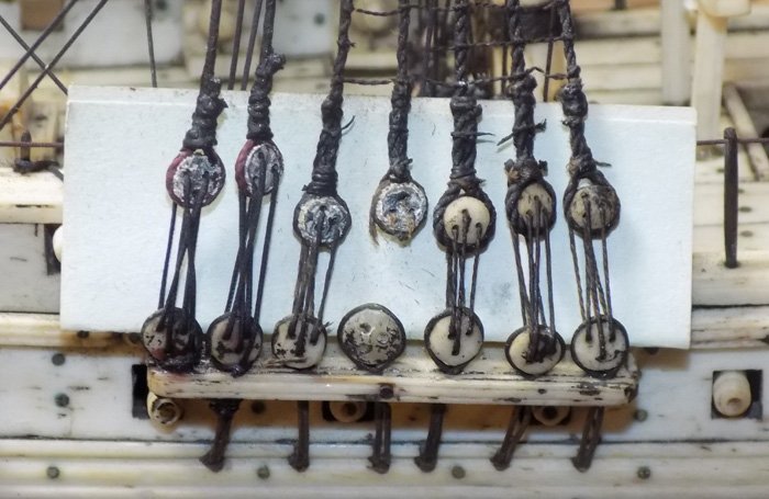
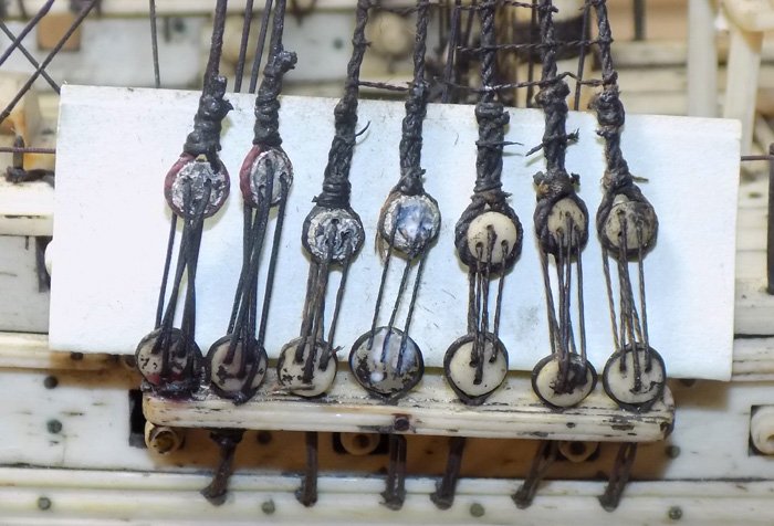
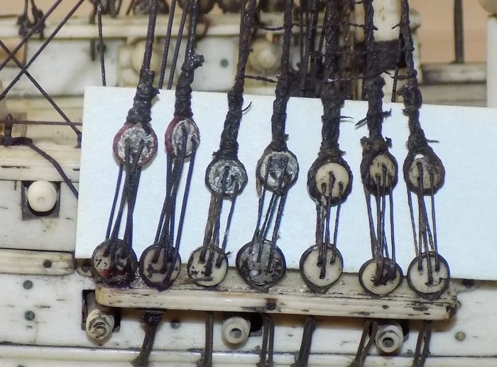
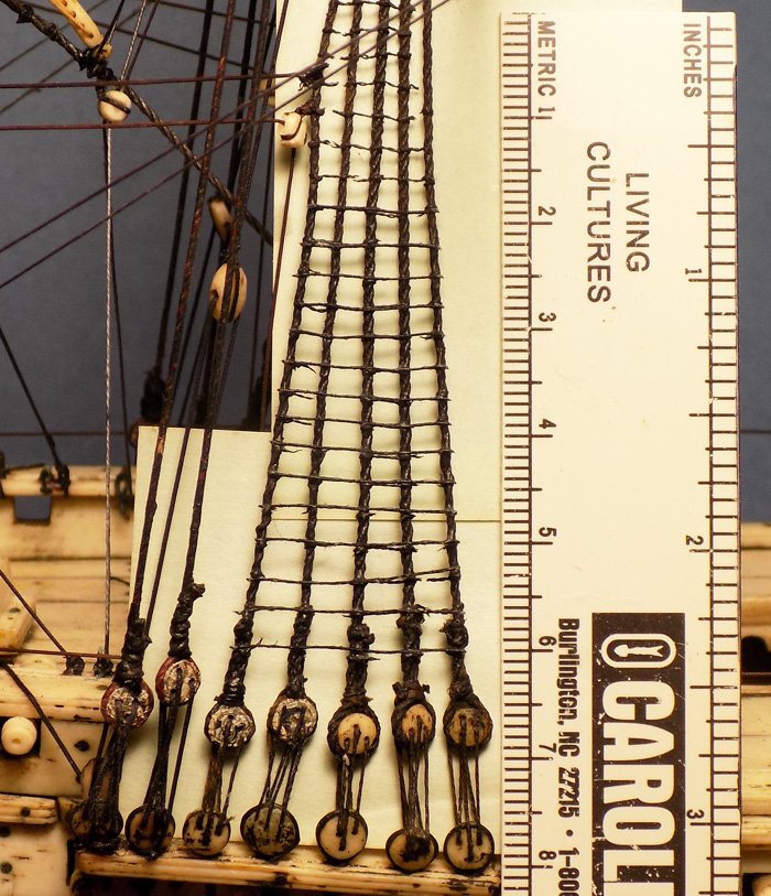
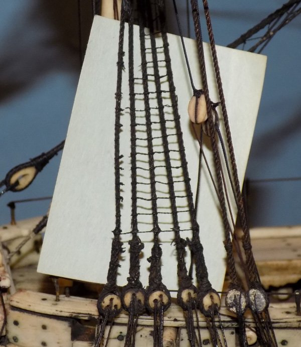
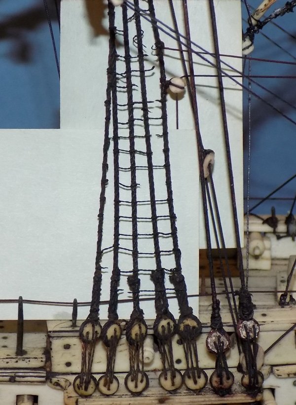
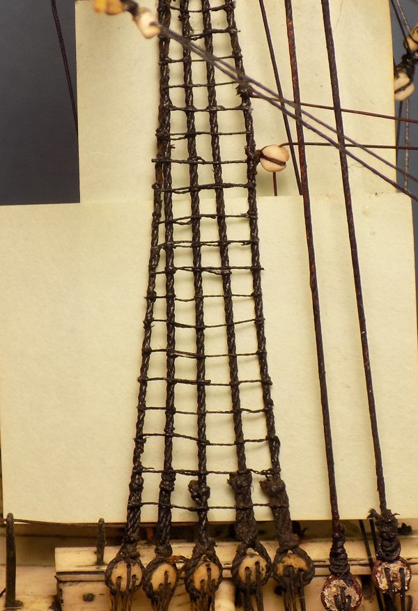
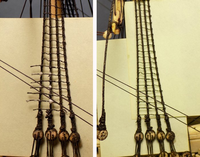
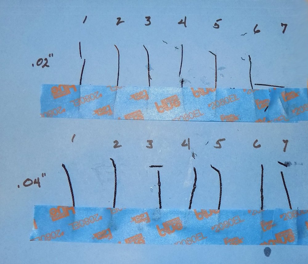
 Hi again – Thanks to everyone who hit the like button. The encouragement is very welcome, as always. The final bit of repair of the mast was to use a sander to make some ivory dust. This was mixed with PVA to make a filler that was applied to the join in the t'gallant mast.and sanded smooth to hide the break. With the structure of the mizzen mast fully repaired it was time to start re-rigging it. I lifted the t’gallant yard and clipped it to the mast to get some idea of where the cut and tangled lines would go, and what I needed to do. The first step was to replace the lower deadeyes for the topmast shrouds. In the usual course they would be stropped with rope which would be led through holes in the top to become the futtock shrouds and would then be tied to the lower shrouds. But here the futtock shrouds were already in place, although they were quite fragile. I therefore had to rig the deadeyes to the top only and in such a way that they could withstand the stresses of the shrouds. My solution was to rig them with metal strops with twisted stems. I made them by folding a length of soft iron wire around a deadeye then clamping the ends of the wire in the slot of a knife handle. Spinning the handle while holding the deadeye steady secured the deadeye in the strop and created a neatly twisted stem. If you do this be careful not to overtighten the strop because you can split the deadeye or block that you are working on. (Been there, done that, got the apron . . .) The stem was clipped off leaving a shaft a bit longer than the thickness of the top. This was secured through the top with a drop of cyano which locked onto the twists of the shaft. Once all three on a side were installed the extra lengths of the shafts were trimmed off. In the photo you can also see one of the several small clips from the electronics store which hold the loose ends of the lines that I detached until they can be retied. Preparing to rig the shrouds themselves I found that the mast cap was completely loose. It could be raised on the t’gallant mast to open up the doubling so the heads of the shrouds could be more easily rigged. The t’gallant mast was also loose. This could have been intentional or a result of the old glue drying out. In any event it made the rigging just a little easier. The shrouds themselves began by turning in an upper deadeye into 0.020” dyed line. To do this I used my medium-tech stropping jig. It consists simply of a Helping Hands type tool with the addition of a light duty spring (red arrow) and an attached flat-nosed clip. In use the fitting to be stropped is held in the right hand vertical alligator clip and the stropping line taken around it and trapped in the larger clip. The line is placed under light tension that straightens the line and stabilizes it so it can be worked on easily. To match the other shrouds on the model two small round seizings have been tied around the shroud lines about ¼” apart. They were secured with PVA and when the glue dried the excess seizing lines were clipped off, as was the extra shroud line. This method makes stropping deadeyes, blocks, hearts, etc. very easy, regardless of how small the fittings and the lines are, since the line is held under tension at all times. The resulting stropping is neat and tidy and repeatable. Also, since the deadeye is not glued in it can be rotated in the strop even after the seizings have been tied. You can put on three seizings if you want. You can even make the crossover throat seizing if you flip the deadeye over in the alligator clip while holding the shroud lines stationary, then lace the seizing vertically rather than horizontally. In any event the upper and lower deadeyes were laced together with lanyards of 0.07” linen. To lace the lanyards I start by tying a stopper knot that cannot be pulled through the initial hole in the upper deadeye. I have been asked about this before and, though it is a bit of an aside here and most of you already know the technique, here is my simple method. To make it clearer, I photographed some cable that I spun up rather than the thin black line that was actually used, but the process is the same. I first make a double overhand loop by taking the running end of the line around itself twice, leading to the look of the knot on the left. As the two ends are pulled away from each other the knot deforms into the figure-8 shape in the middle. Continued pulling results in a tight stopper knot which, like a clove hitch, has the line entering and leaving the knot in a straight line. It only gets tighter with added strain. It takes only a few seconds to tie the knot this way and clip off any unwanted extra line. With the forward deadeye on the starboard side rigged the line was taken up and around the masthead to the port side where another deadeye was turned into the end of the line and laced to its lower deadeye. The remaining shrouds on each side had a loop seized in the top and placed over the masthead. To get the proper heights for the remaining deadeyes the shrouds were held against the lower deadeyes and small dots of white paint indicated where the bottoms of the upper deadeyes had to go. The deadeyes were turned in on the stropping jig using the white dots as guides, The white paint was hidden with a drop of black paint, then the lanyards were laced for each one. The resulting rigged deadeyes look neat and level at the bottom and at the masthead they look clean and trim. The ratlines were made of more thin linen line which was glued across the face of the shroud gang. I tried tying clove hitches, but the remaining lifts and braces from the spars got in the way and made this nearly impossible. The result was good, and without the paper backing for contrast it is difficult to tell any difference. Next, finally, I will complete the rigging repairs. Till then, stay safe. Dan
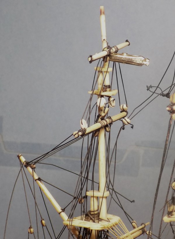

- 95 replies
-
- 24
-

-

-
- POW
- Bone model
- (and 2 more)
-
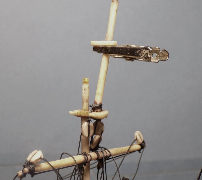
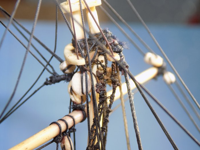
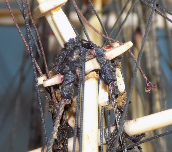
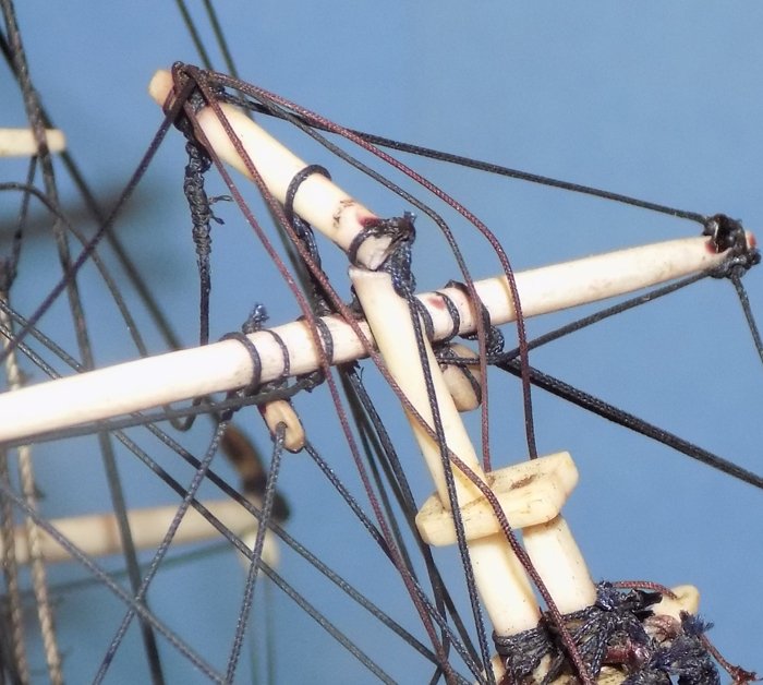
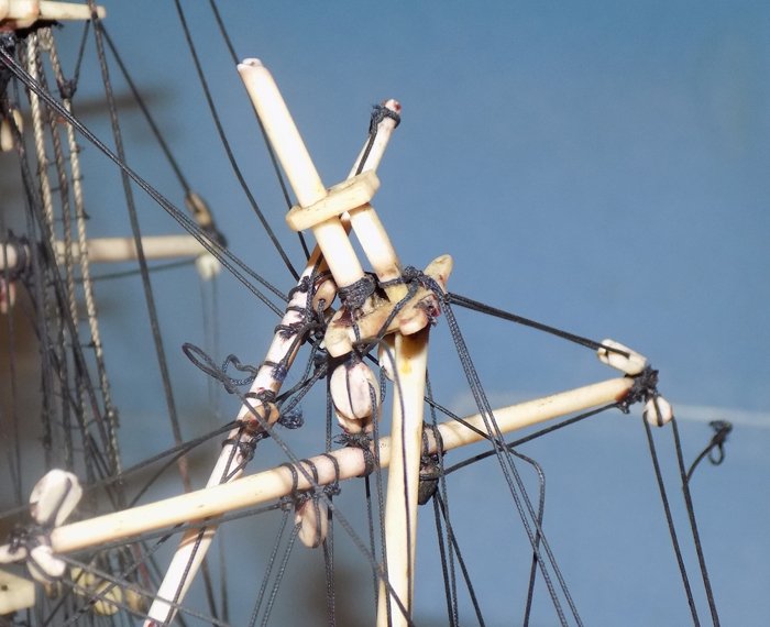
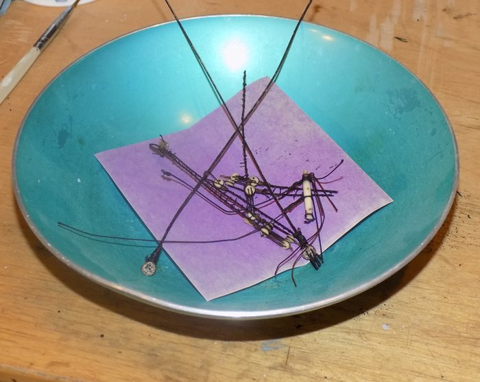
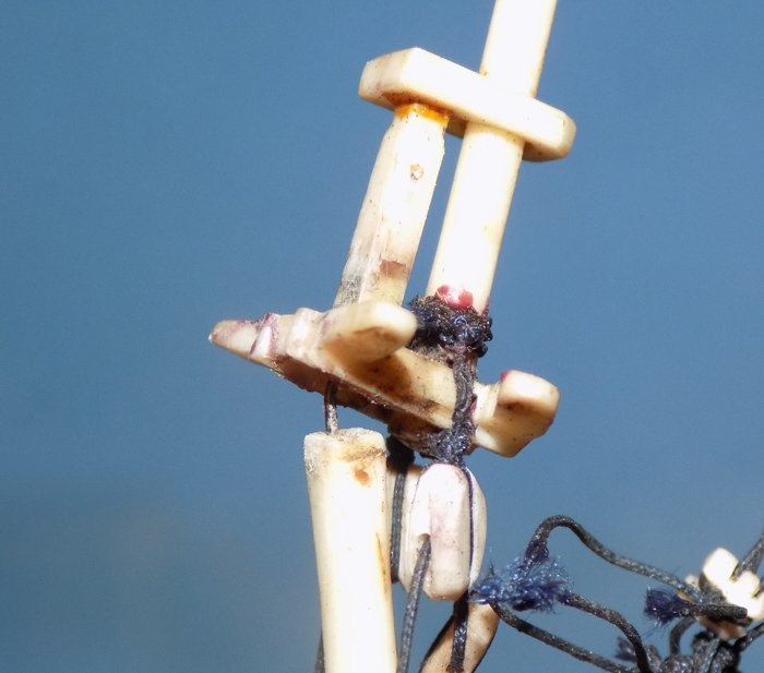
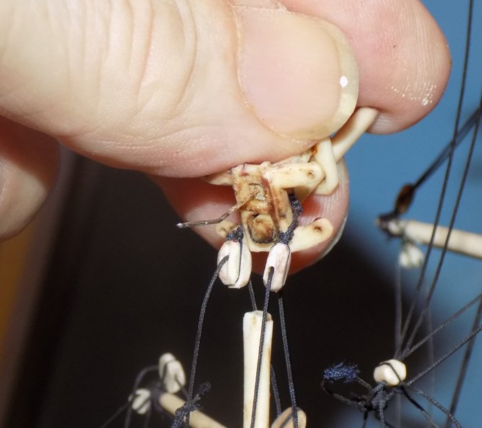
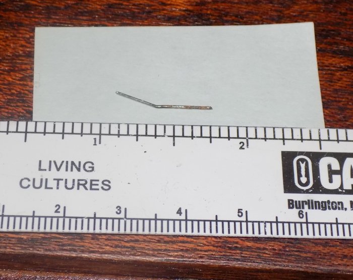
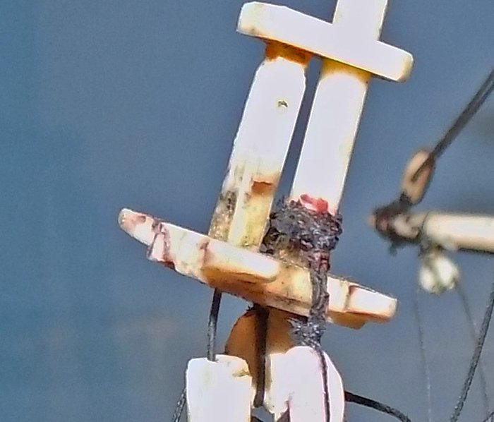
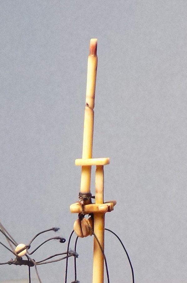
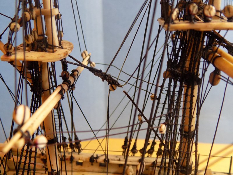
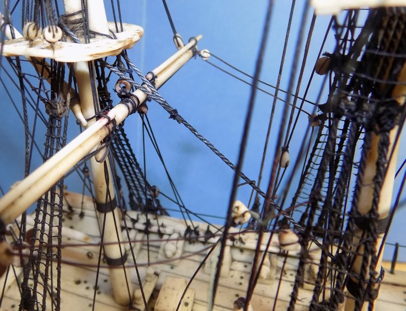
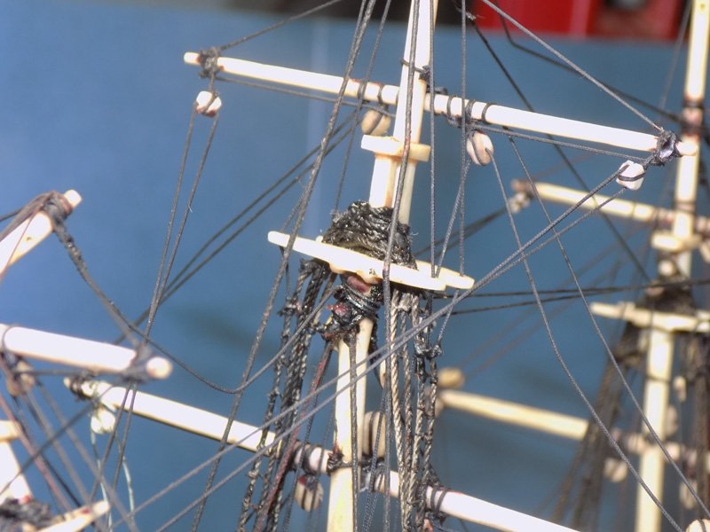
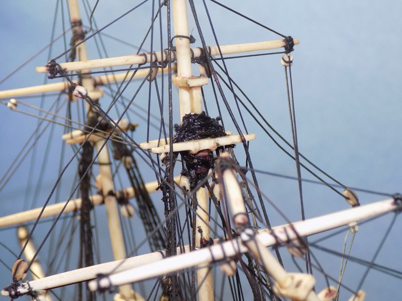
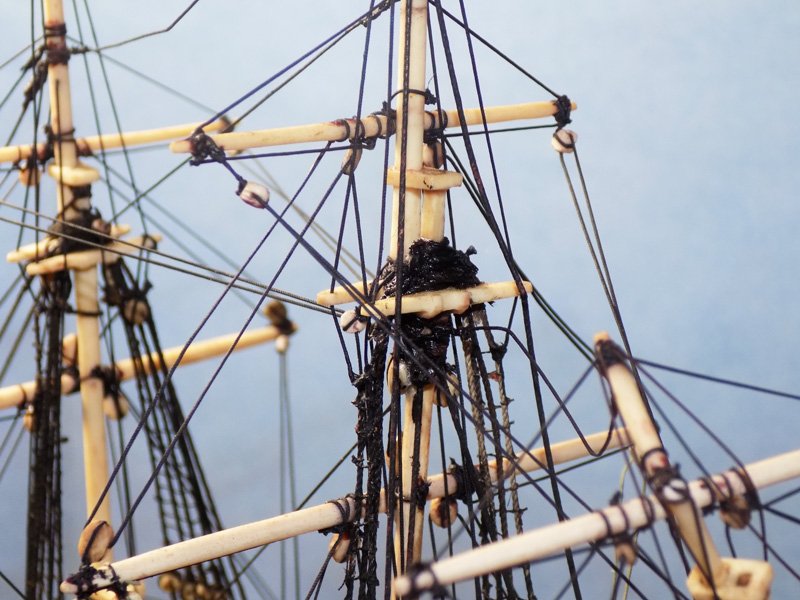
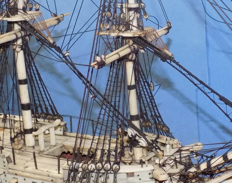
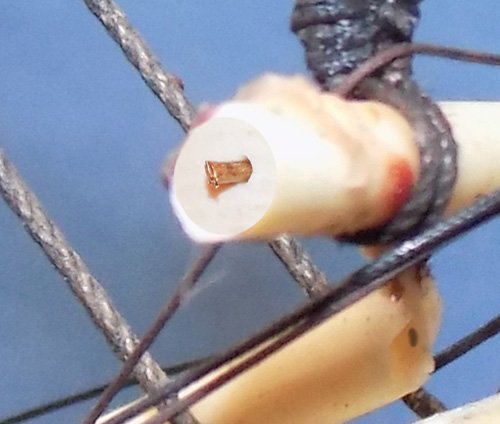
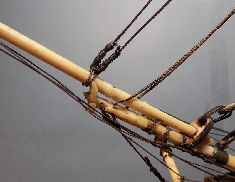
Hello and, as always, many thanks for looking in. Druxey, Keith – nice names. I like “Boneapart.” It sounds appropriate for a French ship that has suffered at the hands of the perfidious Albions, or at least their American cousins. Time to put the bones back together. Here is how she was received. A break at the mizzen masthead and another break in the middle of the mizzen t’gallant mast. The stresses of whatever caused the breaks pulled out two of the topmast deadeyes on the starboard side, as seen in the prior photo, and all three on the port side. In theory I could have pulled down the deadeyes and secured them back in their holes in the top, then redid the ratlines as I did on the lower shrouds. However, the rats’ nest of overlapping and glued lines at the masthead was such a mess that I did not think such a simple solution would work. Seen from the rear the various different thicknesses, colors, and even the seizing techniques of the many lines is evident. Also clearly seen is the same mortice and tenon joint between the round body of the mizzen mast and the square masthead. The break in the t’gallant mast was clean, but angled. It happened at the hole through the mast that was originally meant to represent the mast sheave for the t’gallant yard. But in closeup it is clear that the prior restorer had run the halyard from the yard up and around the mast, then a second line was tied to this first one and taken down to the deck. It would have looked OK in a ‘fool the eye’ sort of way, if you don’t look too close. I tried a simple repositioning of the topmast, as I had for the main mast. No matter how much I moved it around, and as hard as I tried to straighten it up, it would never go back to vertical. I would have to strip off some of the rigging to release the stresses, then reposition the masthead. One by one, starting from the top and working down, I removed each line and tried to straighten up the masthead. The first to go were all the lines leading to the broken tip of the t’gallant mast, as well as the piece of mast itself. Cutting the halyard, sling, and lifts released the t'gallant yard which was laid forward on the main t'gallant braces that were tied to the mizzen topmast stay. Working down, the topmast backstays were removed. Then the topmast shrouds, then the topping lift lines for the mizzen driver gaff were released, etc, etc. Ultimately I had a small bowl of detached lines and ivory fittings, with other lines detached from around the mast and laid back on themselves. This continued until the only lines left on the masthead were the strops for the topmast jeer blocks. The jeer lines themselves were released from the belaying points at the deck so the masthead could be lifted. Doing so revealed that there was a metal pin between the mast and the masthead running through the joint. Loosening the jeer lines even more I could lift the masthead up high enough to completely release it from the mast. Now I understood why I could never get the masthead back in place. The pin was made of hardened steel which took a bend when the mast was broken. The amount of force needed to straighten it out in situ would surely have cracked the mast. Instead, I replaced it with a similarly sized length of annealed iron wire. Now, if there is ever another break, I expect the pin to bend before the ivory cracks and the future restorer can bend it back into position. The masthead was replaced in position and secured with a drop of cyano in the mortice joint. Next I drilled about ¼” into each side of the t’gallant mast break and pinned across the break with another length of iron wire. The pieces were fit together and secured with cyano. Next I will start re-rigging the mast. Till then, stay safe. Dan
- 95 replies
-
- 19
-
-
- POW
- Bone model
- (and 2 more)
-
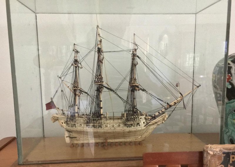
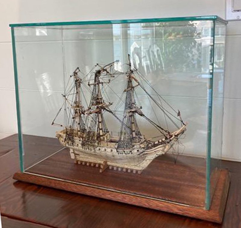
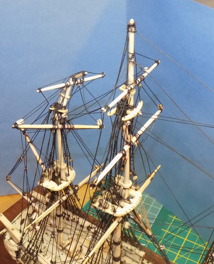
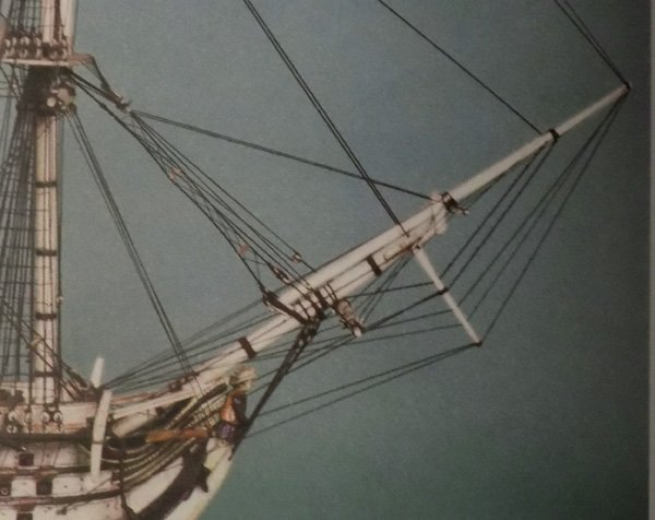
Hi again to all, and thanks for the likes and compliments – Druxey - Good idea. I have broaches somewhere, but the glue was pretty hard. I'll bring them out next time if I need them. 74_boni - I hope that these build logs will help preserve my experiences and techniques. I have converted a few into articles in the NRJ and will do so again when I collect the time and mental energy. As for the model - My client just got back to the States and located a photo of what the model looked like after the 1953 restoration and before the current accident. It is the middle one below. So now we have three recorded moments in the life of this hard-luck model. I will post the fourth when my own repairs are completed. Dan
- 95 replies
-
- 13
-
-
- POW
- Bone model
- (and 2 more)
-
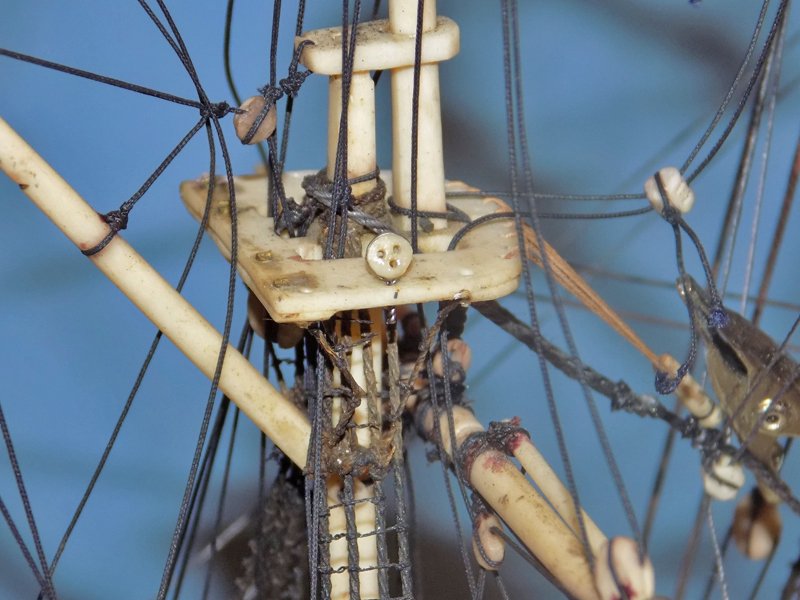
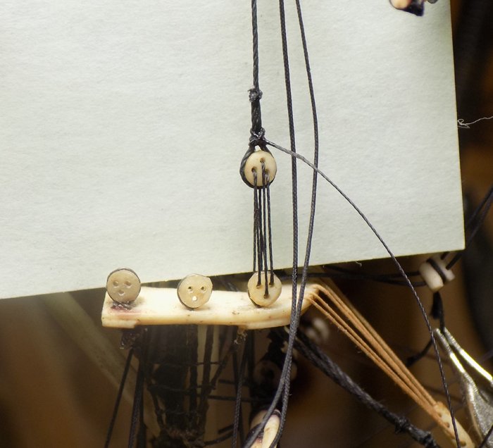
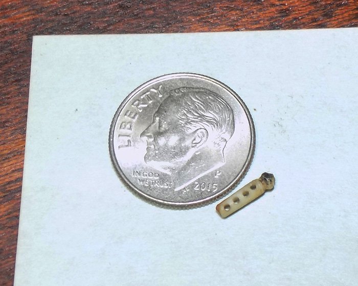
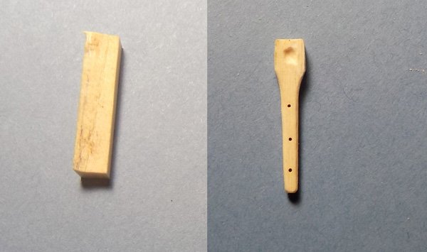
Hi again to all – Thanks, as always, for the likes and comments. Now that the mizzen stay was rigged I turned to rigging the crowsfoot. The euphroe was included in a small envelope of loose parts that the client sent me. Here it is, and you can see how small and delicate the original POWs made it. Next I had to clean out the holes in the edge of the mizzen top. This was the hardest part of this repair. Using a piece of thin brass rod bent into an “L” I cleaned out four of the eight holes. The last four were clogged with dried glue or finish of some kind. For these I had to drill them out. I first tried a hand held pin vise, but I could not deliver enough pressure for the bitt to catch and drill. Reluctantly, and with great care, I turned to my cordless Dremel. Without turning it on I angled it between the other rigging lines and set it on each hole location. Then I turned it on and gently drilled through. I turned it off before pulling it out. The worst thing I could imagine would have been to catch a rigging line in the spinning chuck. The damage that would have done would have been catastrophic. With the holes cleared I took a length of 0,015” linen line and dyed it tan. I tied a stopper knot on one end and stiffened the other end with cyano, forming an integral needle. Then it was a simple matter to lace the crowsfoot back and forth between the top and the euphroe, ending with a final knot under the top. Once the crowsfoot was rigged I retied the double block for the main topmast braces to the stay. Finally I tied a long length of 0.010” dyed linen line to the stay, ran it up to the blocks on the ends of the spars, back to the double block, and then to empty belaying points on either side of the deck. Next I will have to address the double breaks of the upper mizzen mast. Till then, Stay safe. Dan

- 95 replies
-
- 14
-
-
- POW
- Bone model
- (and 2 more)
-
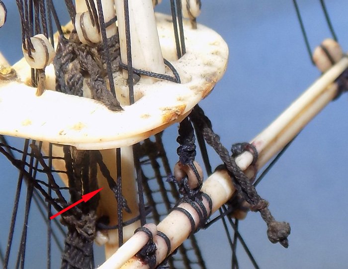
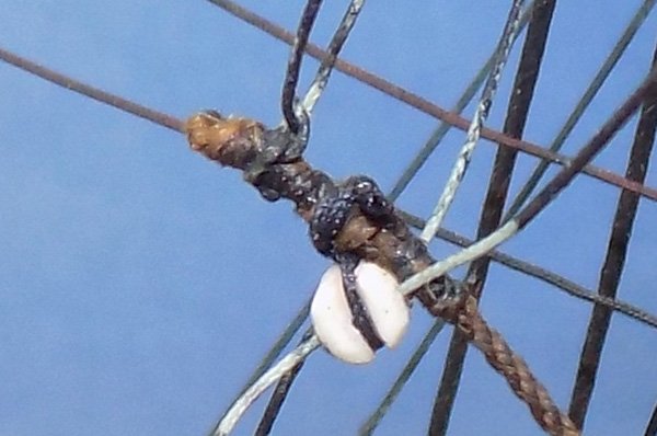
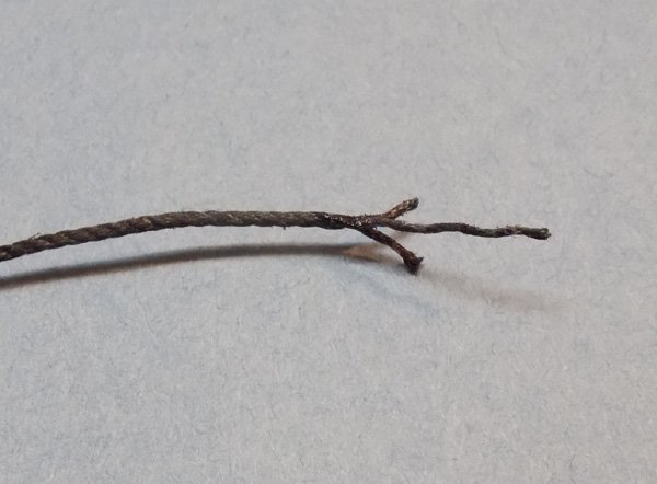
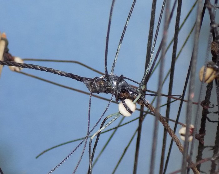
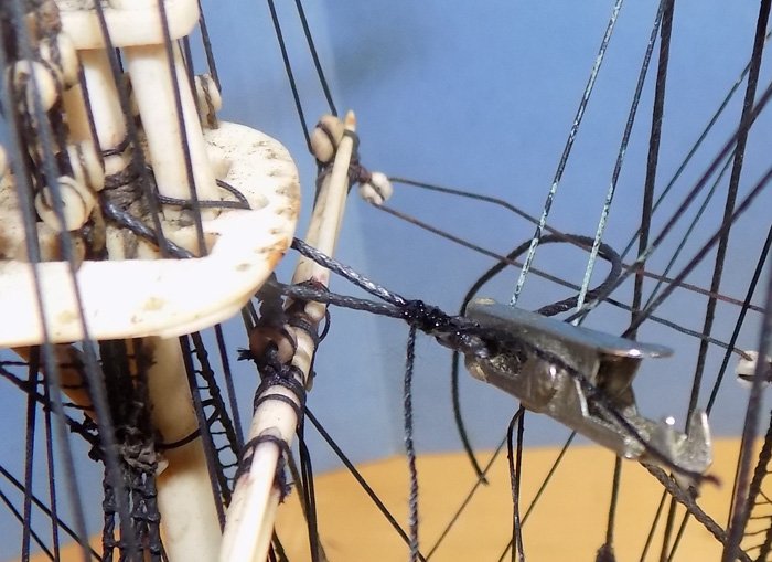
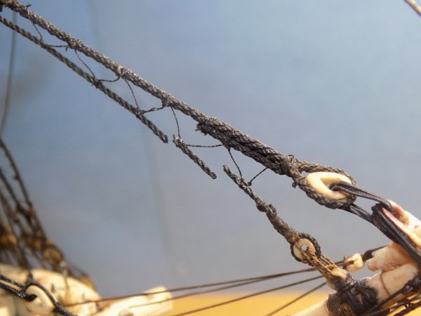
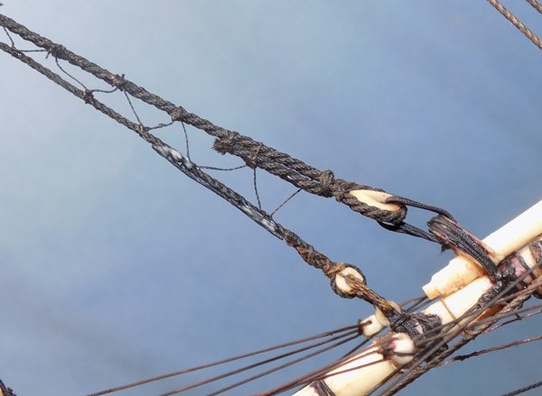
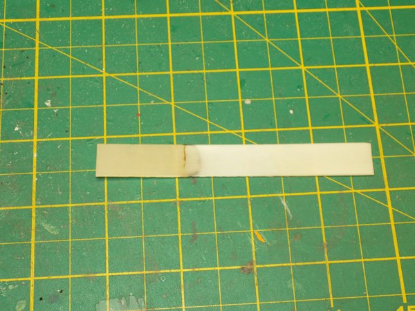
Druxey - I love the smell of burning bone in the morning. It smells like . . . like the dentist’s chair! Or like the Marathon Man “Is it safe?” scene, one of the truly nightmare moments in movie history. Meanwhile, back in the shipyard – With the mainmast fully upright and lines tensioned I continued aft to the broken mizzen stay. It was intact from where it was seized to the main mast up to just below where the mouse and eye would have been. It appeared to be original, so one priority was to preserve it if possible. At the upper end the loop around the masthead had broken on the starboard side just under the top. The red arrow identifies the broken end. There is a section missing, so it could not be salvaged. When I went to remove it, the line all but crumbled away. The crowsfoot was gone completely, though some shreds of line were still stuck in the holes in the edge of the top. The euphroe was also missing but later found in an envelope of separated parts. Examining the other side of the break under magnification confirmed that the stay was original. The brown tuft looks, to me, to be made of vegetable fibers, meaning linen rather than cotton. The lines and block that tie to it are part of the main topsail braces. They are tied to the stay, run to single blocks on the ends of the spar, back through this double block tied to the stay, and then to belaying pins at either side of the deck. From the changes in color around and through the block I’m sure that these are replacements. But since they are tied to the original stay, I decided not to change them, although I will paint them to hide the while sections. The puzzle here was figure a way to splice a replacement line to the remaining original stay. It had to be done end to end without creating too large a bulge. After looking at the end to be spliced I decided to try unlaying some line, leaving one long strand but cutting the other two short. This would give me a reasonable gluing surface area while minimizing bulk. First the lover section of the stay was given a coat of MC followed by a similar coat of thinned PVA. I knew that I would be putting some stresses on it and I wanted it as strong and flexible as I could. Then the mating surfaces were painted with PVA and lined up with each other. I held them in place by hand until the glue set up. Then I gently looped and tied two thin lines around the overlap. Tightening them clamped the splice and reduced the bulge. After glue dried the clamping lines were removed. Despite my best efforts I wasn’t completely happy with the size of the splice, but I could not see another solution that was any better. The next day I looped the new line around the masthead, clipped it back on itself and seized it together. I released the clip and cut off the excess line. It looked OK but was a little skewed so I moved to center it, at which point this happened! After some choice words I realized that this was a blessing, although in heavy disguise. I had lost a day’s work, but now I was forced to get rid of the unsightly bulge. I cut the topsail braces off and freed the double block for later use. Then it was a relatively simple matter to seize some appropriate line around the main mast, then take it up and around the mizzen masthead, seizing it together as before. The crowsfoot next. Dan
- 95 replies
-
- 17
-
-
- POW
- Bone model
- (and 2 more)
-
Marc and Mark - In our area, at least, the Future line has been discontinued. It is now known simply as Pledge Floor Care. Same stuff, same bottle, different label. Dan
- 2,696 replies
-
- 4
-
-
- heller
- soleil royal
- (and 9 more)
-
Beautiful work Marc. That's quite a set of 3-D jigsaw puzzles you have created for yourself. I'm really enjoying watching how you solve them. I agree with Michael. Maybe an overcoat of clear gloss would hide the blemish. I would thin out the liquid so it will flow into your fingerprints a bit more. Best of success. Dan
- 2,696 replies
-
- 2
-
-
- heller
- soleil royal
- (and 9 more)
-
Alan - in my experience, Druxey intends every one of the many puns he uses. He is a master of understated humor. Or was that humour. Bob - Pretty much the only bone on this model, and most other POW models that I have worked on, is the planking. Both the hull and decks are planked in thin bone veneers over a wooden core. I think that this may be because bone will soften by immersing it in vinegar and can be bent to the shapes needed for hull planking. I don't know if ivory will soften in the same way. Ivory is used for all the masts and spars. I think the grain in the bone (actually the holes from its blood supply) would weaken any long unsupported cylinders and make them prone to snapping. Ivory is also much easier to work with for making the blocks, guns, deck fittings and, of course, any and all decorative carvings. At the time, whaling was in full swing, so tooth ivory was plentiful, and I know that there was a lively trade in elephant ivory too, as the many Asian art objects show. I can imagine making an entirely bone model, but only if I figured out how to solidify it for the masts, etc. Perhaps an infusion of a stiffening liquid like the thinned epoxy that was suggested earlier might work. Best of success with your work on behalf of breed preservation. Dan
- 95 replies
-
- 7
-
-
- POW
- Bone model
- (and 2 more)
-
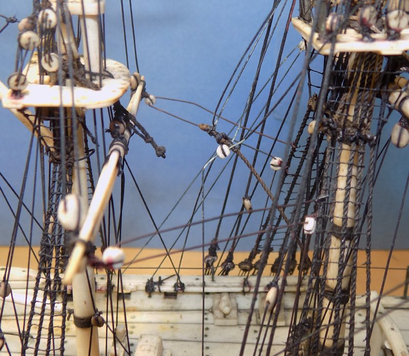
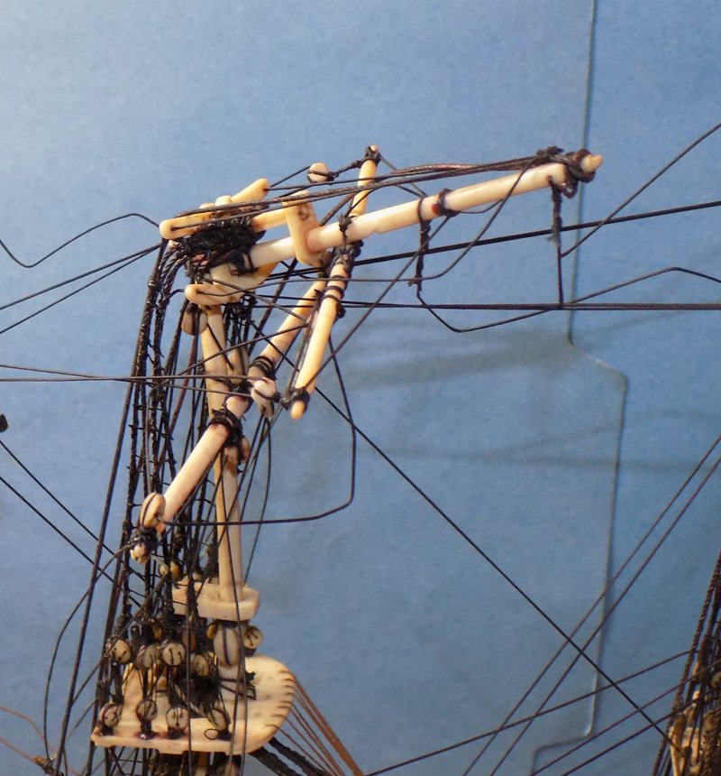
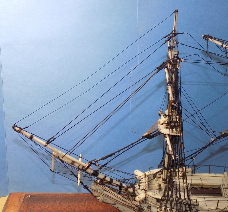
Hello again – Thanks for the likes and compliments. Barkeater - That’s exactly what it looks like to me too. It might not be that difficult to open the seizing around the bowsprit, run it above the pinrail, and reseize it again. My hesitation is because of the limited space in which to operate and whether any change in angle might damage the snaking lines. Hmmm This segment is short but important. I decided that it was time to tackle the broken mainmast. Here is how I received it, broken just under the trestletrees and the doubling of the head of the topmast and bent forward almost 90 degrees. The stays that led forward were kinked but not broken. The topmast shrouds and backstays were also intact, but bent sideways. Taking a closer look I realized that those shrouds were not original. They are the wrong color and lie over a mass of cutoff ropes that must have been the heads of the original shrouds. The good news was that this made them more flexible. More importantly, the mast was not broken. The head of the topmast was a separate piece from the body of the topmast. Possibly that was because that was where it changed from a round cross section to a square one. In any event, the mast was not splintered. The lower mast seemed to fit into a socket between the trestletrees, and there was the same red glue residue of an earlier repair. With that in mind I started to move the pieces around, as I had with the bowsprit. I found that I could put the pieces of the mast in place against each other and pull up on the broken top till it was quite close to vertical before resistance made me stop for fear of pulling something loose. I checked all the lines to see which was the tightest, thinking that I could cut one or two and that would release the top and let me put it in place. I actually found that none were particularly tight. It was only the stiffness of the lines that was stopping me. So I gently pulled the top up and released it back down several times. The lines seemed to loosen up and I was able to get the top into a position where it stayed, although it was tipped forward just a bit. The pieces were allowed to rest overnight and loosen up as much as they were going to. In the morning I could pull the top up into final position. Again I let it rest for a while. Then I tipped it forward and fed several drops of cyano into the joint. Here the mass of old lines below the trestletrees was a silver lining. It gave me a much greater mating surface for the glue, which made the joint that much stronger. I held the top in place till it solidified. As the glue set up I checked the orientation of the top from every direction. There are still some lines that have to be tensioned, but overall this was the easiest fix of a major problem that ever happened to me. I wish they all could go as smoothly. Stay safe. Dan
- 95 replies
-
- 14
-
-
- POW
- Bone model
- (and 2 more)
-
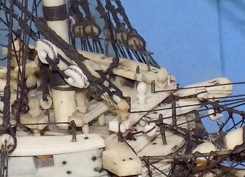
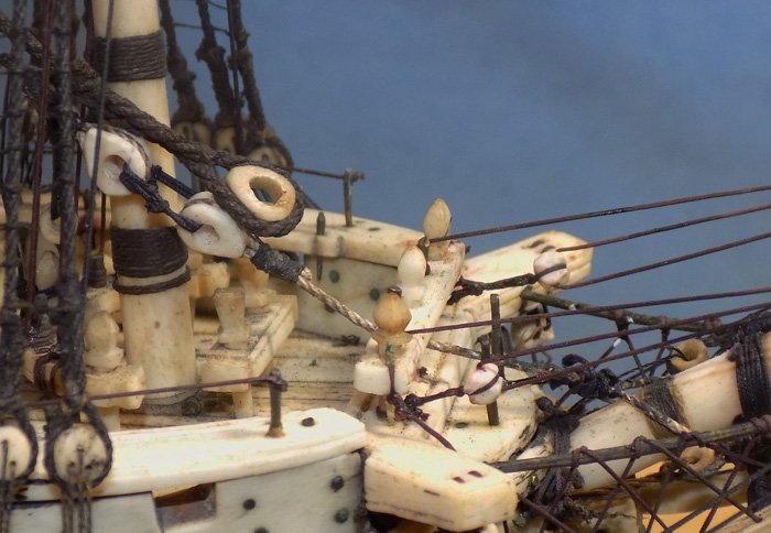
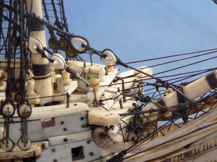
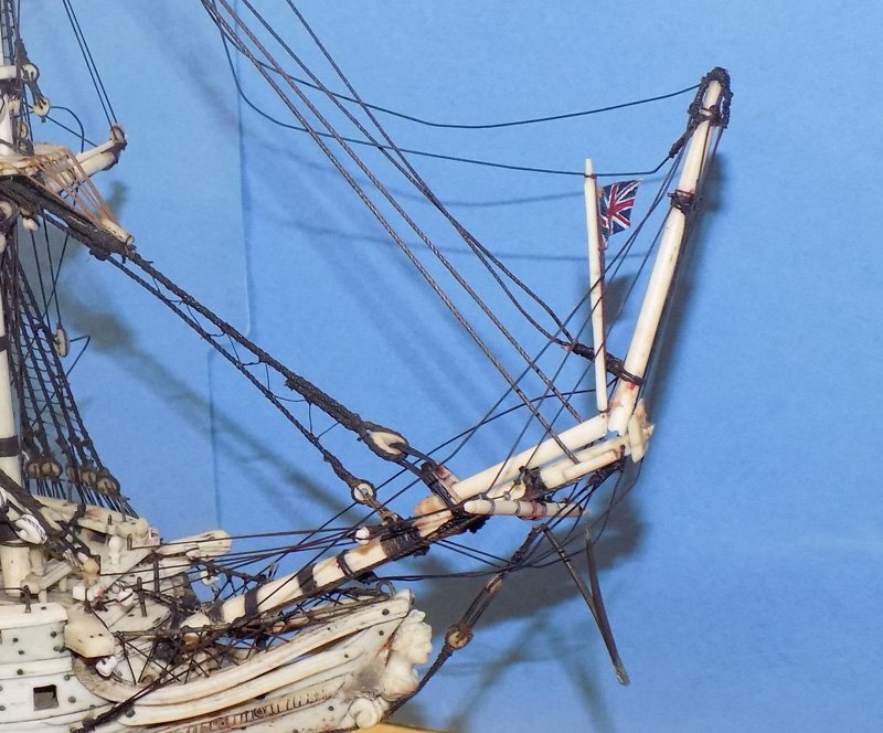
Hi to all – Bob – I’ve passed a lot of water under the bridge since that picture was taken. I really should update it, if I can find a photo that will not scare the kids. Just had time for a quick repair today. The first piece of rigging to repair on the main mast was the mainstay collar. As received the mainstay is one of the better preserved elements of the original rigging. The stay and preventer are both secured to the masthead with eye and mouse fittings. The crowsfoot is properly rigged through a small ivory euphroe. The stay and preventer are appropriately sized as is the snaking line between them. The preventer is properly rigged with a pair of hearts, but it is clear that its collar is a replacement. It is the wrong color and it runs badly. Its seizing around the bowsprit is particularly sloppy. On the mainstay the two hearts are still attached to each other by the lashing, but the rest of the collar that should run from the lower heart to the bowsprit is gone. I carefully cut through the lashing between the hearts and cleaned up the upper heart. In this photo you can see how kinked the preventer collar had to be to run under the pinrail. I’m not sure why any restorer would do this. I seized the heart into a line that matched the diameter of the other collar, but was the proper color. I passed the running end around the bowsprit and seized it so it could extend up toward the matching heart with a reasonable gap between. I thought about doing the collar in a more accurate manner, but decided to match the style of the earlier repair. I lashed the two hearts together and this little repair was done. More soon. Dan
- 95 replies
-
- 18
-
-
- POW
- Bone model
- (and 2 more)
-
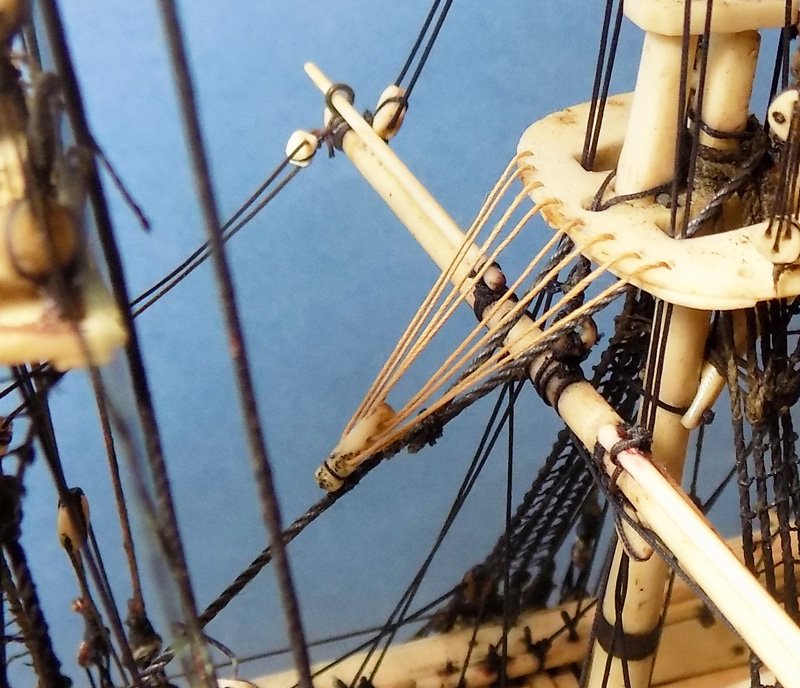
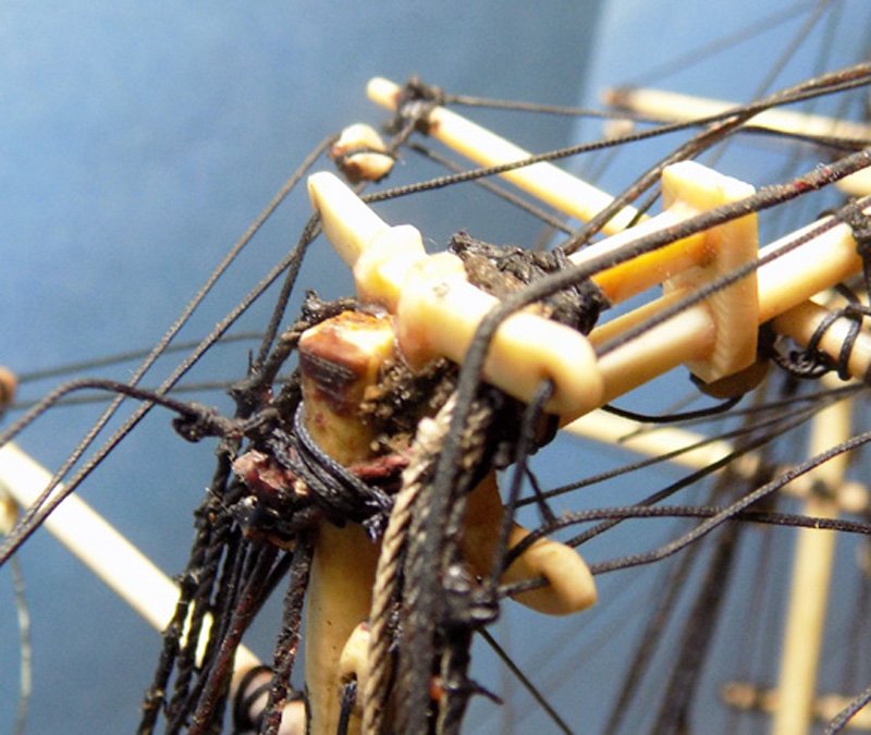
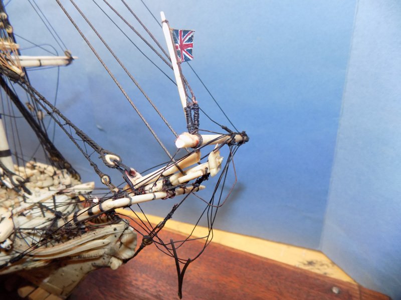
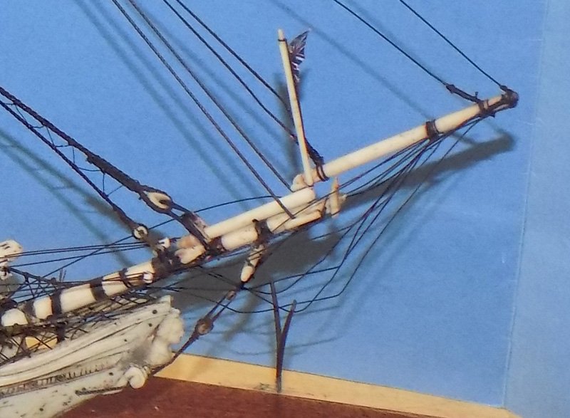
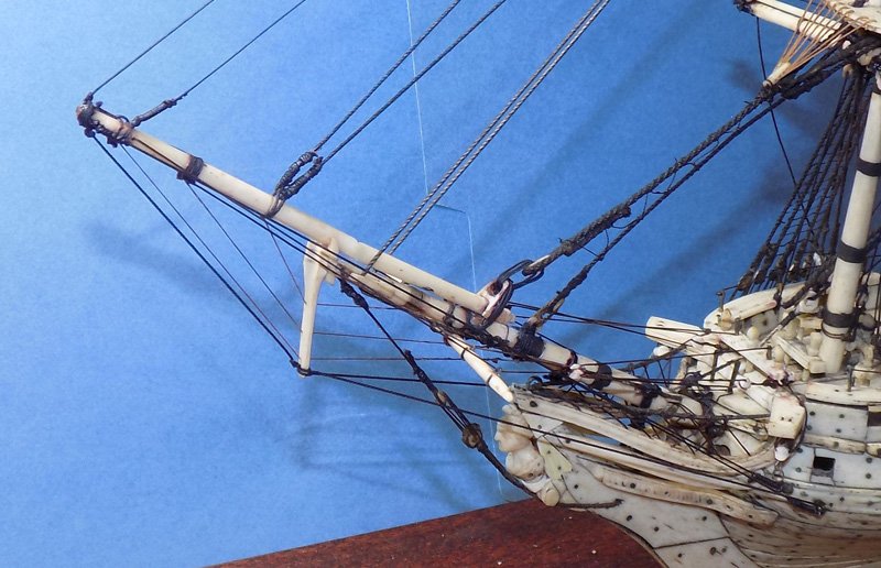
Hi again to everyone – Thanks as always for the compliments and interest. Tony – I may try CPES the next time I have to make sails. I have never been completely satisfied with the stiffeners I have used in the past. It should work on thin fabric too, yes? Bob – Yes, victory it is! But I work in a space that is barely 6 feet by 7 feet with only one small French door (it used to be a walk-in closet). I am also 70 with a bit of asthma. I use solvent based materials only when there is no water based alternative. If I do, I clear out for a while until a small fan can clear the vapors. As you said, it’s all about common sense. Back on the model, with the lower rigging strengthened and repaired, I turned to the first break, the bowsprit. As it came to me the jib boom was broken right behind the bowsprit cap with the martingale detached and hanging only by its rigging. To test some ideas, I moved the broken forward piece around a bit and found that I could lay it in place on top of the aft piece, but the stays and other lines had shortened so they had to overlap about 2mm. I could also set the heel of the broken piece in place, but then trying to pull down the forward end would overtighten the lines and pull the fore topmast much too far forward. To mend the break I first cut off the martingale and all the raffle of lines that led to it. To get the pieces to fit I gently ground off about 1mm from each face and flattened them so they met snugly. Then I drilled into the ivory on both ends. I knew that with such limited mobility I could only use a very short length of brass rod across the joint. It was more used to locate and keep the two pieces centered than to provide any real strength against a future impact. Once in place with the brass rod inserted I gently clamped them against a straight piece of wood. When I was satisfied that they formed a straight line I bonded them with cyano. This is one of only two places where it is used. The other is to stiffen the ends of rigging line that has to feed through small holes, and is then discarded. Once the cyano had cured there was only a little groove where the pieces met. I took a sanding wheel and ground some ivory into a powder. Mixed with MC it made a nice filler. Here is how it came out. As mentioned, I was not at all happy with the “Y” shape of the martingale and the fact that it was not made of bone or ivory. I consulted my sources and, although large models of ships of the line had “V” shaped martingales, the most common was a simple spike rigged to the boom, the bowsprit, and the hull. You can see these features in the models in the Lloyd book much like these. Although many martingales are mounted under the bowsprit cap, the stub of the bowsprit tenon that extended through the cap suggested that the martingale here had originally been mounted to the front face of the cap and had been vertical. I decided that this solution had plausible deniability and went with it. I took some ivory and cut a piece the width of the cap and a length that looked right for the size of the model. I carved it down to a round spike with a mortise in the head that fit the bowsprit tenon. Three holes were drilled for rigging lines at approximately equal spacing. It was mounted to the cap with glue and metal pins, then martingale guys were made up of dyed linen line. One ran from the tip of the jib boom to a notch at the base, and then two went to eyebolts already in place on either side of the hull. Smaller lines were run from the boom through the holes in the martingale and tied off to the bowsprit. Between the guys and the inner rigging they form a triangular truss arrangement that would have strongly resisted the pull of the headsails. The various foremast stays that led to the bowsprit and jib were tightened by sliding their collars out on the boom or up on the mast till the stays were barely straight. This left just a bit of slack for further tightening when the mainmast is fixed and its stays that run to the foremast are rigged and tensioned. One break fixed, three to go. Stay safe Dan
- 95 replies
-
- 17
-
-
- POW
- Bone model
- (and 2 more)
-
Bob - Thinned CPES sounds like an excellent solution, but not for this problem, I think. Unfortunately there is no such thing as a "well ventilated area" in a Brooklyn apartment. I will stick with the water based products. Thanks for the suggestion. Dan
- 95 replies
-
- 5
-
-
- POW
- Bone model
- (and 2 more)
-
Hi again – Druxey – Now you tell me . . . J Tony – Thanks for the suggestion, but I only use epoxy for metal-to-metal joins, or making ocean spray (a process that I have not perfected). It cures very hard and brittle, in my experience, though I have never thinned it. I have no idea what solvents like acetone might do to 200 year old linen, and I don’t think I will try it on someone else’s model. Mark – That’s the s*******, c*********, r*****est compliment I have ever gotten. Back in the drydock, just one small repair today - the forestay preventer that I had broken before realizing how fragile the lines were. Notice how nice the cable is that makes up the stay and how neatly the heart was turned in. This must have been quite the nice model when it was new. The lines were painted with MC and allowed to dry. I did not try to paint the snaking lines, but again let capillary action take some of the MC onto them. I cut a length of 0.010” line to use as a splint, long enough to span the two breaks with a bit on either end. It was painted with full strength PVA and gently lifted up from underneath. I attached it at both ends, the tackiness of the PVA holding it in place. Then I could gently maneuver the middle piece until it lay on the splint in the gap. After the PVA cured it became completely clear and I gave the repair a top coat of MC. I also painted the snake lines which were now strong enough to hold up. Thanks, as always, for the likes. Back soon. Dan
- 95 replies
-
- 14
-
-
- POW
- Bone model
- (and 2 more)
-
Hi to all – Thanks again for all the likes and comments. Barkeater – yes, I use fly tying thread when I want a very smooth seizing on a small scale stropping or splice. It mikes down to 0.003”, and even less if you separate the several strands that make it up. But here the seizings on the model, whether original or repairs, use larger line for those purposes and I will be matching them rather than trying to make improvements. Today I worked my way around the lower shrouds, stiffening them and repairing ratlines as before. I came to the main lower shroud on the starboard side. I had noticed before, when I received it, that the lanyard of the center deadeyes was completely broken, although the lanyards on either side were still whole. A number of the ratlines, especially at the bottom, were broken. After stabilizing everything with MC I slid a Post-it behind the gang to help me see what I was doing. I knew that I would not be able to access the back of the upper deadeye to lace the lanyard. There was almost no room between the deadeyes and the hull so I would need to twist the shroud around, which would certainly break more of the ratlines, if not the shroud itself. All I could do was to fake the lanyards enough to fool the eye. First I removed the broken lanyard pieces. I took a length of the very thin linen line that had been dyed black, then soaked it in PVA and hung it with a weight on the end. It dried stiff and straight. I measured and cut three short lengths and glued them to the face of the deadeyes. I had hoped that these three would be enough to visually look like a lanyard, but it looked empty compared to the lanyards to either side. So I took three more lengths of the stiff line and attached them to the backs of the deadeyes. This last took lots of patience, some bad words, and a bent paper clip to nudge them into place without turning or twisting the deadeyes. It did not come out as perfectly as if I properly laced the lanyard, but considering the variations in the other lanyards it fit right in. It is solving these small individual puzzles that I like best about restorations. After this I could treat the rest of the shrouds with MC and lay on the Mettlar threads over the broken ratlines. Getting the lowest two or three sets of ratlines across the shrouds strengthened the entire web and hopefully will prolong the life of all of this rigging. And hopefully the rest of the repairs will go as well. Stay safe Dan
- 95 replies
-
- 15
-
-
- POW
- Bone model
- (and 2 more)
-
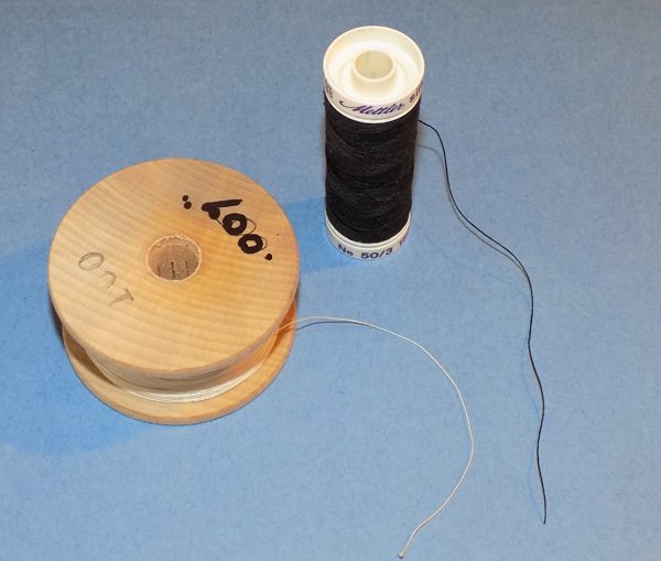
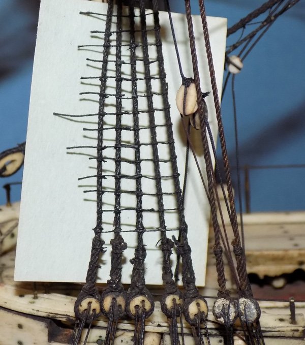
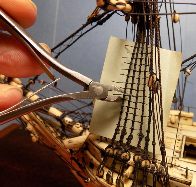
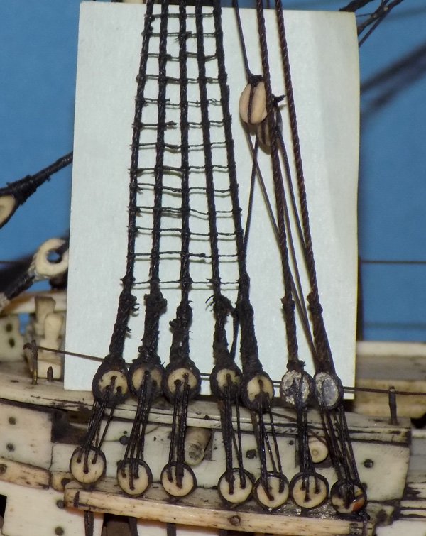
Hi all – After reviewing all the experiment results and considering Druxy’s suggestion, I decided to go with a combination method. I will use the methyl cellulose (MC) on lines that will not have to be manipulated, like the lower shrouds and stays. I will need the increased flexibility and strength that the PVA will give me on the lines that I will have to move around when I repair them. If needed I will tone down any shiny finish with an overcoat of the MC. This should give me some additional strength as well. So I took my softest sable brush and started to paint the MC onto the foremast lower shrouds. Disaster! Despite how gently I tried to apply the liquid to the forward shroud and ratlines, the ratlines crumbled all down the length of the shroud. Of course I stopped immediately. It appears that the ratlines are so thin and so cooked that they must be held together by will power alone. I tried blowing on one and it crumbled with just a moderate puff. To deal with this I thinned the MC some more, then painted it onto only the shrouds, hoping that capillary action would infuse the ratlines from the shrouds both left and right. I tried it on the rest of the lower foremast shroud gang and happily got good results. No more of the ratlines broke and, after the MC cured, I found that the ratlines were now strong enough to give them a second coat of MC without further damage. Now I had to repair the damage that I caused, and to fix other ratlines that had broken over the years. I wanted to use linen line, but ran into a problem. Linen makes for a pretty stiff thread. Even in the smallest diameter that I have, 0.007”, it acts like steel cable at these small scales. You can see how it does not curve compared to my softest thread, Mettlar’s silk finish embroidery thread. It is a mercerized cotton product, not linen, but I don’t think I will have to worry about shrinkage in this use. It has a bit of an irregular finish, but the 50/3 size generally mikes out to between 0.007” to 0.009”. I cut short pieces of the thread and soaked them in thinned PVA. Carefully laying them across the gaps they were smoothed down using a wet brush and the tip of a dry toothpick. After drying I gave them a coat of MC to tone down any shine. Once this was dry the extra ends were trimmed with a sharpened cuticle clipper. I use this tool from the cosmetics counter in almost all rigging situations. It cuts cleanly, with the cutting edge laid very close to the knot/junction, and without the danger of a wayward blade slicing through a line that I want to keep. Here is how it came out. There are a few tiny stubs where the new lines overlap the old ones, but they are only visible under magnification and then only when there is a contrasting background like this pale Post-it note paper. Other ratline repairs were needed from causes other than my clumsy hands. Here is how I found the main lower shroud gang on the port side. On the left of the photo you can see that the first and second shrouds have somehow been reversed. The forward shroud is twisted and at the masthead actually runs behind and aft of the second shroud. This must have put increased stress on the ratlines between them. At the upper right the brace for the lower mizzen yard is rigged, properly, to the aft main shroud. But the line is a replacement (it is a slightly different color) which shrank and pulled on the shroud, breaking the ratlines around it. And here it is after repairs. The yellow color is because I shut down the camera flash and used only and incandescent bulb. The picture is less confusing when there are no shadows of the ratlines on the paper backing. I did this for all the lower shrouds and ratlines. Here is the port lower mizzen gang during repairs and after. There will be many more repairs needed on the topmast shrouds, especially those on the broken main and mizzen masts. But those are for later. Now I need a stiff drink. More soon. Dan
- 95 replies
-
- 14
-
-
- POW
- Bone model
- (and 2 more)
-
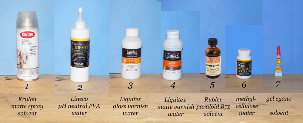
Hi again to all – Thanks for all the likes and comments. I love it when there are wider topics discussed in a build log than just the building. The past several days were spent trying out 7 different glues and varnishes to see if they could help the original rigging. I was looking for a liquid which can be painted on gently and which will strengthen the lines and make them flexible so they do not break when they have to be manipulated to fix the current problems. Here they are. I tried to set up as wide a range of solutions as I reasonably could. If there wasn’t a suitable one in this group then there might not be one. Next I needed something to test them on. The original rigging lines were probably made of linen. Every time that similar old lines have been chemically examined, as far as I know, they turned out to be linen. It was readily available in England at the time since it was made from flax plants which grew there. Cotton was scarcer since Egypt was in French hands most of this time. Linen is also quite dimensionally stable, so rigging lines do not sag or overtighten. Fortunately, I had snapped up a collection of linen line spools about 20 years ago which includes diameters from 0.007” to 0.048”. I use them for all of my museum work that requires rigging. Although most of it is very white, it dyes black or tan quite easily and permanently. To simulate the cooking that the original lines had endured over the years, I took lengths of 0.02” and 0.04” lines and baked them in the over overnight at 350 degrees. Nothing! They came out hot, but as flexible as before. The same thing happened at 450 degrees. Finally, I simply wrapped the lines in foil and set the packet on top of the naked flame of the gas stove. In a few minutes wisps of smoke started coming out of the seams. I turned it over for another 30 seconds then removed it from the heat. When it was unwrapped the lines had been blackened and charred, just as I hoped. After cooling I tried one of the thicker lines and gently pulled it along its length. It took little effort to break the line, with the ends, under magnification, looking a lot like the ends of the broken rigging on the model. These would be acceptable stand-ins for testing purposes. Now that I had my test materials I took seven short pieces of both the large and small diameter lines and mounted them on a piece of file folder. Some of the thinner ones were extremely delicate and one broke as I was mounting it. Then each was painted with the liquid corresponding to the numbers on the composite photo. After they dried overnight I examined them under magnification and then tried to bend each around a ¼” diameter dowel. Here is the photo of the results. What I found was as follows, recognizing the limitations of my not very precise or controlled materials and methods: 1. Krylon spray – I decanted some and painted it on with a soft brush. I worried that the power of the propellant might damage the smaller lines, and also that I would not have a lot of control over the application on the actual model. It dried stiff with a matte finish. It did not seem to improve the pull-apart strength of the line, but made it too stiff to bend easily. 2. Lineco pH neutral PVA – It was diluted to skim milk consistency with distilled water and painted on. It significantly improved both the pull-apart strength of the line and was quite flexible when dry. The one drawback was that it dried quite shiny. 3. Liquitex gloss varnish – Painted on direct from the bottle. The result was not very strong, not very flexible, and shiny. 4. Liquitex matte varnish - Somewhat improved strength and flexibility, matte finish. 5. Paraloid b72 – significantly improved strength but not very flexible. Shiny finish. The biggest drawback is that it requires a strong solvent like acetone for dilution or clean up. 6. Powdered methyl cellulose - Dissolved per the instructions in distilled water. It markedly improved strength, had decent flexibility, and dried with a matte finish. 7. Gel cyano – It was laid on as thin as I could with a wooden toothpick so it would not heat up as it cured and damage the fibers even more. It was the strongest in the pull-apart test, but was the most brittle when dry, especially for the thinner line. Shiny finish. The decision came down to two choices, the PVA and the methyl cellulose. I am leaning toward the PVA just because I am very familiar with its properties. On the other hand, the MC could be used to strengthen lines that will not be handled, with the PVA used where the line might have to bend and twist. I am open to any and all further thoughts that you all might have. Stay safe Dan
- 95 replies
-
- 13
-
-
- POW
- Bone model
- (and 2 more)
-
Hi again - I forgot to mention that I am corresponding with Manfred Stein in Germany. He is the author of the book on bone models that dvm27 spoke about. He also has a very nice website that has located many bone POW models around the world and places where you can see them. If you are interested in these singular art objects, here is his URL - - http://www.pow-boneships.de/ Stay safe Dan
- 95 replies
-
- 6
-
-
- POW
- Bone model
- (and 2 more)
-
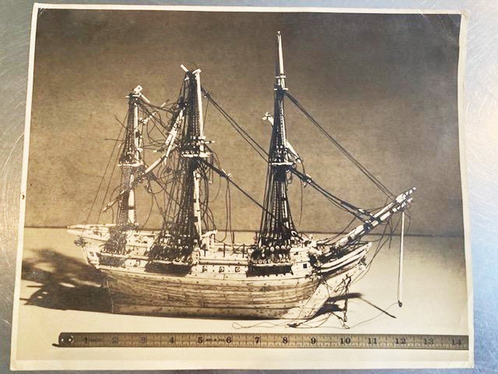
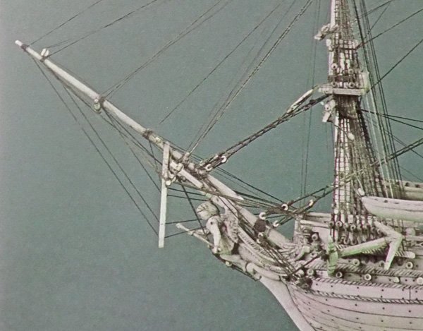
Hi to all - I am back in the shop today and the glues and finishes that I ordered have arrived. I will experiment with them in the next few days and report on my findings. In the meanwhile my client has located some documents from when his uncle had the model repaired in 1956. Here is a photo that the uncle sent to the Mariner's Museum in Virginia asking for information. Notice that the damages are very similar to those that I am repairing - broken bowsprit, main and mizzen masts. The entire figurehead area is missing. I do not know if the bust that is on the model was original or if it was added. The museum was not too helpful, but eventually he located a restorer named C.M. Smeltzer, Jr. at a company called Authentiscale in Metuchen, NJ. I could not find any existing information on either the man or the company. In any event, they reached an agreement that the repairs would cost $210.00 with an additional $40 for a case. I don't know what that converts to in 2021 dollars. I do not have a photo of the model after repairs and before the current damages, but my client is still looking. More soon. Stay well Dan.

- 95 replies
-
- 12
-
-
- POW
- Bone model
- (and 2 more)
-
Cathead - I think Johnny has it right. It was a mostly question of respect for a long time adversary rather than anger at traitorous colonists. This was especially true for sailors, who all understood that their true enemy was not the other fleet but the sea herself. The other issue was one of numbers. The land armies of Napoleon and those of the various opponents, Russia, Austria, Spain, England, etc., generally captured about equivalent numbers of soldiers, so exchanges could be arranged on more or less equal terms. However, the British Navy captured more French sailors by several orders of magnitude than the French captured English sailors. Equivalent exchanges could not be arranged, so the sailors had to be held for much longer periods of time. The British did not want to hold them, and feed them, as evidenced by the wholesale emptying of the POW camps and repatriation of prisoners whenever there was a 'peace treaty' between the countries. Captains Hornblower and Aubrey are always concerned that they will end up on the beach without a command whenever that happened. Barkeater - I have some bone, but it is in large chunks and is much more difficult to work with since it has dried out completely and tends to snap. For these small areas I chose the ivory as being easier to work without much difference in the look of the final repair. I am waiting on the delivery of several kinds of glue/finish products and will report on their suitability when they come in. Till then, stay safe. Dan
- 95 replies
-
- 9
-
-
- POW
- Bone model
- (and 2 more)
-
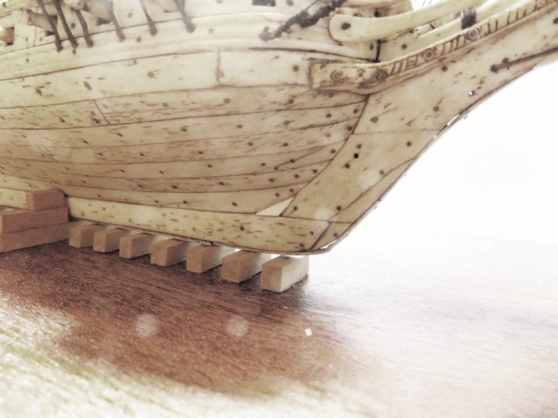
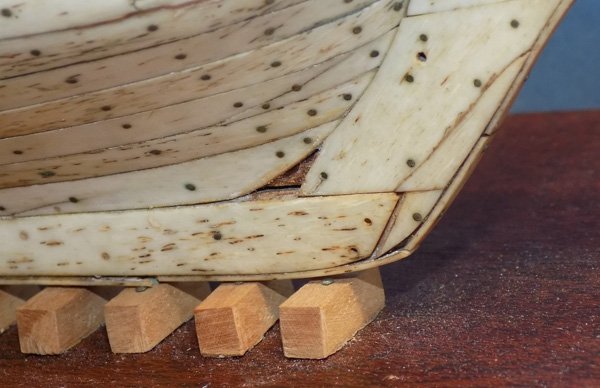
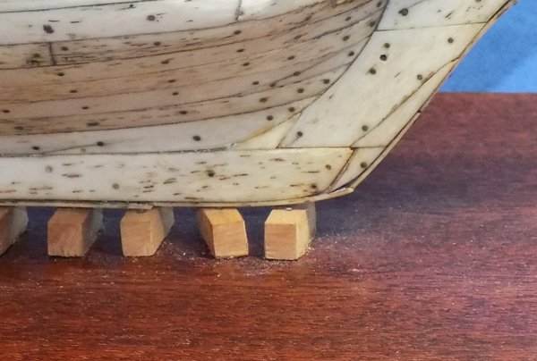
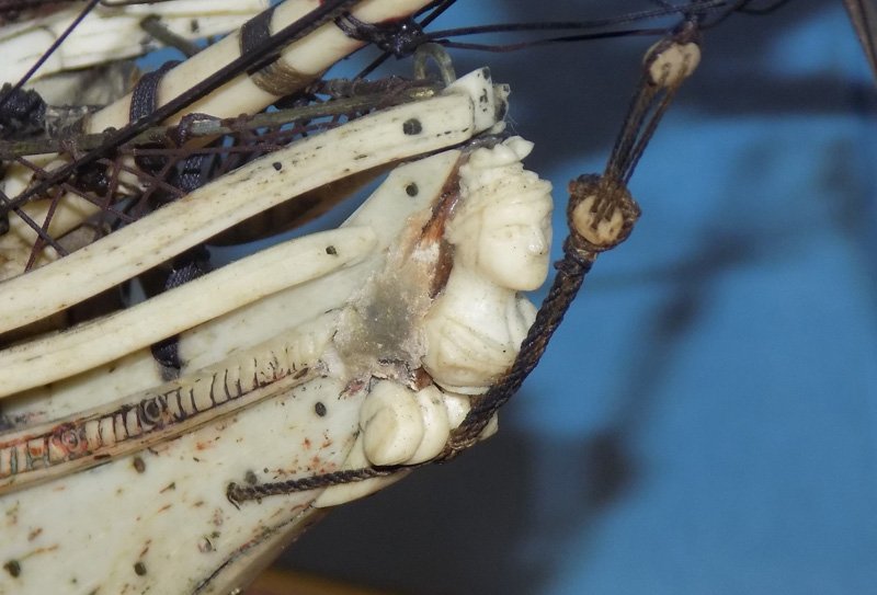
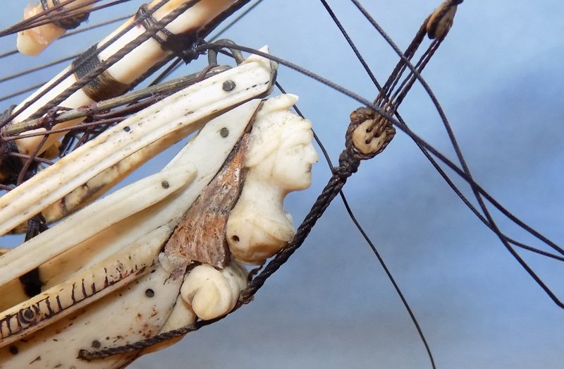
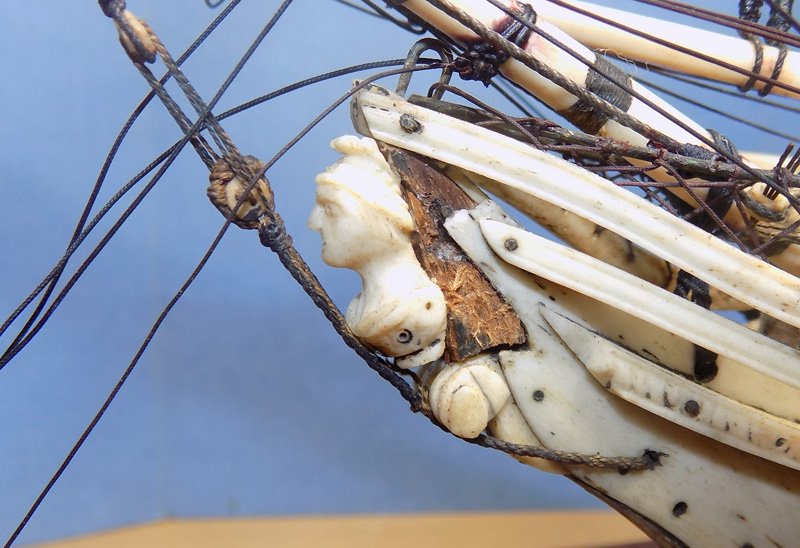
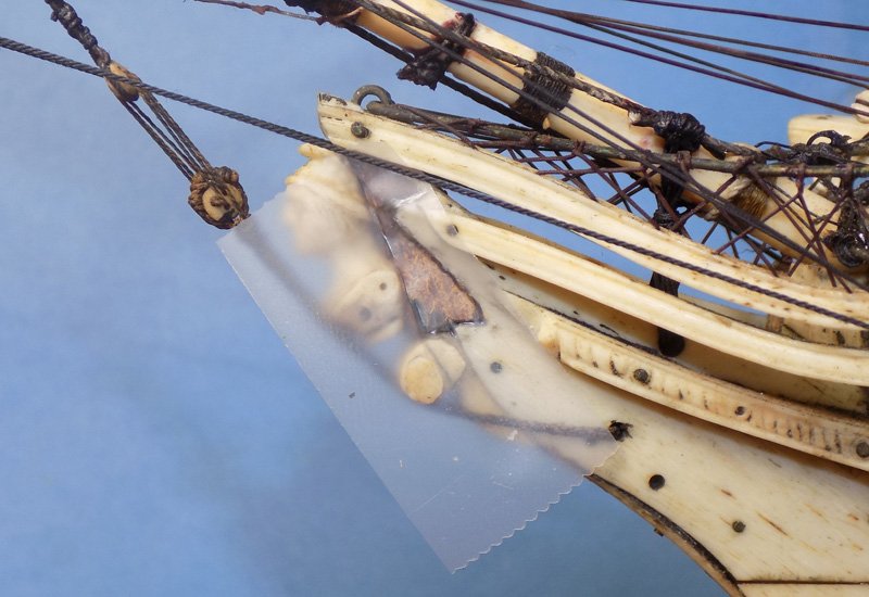
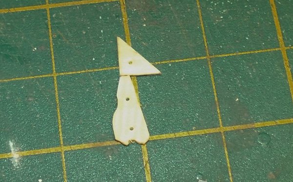
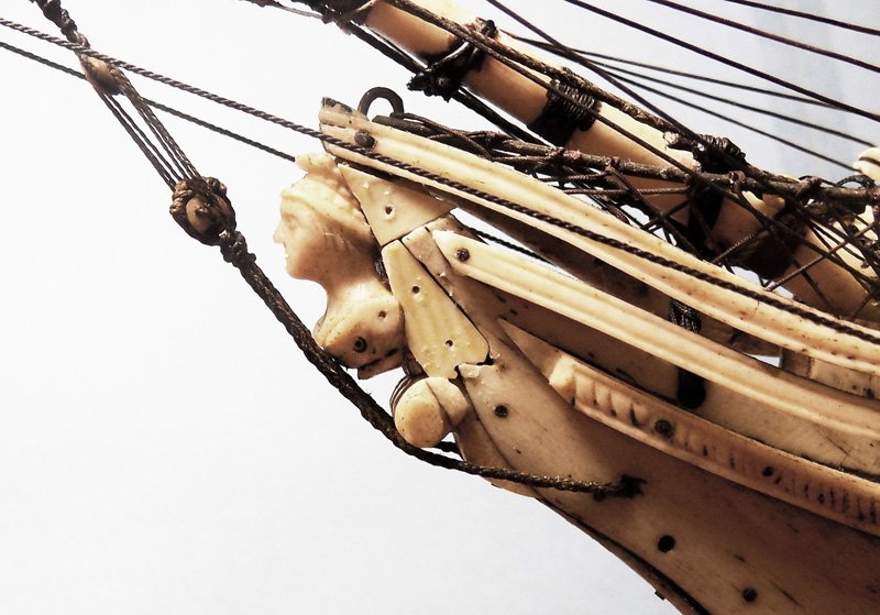
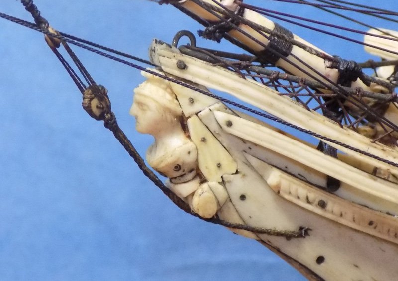
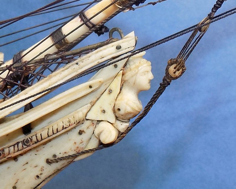
Hi again to all – As you can tell, I really like POW models. I first ran into one at an antiques show that my mother dragged me to when I was about 10. I found that it was pretty interesting looking at old artworks and furniture. But a large, intricate, bright white model of a sailing warship captivated me. When I was told that it was made of bones and rigged with human hair, I begged my mother to buy it. I have no idea why she decided not to spend $7,000 (about the cost of a good car back then) on such a simple request. In the 60 years since then I have learned many things about them, such as that they were not actually rigged with hair, and that I still can’t afford one. I do get a bit of satisfaction in restoring them for others. I have been fortunate enough to be given this pleasant task several times. Each is its own unique fine art object, and each has its unique set of restoration puzzles to be solved. For this one I spent that past two days trying to solve the hull puzzles. The easiest one to access was the small triangle at the gripe where the wide stem plank had lost its point. It had been repaired by replacing it with a piece that was much too white for the surrounding bone planking. I removed the offending triangle with a dental pick. It turned out not to be ivory, as I expected, but was actually a hard plastic. Not very original. The old glue in the corners was removed with the pick and the tip of a hobby knife. To fill the hole I used the ivory top of a piano key. I have a small stash of ivory, most of it whale tooth ivory, from when I was playing around with scrimshaw. It was also too white, but unlike the plastic I could change it. Many years ago I came across an article that recommended using used coffee grounds as an ‘aging’ agent for ivory. Fresh grounds have too much acid and volatile chemicals to use for this. I have used the method before with good results. Here is the key with its left end having been buried in damp grounds overnight. After drying out, a piece of the stained side was cut and fitted. It was installed with PVA since it is mounted on the wood of the stem. I next turned to the figurehead. It had obviously suffered some serious damage in the past. Although the figurehead itself was in pretty good shape, the area behind it was missing all of the hull planking. It had been crudely filled in with a putty of some kind that was tinted grey or had aged that color. As I said in an earlier post, I also did not like where the head was fitted. My understanding is that the back of the bust’s head should be at the level of the topmost rail, which is why it is called the ‘hair rail’. This bust was mounted at least ¼” too low. Using rotary tool I carefully ground away the putty. I used a flat bottomed bit to help insure that I would not unintentionally dig too deep into the original substance of the model. With the putty mostly removed I found that the entire tip of the stem was a replacement, being a separate piece of wood carved to fit. Removal of the putty also revealed a hole in the shoulder of the bust, probably indicating where a separate arm once fit. It was while taking this photo that I realized that there was a gap between the bust and the scroll which the bobstay runs against. On the port side the putty was similarly removed. It revealed a clearly broken end to the upper planking. It must have been quite an impact to do that much damage. But the bobstay appears to be original and shows no break or repair. How that could be possible I don’t know. The loose lines that are in the photo are some replacements that ran to the incorrect and broken martingale. They were soon removed to keep them from getting in the way. I thought about moving the bust up to its proper place and then carving a middle piece, perhaps a dress, out of ivory. But the bust would not come loose with gentle leverage, so I left it in place. All I could do was to fill in the open spaces with new planking. To take the shapes needed I laid on some translucent tape and drew the outlines. The tape was laid on the aged ivory and pieces cut out. I drilled holes for metal pins that would help secure the pieces to the hull. These are for the port side Here they are test fit, ready for final shaping. And here they have been glued and pinned in place. I also carved a rounded wedge of ivory to fit in the gap below the bust. This is the finished port side And the starboard side. I’m considering scratching some ‘grain’ into the ivory to make it look a bit more like bone, but that may be a bit on the obsessive side. It’s still an option. Stay safe Dan
- 95 replies
-
- 15
-
-
-
- POW
- Bone model
- (and 2 more)
-
Keith - Wonderful work. I am really looking forward to the lacemaking class, whoever teaches it. I confess to learning how to cane a chair for one of my smaller models, but making lace was always beyond me. I just buy wedding veil material or similar from a local fabric store that still has old patterns and weaves. Stay safe Dan
-
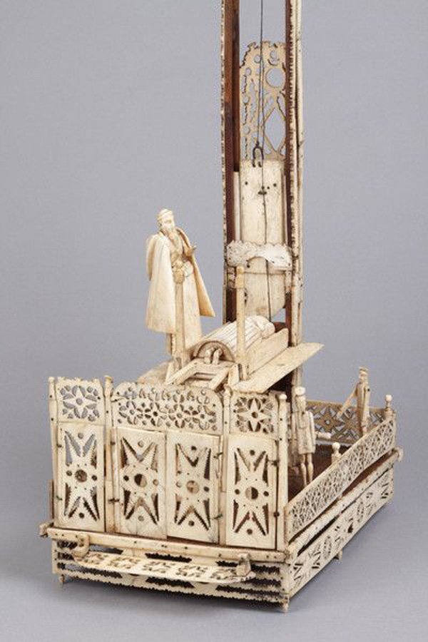
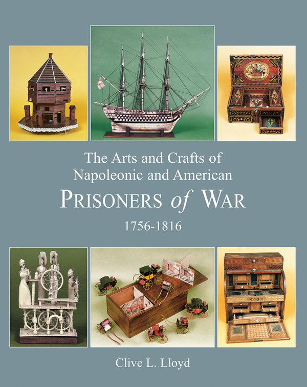
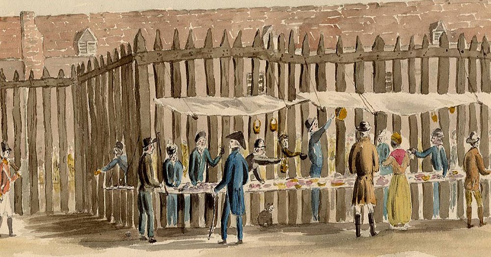
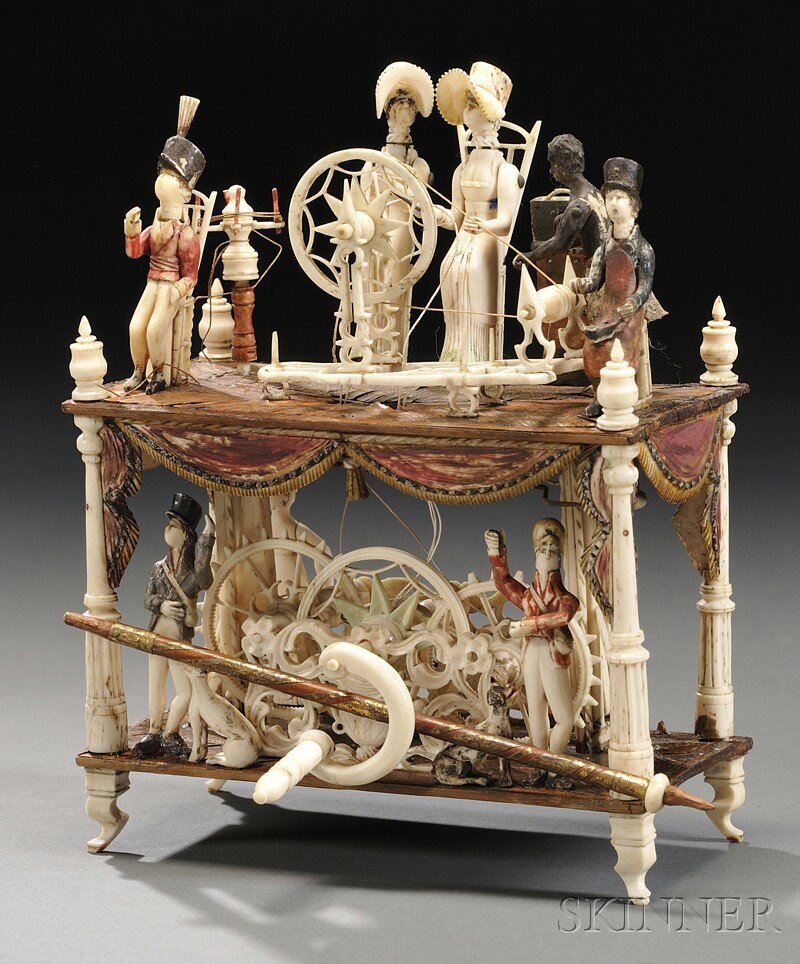
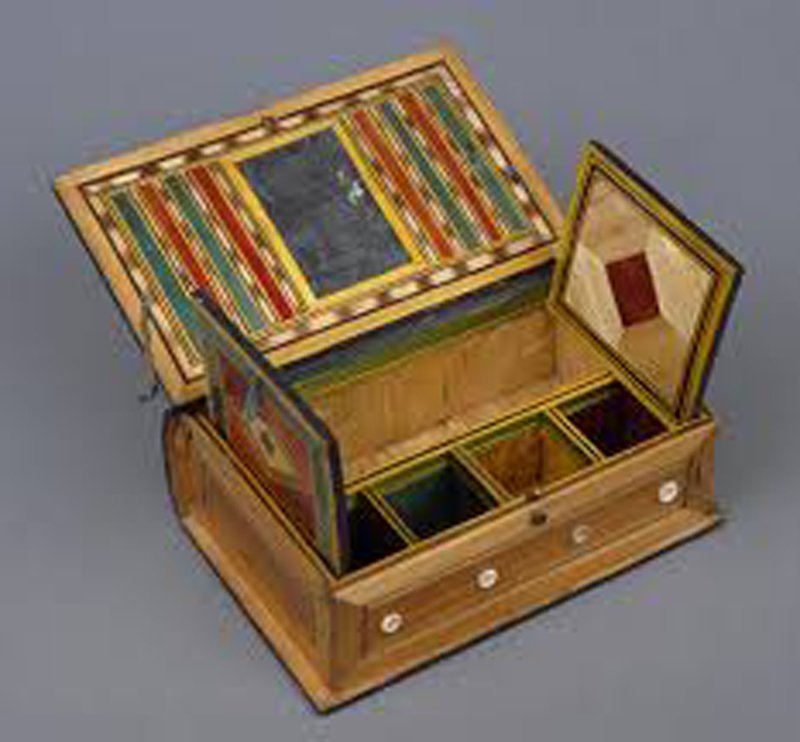
Hi all - Druxey - yes, and thank you . I have ordered some of the glue and will test it with the others that I have. Roger - the conditions of French POWs was not usually that dismal. Yes, the prison hulks were not pleasant, but you do not abuse the enemy's POWs or he may retaliate against yours. In fact, towards the middle of the period most of the naval POWs were housed in large camps like Norman Cross. Think "The Great Escape" or "Hogan's Heroes" rather than "The Bridge on the River Kwai". Officers could give their parole and live outside camp in nearby villages. All sorts of activities and athletics were permitted. There is even evidence that there were fencing lessons. The British also believed in having the prisoners keep busy, so they allowed them to make all sorts of handicrafts, not just ship models. There were bone spinning jennys, bone guillotines, and straw work of all kinds, like this jewelry box. The POWs were allowed on market day once a week to sell their wares to local customers at tables outside the camp stockade. They also sold to merchants and brokers in larger volume. Since they did not have labor costs, and did have lots of time, they excelled at making time consuming products like lace and straw hats. This trade grew so great, since they could easily undercut the competition, that the English lacemakers and straw hatters petitioned Parliament for help and the POWs were prohibited from making them. If you can find it, this is the bible on the POW arts and crafts. Stay safe. Dan
- 95 replies
-
- 17
-
-
- POW
- Bone model
- (and 2 more)
-
Hi all - Thanks for the likes and comments. Phil - I am pretty well convinced that it started out, two centuries ago, as a nice example of a POW model. It has many of the characteristics that I have seen in many museum pieces and under all the restorations there are well-crafted and delicate details. Construction methods match those described in the several books on POW models that I have. Druxey - the HMG glue sounds interesting. I will look into it. Do you know where I can buy some online? Dan
- 95 replies
-
- 4
-
-
- POW
- Bone model
- (and 2 more)
-
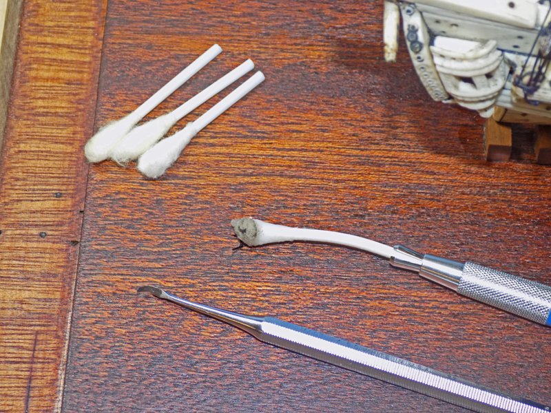
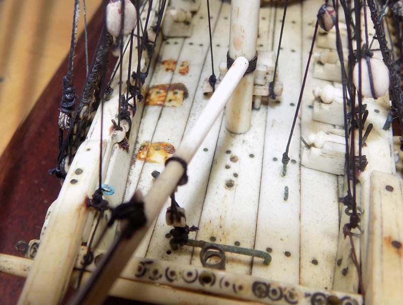
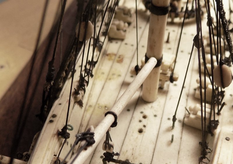
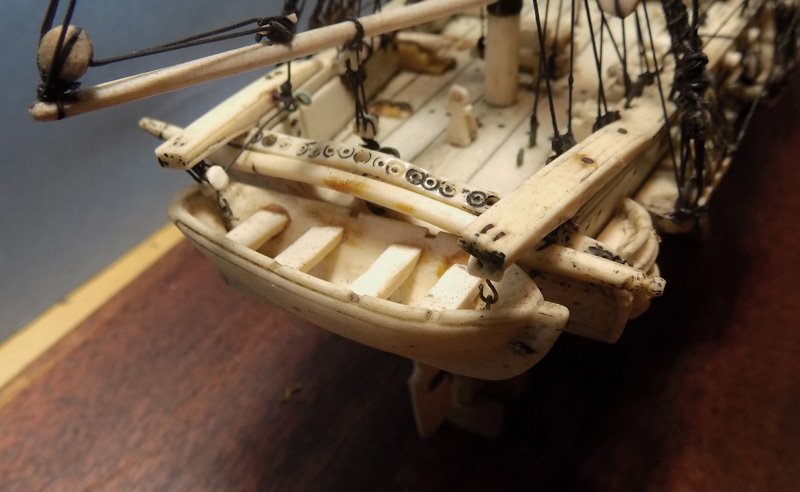
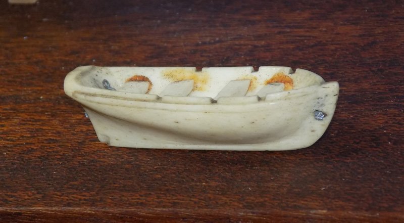
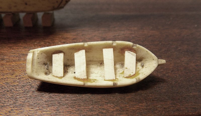
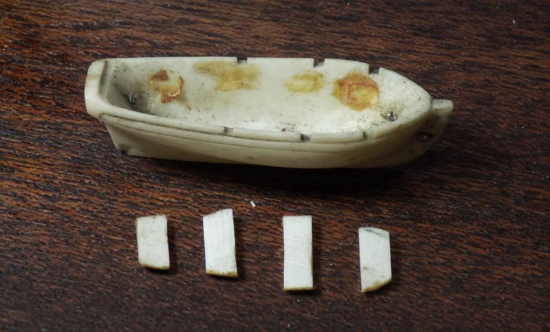
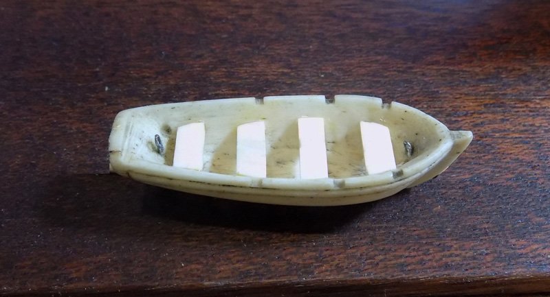
Hi again to all. I spent yesterday working on things other than the rigging. First I did some cleaning. The hull and deck were pretty clean, being protected from dust by the case. I still wiped them down with some distilled water, no soap or solvent was needed. As a mop I used half of a cotton swab in a drafting pencil handle. It is important to use the kind with a paper shaft rather than the plastic one. As can be seen in the picture, paper ones can be bent so it sits flat with the handle angled up so it can reach through spaces in the rigging. In this configuration it also can slide under deck fittings like the bitts and pinrails. The metal tool is a plaque scraper that I got from my dentist. There are lots of dental tools and supplies that transfer easily to ship modeling. I asked mine to set them aside when he was going to replace them anyway, and he was happy to do so. I used it as a scraper for the dried glue and it worked quite well. Here are the spots where the three loose cannon came from, and the same area after scraping. I went around the ship, as much as was possible, and removed the worst of it where possible. After cleaning I worked on the ship’s boat. It was detachable, so I did not have to worry at all about touching the rigging. Here it is, as received, hanging in the stern davits. I was a bit concerned that the thwarts were replacements since they do not appear to match the color of the boat’s hull. I gently bent the hooks open and slid the boat off. Now I could see that the thwarts had been glued in with the same stuff that was scraped off the deck. From this angle it was even more evident that the thwarts did not match, either in color or in the quality of workmanship. Their ends are ragged and they do not sit perpendicular to the centerline. The dried glue was little obstacle to removal of the thwarts using only gentle leverage. The inside of the boat’s hull was scraped clean and the thwarts sanded lightly to remove discolorations. With a few tweaks of the ends they were straightened out and levelled. I reattached them using small drops of gel cyano glue. It is the best that I have found for bone-to-bone, and bone-to-ivory, connection. It is stronger and more rigid than PVA, drop for drop, so I can use less and not leave a glue mound. It is also very clear and stays that way, at least over the 35 years that I have evidence for. But it can be brittle, so where the joint will be under strain I also give it a second thin coat of PVA as a shock absorber. That was not necessary here. I think the boat is much improved. I just hope the rest of the repairs go as well. Dan
- 95 replies
-
- 20
-
-
- POW
- Bone model
- (and 2 more)
-
Hi Vaddoc - Yes, all good ideas. I will be experimenting with cyano, PVA, shellac and other glues and finishes. I worked with hair spray once on some scale trees in an architectural diorama which were losing their leaves. It worked quite well since I could spray it gently using several coats. I recall that it dried a bit stiff, but that was not a problem in that setting. I'll report my findings soon. Dan
- 95 replies
-
- 5
-
-
- POW
- Bone model
- (and 2 more)