shipmodel
-
Posts
941 -
Joined
-
Last visited
Content Type
Profiles
Forums
Gallery
Events
Everything posted by shipmodel
-
 Truly a tour de force, Keith. Bravo !!! (I'd put in more exclamation marks, but that might be silly.) Dan
 -
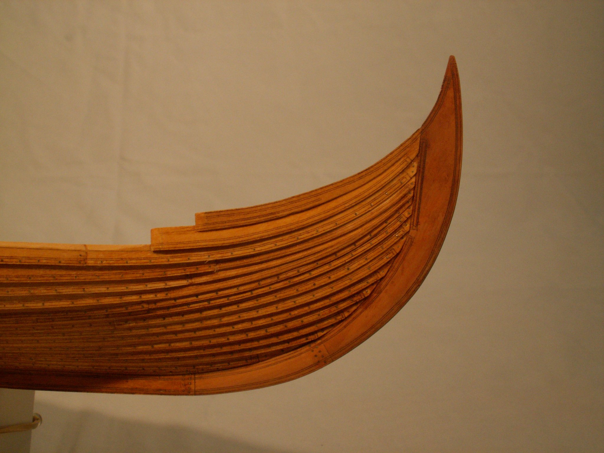
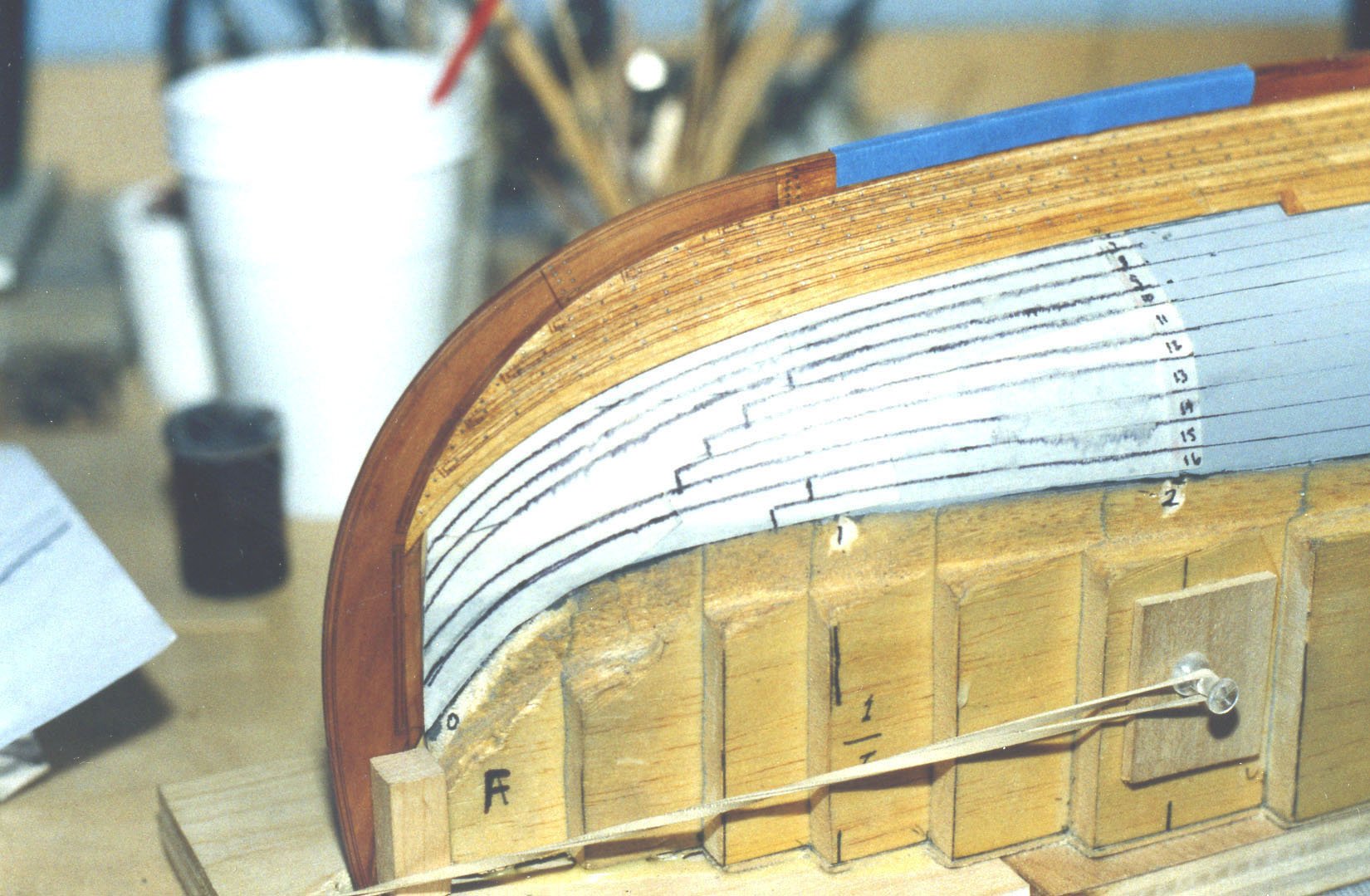
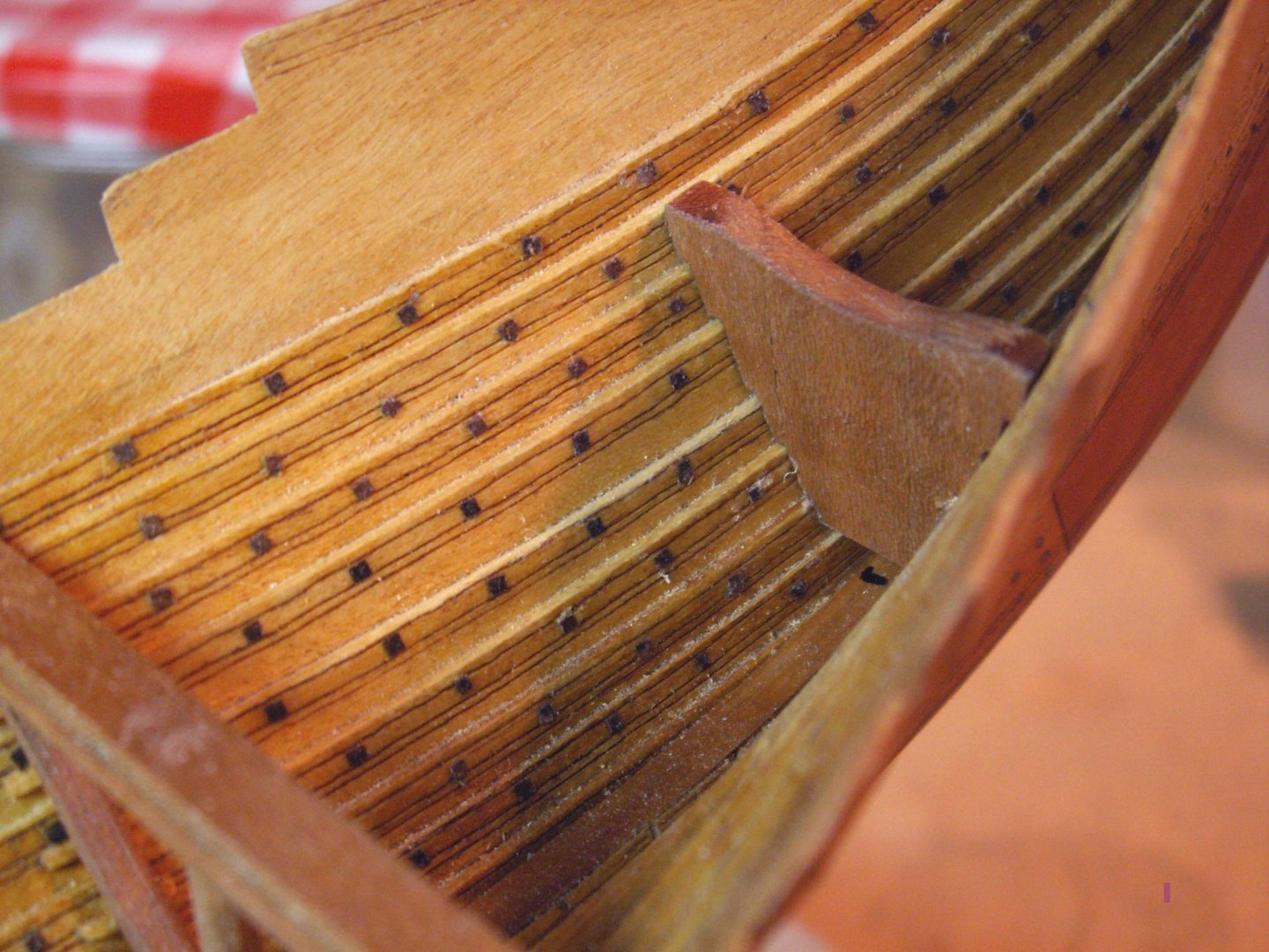
Hi Vaddoc - This is an interesting project and I am enjoying following along. I am fascinated with learning what CAD can do - and not do. I have done several lapstrake boats/ships and I have a few suggestions, if I may - 1. The garboard should not come up higher on the bow. Bringing it up typically increases the bend required in the rest of the planks 2. Try to plan out all of the planks before cutting wood. You will certainly need to tweak the strakes as you install them, but it will give you a good starting point. 3. A 2mm overlap is good. I found that scribing the overlap on both sides of both edges of each plank kept me from wandering. Here are some photos of my Gokstad ship under construction. The overlap was just about 2mm and there were 16 strakes, so I hope it can give you some ideas. Best of success. Dan


-
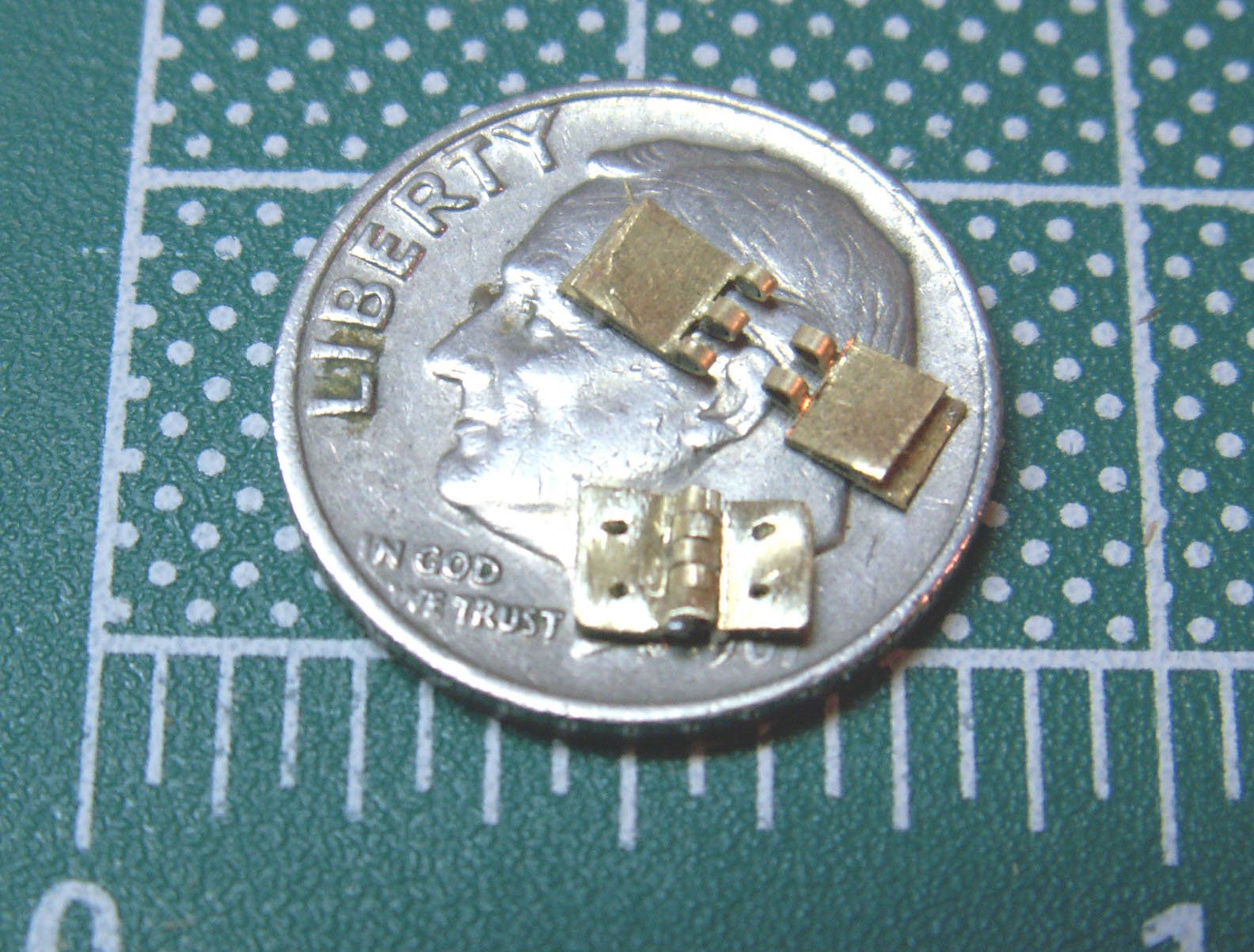
Hi Michael - I left the soft iron wire in the hinges when I cut the slots on a Preac table saw mounted with a metal cutting blade. Leaving the wire inside kept the brass from collapsing or deforming as it was cut. It took a bit of experimentation with jigs and stops, but with them I could get a consistent depth and width to the slots. This was done as a long length of brass, like a piano hinge, which helped a great deal in handling the piece. Then the individual hinges were parted off and the inner wire pieces were pushed out. Hope that clarifies things. Dan
-
Hi Michael - Beautiful work, as always. Not just the metalwork, but the paneling as well. I used a very similar method to build the hinges for the companionway on the yacht America. To install them I used eyeglass screws, then filed down the heads. I like them because the threads can be bedded into epoxy for a really secure hold. (Also because, unlike an expert like you, I can't make my own . . . ) I am truly enjoying following along with you. Dan

-
I thought it was something like that. Looks like a good solution. Dan
- 2,699 replies
-
- 3
-

-
- heller
- soleil royal
- (and 9 more)
-
Hi Marc - I was wondering why you had to make your windows 4 panes tall x 4 wide, rather than the 3 x 4 of the Berain drawing? Was this to keep the pane sizes approximately the same for the upper windows? Dan
- 2,699 replies
-
- 3
-
-
- heller
- soleil royal
- (and 9 more)
-
Hi Marc - Well thought out, as usual. The a-symmetric sow's ear is looking silkier and silkier. . . When you come on Tuesday you can look through my collection of brass, aluminum and plastic tubing. Some goes down to 1/32" o.d., and I even have some hypodermic needles that can be cut up to form the gudgeons and pintles. Feel free to take what you need. Dan
- 2,699 replies
-
- 4
-
-
- heller
- soleil royal
- (and 9 more)
-
Hi Marc - Once again your excellent carving talents are amply demonstrated. I look forward to seeing her in the flesh next week. When I am carving figures, whether human or animal, I also start with the eyes. Pretty much everything else can be adjusted or reshaped around them. As they say, the eyes are the windows to the soul, so they have the greatest visual impact of any facial feature, even more than Cyrano's nose. Dan
- 2,699 replies
-
- 4
-
-
- heller
- soleil royal
- (and 9 more)
-
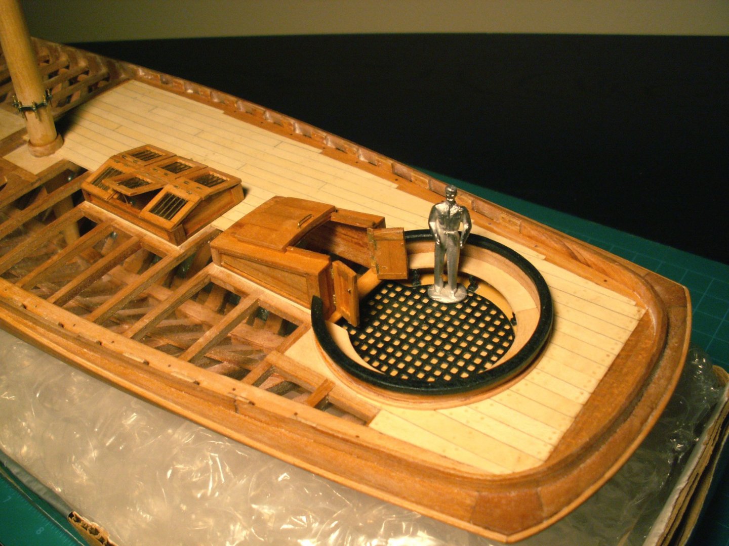
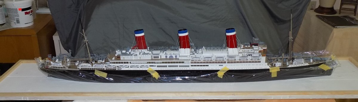
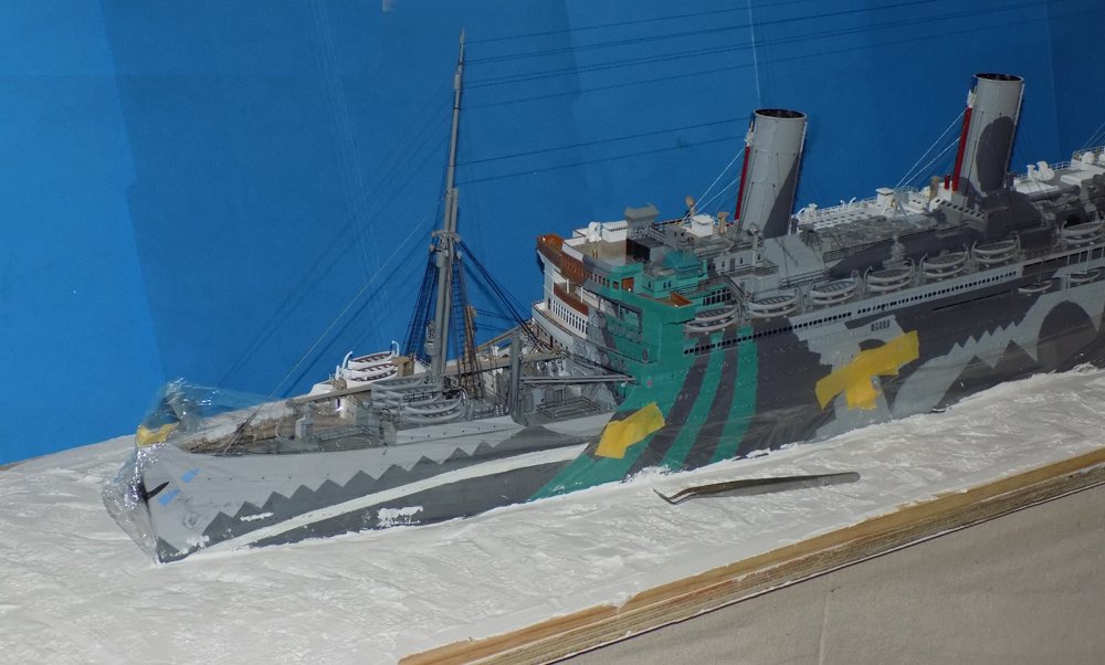
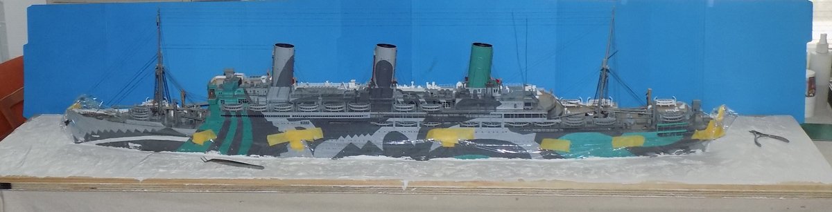
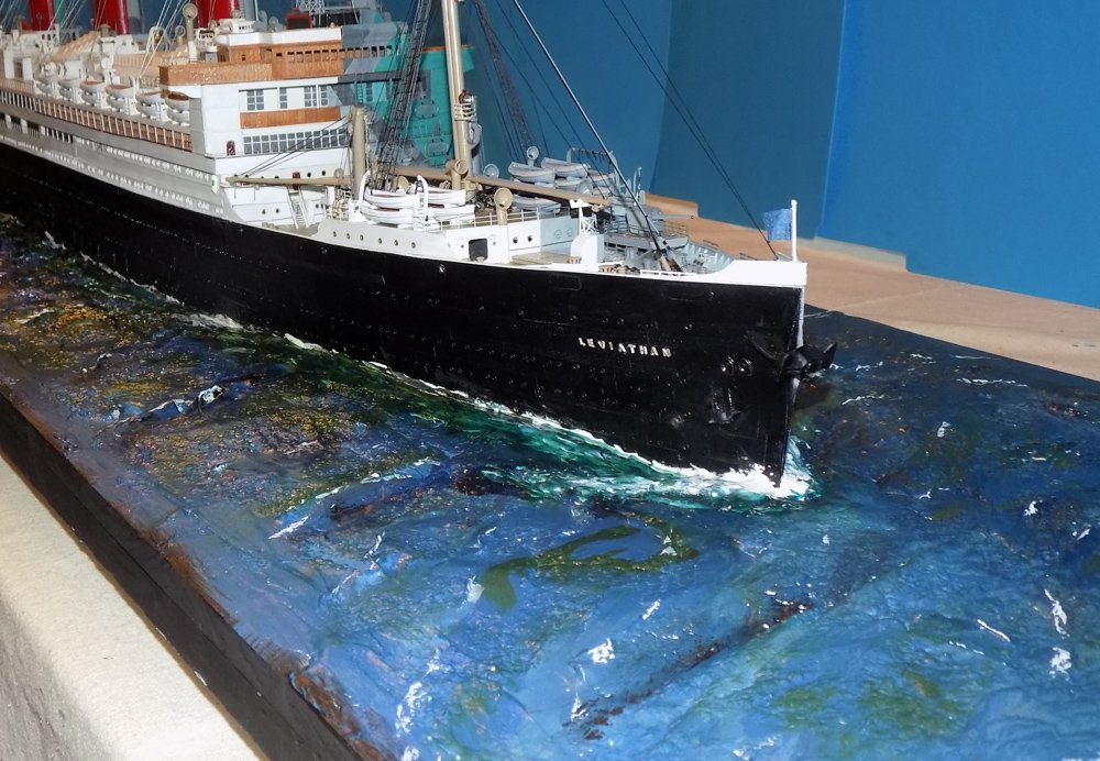
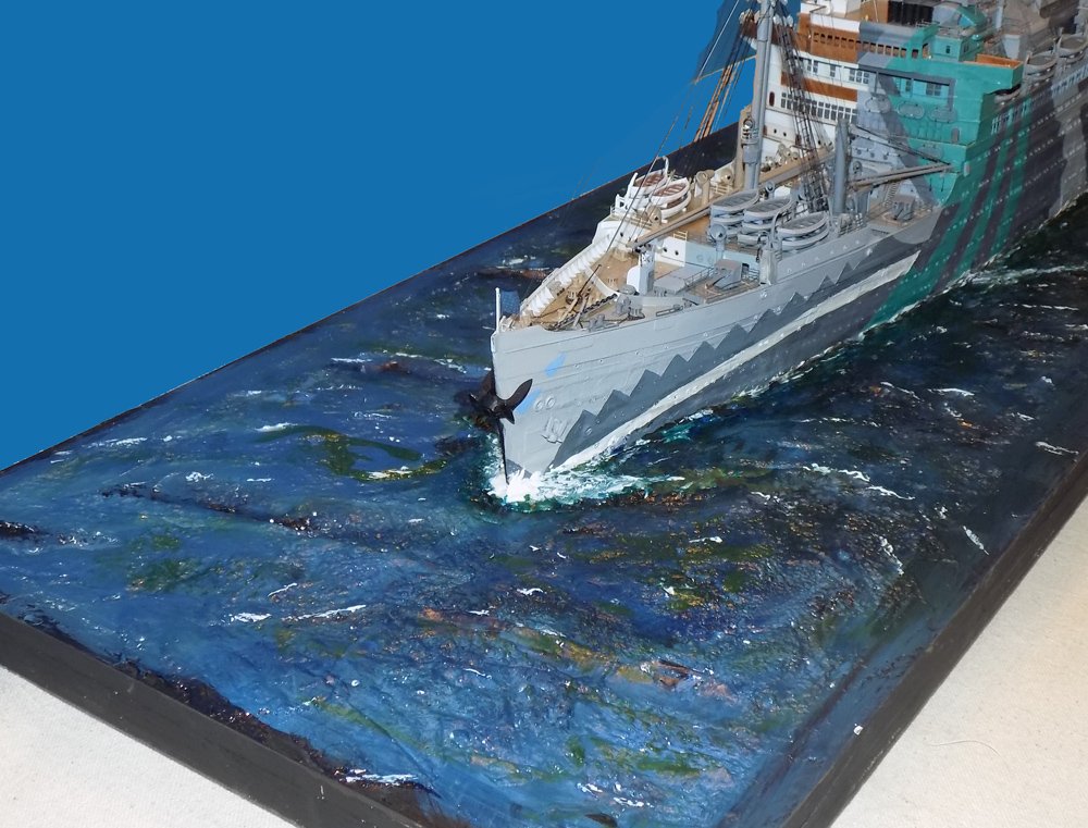
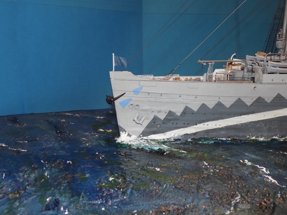
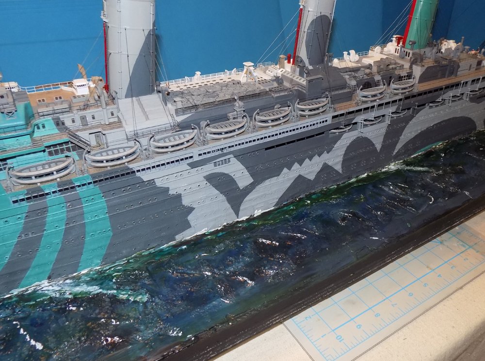
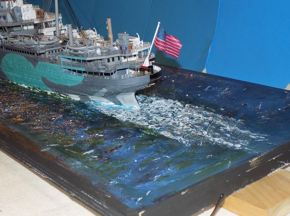
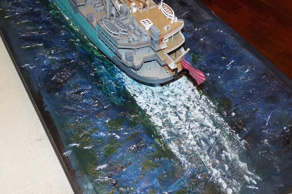
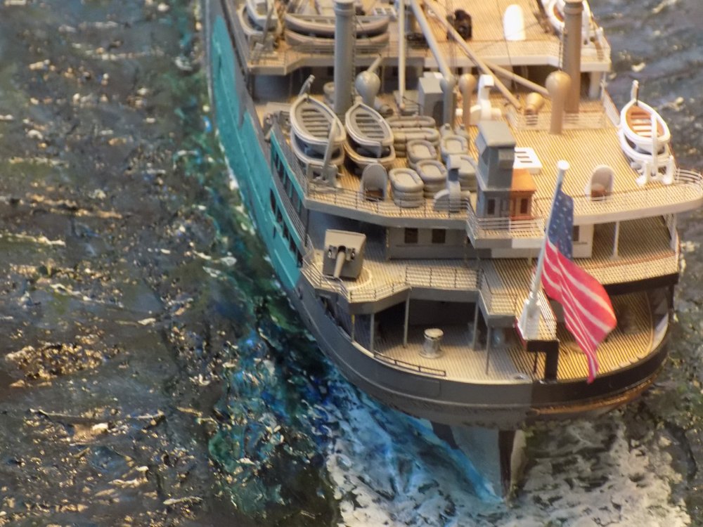
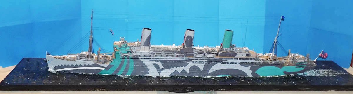
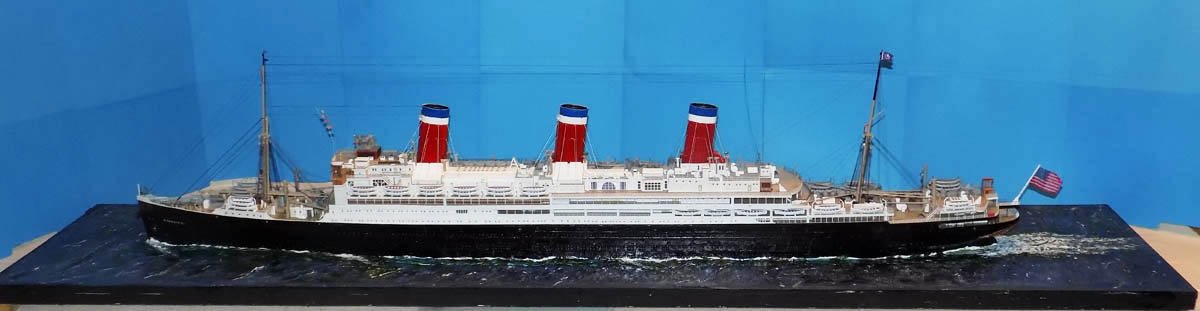
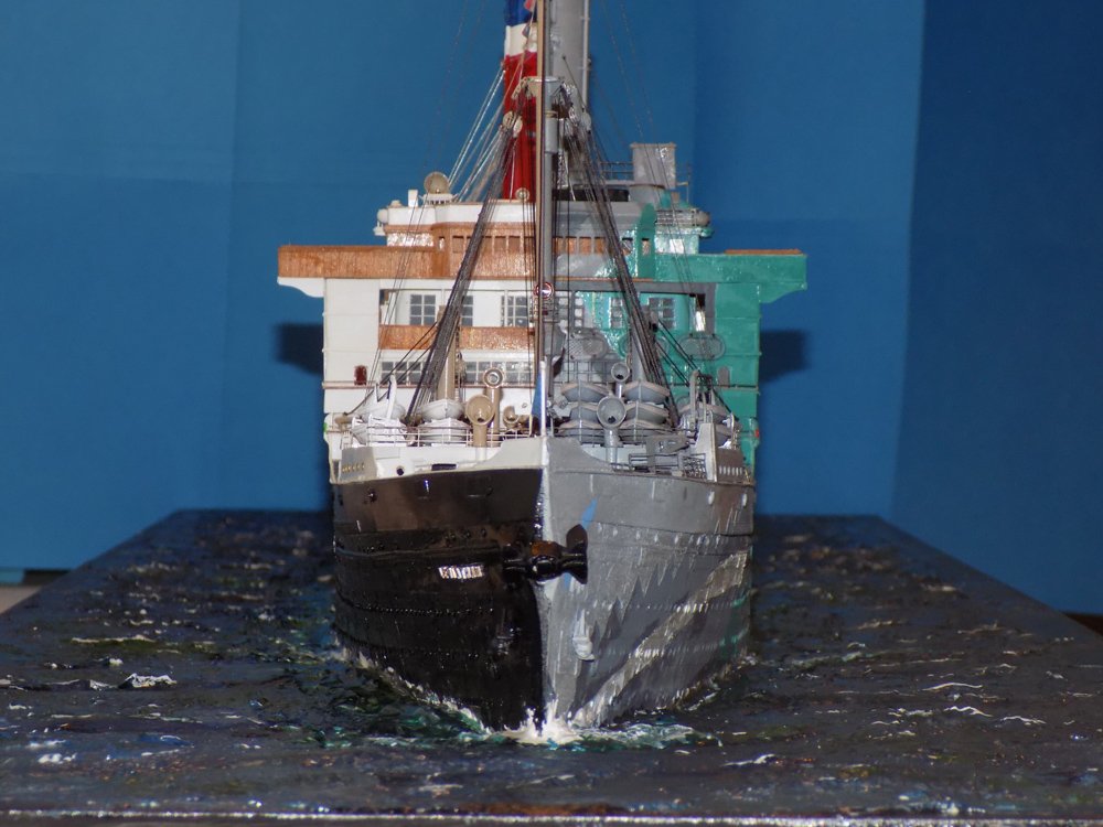
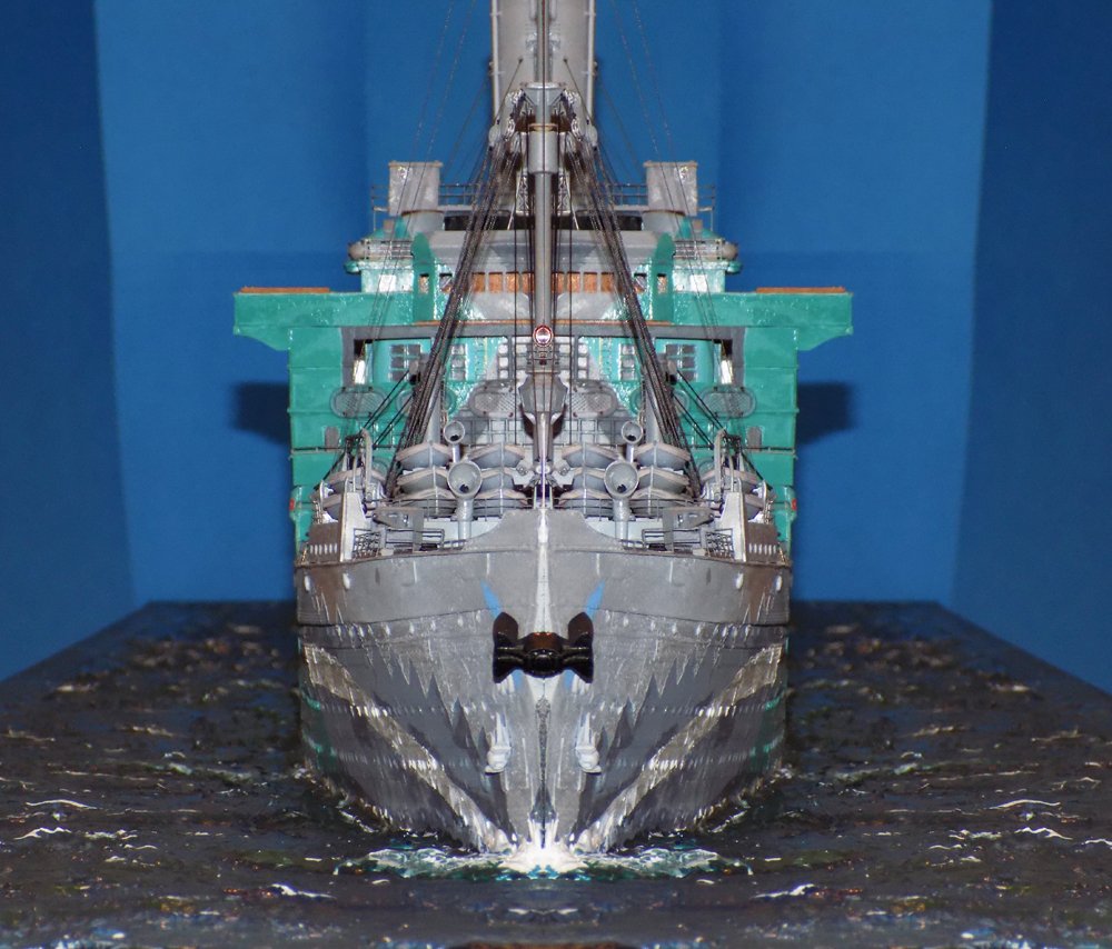
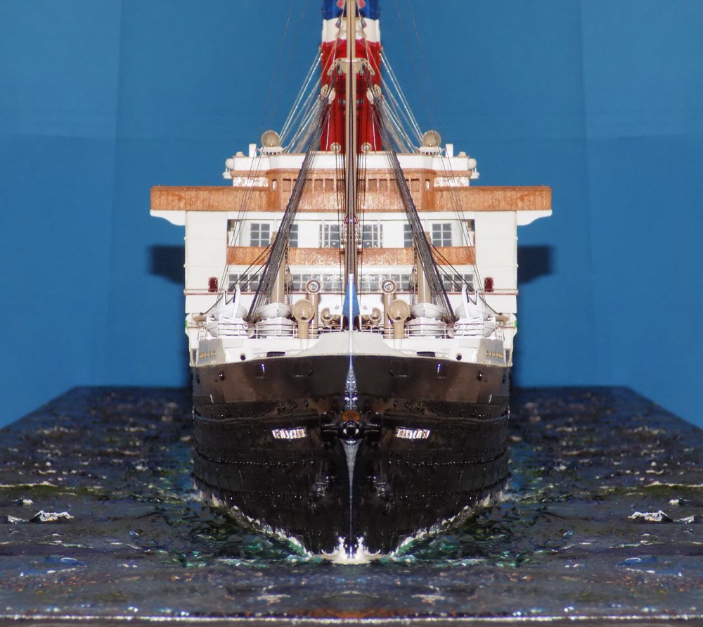
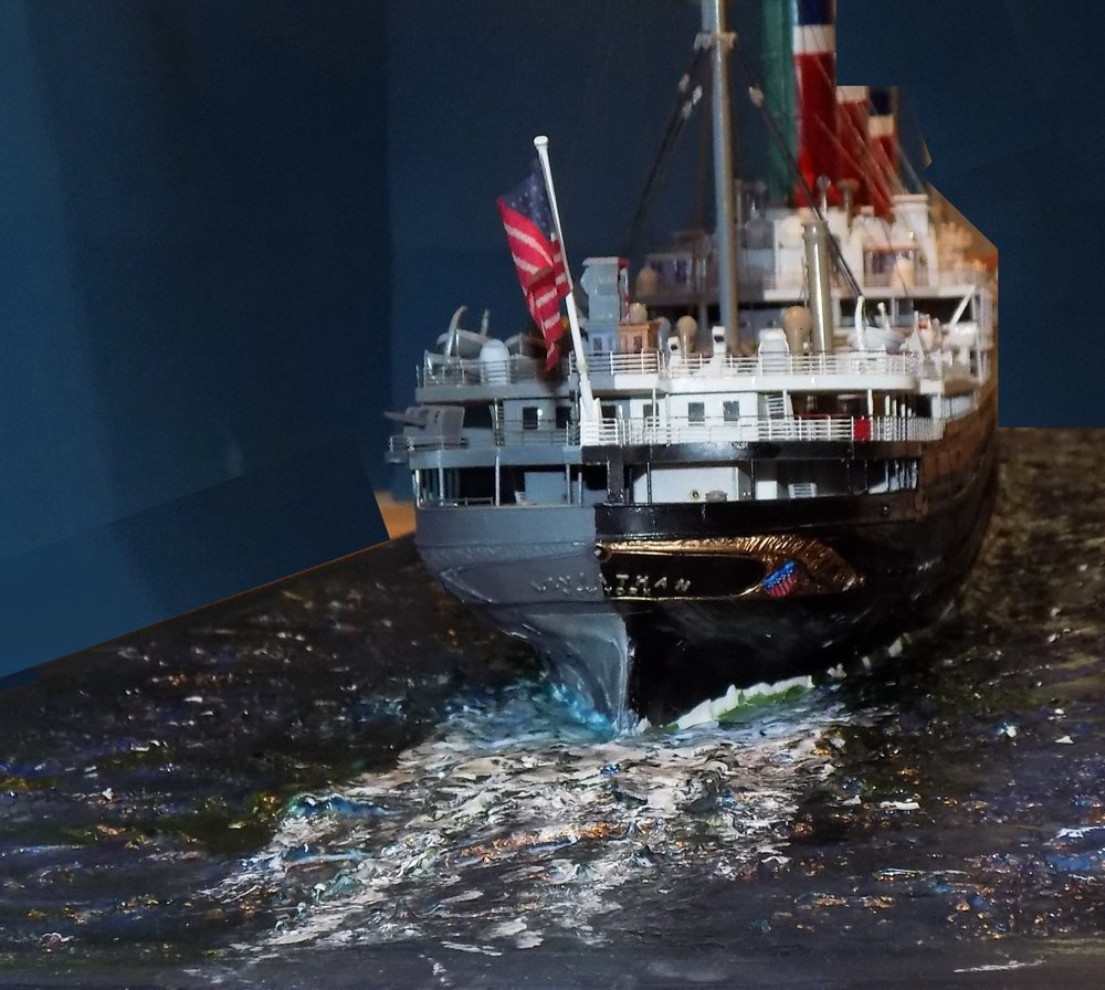
Hi all – and Happy New Year. Thanks as always for the comments and likes. I hope you will enjoy this final installment of the Leviathan build log. With the completion of the model itself, I turned to its display. Under the contract I was asked to set the waterline model in a seascape for exhibition in the museum. Here is how I went about it – The model was located on a board of ¾” furniture grade plywood that allowed about 4 to 6 inches all around. To help show a bit of movement, there was just a bit more space allowed at the stern than at the bow. The model was secured in place with several screws from underneath. Before being screwed down a long strip of kitchen plastic wrap was laid between the model and the board. The excess all around was folded up and lightly taped to the hull to protect it from the plaster sea. Around the perimeter of the board a ¼” lip was created with wooden strips. The space between the lip and the model was filled with premixed vinyl spackle from the hardware store. The tub of product can be seen in the left of the above picture. Three layers were needed to reach the full depth of ¼” since the plaster shrinks a bit and cracks when applied too thickly. The plaster was shaped to illustrate a moderately calm sea. In the middle layer a palette knife was used to impose some swells and waves, but nothing too choppy. The final thin layer of plaster was textured with a damp sponge as it dried to show the random small peaks and valleys of a moving sea. I used a piece cut from a large wallpaper sponge which has a lot more large open holes rather than a denser kitchen sponge. The texturing process was repeated several times until I was satisfied with the results and the plaster layers were fully built up. This process can be continued as many times as desired, and even removed and redone, all without danger to the model itself. When the sea was dry the model was removed, the plastic wrap discarded and the model replaced. Any gaps were filled and the bow wave was laid in with a small spatula. Now the coloring could begin. The first color was straight black, laid into the deepest hollows. Although most were generally parallel, random spots and lines were painted on as well. I took the opportunity to paint the lips and edges as well. Medium blue was painted over the whole surface, followed by dark green. The tops of wave peaks were left white, as was the wake around the ship. These rough colors were tempered by multiple coats of gloss Liquitex medium tinted with color. Dark blue was applied several times, and light green as well. Flat white highlighted crests, and even some deeper foam. These latter were ‘sunk’ into the sea with more transparent layers of blue and green. Along the sides of the ship there was little in the way of wake, the ship moving slowly as it approached harbor. There were some diagonal wakes shown where the pressure waves would have impacted the hull, but these were severely muted with green tinted gloss. Similarly, the water alongside the hull was lightened to show its disturbance by the ship’s passage. At the stern the chop from the four propellers was mottled with white, stippled with a dry brush and, again, toned down and ‘sunk’ with tinted glaze. The beauty of this method is that the colors and tints, and even the white highlights, can be altered and adjusted almost indefinitely until the desired shape, color, tint and reflectance is reached. With so many transparent and translucent layers, the water looks deep and changes hue with changes in light and viewing angles, just like the real sea. So here she is. Finished. The troop ship, port side. And the ocean liner with the photo reversed to show the same port side. The model’s bow showing the contrasting presentations. And the photo cropped and mirrored to show how each might have been seen as a whole ship. So now I bid a fond farewell as she sails off to her permanent home in the museum of the American Merchant Marine Academy at King’s Point, NY, on the shores of Long Island Sound. If you can, it is well worth a trip to this wonderful little museum. You can also book a tour of the school where you can view many more excellent models and even take the helm in a bridge simulator. Meanwhile, I have been working on the next project for the museum. It is a Great Lakes whaleback steamer called the SS James B. Colgate. It was a bulk grain and ore carrier launched in 1892 and sunk in a storm in 1916. I will post photos soon. Till then, thanks for following along. Be well. Dan
- 238 replies
-
- 23
-
-
- leviathan
- troop ship
- (and 2 more)
-
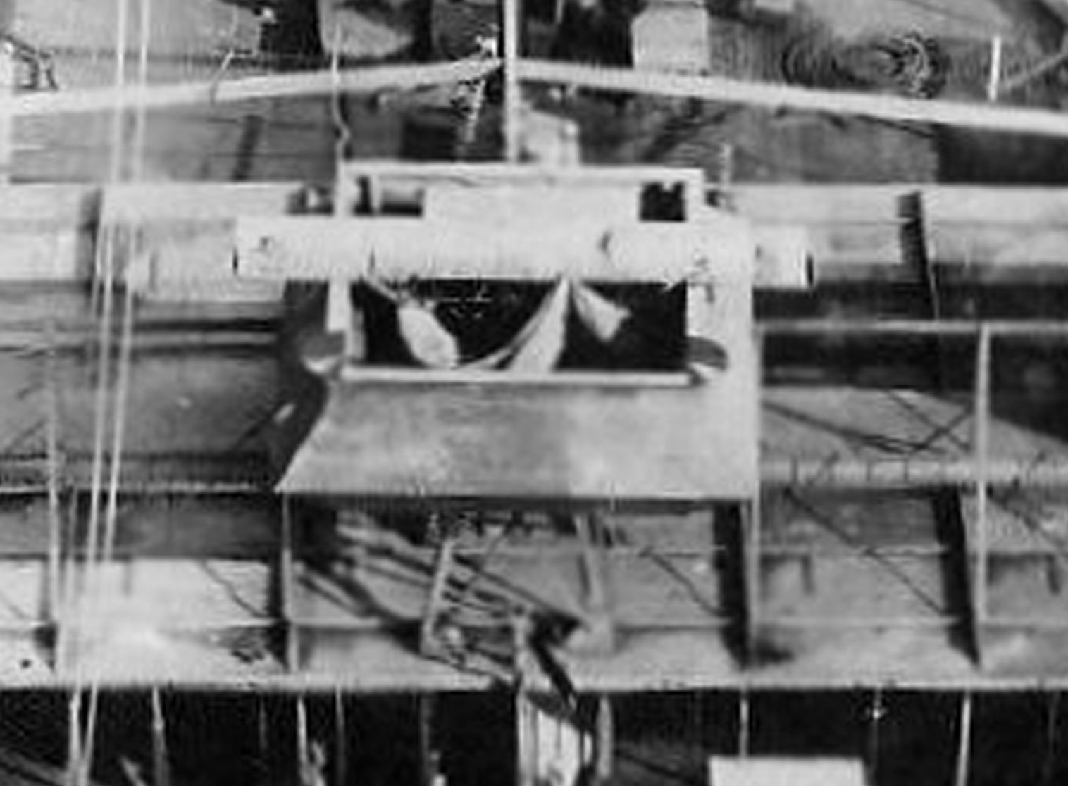
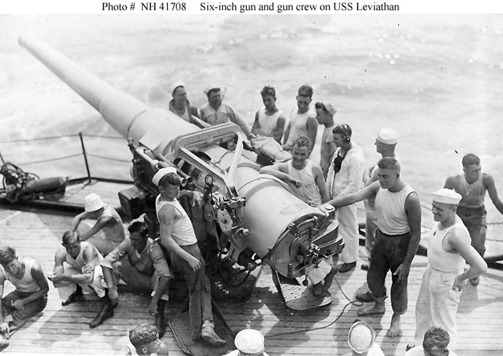
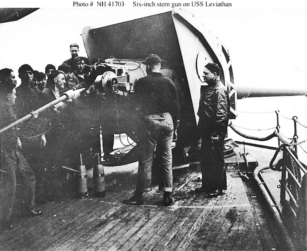
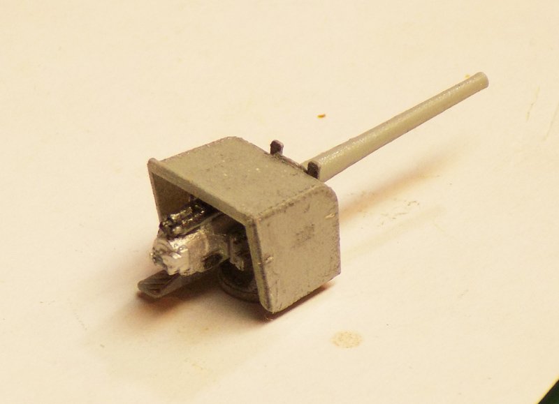
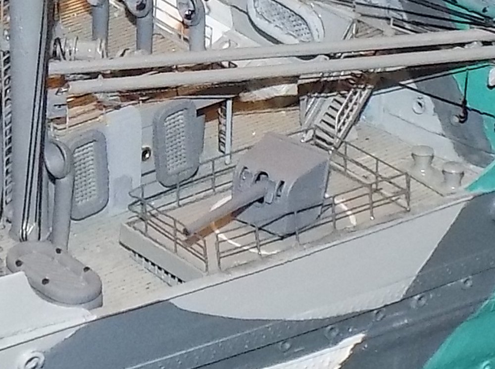
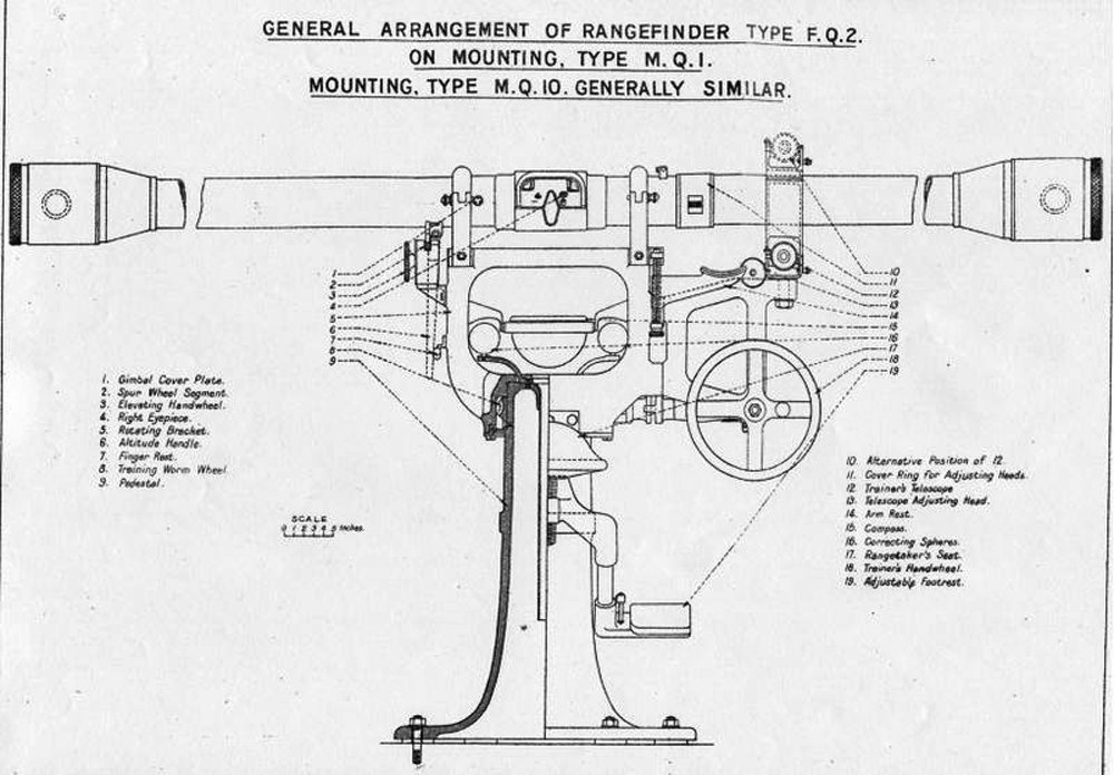
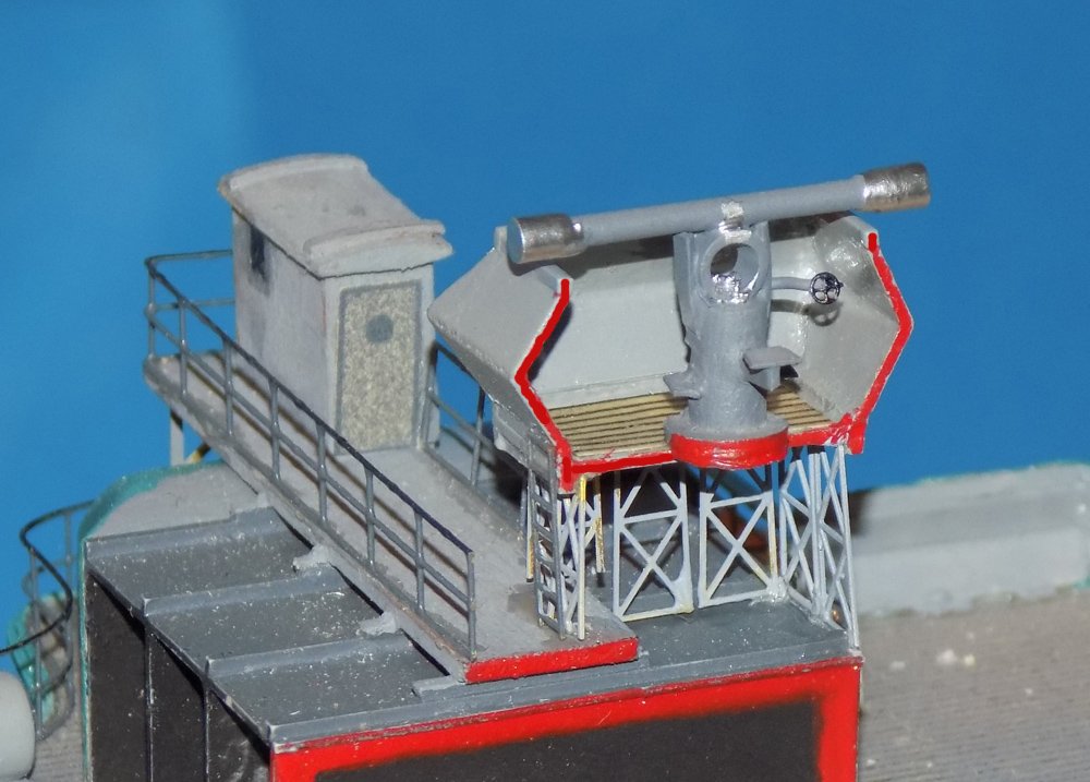
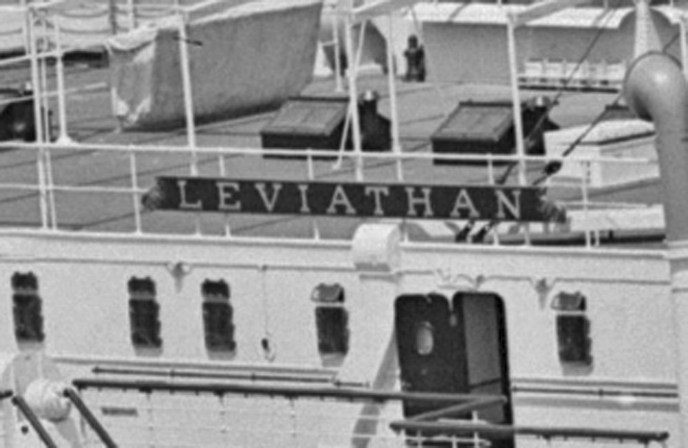
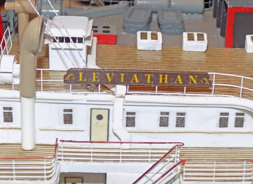
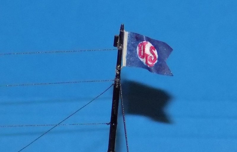
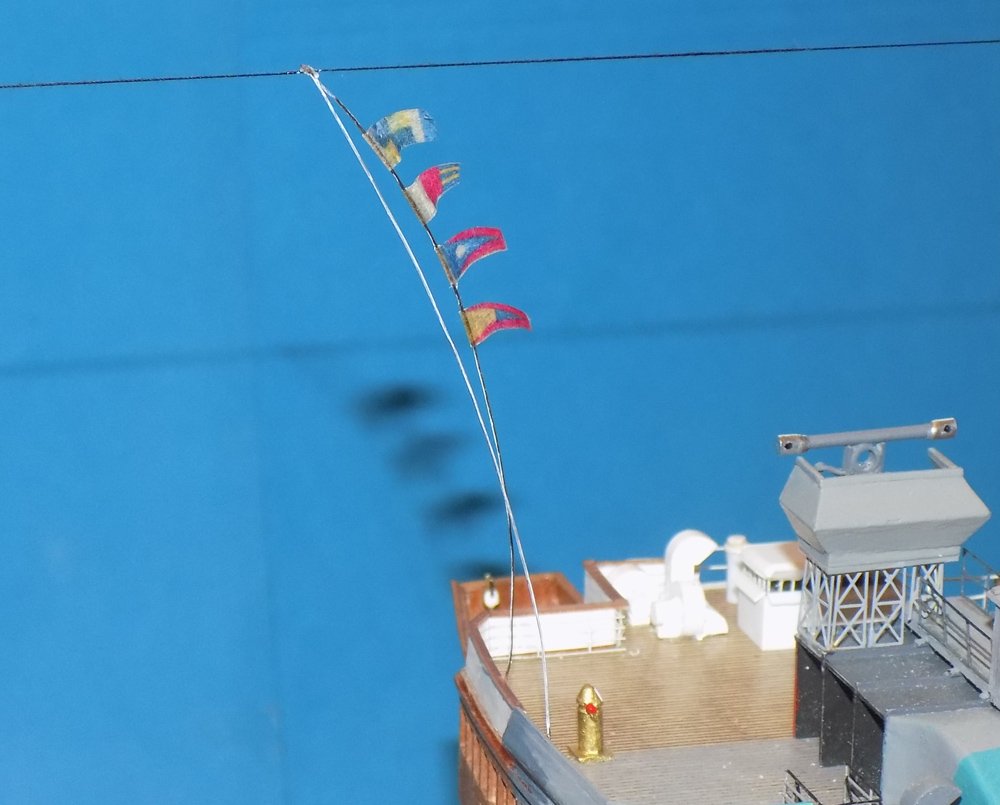
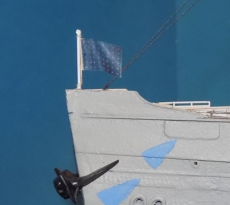
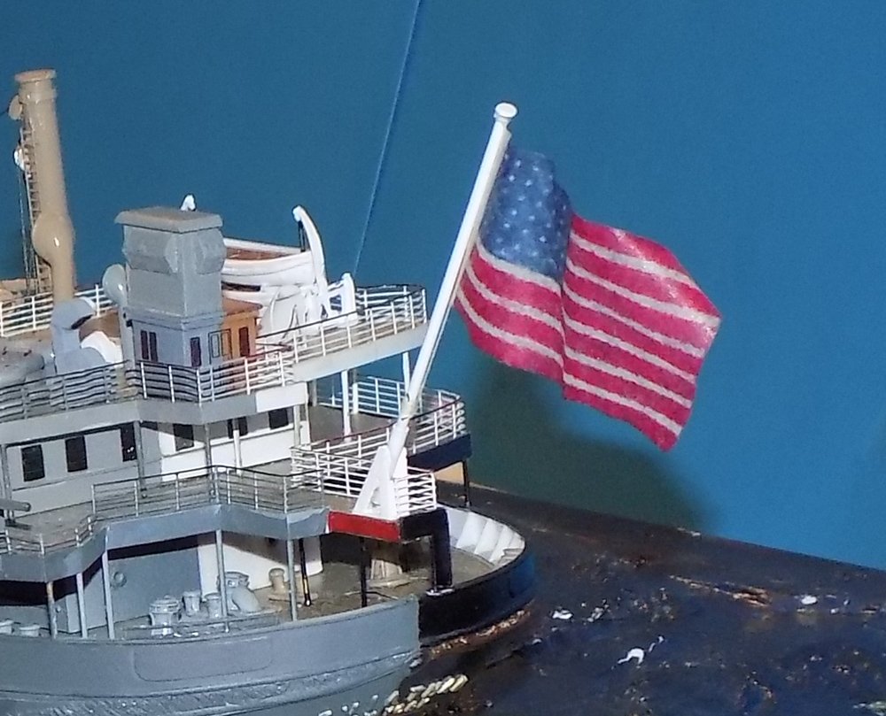
Thanks, everyone, as always. One of the best things about our community is all the support we give each other. Here are the finishing details for the ship. First, the 6 inch cannon. The 3-D printed ones from Shapeways are little gems and match quite closely the photos. On top of the flying bridge a square platform was built with angled sides. The history of the ship identifies it as the large rangefinder for the guns. This is the best photo, taken during the conversion to the troop ship. I believe that the long thin box on top was a wooden cover for the rangefinder, but I have no definitive proof. I did manage to locate a schematic for a contemporary rangefinder of the size that would fit the platform and which is just tall enough to rise above the platform sides. And here is how it came out on the model. I am not sure about the metallic ends, but I reasoned that paint might interfere with its operations, and when not in use the wooden cover would hide them. I cheated a bit by giving the rangefinder a complete base and pedestal rather than cutting it in half. As before, the red edges indicate that the structures were cut along the centerline. On the liner side the bridge deckhouse sported a wooden nameboard. It was computer printed on acid free art paper. The model sports several flags. This is the house flag of the United States Lines from 1929 The signal halyard bears the flags of its radio call sign, LHGD (thanks for this information go out to Richard Rabbett) They are mounted on a wire halyard that is bent as if by the wind. At the bow is the US ensign with 48 stars. Although this would not normally be flown at sea, I am picturing her moving 'slow ahead' and entering New York harbor. And at the stern the Stars and Stripes. This completed the model. Next, making the ocean, and final photos. A Healthy and Happy Holiday to one and all. Dan

- 238 replies
-
- 10
-
-
- leviathan
- troop ship
- (and 2 more)
-
Hi Michael - Yes, the stern windows will be an interesting artistic element for Marc. I'm looking forward to seeing how he decides. My mother, who was an American antiquities expert, once did a study of pre-colonial (around 1750) glass. If I recall her results, it was that most glass, except really low end stuff, was pretty clear and flat when made, But the composition of the glass meant that it would sag fairly quickly, which is what we see and value now. But I imagine that the windows of the Admiral's quarters would have been glazed with top quality glass So I would go with high gloss panes, initially. If they are too glaring, then satin/eggshell touch-up. Just one possible way to go. Dan
- 2,699 replies
-
- 4
-
-
- heller
- soleil royal
- (and 9 more)
-
Hi Toni - Looks like another interesting project, and the finished model is certainly quite beautiful. I have done a number of lapstrake hulls, and I would not want to fiddle with fairing the overlaps while also worrying about the dead space between bulkheads. I would fill at least one more space at the bow and two at the stern. That should make the fairing process a bit easier. Hope that helps. Dan
-
Keith - Beautiful metalwork. I am green with envy. How do you keep the deck plates from flying into Neverland when you part them off? I would be hunting them for days. Dan
-
Thanks, guys, for the compliments and likes. Sorry I'm not giving a more complete explanation, but the techniques are pretty much the same as explained previously. I'll go into a bit more detail when I get to making the ocean display base. Keith - the blocks and winches are from Bluejacket. Everything else is scratch-built. More soon Dan
- 238 replies
-
- 6
-
-
- leviathan
- troop ship
- (and 2 more)
-
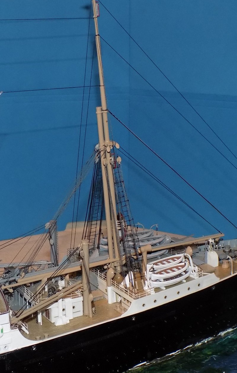
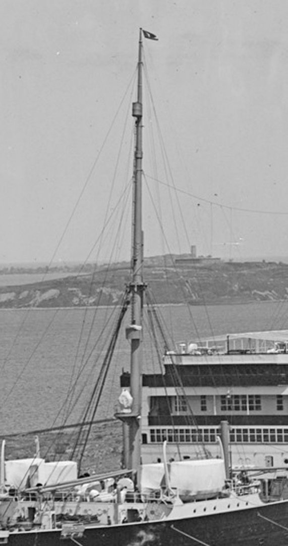
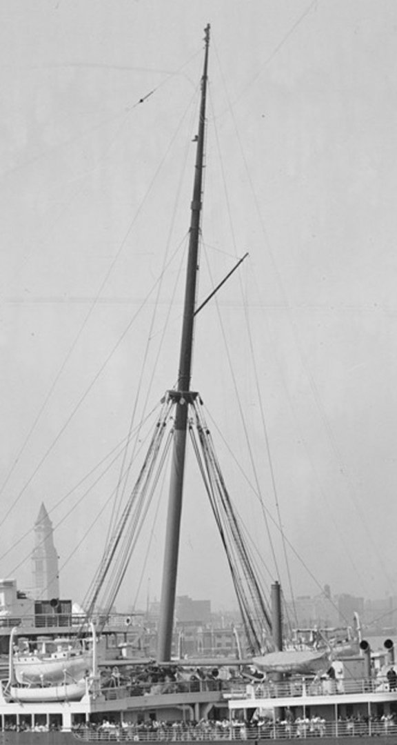
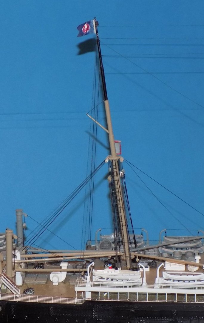
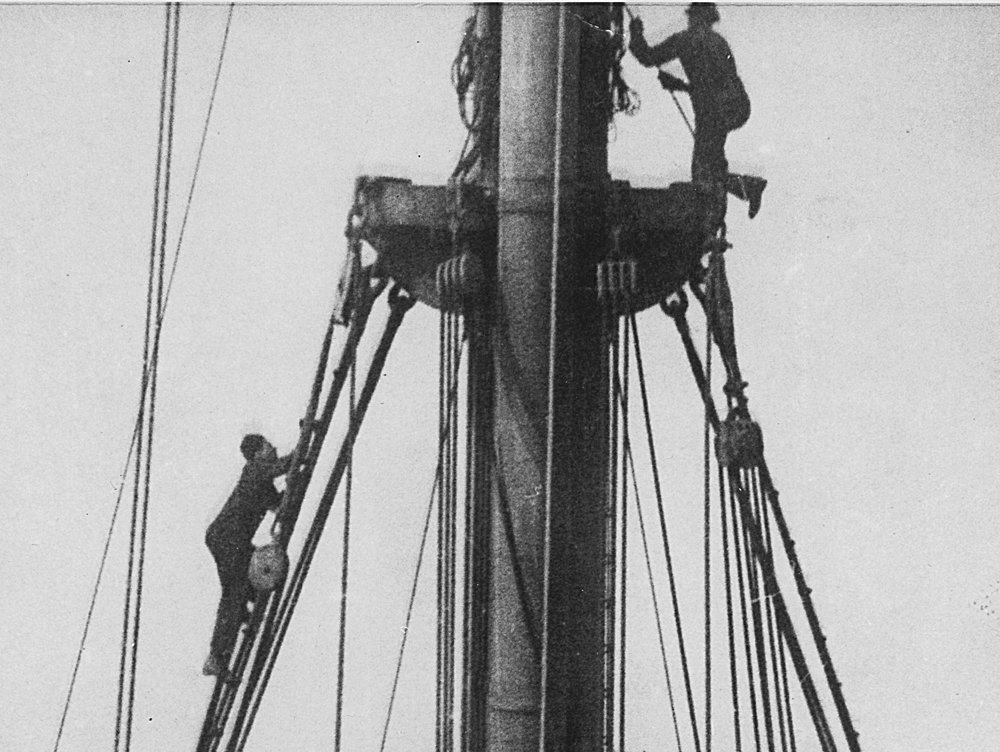
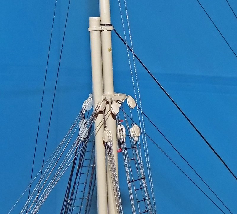
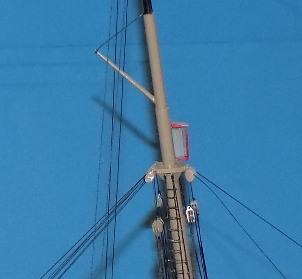
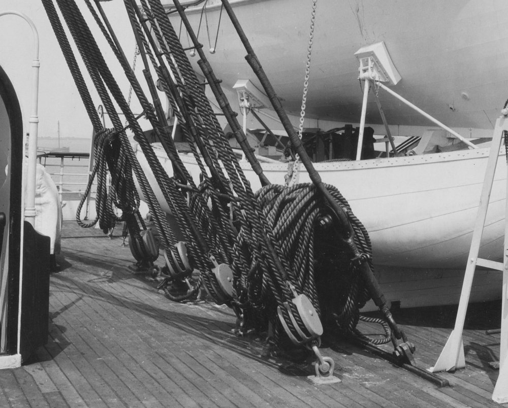
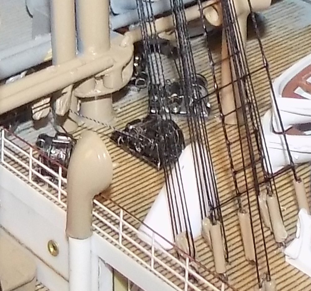
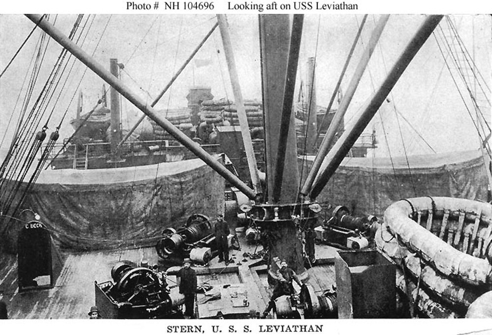
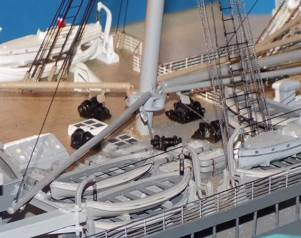
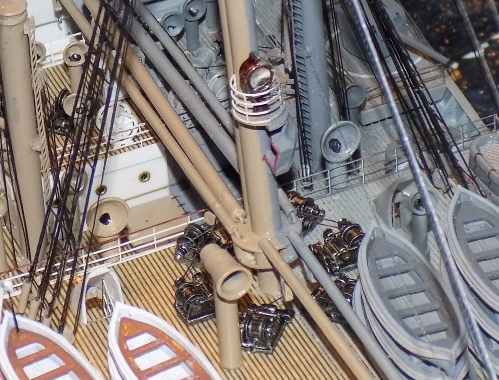
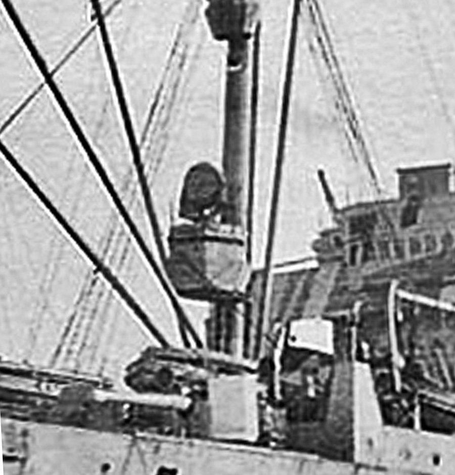
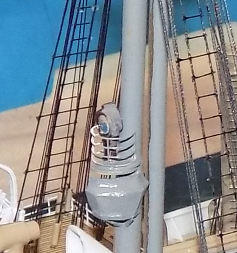
Hi all – I hope my countrymen all had a good Thanksgiving and everyone's favorite football team, whether round or oval, won. Unfortunately, I root for the NY Giants. Oh well . . . Here is the next segment of the build. As before, mostly photos with captions. The final major components of the ship were the masts, which also acted as the cranes for the cargo booms. Here they are in photographs. And how they turned out. The mast tops anchored the shrouds and stays, and the single and triple blocks of the boom tackle were secured here as well. I could not fit any available triple blocks for the topping lift tackle so I used doubles. The lift tackles reeve through double blocks at the deck just inboard of the shroud turnbuckles. There are four shrouds, with ratlines only between the inner two, though there are swifters every fourth ratline that go across all four. The bases of the booms have clevis joints that fit in a ring around the base of the mast. There is a multi-headed steam winch for each boom, set in a circle on deck around the mast. A large searchlight sits on a railed platform on the foremast. On the troop ship a large lookout station was hung below the searchlight. Its peculiar shape had to be pieced together from segments of plastic tube turned inside out. The final few details to finish the ship will be covered in the next installment. Till then, be well. Dan

- 238 replies
-
- 14
-
-
- leviathan
- troop ship
- (and 2 more)
-
Hi Marc - If you can make it to the club meeting this coming Tuesday I can show you how I make molding scrapers from used hobby blades. Just another suggestion among several others that work. Dan
- 2,699 replies
-
- 3
-
-
- heller
- soleil royal
- (and 9 more)
-
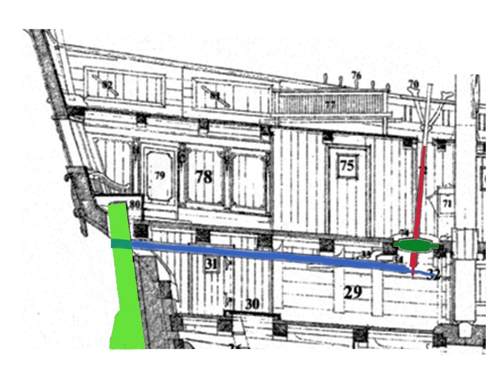
Hi Marc . . . and Marc - I believe that the rudder hole was rectangular because the tiller (in blue) went through it, not the rudder. The tiller, in turn, was connected to the whipstaff (in red) that pivoted through a rowell or rowl (in green) Here the rudder head is housed in a closed off box, but many that I have seen end just above the tiller and below the counter. This from an illustration by Phillips from around 1690. I'm sorry but I have misplaced the full information on the illustration. Dan
- 2,699 replies
-
- 5
-
-
- heller
- soleil royal
- (and 9 more)
-
You're more than welcome. If I can manipulate any other images for you, let me know. And that's spelled GEE-zer. LOL Dan
- 2,699 replies
-
- 4
-
-
- heller
- soleil royal
- (and 9 more)
-
I cobbled this together and I think I see what you mean. So, as they say - 'Yer pays yer money and yer takes yer choise"
- 2,699 replies
-
- 5
-
-
- heller
- soleil royal
- (and 9 more)
-
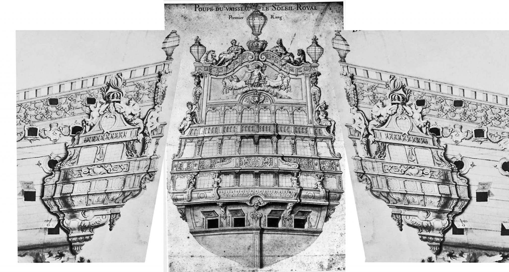
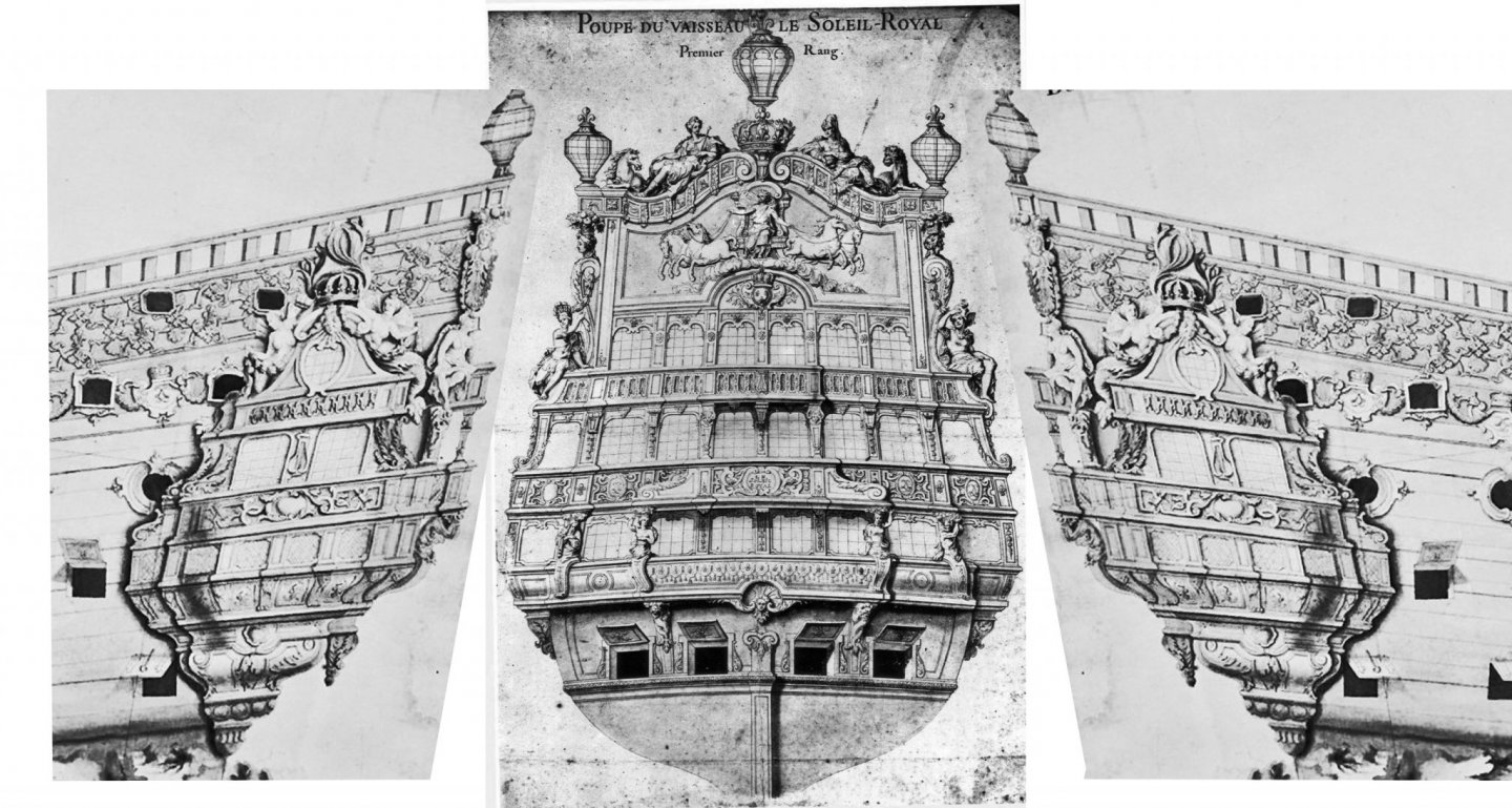
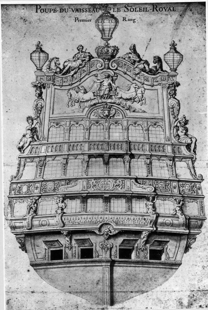
Marc - Yes, I think the upper balcony is only two bays wide, judging from this drawing. It also looks to me that the middle balcony is two bays wide, with decorative extensions to shade the 4-bay lower balcony. Is that how you see it? Dan
- 2,699 replies
-
- 3
-
-
- heller
- soleil royal
- (and 9 more)
-
Hi Marc - Fascinating in depth discussion, as always. To help me see what you were saying, I took the drawing and enhanced the contrast with Photoshop It really made the shadows pop out.
- 2,699 replies
-
- 6
-
-
- heller
- soleil royal
- (and 9 more)
-
Hi Marc - Have you considered laying on a plastic mesh over a flat clear plastic? Turn it 45 degrees for a diamond pattern like Tanneron's. Here is one possible mesh from Amazon - it is 4" x 4" and has 28 x 28 cells, or 7 cells per inch. https://www.amazon.com/Darice-10-Piece-Square-Plastic-Canvas/dp/B0018N29Z2/ref=sr_1_5?keywords=plastic+mesh&qid=1574305574&sr=8-5 10 pieces for $2.25 if you are being frugal. I don't know if this mesh is fine enough, but there were lots of others. And if you continue as you have begun, this will be a silk purse fit for Marie Antoinette. Dan
- 2,699 replies
-
- 3
-
-
- heller
- soleil royal
- (and 9 more)
-
Roger - Thanks so much. I will use the model to check against mine and the photographs that I have collected. I will do a brief boat tour log once I have finished. Dan
- 238 replies
-
- 2
-
-
- leviathan
- troop ship
- (and 2 more)
-
First, thanks to everyone for the compliments and likes. Roger - a special thanks to you. Photos of another model will be very welcome. I am still trying to piece together from photographs the exact details of the stern deckhouse and its roof. Dan
- 238 replies
-
- 1
-
-
- leviathan
- troop ship
- (and 2 more)