shipmodel
-
Posts
941 -
Joined
-
Last visited
Content Type
Profiles
Forums
Gallery
Events
Everything posted by shipmodel
-
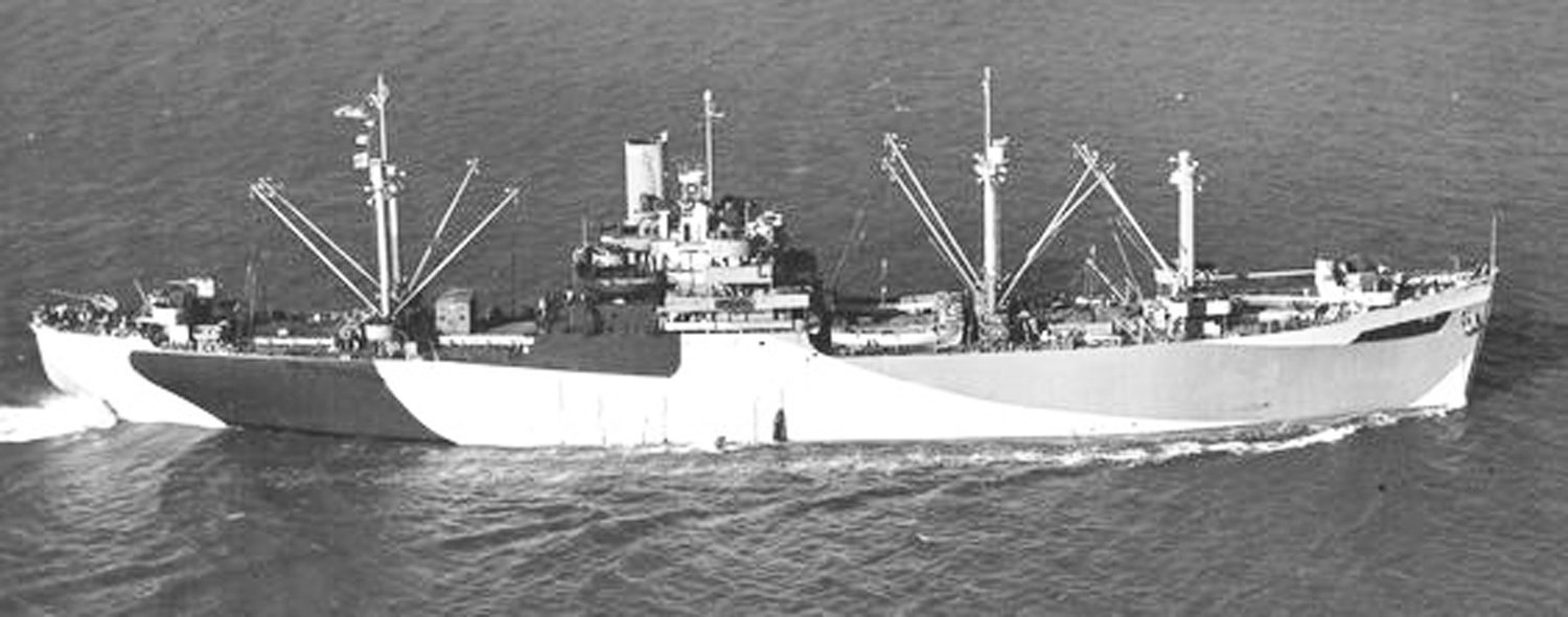
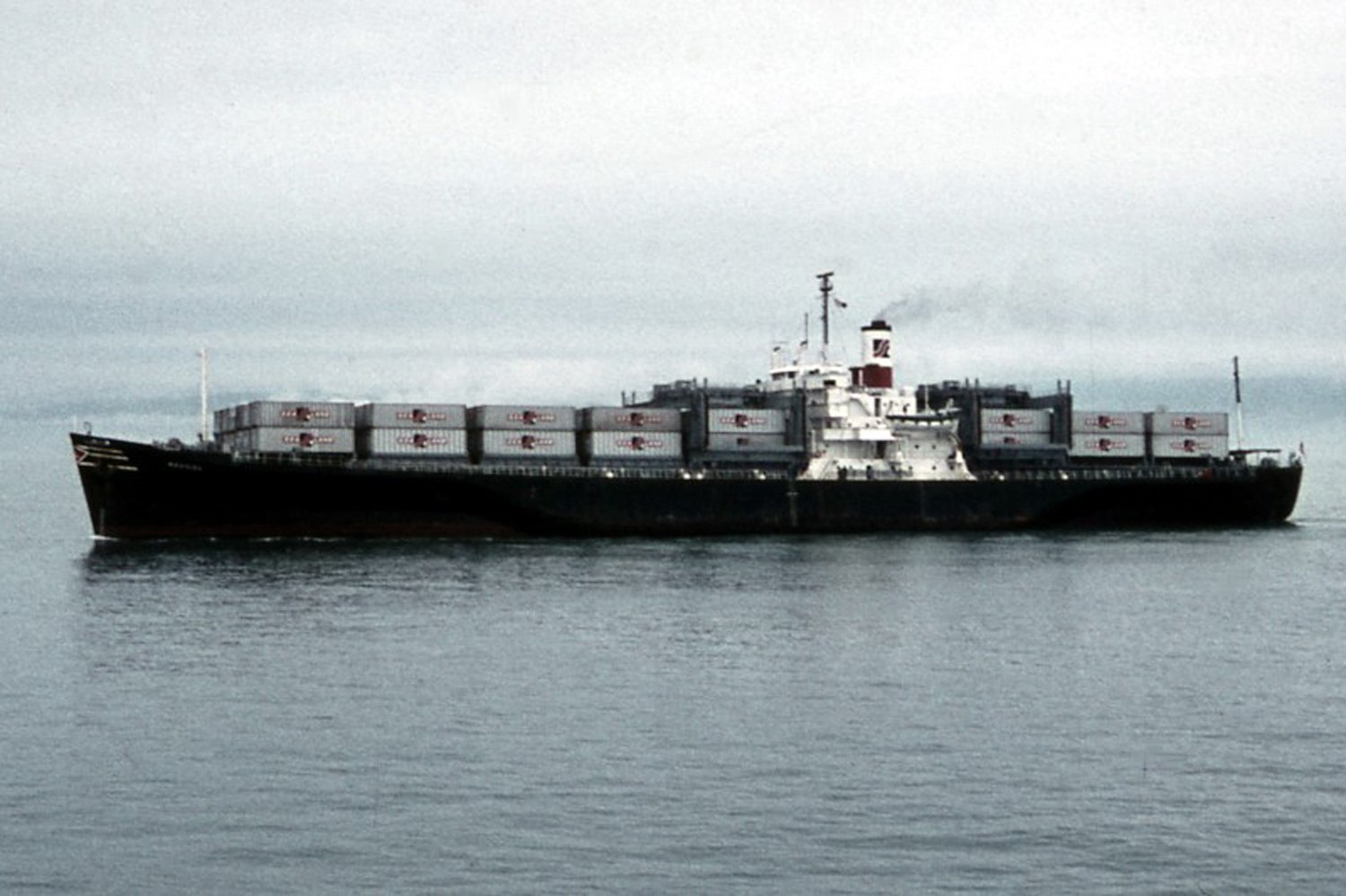
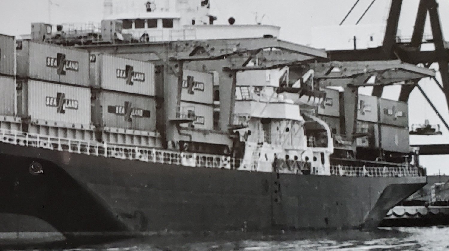
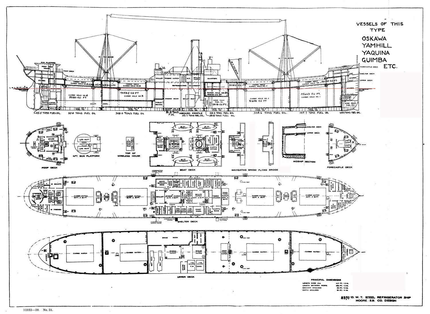
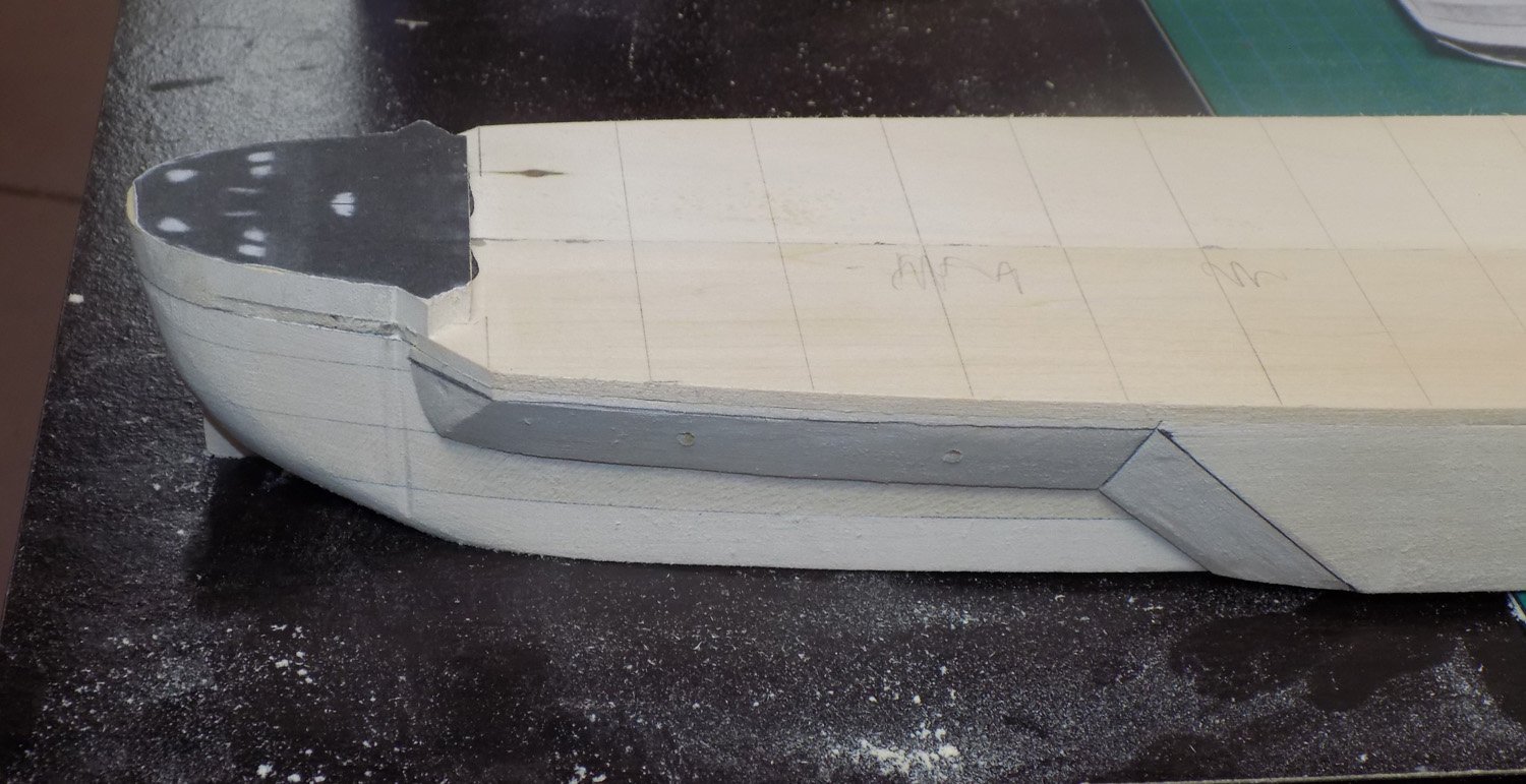
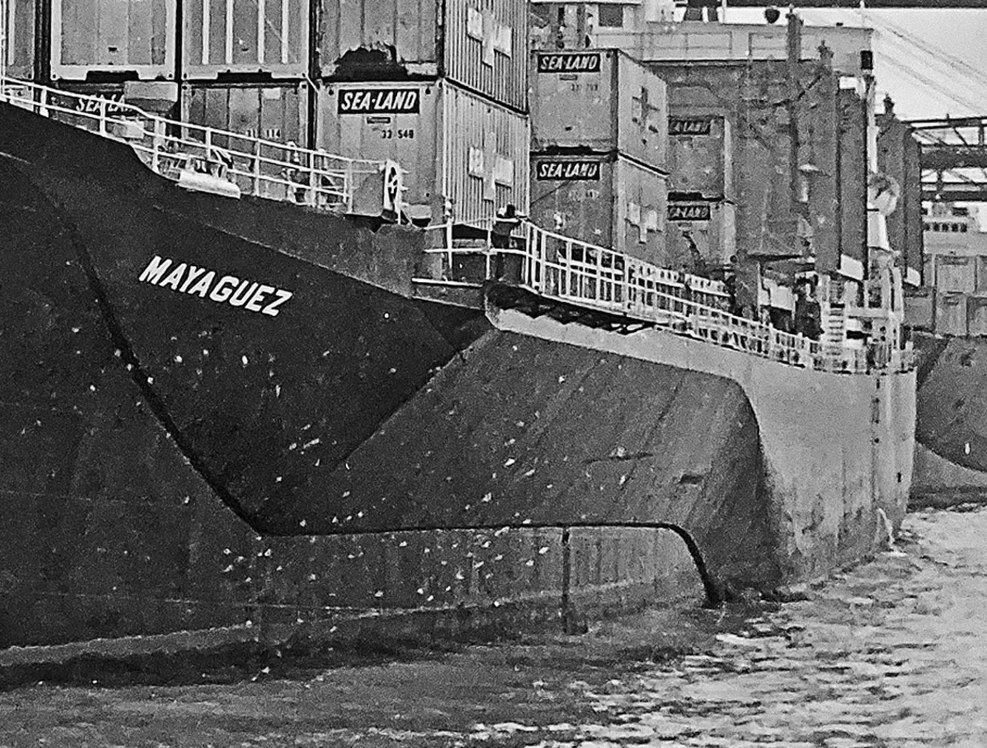
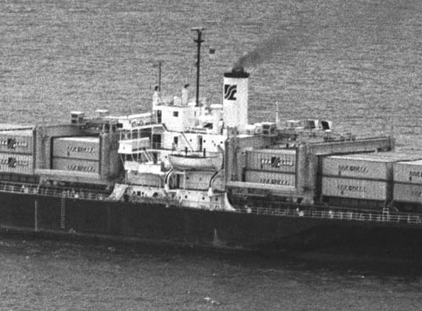
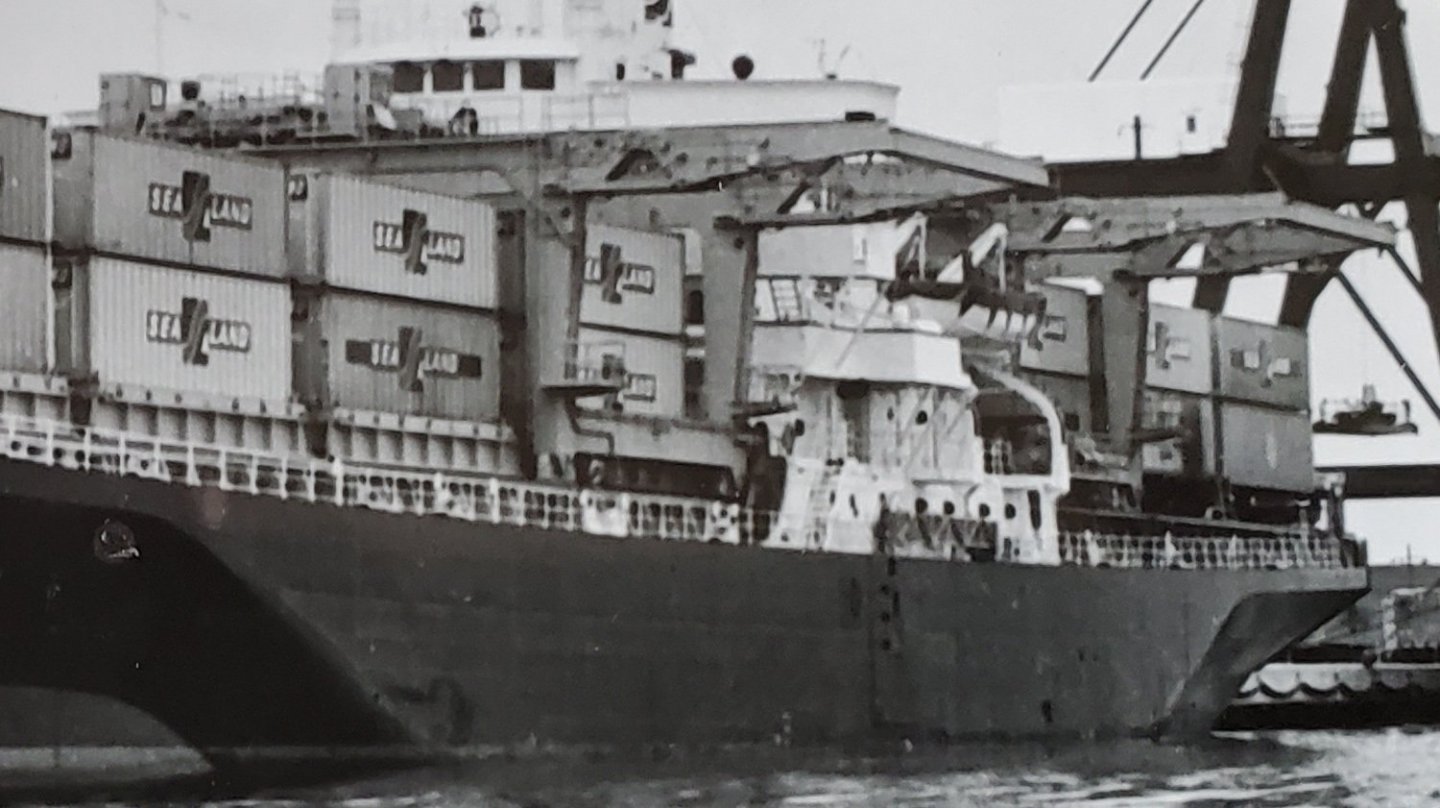
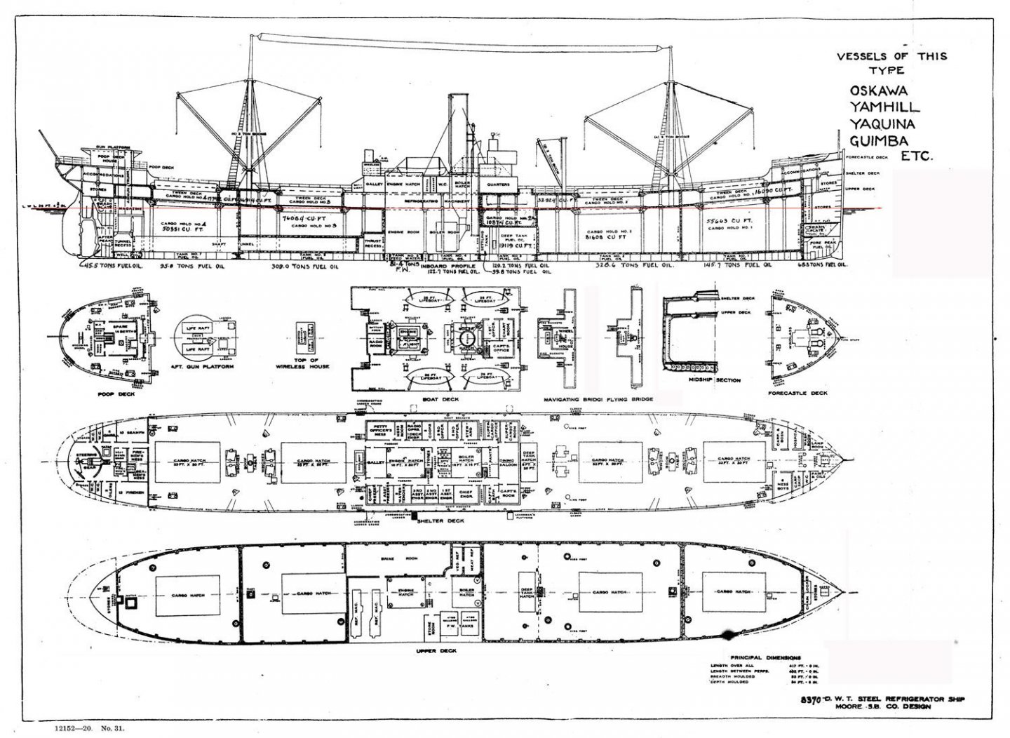
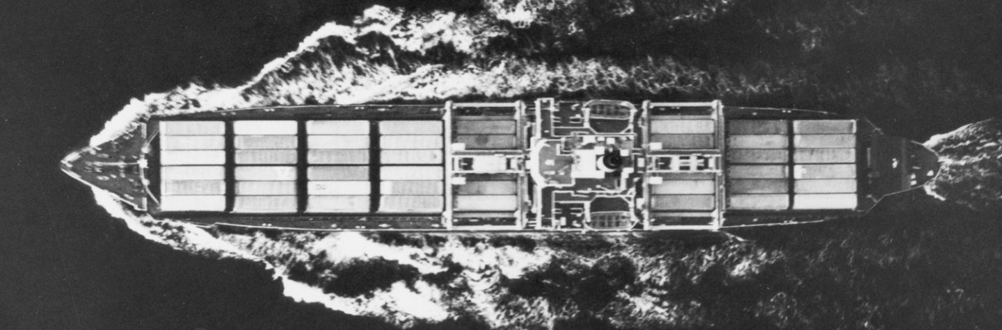
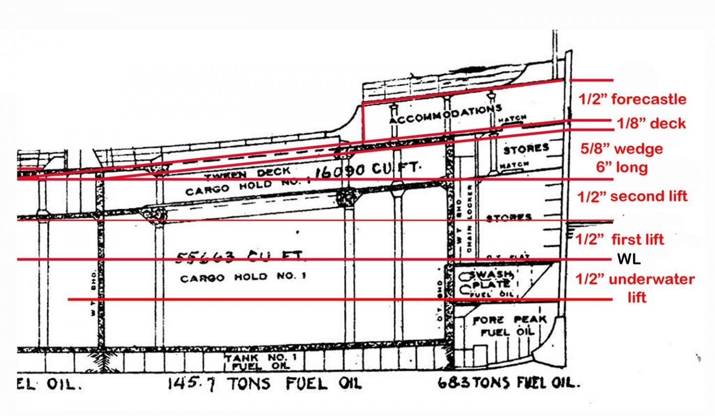
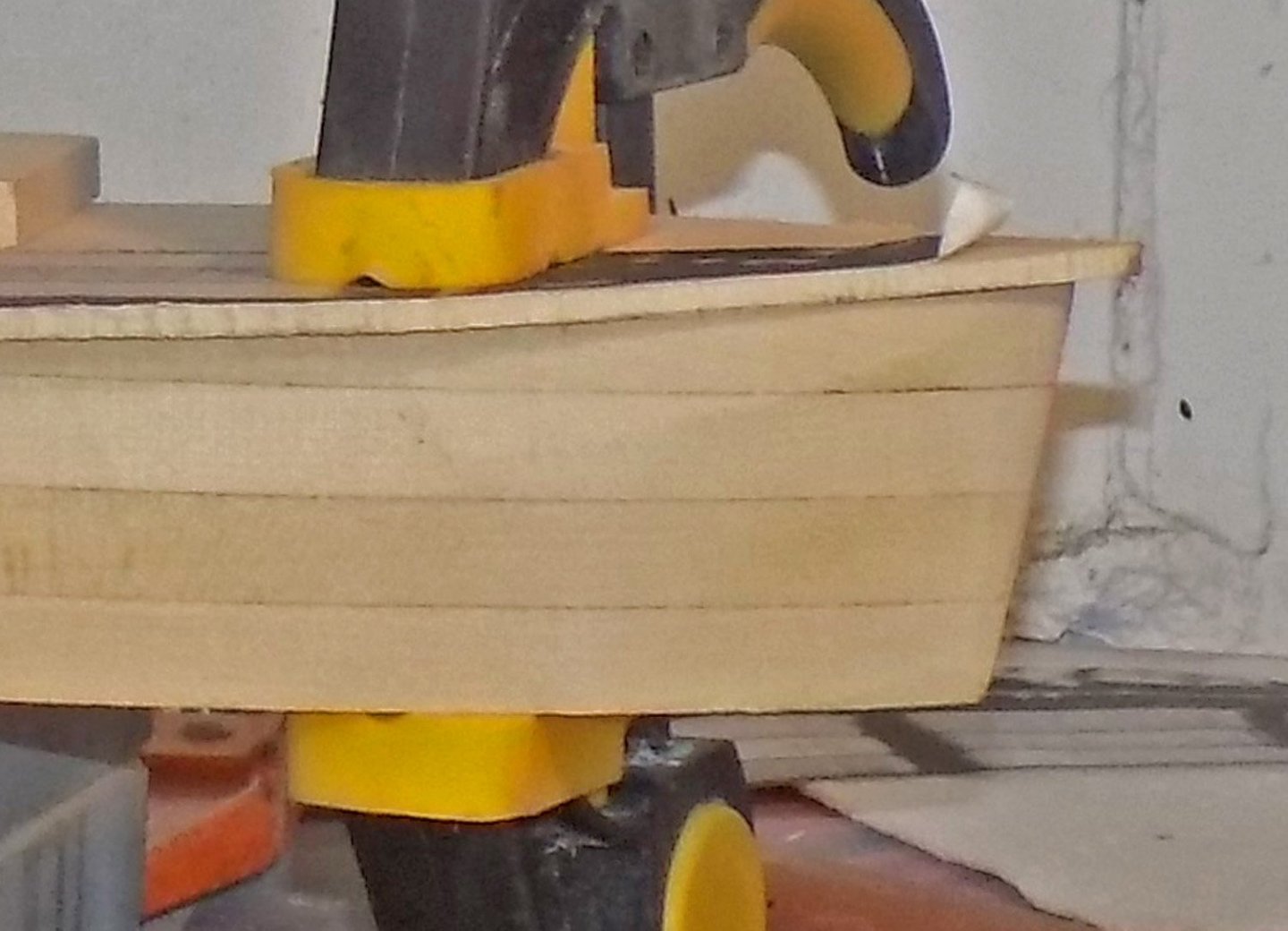
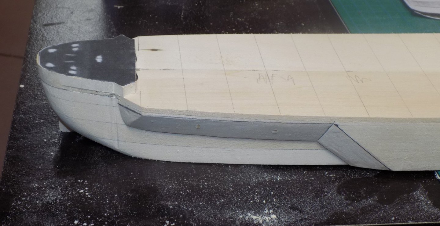
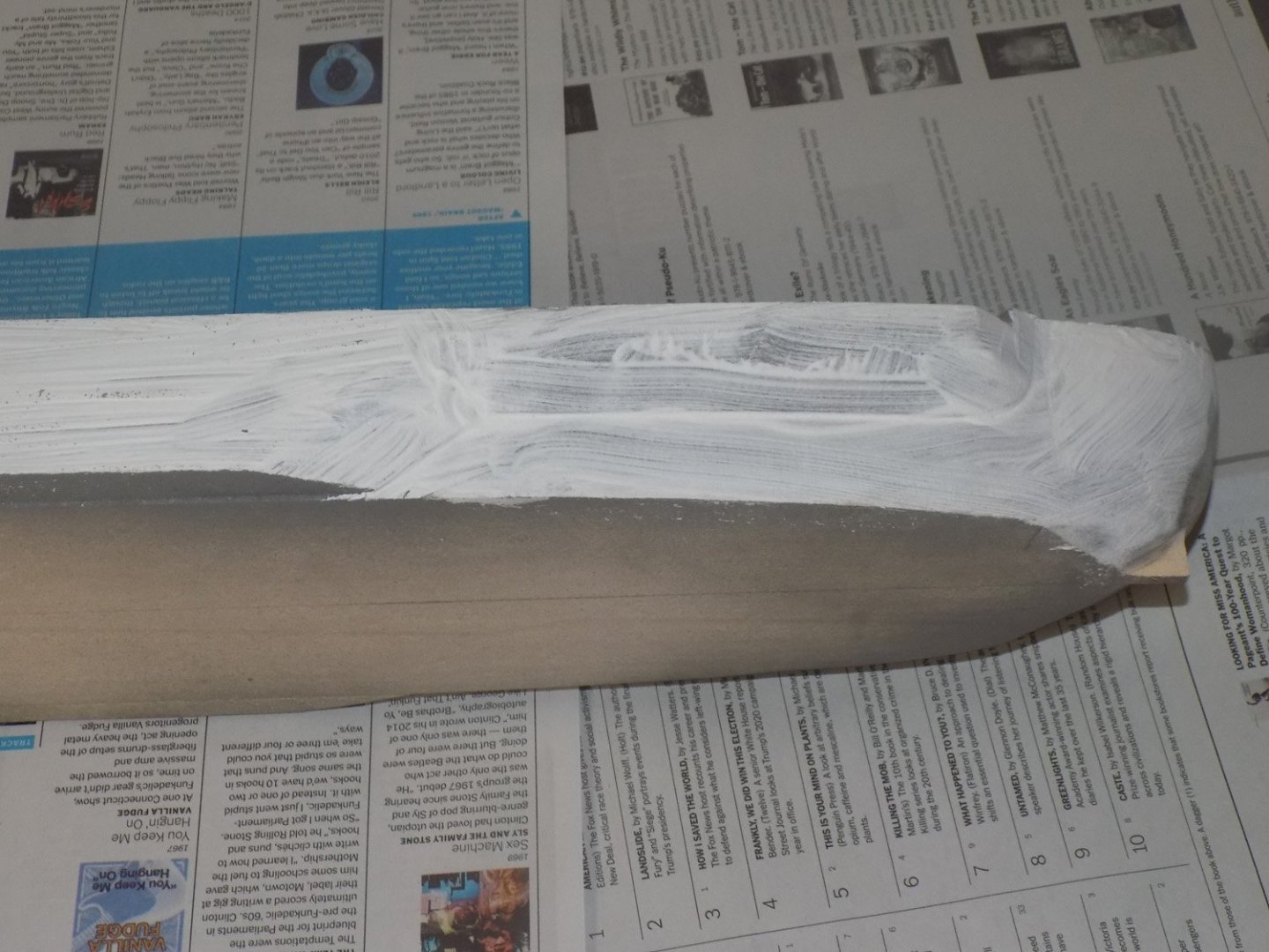
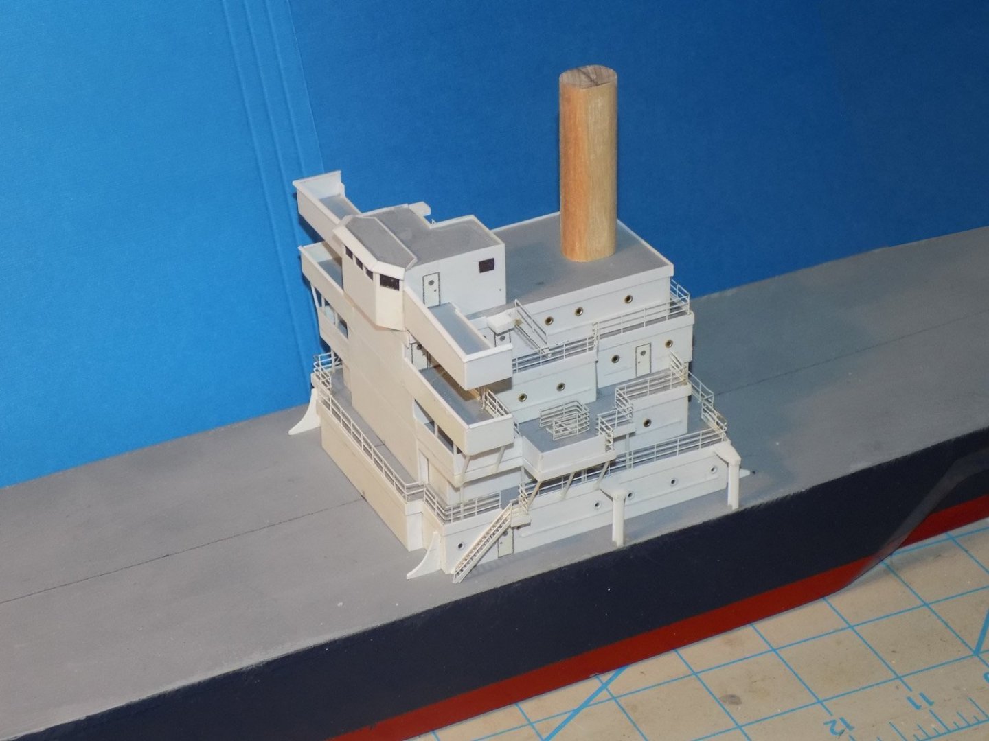
 SS Mayaguez (c. 1975), scale 1:192 by Dan Pariser Hi to everyone who followed me from the build log of the restoration of the bone and ivory POW model to this one, and hello to any modeler who might be interested in a completely different subject using completely different materials. I hope that I can make this build log as informative as the last one. The subject here is the SS Mayaguez, an American container ship that was involved in a famous incident of piracy at sea. On May 12, 1975, about a week after the fall of Saigon, and a month after the fall of Cambodia (renamed Kampuchea) to the communist Khmer Rouge, Mayaguez was en route from Hong Kong on what was to be a routine voyage. Travelling through a disputed area, the ship was accosted by a gunboat flying a red flag which fired machine guns and a rocket over the bow. The ship stopped and was taken over by Kampuchean sailors. The crew were captured and removed from the ship. Upon learning of this, American planes were scrambled from nearby bases and photographs of the ship and gunboats were taken as hurried plans were made to recapture the ship and free the crew. SS Mayaguez was launched in April 1944 as SS White Falcon, a Maritime Commission C2-S-AJ1 freighter built in North Carolina. Type C2 ships were all-purpose cargo ships with five holds, but were remarkable for their versatility, speed and fuel economy. U.S. shipyards built 328 of them from 1939 to 1945 similar to this one shown in wartime camouflage. After her service in World War II the ship was sold to Grace Line and carried coffee from South America. In 1960 she was converted into one of the first all-container ships, with a capacity of 382 boxes below deck plus 96 on deck. To do this she was lengthened from 459 feet to 504 by adding a midships section and widened from 63 feet to 74 by adding oddly shaped and angled sponsons on each side. To support and level the containers on deck above the curved sheer of the hull, structures similar to railroad trestles were built. Because few ports at the time had equipment built to handle containers the ship was also fitted with two rolling cranes, one forward of the superstructure and one aft, riding on rails mounted on those levelling trestles. The cranes had wings that could hinge up to shuttle the containers out and over the docks and onto or off of waiting trucks or trains. In this photo the wings are up and extended, while they are down in the prior one. Notice that these are extended even though they are over the water side. I suppose that this was done to help balance the ship during loading operations. In 1964 the ship was sold to the container line Sea-Land Service and renamed SS Mayaguez after the city in Puerto Rico. In 1967 she began regular container service in support of US combat forces in Vietnam and Southeast Asia. After the US withdrawal in 1973 the Mayaguez began sailing a commercial route between Hong Kong, Thailand and Singapore. It was on one of those runs that she was captured. I was recently asked to build a waterline model on an ocean base commemorating the event for the U.S. Merchant Marine Academy museum in their preferred scale of 1/16” = 1’, or 1:192. As usual, I scoured the internet for plans and images of the ship so my model could be as accurate as possible. Unfortunately, I could not find any plans of the ship available from after its conversion to work from. I even contacted Sea-Land, without success, so the project became mostly an exercise in photo interpretation. I found many images, most of which were of only moderate resolution, but all of which gave me some information or viewpoint that let me develop the details. I did locate a plan of a generic C2 cargo ship which gave me the general outline of the original ship. I then located two photos taken by the US Air Force during and just after the incident that were of high resolution and taken from almost exactly overhead on the centerline. These gave me the outline of the expanded deck which could be combined with the C2 plan and photos of the sponsons to give me a good idea of the final shape of the hull. Armed with this information I could lay out the lifts that I would need to build the hull. I first used Photoshop to resize both the C2 plans and the overhead photos to match the overall dimensions of the model (504 feet x 12 / 192 = 31.5 inches). On the C2 plans I marked out ½” lifts from below the waterline to the beginning of the upward curve of the sheer of the ship. A 5/8” tapered wedge at the bow and a similar 3/8” wedge at the stern gave me the basic curve of the deck. ½” basswood sheets were cut for the lower lifts according to the plans, then attached with wood glue colored black with acrylic paint. This gave me indelible horizontal guides to guide the shaping process, especially the waterline. Here the bow has been assembled and the 5/8” sheer wedge has been planed to shape and attached. The wedge was sanded to a smooth shallow curve and the 1/8” deck piece was cut a bit oversize to allow for adjustment, then secured. At the stern the same process was used, just with a flatter wedge. The raised fore and stern castles were cut to shape from the photo and attached, fairing them to the lower hull. The hardest part of the hull construction was to fashion the sponsons, which had to match the overhang of the deck piece, fit snugly against the curves of the original C2 hull, and match the shapes seen in the photos of the sides of the hull. They were built up in several pieces, being pinned to the hull temporarily with wooden dowels during shaping. Several attempts had to be made to get everything to fit, and even here in this photo of my third stern sponson there were problems (notice how the bottom edge of the aft piece is curved and not straight) and the piece was discarded. Eventually I learned from my mistakes and the sponsons took on the shapes that I wanted. Once that was done the entire hull got a thin coating of plaster of paris to seal the wood and fill the larger joints. This layer was mostly sanded off to give me a smooth surface for the first of half a dozen primer coats. These were individually sanded as well until any small defects were filled and smooth. The hull then got a color coat of rust resistant red paint below the waterline and a navy blue coat above, as seen in the few color photos. The deck was also filled and sanded, but left with just the primer coat. While this was going on I was also fiddling with the layout and construction of the superstructure. That will be the subject of the next installment. Until then, be well. Dan
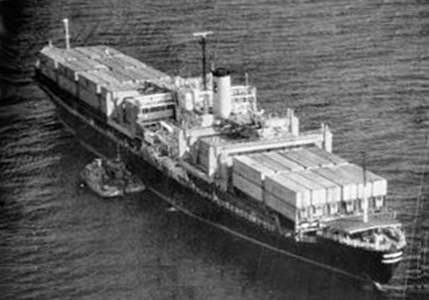


-
Hi Marc - I know I'm coming in late to this discussion, and I agree with you all. But it seems to me from looking at the photos that you could fairly easily raise the steeve of the bowsprit. Cut off the angled support under the bowsprit close to the deck. Replace or adjust the cutoff piece with one that will give you the steeve that you want. Pin it in place with brass if necessary for strength. Redrill the hole for the heel of the bowsprit. Fill and paint and the joints should disappear. Or there could be a problem that I am not seeing. Dan
- 2,699 replies
-
- 6
-

-
- heller
- soleil royal
- (and 9 more)
-
Hi Marc - Beautiful work, and I appreciate how committed you are to the precise fit of all your interlocking pieces. I agree with Kevin that any slight discrepancies will be impossible to notice in the finished model. That said, I also agree with Druxey that the windows as drawn look a little off. But I do not think that it is windows 2 and 5, but the outer ones, 1 and 6, which are a bit too wide and the mullions are a bit too upright. I am sure the finished ones will match perfectly, as usual. Great work. Dan
- 2,699 replies
-
- 5
-
-
- heller
- soleil royal
- (and 9 more)
-
Keith - I double all the compliments and accolades. Top of the tree for imagination and execution. As for the final resting place of the model, it certainly deserves to be in a museum. I hope there is one which would value her. Bravo ! Dan
-
Hi Marc - Beautiful work as always. Thanks for the mini-tutorial on converting plastic to wood. I have saved it to my toolbox and will rely on it as needed. Best wishes to you and your father in his circumstances. And Happy Holidays to all. Dan
- 2,699 replies
-
- 6
-
-
- heller
- soleil royal
- (and 9 more)
-
Good point. I had not measured the drawing. I think your decision is a good one. Stay safe and well Dan
-
Hi Greg - The new tops look good, as do all your masts and spars. They should compliment your hull and fittings very nicely. As for the tops as drawn, I do not know of a contemporary model with such tops, but Captain Bligh's notes on the conversion of the Bethia to the HMS Bounty indicates that he had her fitted with 'gratten' tops, which I took to mean 'gratings'. I suppose that this was to readily shed water in the rainy South Pacific where he was headed. I have seen some modern models with such tops, and some look quite nice. As the man said, "You pays yer money and you makes yer choice. . ." Stay safe and well. Dan
-
Hi Chuck - Beautiful craftsmanship, as always. All the joints are so clean and tight, which is really impressive. Though I do not plan to build a kit, I have read pretty much every instruction manual, article and book, and wrote a few with Jim Roberts. I have to say that your explanations and instructions are up there with the best. They are as clean and tight as your woodwork. Following along in my head I take it a sentence or two at a time and I can actually see the model rising from the building board. Every one building the model is extremely lucky to have you take them through a master class in the arts of the shipwright. Two small suggestions, if I may - - First, it might be a bit easier for the modelers if you gave them the knee of the cathead along with cathead. The slant of its top will establish the angle of the cathead relative to the hull. This then determines the way the bottom of the notch rises from inboard to outboard. Second, you suggest a really sharp chisel for the cuts. I think many of your followers would appreciate a quick lesson in sharpening chisels. I don't know, myself, I just pull out a fresh hobby blade. It is a skill that I should add to my toolbox. Keep on with the good work. Stay safe and well Dan
- 1,784 replies
-
- 7
-
-
- winchelsea
- Syren Ship Model Company
- (and 1 more)
-
Really nice work, Roger. I love the idea of giving the viewer a glimpse of some of the internal details. It should be interesting to see who notices and who does not. Hopefully you will bring the completed ship to the next NRG conference, whenever it is. Looking forward to seeing her in all her glory. Be well Dan
-
Truly excellent results. Congratulations. I am a little old to work my way up the learning curve, but I am blown away by what can be accomplished. I wonder what may be around the next technological curve. I just hope that we will never get to the point of duplicating a fine old wooden model of the Constitution with the push of a button, If you continue as you are going, this will be an amazing model of the Maine. Looking forward to following your progress,. Dan
-
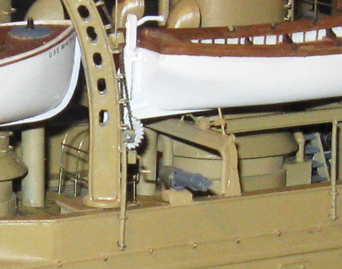
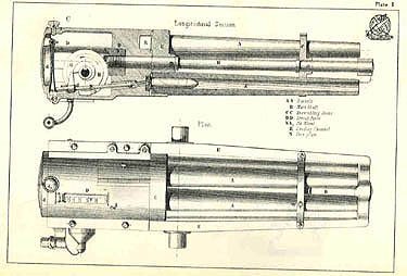
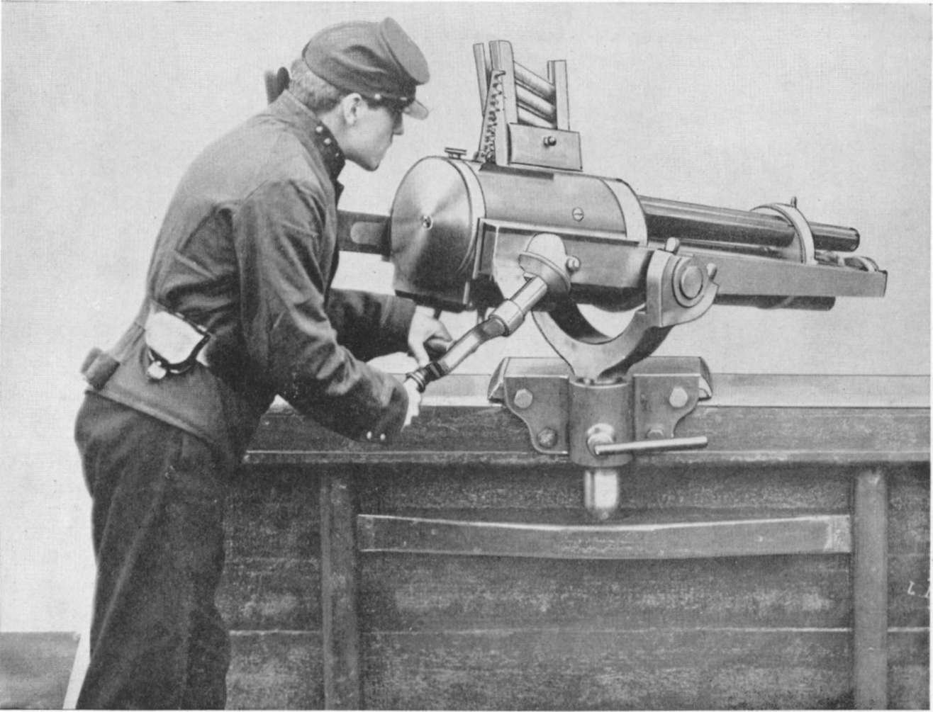
Hi HG - Those small guns moved around a lot. You can put them in several places. It's your choice as Captain. As just an idea, I chose to mount gatling guns near the base of the boat cranes. Here are some images that I relied on, although you probably already have them, and the final result. I hope that helps a little Dan The design of the gun The gatling mounted on a ship's rail The gun on the finished model
-
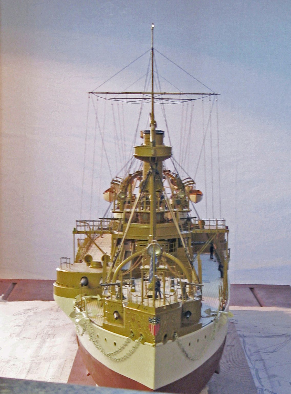
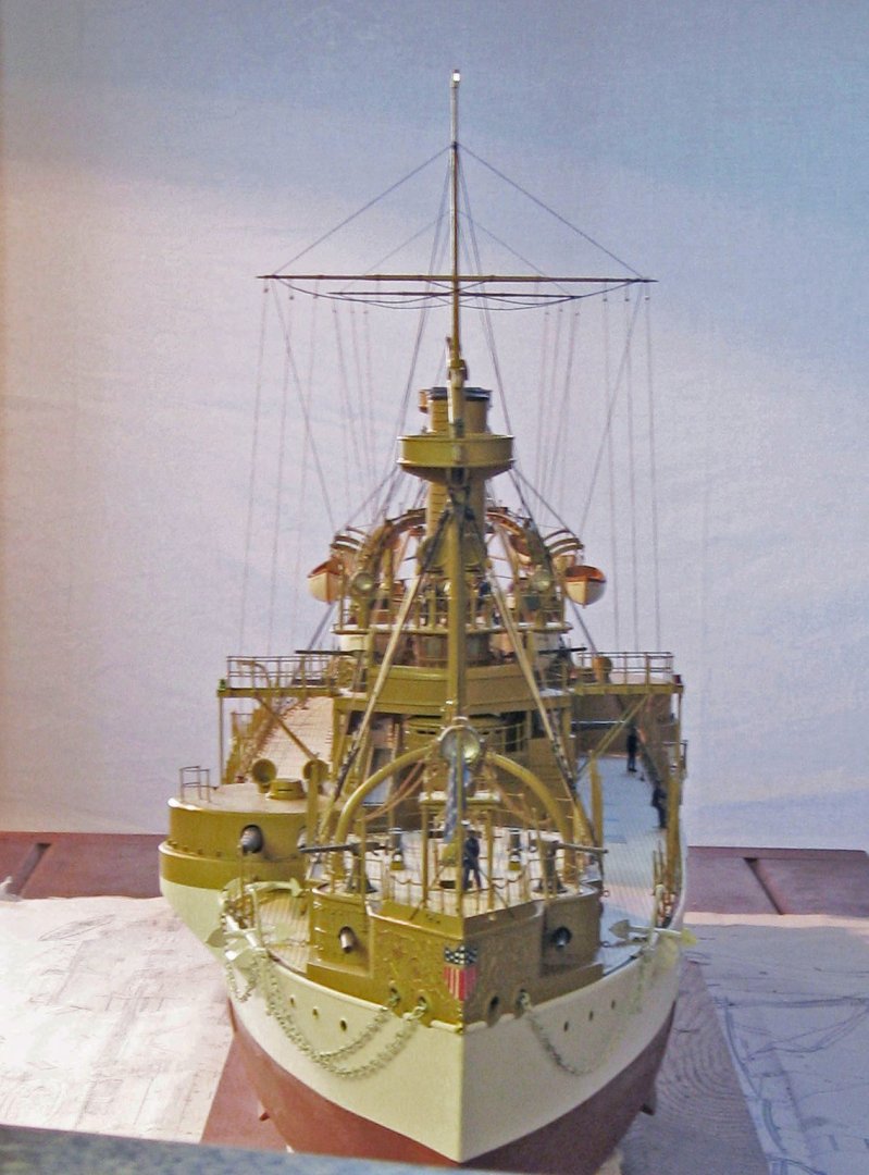
Hi again - I forgot to add my two cents to the discussion of the big gun tactics for the Maine - She was the first "ship of the line" the United States designed after the Civil War, almost 30 years earlier. (The USS Texas was designed later but launched earlier) However, it is not a line of battle if there is only one ship in it. The design of the ship changed radically over several years as the ideas for its proposed use evolved. The final design of the Maine, with its two turrets overhanging the beam of the ship, reflect the final tactical doctrine. If the Maine ever came up against an enemy line of battle, the plan was for her to turn towards the largest of the enemy ships. All four turret guns would fire forwards, ignoring any self-inflicted damage, until the Maine could ram the enemy with her reinforced bow. Fortunately, she was never called on to do so. Here is what the enemy might have seen.
-
Hi HG - Love the progress that you have made on the Maine. The 1-pound Hotchkiss gun and the boats are beautifully detailed. Looking forward to seeing how the gatling guns will print out. I don't do R/C models, so I can only imagine the added technical problems that have to be solved. I agree that she is a bit light at the stern at the moment, but with a slower speed she should look really impressive. Stay safe and well Dan
-
Hi Marc - Not sure I remember which pieces of tackle you mean. If you mean the hooks, they were probably from Syren. Wooden blocks from Warner Woods, but Lloyd is out of business. Small metal blocks in your scale are available from Bluejacket. If you can send me a photo I can check again. Dan
- 2,699 replies
-
- 3
-
-
- heller
- soleil royal
- (and 9 more)
-
Hi Marc - Back in the city where I can get on MSW. Went back over all your progress in the last months and am really blown away to see how well she is coming out. I think your color choices are excellent, and your workmanship, as always, top notch. I'm looking forward to seeing her in New London, unless we can get a club meeting together before that. Ad astra per aspera, my friend. Dan
- 2,699 replies
-
- 4
-
-
- heller
- soleil royal
- (and 9 more)
-
Hi Rob - Very nice work on the breaching ring irons and the deadeye chains. They will show up beautifully as details that will give you a knowing smile when you see them on the completed model. PS - Woolsey was not the only one supervising. Ensign James Fennimore Cooper was also there and working on the ship. Looking forward to future progress. Dan
-
Michael - You can add my sincere wishes to all the others for a speedy and complete recovery.\ Hang in there , my friend. Dan
-
Hi Mark = Your model is coming along very nicely. Welcome now to the wonderful world of carving. It really is wonderful, despite a pretty steep learning curve. As others have said, the more you do, the better you will get at it. Having worked my way up the curve, I have some thoughts and a tip that works for me. First, there are two basic methods for miniature carving - chip, or knife carving and rotary carving. In the first, the unwanted material is removed with a blade or chisel. In the other, by burrs and bitts in a Dremel or similar. To see an excellent use of the first method, check out Hubac's Historian's build of the Soleil Royale. Although he is carving styrene, the principles are the same. To see what rotary carving is about, look at my build of the Queen Anne's Revenge [just click on it below in my profile] The carving of the figurehead starts on page 2 I do 95% of my carving with rotary tools and only the last little bits with a knife to get a crisp edge where I need it. It is just a process of removing everything that does not look like the piece that you want. As for the tip - When you begin carving the flags and lances, mount the carving blank to a larger disc of scrap wood. Use cyano or rubber cement, or another solvent based adhesive. The round shape will let you easily turn it so you can attack the work from all angles. The backing will support the thin shafts of the lances and other delicate details. When you are done soak the entire piece in acetone or denatured alcohol until the carving comes free without force. I hope that this helps a bit. Keep up the excellent work. Dan
-
Hi Chuck, and all - A quick internet search led me to these, from Woodland Scenics - https://scenearama.woodlandscenics.com/show/Item/SP4454/page/1 5 Revolutionary soldiers, officers and men, who look like they could be modified very easily. Only $9.99 I also found highly detailed individual 75mm figures, including a Royal Navy commander https://www.sabotminiatures.com/The-Commander-Royal-Navy-XIX-sec-75mm-p/best_75018.htm Not cheap at about $50 each. Hope that helps Dan
- 1,784 replies
-
- 4
-
-
- winchelsea
- Syren Ship Model Company
- (and 1 more)
-
Thank you all so much for your kind words. Although I build and restore models for the satisfaction of creating and preserving artworks for those who will come after, I write up the process for my fellow modelers. Without your encouragements I would still build, but I would probably not write. Thanks again. Dan
- 95 replies
-
- 13
-
-

-
- POW
- Bone model
- (and 2 more)
-
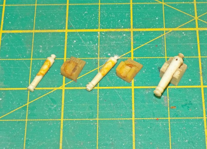
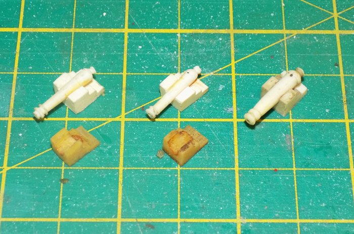
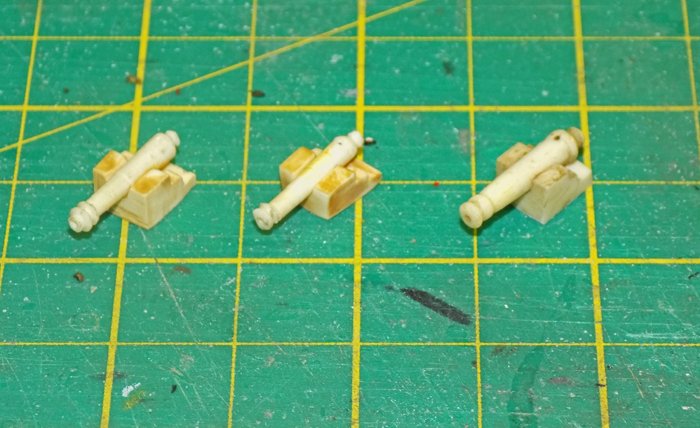
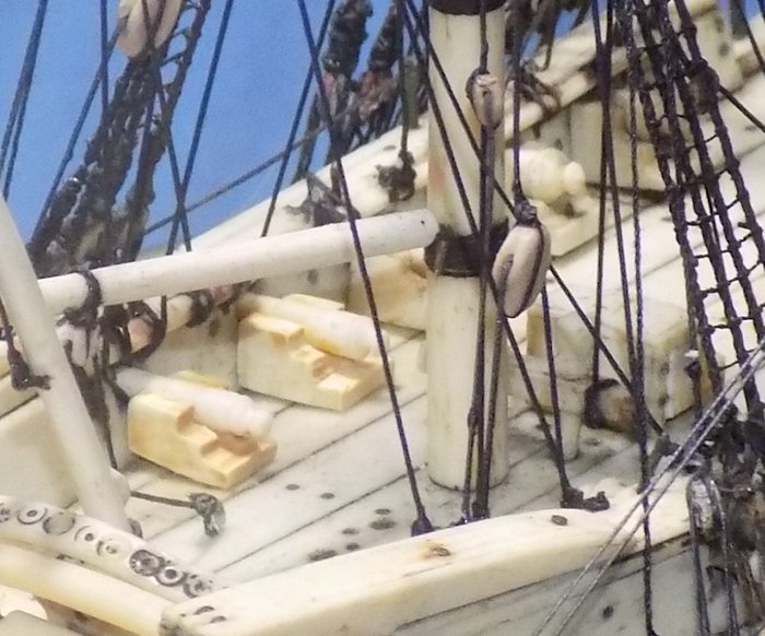
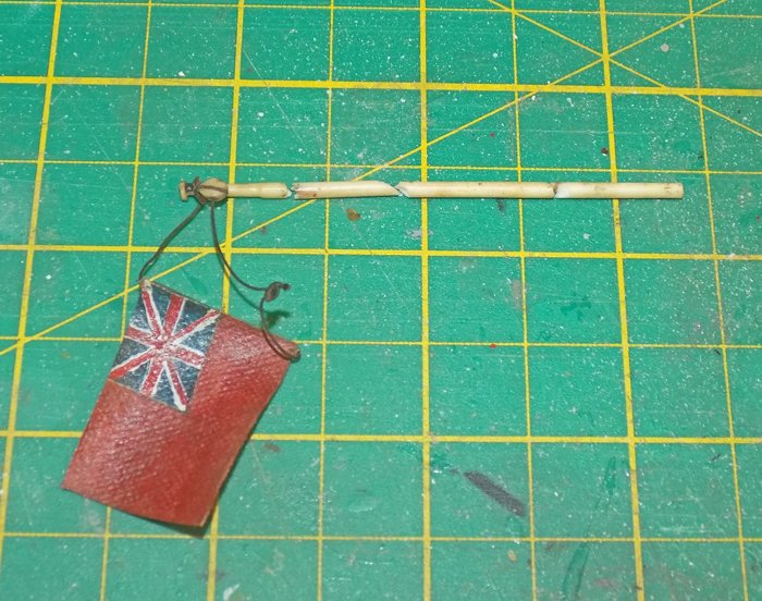
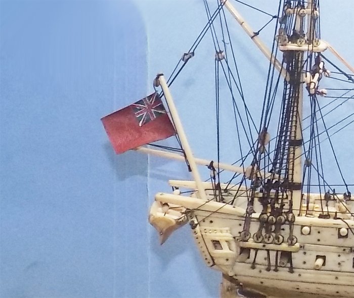
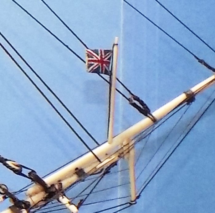
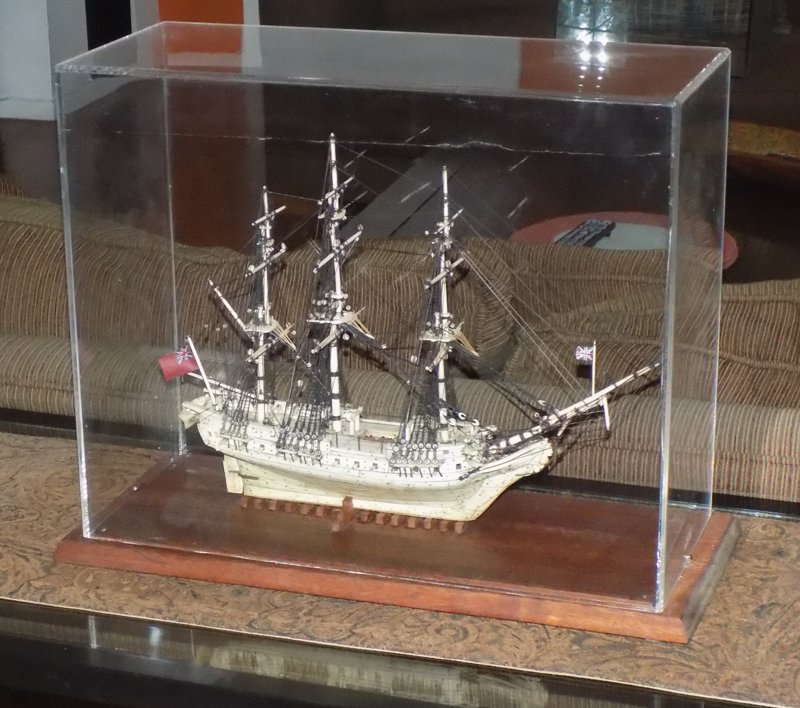
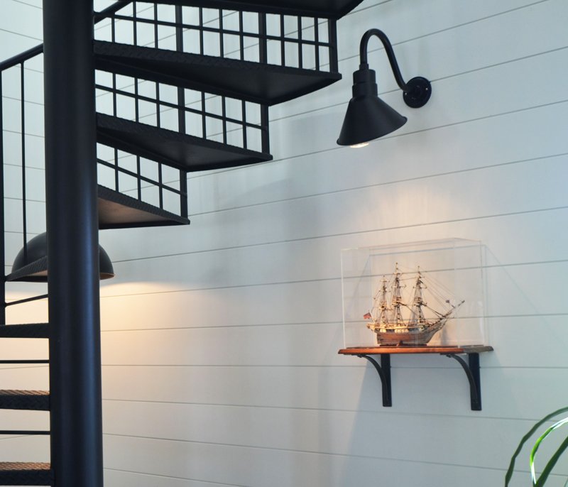
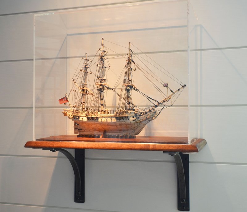
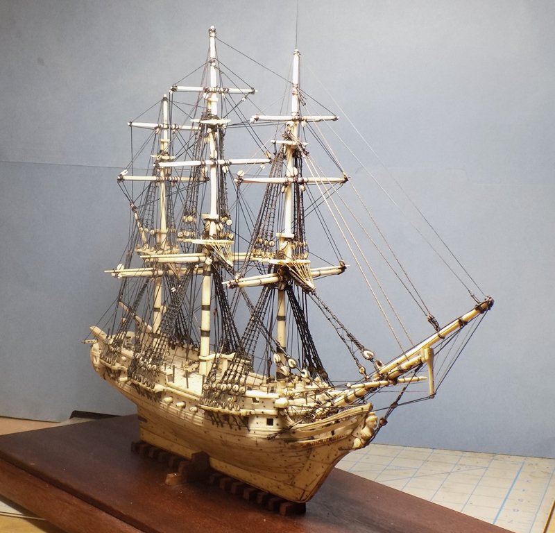
Hi all – Here is the finish of this restoration build log. I begin with the cannon. Two of the guns were detached when received, with one having a carriage made out of a completely different material than the others. A third cannon was on a similar carriage of unknown material. I removed it so I could work on it. I cleaned up the old glue from all of the guns, then fashioned two new carriages from ivory. The barrels were set on the new carriages and secured with cyano. The new carriages were aged with coffee grounds. Actually, they took up the color a bit too well, so the brown was sanded back a bit after the photo was taken. When I was happy with the color they were installed on deck with PVA glue. The originals were pinned through the rear of the carriages and into the deck, but there was no room for such reinforcement, so they will have to rely on the strength of the glue itself. Judging from other models that I have worked on, I am confident that it will be at least 50+ years before anyone will have to worry about glue failure. Finally, I mounted the two British flags. The large ensign at the stern was set on an ivory staff, although it was shown detached in the client’s original photos. He failed to bring it with him when he delivered the model, so he dropped it, and a few other detached pieces, into a plain envelope and mailed it to me. When it came the delivery process in the Postal Service had broken the staff into four pieces. I cut a 1/8” square piece of ivory about 2 ½” long and made it octagonal with sanding drums. Further sanding rounded it to an approximate cylinder. Finally one end was chucked into a Dremel with a bit of paper towel to protect the ivory from the jaws of the chuck. On low speed the shaft was held against a large flat sanding block and turned to a cylinder. The original halyard block and line were used to mount the flag to the new staff, which was slid into two metal fittings on the inside of the taffrail. I also took a moment to hang the boat from the davits at the stern. At the bow the small flag was remounted in its hole in the jib boom. With a quick cleaning and oil rubbing of the base the repair was finished. To replace the heavy glass cover a new acrylic cover was ordered and set on the base. Two small brass nails on the short sides were installed by drilling through the plastic and into the wood of the base. These will prevent the cover from coming loose if anyone picks it up by the cover rather than from underneath. The client mounted the model on a pair of heavy brackets in a prominent place in his home. He has told me that he and his family are very happy with the restoration, as am I. I hope you all have enjoyed the journey as well. I can only hope that the model will last another 200 years and represent a glimpse into a long-gone world of naval history and art. Let me know if you have any questions or thoughts. I will be back again with some more of the models that I am building for the Merchant Marine Academy museum. Until then . . . Stay safe Dan
- 95 replies
-
- 31
-
-
-

-
- POW
- Bone model
- (and 2 more)
-
Hi Mark - That's new information for me. Thanks. I wondered why the bench was so bulky. No, the ship is clearly intended to be English. But like most of the bone and ivory models, she was probably built by French naval prisoners. Having a mix of details is not unusual. Most of the models were made to be sold to English customers so they have English names and flags, but may still have French details. I just finished a review of the ship model collection held by the Museum of the City of New York. They have some very nice POW models, one of which is clearly English with several flags, but has a figurehead of Mademoiselle Liberty with her easily identifiable cap. Perhaps a little dig at their captors? Stay safe
- 95 replies
-
- 4
-
-
- POW
- Bone model
- (and 2 more)
-
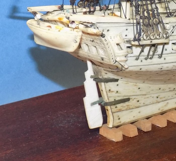
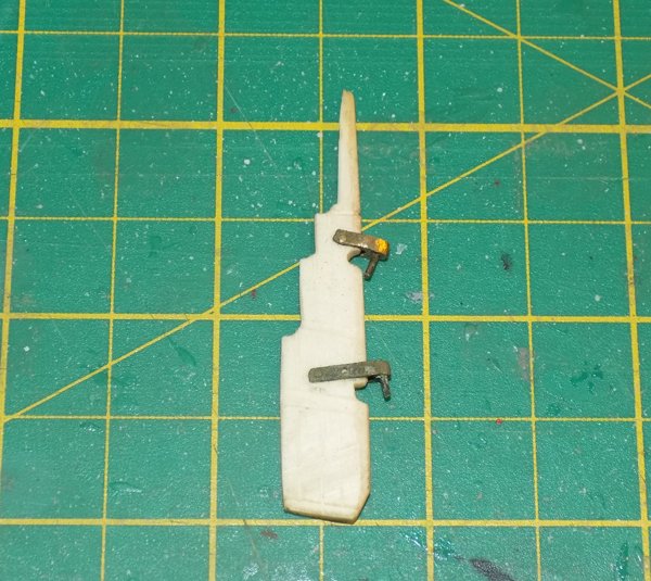
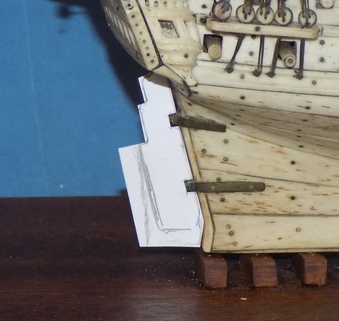
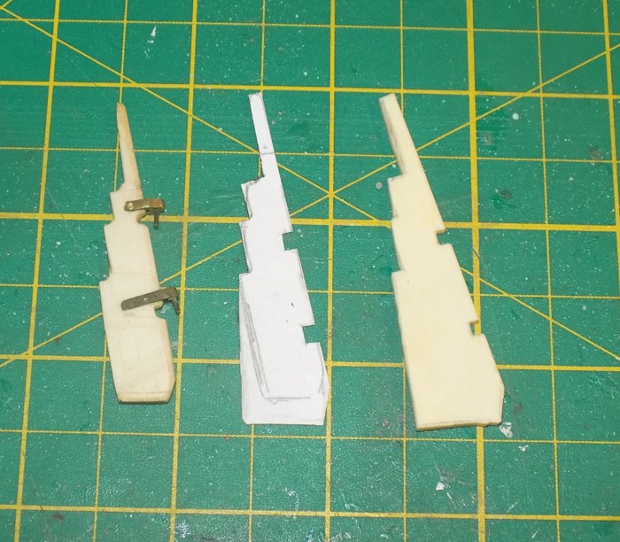
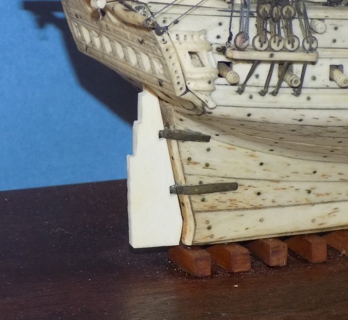
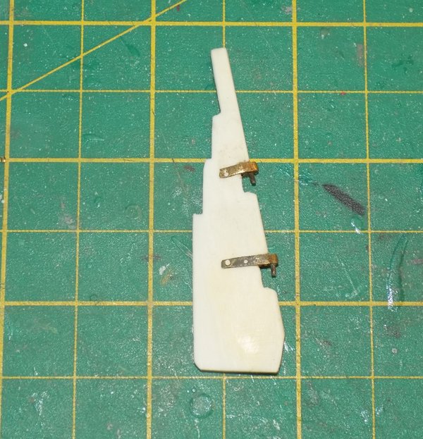
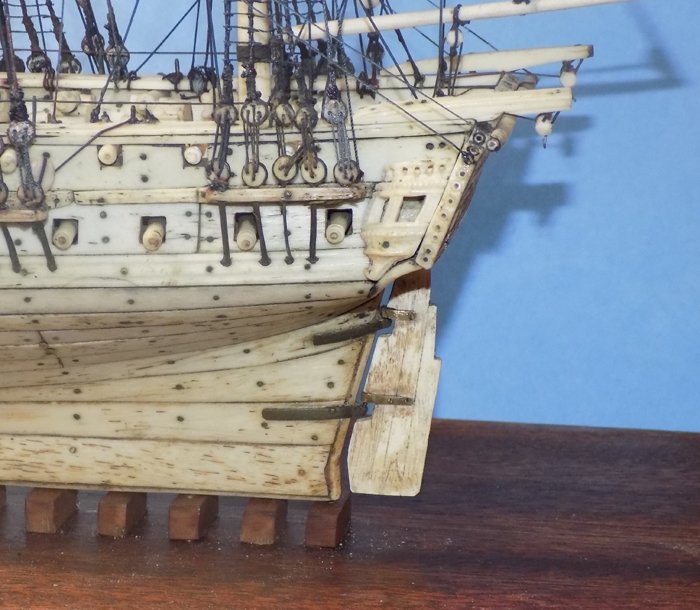
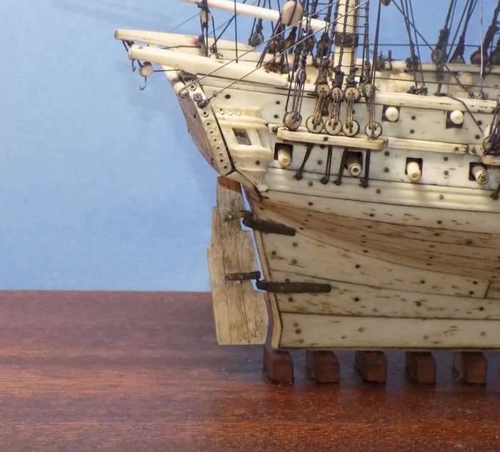
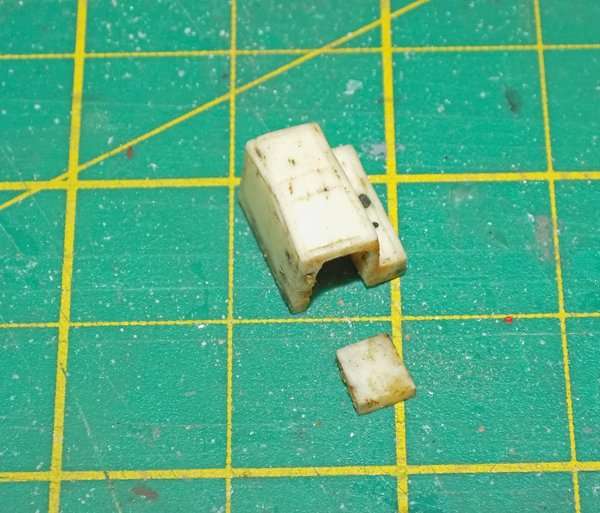
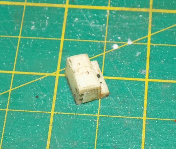
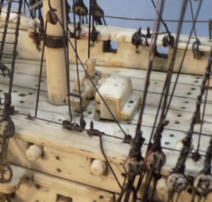
Hello and Happy Passover / Easter [delete whichever does not apply] – Thanks as ever for the many likes and compliments. The next task was to repair or recreate the several fittings that were either detached, damaged or incorrect. The most obvious was the rudder. Here it is as received – too small, too white, and hung badly. It was removed and examined, where I found that the brass pintles were properly pinned through the rudder, but set at incorrect angles and too far forward so the gap between the rudder and stern post was too great. Drawing the outline of the existing rudder onto a piece of card stock I fitted the pattern to the stern post and the gudgeons. I left extra card on the aft side and the bottom so I could draw a proposed new shape and refine it before cutting ivory. Here are the three initial stages of shaping the new rudder. The new rudder blank was carved out of ivory and test hung on the gudgeons. After final shaping the pintles were transferred to the new rudder and pinned through with brass rod. Once I was happy with the shape and how it hung on the gudgeons I gave it two dark vertical lines to indicate the joints between the three portions of the rudder blade. This was done by drawing on the blank with a soft lead pencil, then tattooing the graphite into the ivory with the back of a hobby blade. Once that was done I ‘aged’ the rudder with brown coffee grounds and added a bit of grey tone with ebony stain. It took up the colors in the deep scratches that I purposely left by sanding with fairly coarse paper. I think the combination of techniques resulted in a convincing look that matched the bone planks of the hull. Next, on deck there was a bench for the officer of the deck which can be seen in some of the initial photos. It turned out to be loose, so it was removed and stowed until now. I found that it had been hollowed from one side (I don’t know why) with the opening closed with a small square of ivory. This little piece did not fit well, so I shaved off the edges until it did. A drop of cyano applied from the inside secured it back in place. The restored bench was reset on deck and secured with PVA glue. The next posting will be the final segment of this build log. I will write it up soon. Till then, stay safe. Dan
- 95 replies
-
- 16
-
-
- POW
- Bone model
- (and 2 more)
-
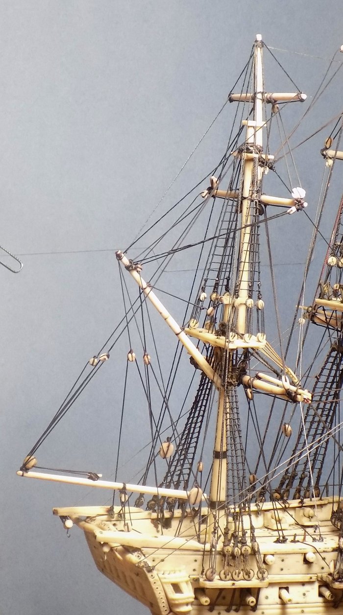
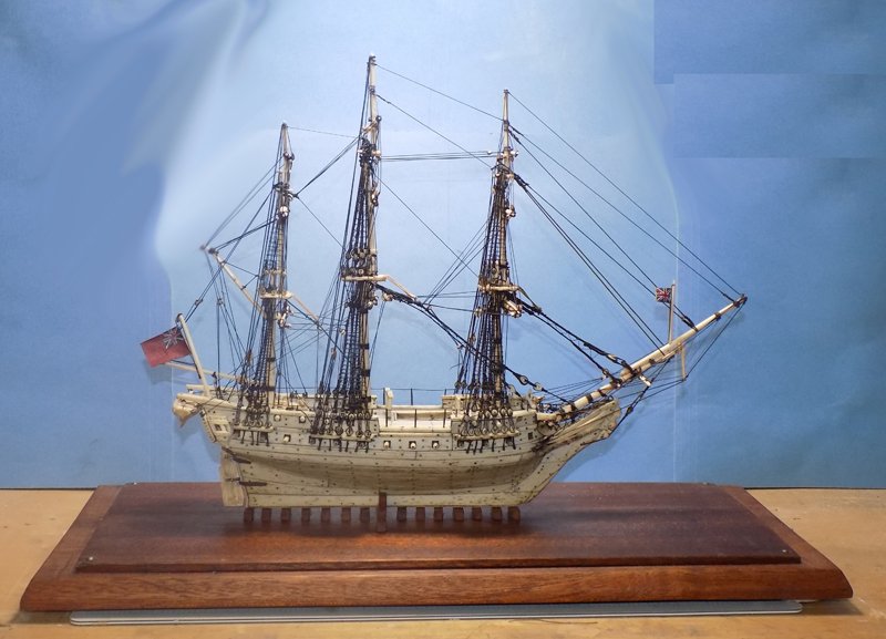
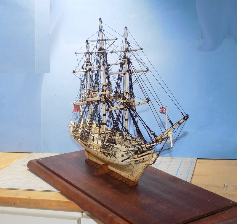
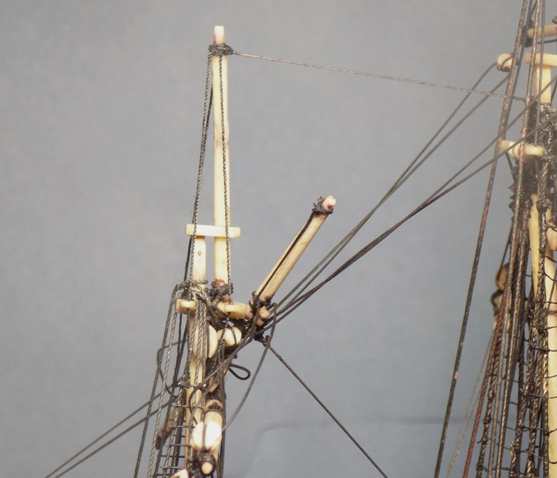
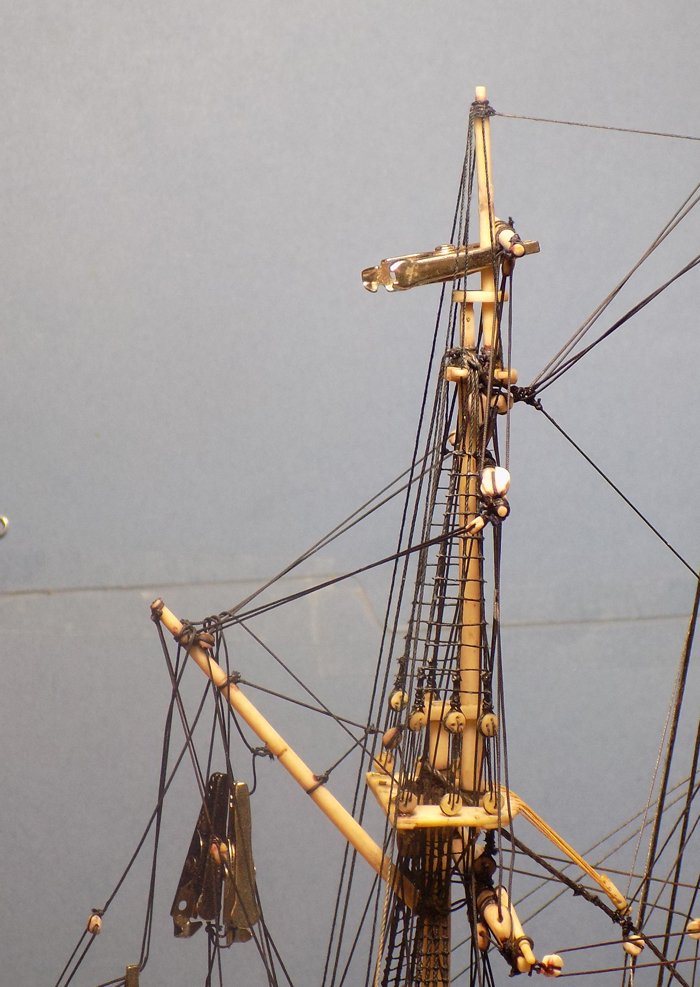
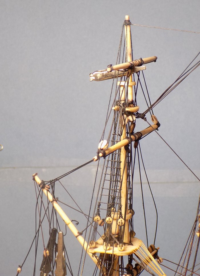
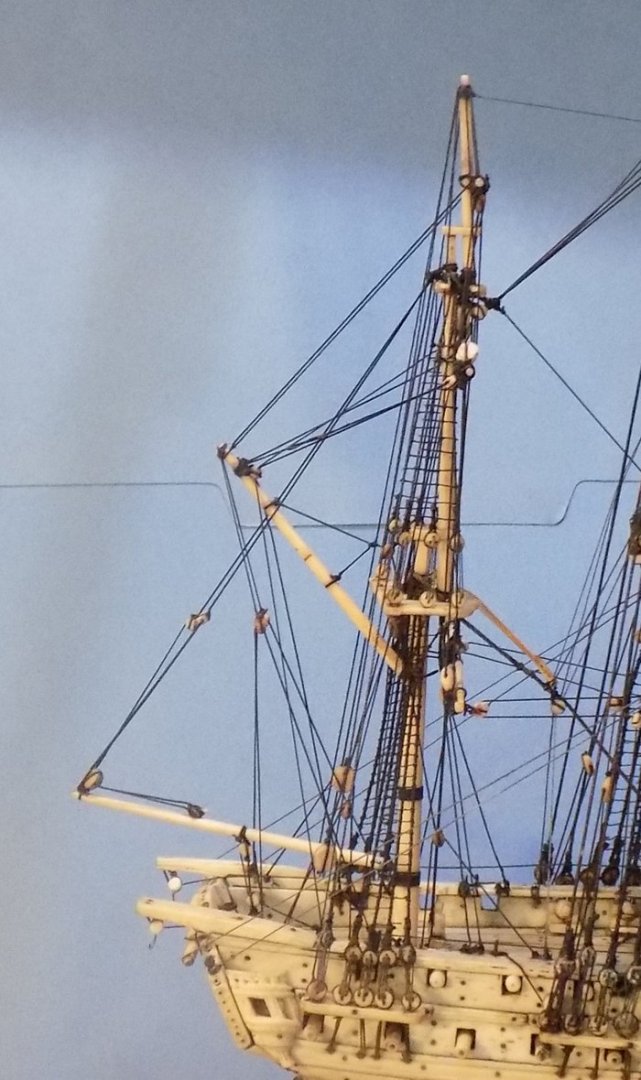
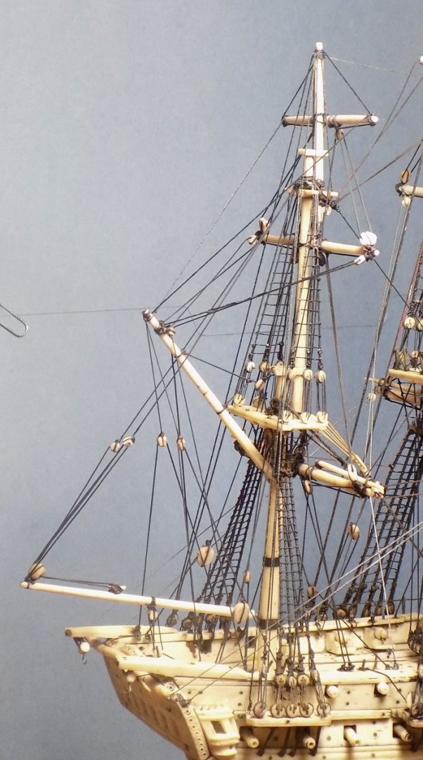
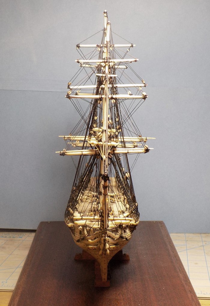
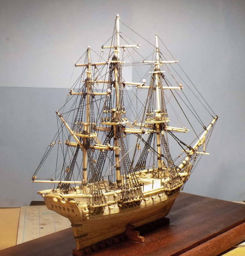
Hello again to all – Thanks for the likes and compliments, and especially from you, Michael, whose own restoration work is so exceptional. Eric – passing along some of the tips and techniques that I have learned over the years is one of my greatest pleasures in this activity. There are lots more in my earlier build logs if you go through them. As for the model, it was now time to finish off the rigging repairs. With the mizzen topmast shrouds done I reattached the topmast stay. It is a smaller diameter than it should be, but the main t’gallant yard braces are tied to it, so I used it in place. Then the topmast backstays were created from new line and secured to the final deadeyes on the mizzen channels. You can see the head of the backstays here and the deadeyes in a later photo. I strung the t’gallant shrouds through the topmast crosstrees and tied them to the shrouds, then ran the t’gallant stay from the tip of the mizzen mast to the topmast doubling of the main mast. I ran the t’gallant backstays from the tip of the mast to eyebolts on the mizzen channels. Although the eyebolts were new, I found holes in the correct locations on the channels which had originally held eyebolts, confirming that my rigging layout was correct. The mizzen t’gallant yard was lifted and clipped to the mast. This let me easily string and tension the yard lifts, which was done just after the photo was taken. The lifts for the mizzen lower yard were also later tensioned by taking the slack through the blocks and down to the belaying pins at the deck. Now the rigging to the driver gaff and boom were restrung, including the topmast yard braces, the topping lift, the vangs, and the rest of the lines that had been detached so I could work on the mast. After final balancing and tensioning of any slack lines the rigging was done. At the aft end of the mizzen channel you can see the deadeyes for the mizzen topmast backstay and the eyebolt for the t'gallant backstay. From dead ahead this photo reveals that while I was able to reset the masts and yards to a great extent, there is still a bit of unwelcome variation in the angles of the yards relative to each other. The largest issue is the main topmast yard which was unfortunately glued in place by an earlier restorer and which I could not adjust. Nonetheless, I think the overall look is acceptable. So here are two photos of the fully rigged model, taken from the stern quarter and bow quarter. I believe the client will be pleased. The final tasks will be to replace the unsatisfactory rudder, the cannon carriages, and the flags. I will post that soon. PS – I have been having some issues, as you can tell, with getting the lighting right for taking the photographs. The bright white of the ivory does not show up well unless the color saturation is turned down so far that the blue background turns grey. I just bought some additional lights and I am playing around with the flash settings on the camera, so I hope that the balance of the photos will come out better. Stay safe Dan
- 95 replies
-
- 25
-
-
-
-
- POW
- Bone model
- (and 2 more)
-
Great work, both of you. The workmanship of the hull is crisp and pristine, the carvings beautiful and stylish. Thanks for posting again and letting us share your success. Looking forward to the rigging journey. Dan