shipmodel
-
Posts
941 -
Joined
-
Last visited
Content Type
Profiles
Forums
Gallery
Events
Everything posted by shipmodel
-
 Sorry. My old eyes missed the open seats of ease. Just a senior moment. Dan
- 2,699 replies
-
- 2
-

-

-
- heller
- soleil royal
- (and 9 more)
-
Hi Marc - Beautiful work on the gratings. I bet there was a large dram of something fortifying when you finally breathed a sigh of relief at completion. Will there be open seats of ease for the crew or just enclosed ones for the officers? Dan
- 2,699 replies
-
- 3
-
-

-
- heller
- soleil royal
- (and 9 more)
-
Hi Cisco - Glad you enjoyed the conference. The New York Shipcraft Guild had a wonderful time bringing it to all our friends and fellow modelers. I hope you took away some inspiration from all the excellent models on display. I'll look forward to seeing you at next year's conference when I will not be the host and will have some time to chat. See you there. Dan
-
Keith - I'll be following along for the sheer joy of watching you work and following along your thoughts. This will be tremendously entertaining and informative, as always. Thanks for sharing the journey. As for the hailing port - to my eye the name is incised into the transom. If the hailing port is unknown at this point, or can be changed later, it would make more sense to paint it on just before launching. Yes? Dan
-
Hi Sbaker - 1710, the year that QAR was built, is a little late for a spritsail mast. R.C. Anderson says that they were pretty well phased out by then, especially in smaller ships which did not need the leverage of a forward sail to tack through the eye of the wind. Budriot does not show one in his plans of Le Mercure, so I did not put one on. That said, there was a great deal of variation in the rig of ships in this somewhat transitional period, even among ships of the same size built by the same nation. If you are building your own QAR model, make your best choice and stick with it. Best of success. Dan
- 241 replies
-
- 3
-
-
- queen annes revenge
- pirate
- (and 2 more)
-
Ron - Really nicely done and fitted. I applaud your striving for perfection, even where no one but you will ever notice. Be well Dan
-
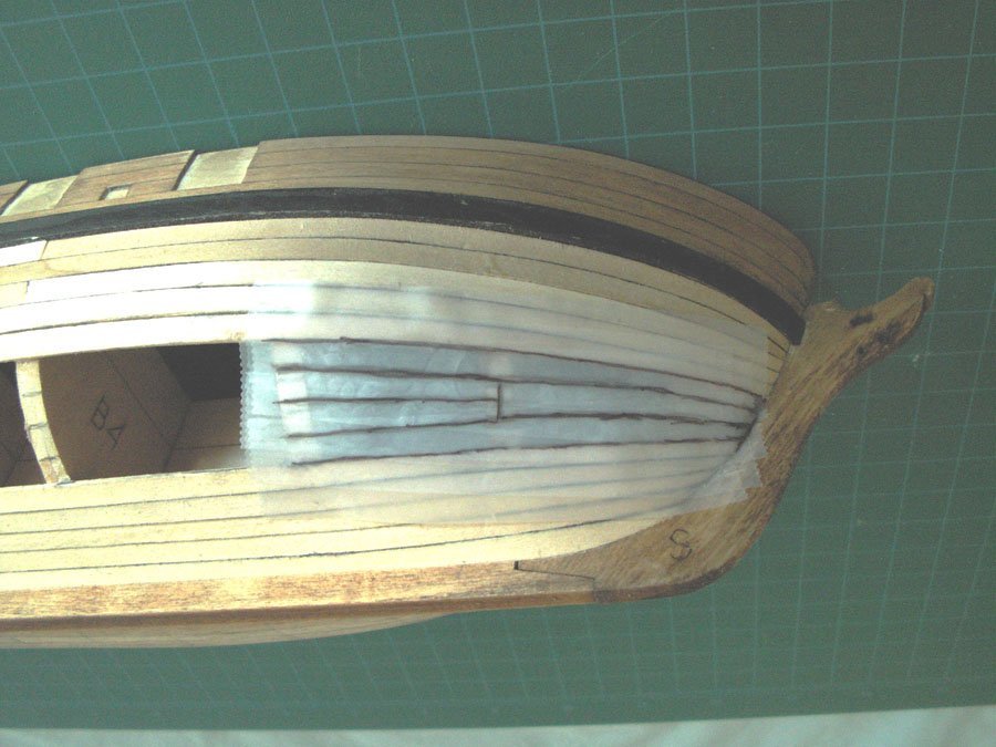
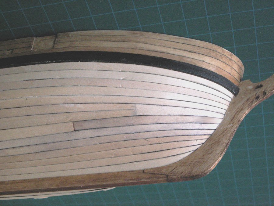
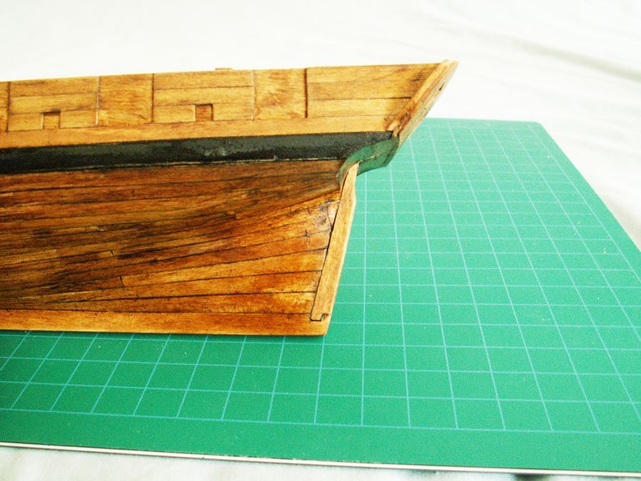
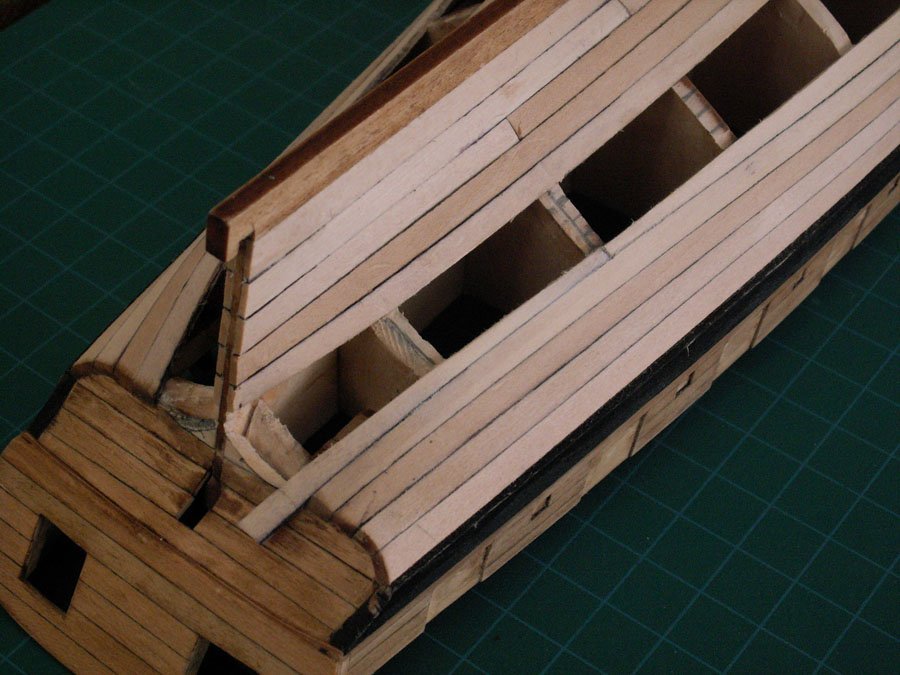
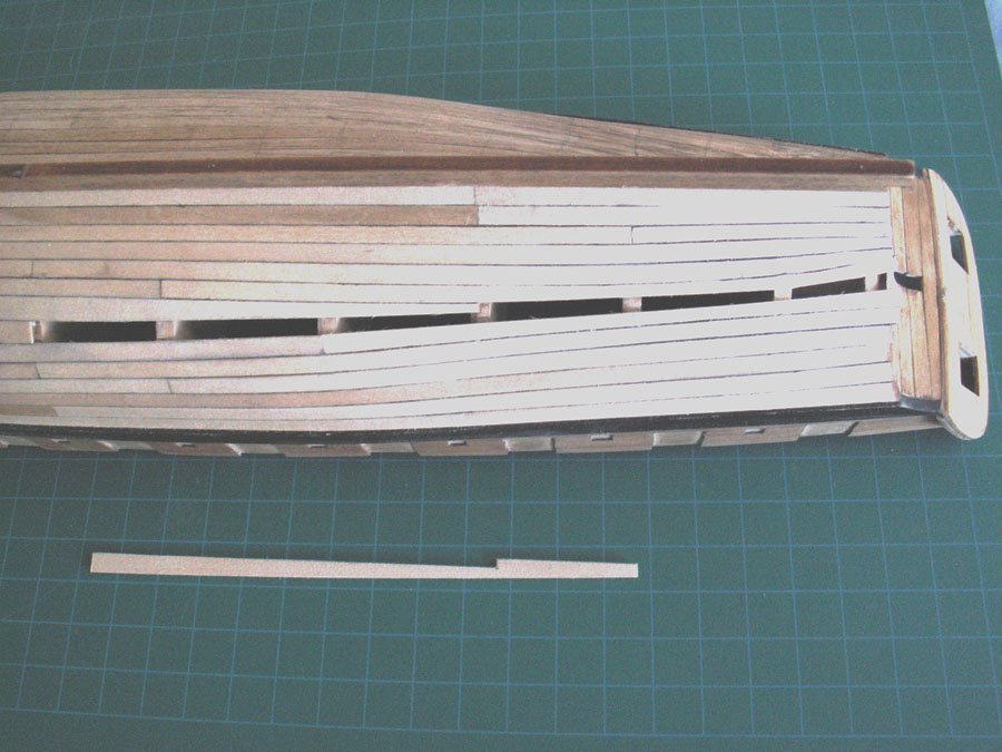
Hi Cisco - I'm really enjoying reading your build log. I applaud all your work climbing up the learning curve of hull planking. Making a complete planking diagram is something I never attempted, and yours is quite well done. As you said, you now have a much better understanding of plank widths and butt spacing. However, since this is your first shot at complicated planking, I think you may have set up a more difficult task for yourself than necessary. I hope you don't mind if I offer some practical advice from 35 years of doing this. The problem, based on my experience, is that your stealer at the stern and the drop plank (stealer) at the bow come too early in the process. A stealer doesn't just compensate for the curve of the hull, it allows the model shipwright to adjust the run of the planks to straighten them out as the hull closes up. Your planking plan has the drop plank being the first plank that you install under the wale. Whether this is the first plank or the last that you put on, it is going to be hard to adjust easily to get a nice look. I find it easiest to plank up from the garboard and down from the wale alternately. Here is a hull that I did a while ago. It has a similar shape to the hull of the AVS that you are doing. At the bow the planking strake runs the full length of the hull, but the planks are tapered to about 2/3 of the standard plank width when they reach the stem rabbet. After each plank is installed the edge is eyeballed and straightened, if necessary, with a sharp edged file. It is also shaped to match its partner on the opposite side. This photo is after 5 planks up and down. The remaining space is covered with lengths of translucent tape and the final plank shapes are drawn on, much as you have done on the solid hull. 1 The tape is transferred to planking wood and the shapes are cut out and fitted. 2 At the stern the process is similar, but the planks up from the garboard are flared to fill the wider space at the sternpost. 3 As the hull closes up the remaining space becomes evident. Tape is used again to draw in the final plank shapes. 4 Until the final plank can be cut, fitted and installed. 5 As I said, this is based on my experiences. There are several other building methods that work equally well. If mine is not to your liking, you can find excellent examples in many of the build logs on this site. Whatever you do, best of success. Dan
-
Hi Roger - She is coming along quite nicely. Well done, sir. I am not brave enough to attempt to work in metal, so I am a bit in awe of your work. Dan
-
Hi Marc - I remember from my youth that the optometrist always used to bend the plastic eyeglass frames after heating in a tray of hot sand. Maybe it would be more controllable than boiling water. It seems to be available for $1.95 for a 1 pound bag here - https://www.homesciencetools.com/product/sand-fine-white-1-lb Your work is impressive as always. Dan
- 2,699 replies
-
- 4
-
-
- heller
- soleil royal
- (and 9 more)
-
Hi Gerard - I guess I did not realize how small French sailors of the period were. And now back to appreciating Johann's modeling mastery. Be well Dan
-
M. Delacroix - You are certainly correct when you say "Using the construction plans of a merchant ship to deduce those of a 40-gun frigate is a very hazardous venture whose credibility can be seriously questioned." However, that was not my point. Deducing the structure and appearance of Queen Anne's Revenge (built privately as Le Concorde, a small frigate) from contemporary sources was done by the History Department of East Carolina University, which is responsible for the underwater excavation and conservation of the actual ship. I simply followed their directions to use for the external structure the Admiralty plans of Beaver's Prize and for the internal structure and details to use M. Budriot's reconstruction of Le Mercure. My own knowledge, or lack of it, didn't come into it, just my model shipbuilding skills. My point was only that the plans of Le Mercure are internally inconsistent. No ship would have a gun deck with only 4 feet of headroom. The sailors would have had to fight on their knees. Something was wrong. My thoughts and solutions to this problem are all laid out in my build log. I hope you will read through it and let me know if you have other ideas or if you reach any different conclusions. I applaud M. Budriot as one of the " greatest, specialist in French naval archaeology." I applaud Howard Chapelle for his expertise in American shipbuilding and Brian Lavery for his works on English naval construction. But these are men, not gods, and I have occasionally had issues with their plans and/or conclusions while still honoring the huge contributions they have made to our current knowledge of ship design and construction in the Great Age of Sail. Thank you for engaging in an entertaining discussion. Dan
-
Yes, we should allow M. Budriot some leeway in his efforts, but we should also draw a line at some lazy techniques that affect the work of those that he is writing for. In my case I used his plans for the light frigate Le Mercure when I was building the Queen Anne's Revenge, Blackbeard's flagship. Although I found his detail drawings to be excellent, both in drafting and historic accuracy, there was a major problem with the hull. It seemed as though he had simply scaled down the plans for a somewhat larger frigate. This meant that as drawn the gun deck would have been 4 feet high. I had to digitally remove one of his lower decks to move everything down to give me enough headroom for the sailors to work the guns. This then affected the height and spacing of the gunports, which affected the shroud chains, etc. All in all, it added a good deal of unnecessary work. All of the details are in my build log if you are interested. I was not overly concerned with this once I had corrected it. Since no one knows exactly what the QAR looked like, I had a lot of freedom to make reasonable interpretations, unless they contradicted some piece of the actual ship that had been recovered from the sea floor. However, for those in our community who build to the highest tolerances and the best historic research, I can only advise caution with M. Budriot's work. To use an often quoted truism - "Trust But Verify." Be well Dan
-
Chris - I stand corrected. As of last week she is scheduled to move from IYRS to Mystic Seaport for final restoration and finishing. This is estimated to take another three years. I will be stopping in from time to time, as I did at IYRS over the years. Dan
-
Hi Keith - Whatever yacht you eventually select, I recommend the resources and library at IYRS, the International Yacht Restoration School, at Newport, Rhode Island. They are very accommodating, and have books, plans, photos, and other materials on almost any yacht you can select, especially sailing ones. They are the people who restored Coronet to its pristine condition. Best of success. I'll be looking forward to your build log. Dan
-
Superb, Keith, as usual. Were the rope coils occasionally hung on the belaying pins or were they always on deck? Dan
-
MONTAÑES by Amalio
shipmodel replied to Amalio's topic in - Build logs for subjects built 1751 - 1800
Amalio - Let me join with all your other fans to say what a wonderful woodworker you are. I am frequently inspired when looking at your precision and perseverence. Many of my models, even the museum pieces, are done in 12 months or less While yours is still in the dockyard after more than 12 years. My hat is definitely off to you, sir. Dan -
Marc - Glad you came through covid (again) so well. Nice work. I think you have solved some of the trickier fitting problems around the headrails. Looking forward to seeing her in person. Stay well Dan
- 2,699 replies
-
- 8
-
-
-
- heller
- soleil royal
- (and 9 more)
-
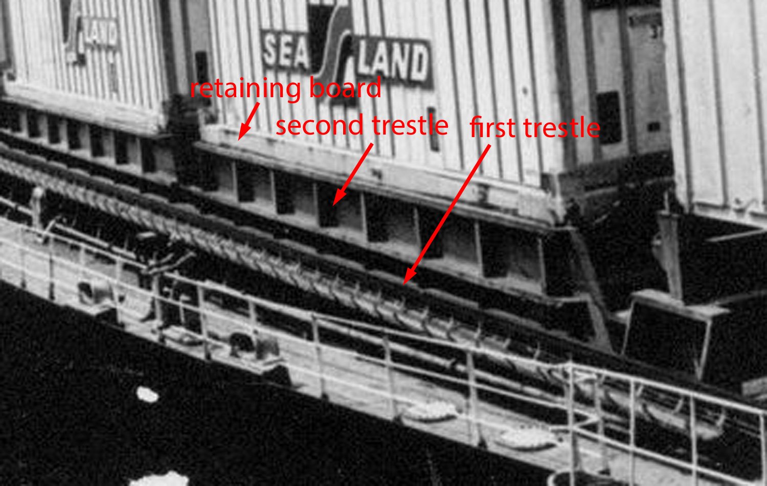
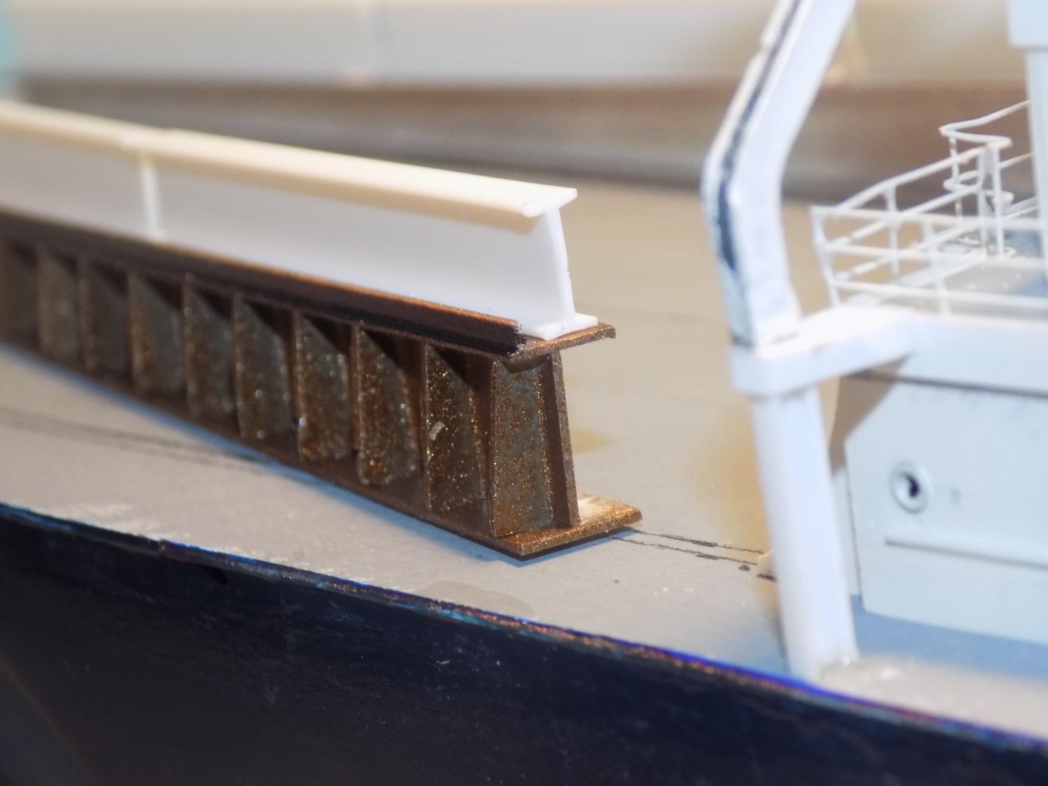
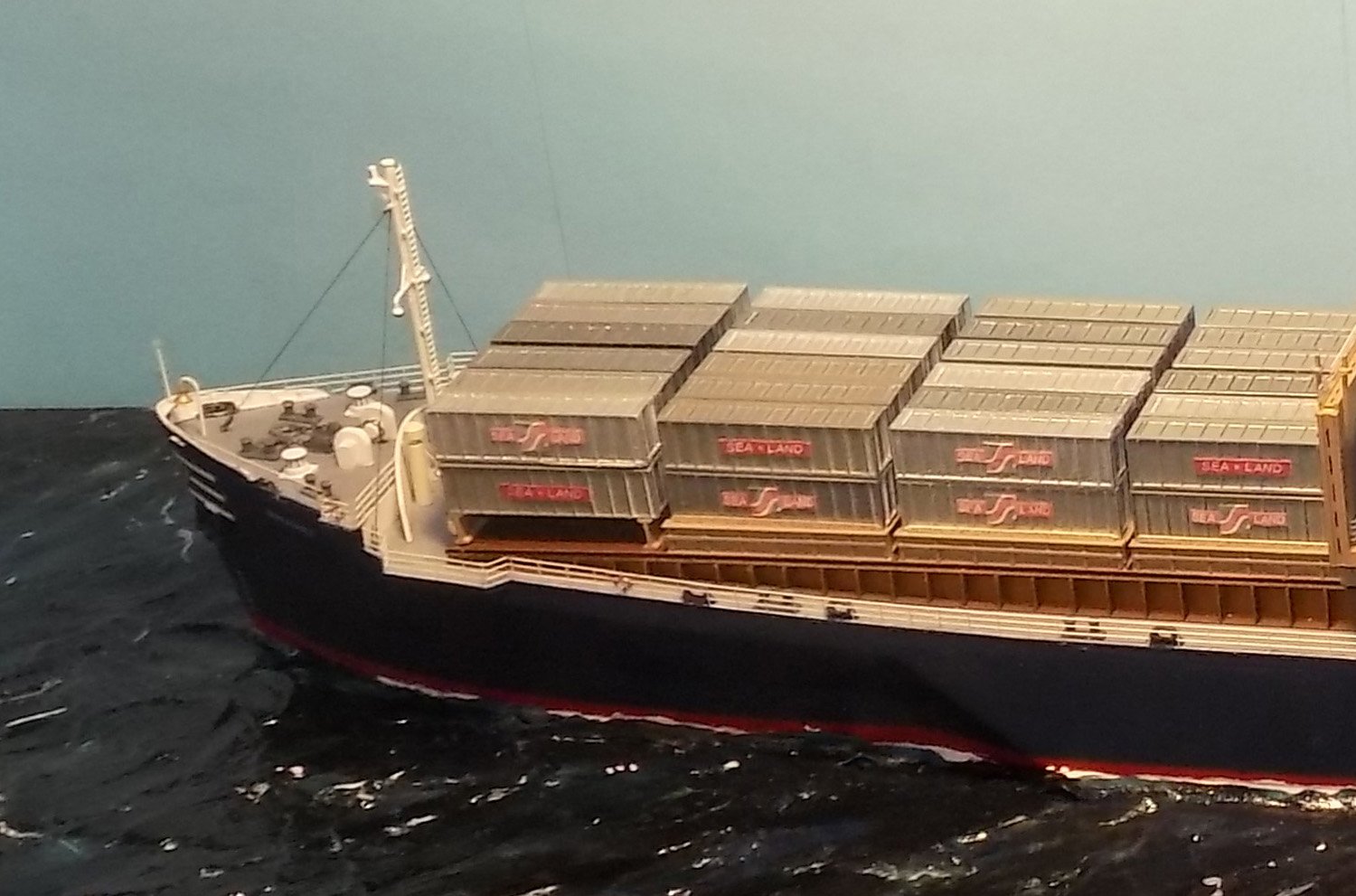
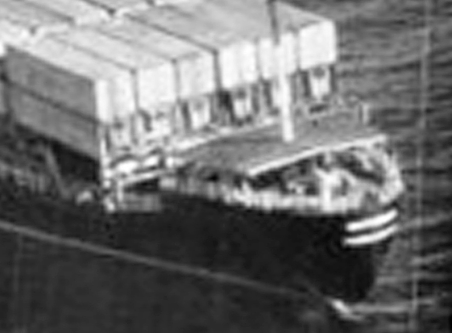
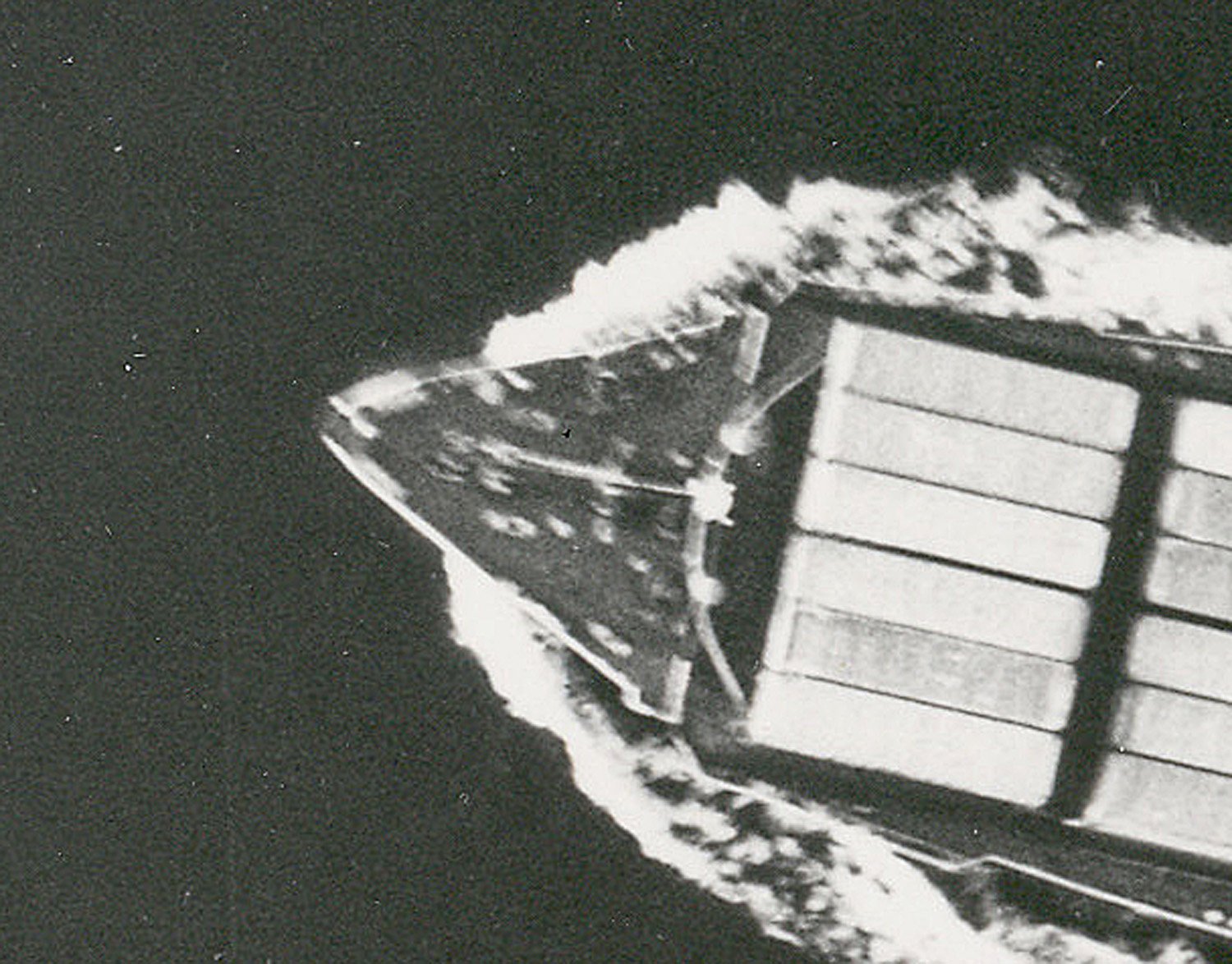
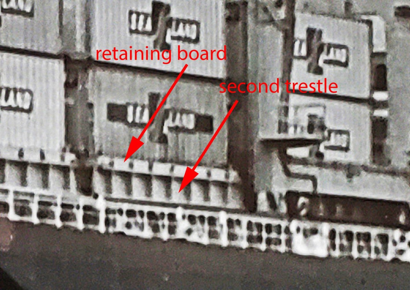
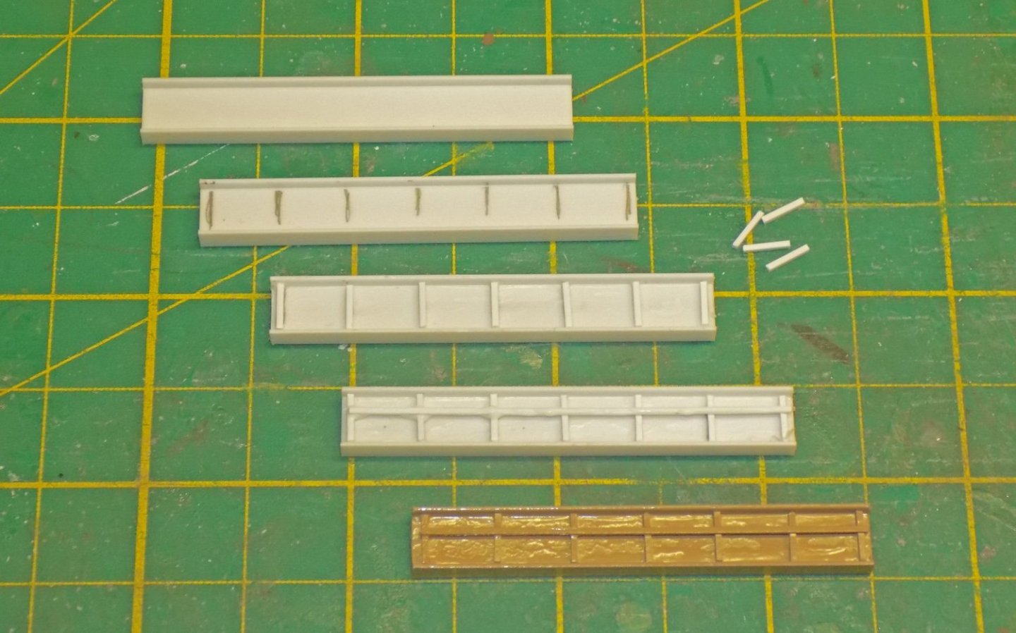
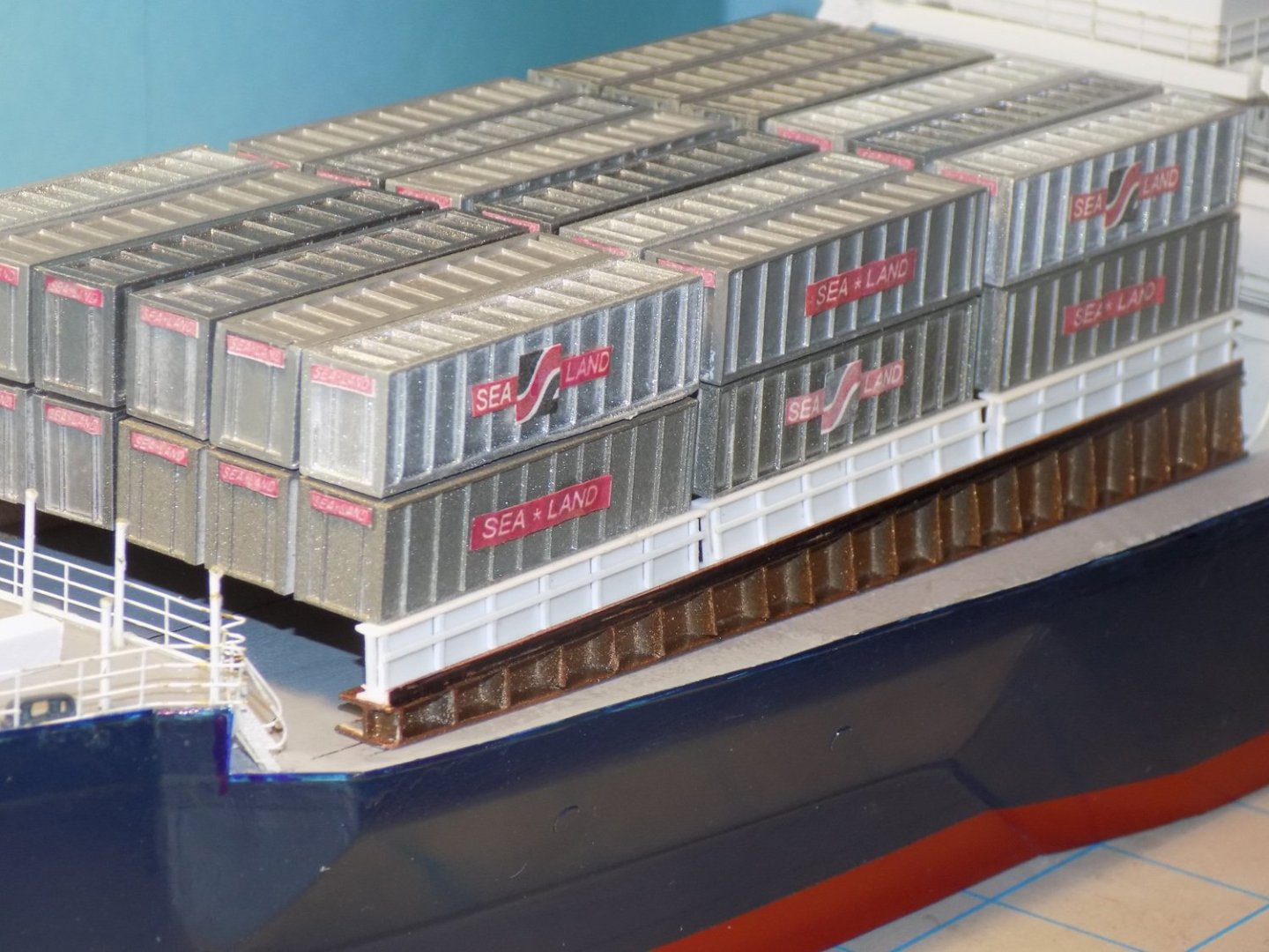
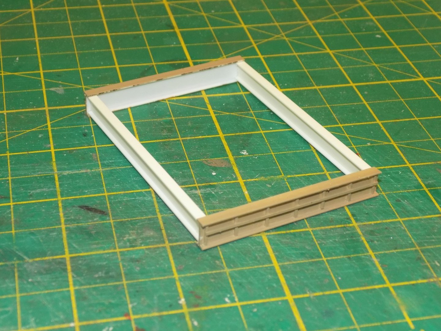
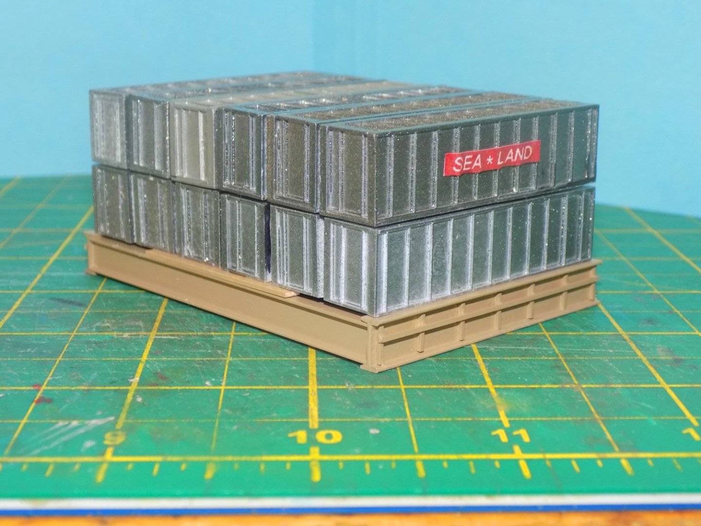
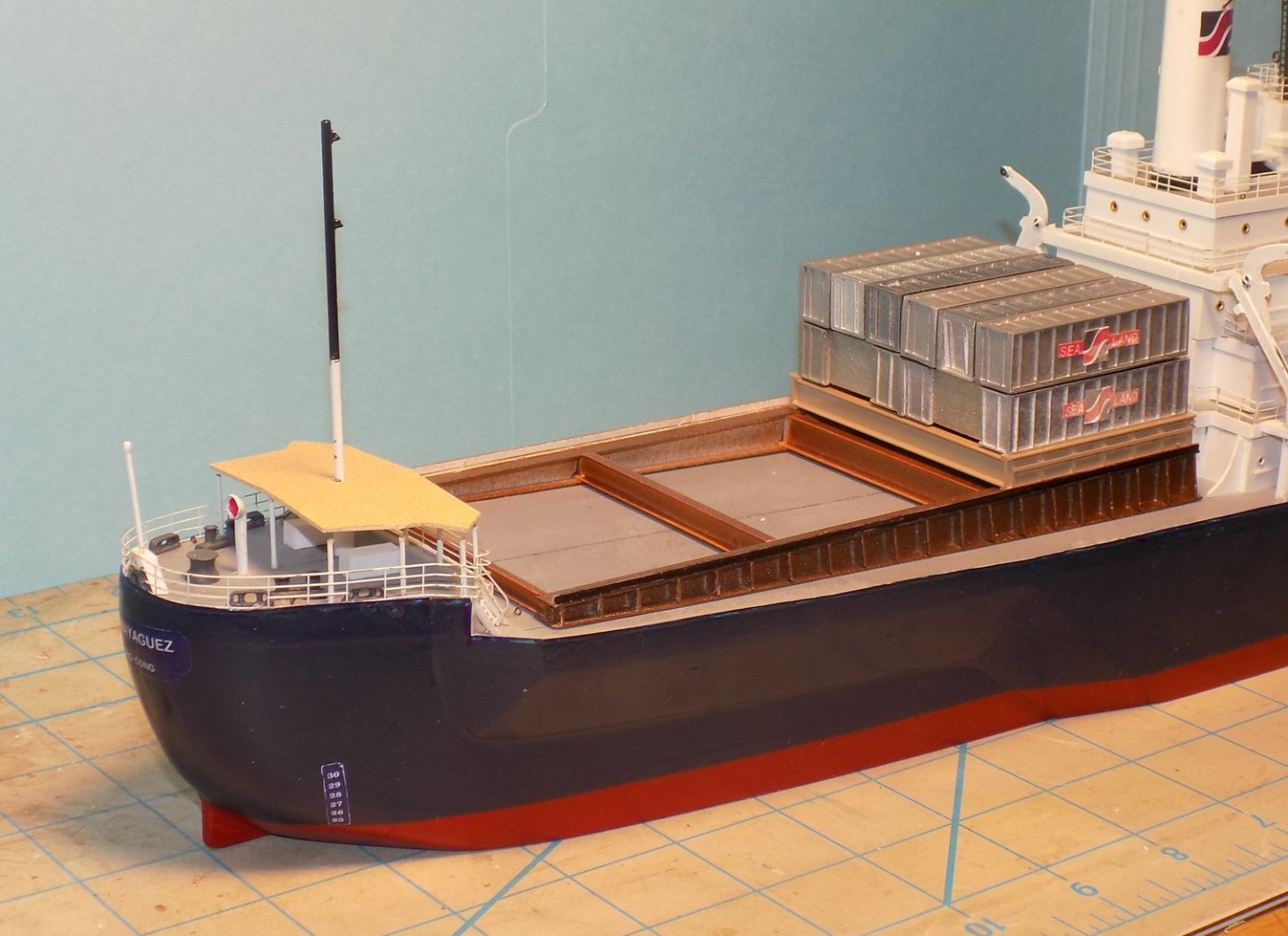
Hello again to all, and thanks for the likes of my last posting. Now that the containers had all been built and detailed, it was time to mount them to the ship. The photos show that above the curved support trestles there was a set of second trestles that supported the containers themselves. Here in this first photo you can see this ribbed piece, one for each set of containers. Above the second trestle is a retaining board (or at least that is how I interpret the photos). This first photo was taken before the piracy incident and shows that the retaining boards also had ribs along their length. Notice in this photo that was taken at the time of the incident that the retaining boards are smooth and have no ribs. I have no idea when the change was made, but since I was modeling the diorama as of the time of the event, I used smooth boards. The first step was to build the second trestle assemblies that support each set of 12 containers. Lengths of 5/8” tall I-beams that fit the look and the relative dimensions seen in the photos were cut to a length just slightly longer than a container. These then had to sit on top of the trestle supports with enough clearance to allow access to the crane guide rail. Each of the I-beams lengths was marked in pencil for 7 ribs. These were individually cut from 0.03” square strip and glued over the pencil marks. I used a very small dot of white glue on one end of the rib and put each in place. When the glue dried I went back and fed a drop of plastic cement by capillary action under the rib. A gentle press welded the rib in place. I found that white glue alone made a mess as I moved the rib into position, while using only plastic cement did not give me enough open time to fiddle the pieces into place. A horizontal reinforcing bar was added just above the halfway point and the assembly was painted in a khaki tan. I have no evidence for this color, but it sets off well from the bronze of the support trestles and the steel of the containers. To get the spacing for the lower trestles on deck I first had to put together the blocks of 12 containers that would sit on the second trestles. These blocks are in turn made up of four ‘triples’. I found that it was easiest to get consistent results if I assembled three containers onto a flat plate. I could align them against a square jig and use thin spacers between them as the glue dried. Two of these ‘triples’ were similarly attached to a larger plate with a bit larger space between them. Then the final two triples were stacked on top. Once all the blocks were made up I took three and dry fit them on top of the trestles on the aft deck. I was very pleased to see how well they fit, given the tight tolerances of the model. The outside aft corner of the trestle had to leave enough space to walk between it and the deck railing. The result is perhaps a tad narrow, but looks acceptable. Without moving anything the centerline and outer corners of the lower trestle were marked and drawn on deck. The blocks of containers were removed and each pair of second trestle pieces were joined together to form a pallet. This was done with I-beam cross-pieces that fit inside the flanges of the trestle pieces. Shim pieces were added to the cross-pieces to make up for the differing sizes of I-beam and the pallets were painted. Now a full block of containers could be attached to each pallet. In a similar manner the lower trestles were connected with I-beam cross-pieces that were sized so the trestles fit on deck exactly as marked and the pallets of containers fit exactly between the crane rails. Once everything was triple checked the trestle assemblies could now be permanently attached to the decks. The pallets were set in place on the trestles and the retaining boards added. These were painted a slightly lighter tan color than the pallets, but the difference is hard to see. Here at the bow the forwardmost block of containers was not supported on a pallet, but just on I-beams. This matches what is seen in the photos, but I have no idea why they are different. In this later photo some additional details have been added, including the guy wires for the forward mast, the railing along the side of the deck, and the fairleads and bollards for the mooring lines. The last major element to construct was the pair of rolling cranes to load and unload the containers. These will be covered in the next segment of the build. Till then, stay well. Dan


-
Hi Keith - Thanks for the compliment. The short answer to your question is - lots and lots of staring at the images and ruling out alternative solutions. As Sherlock reminds us - after you have eliminated the impossible, whatever remains, however improbable, is the truth. Dan
-
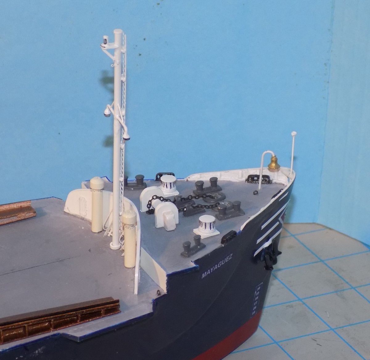
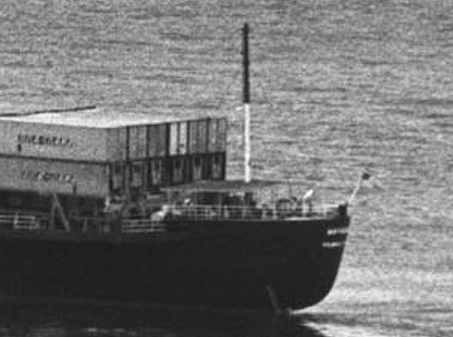
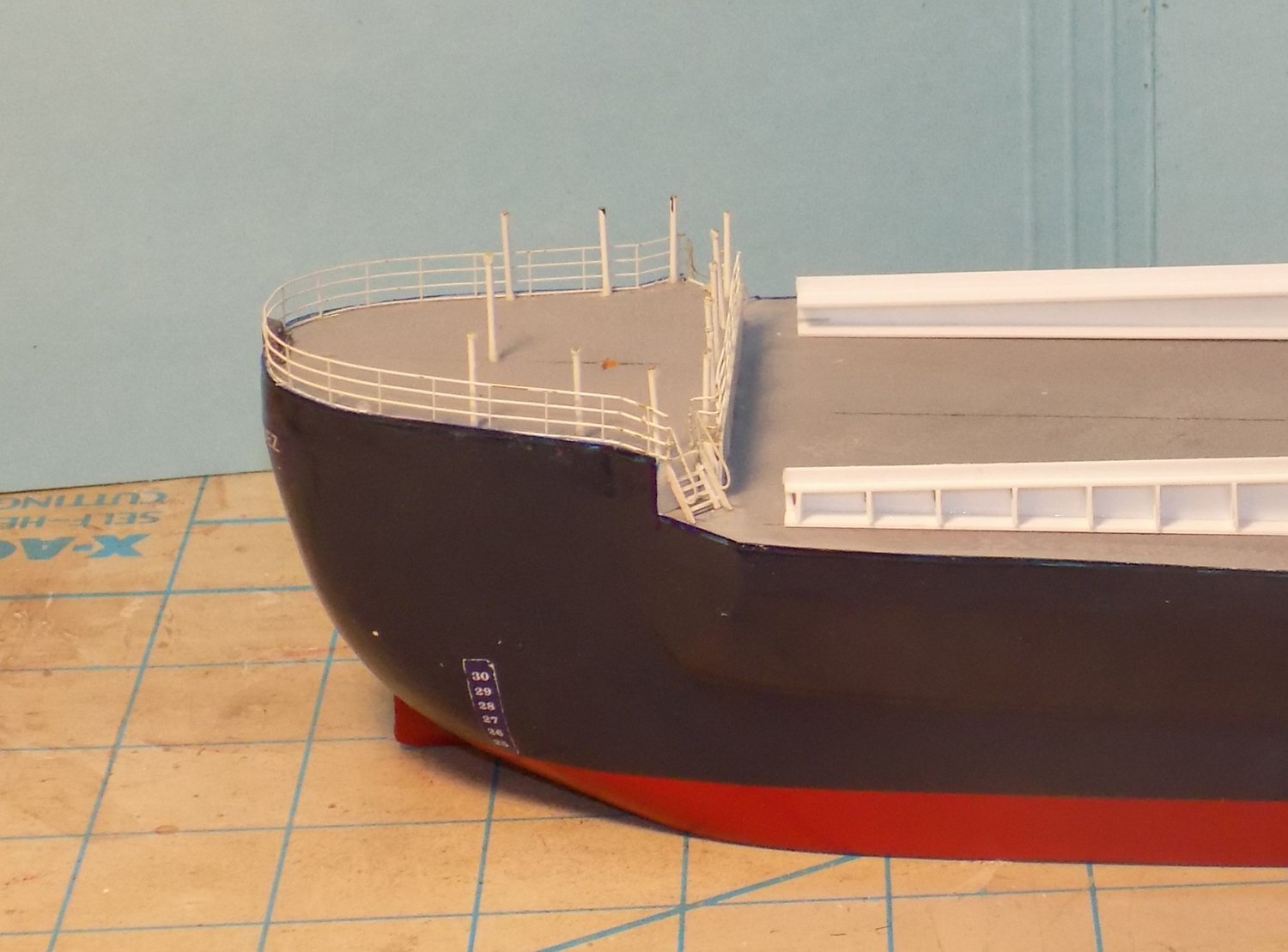
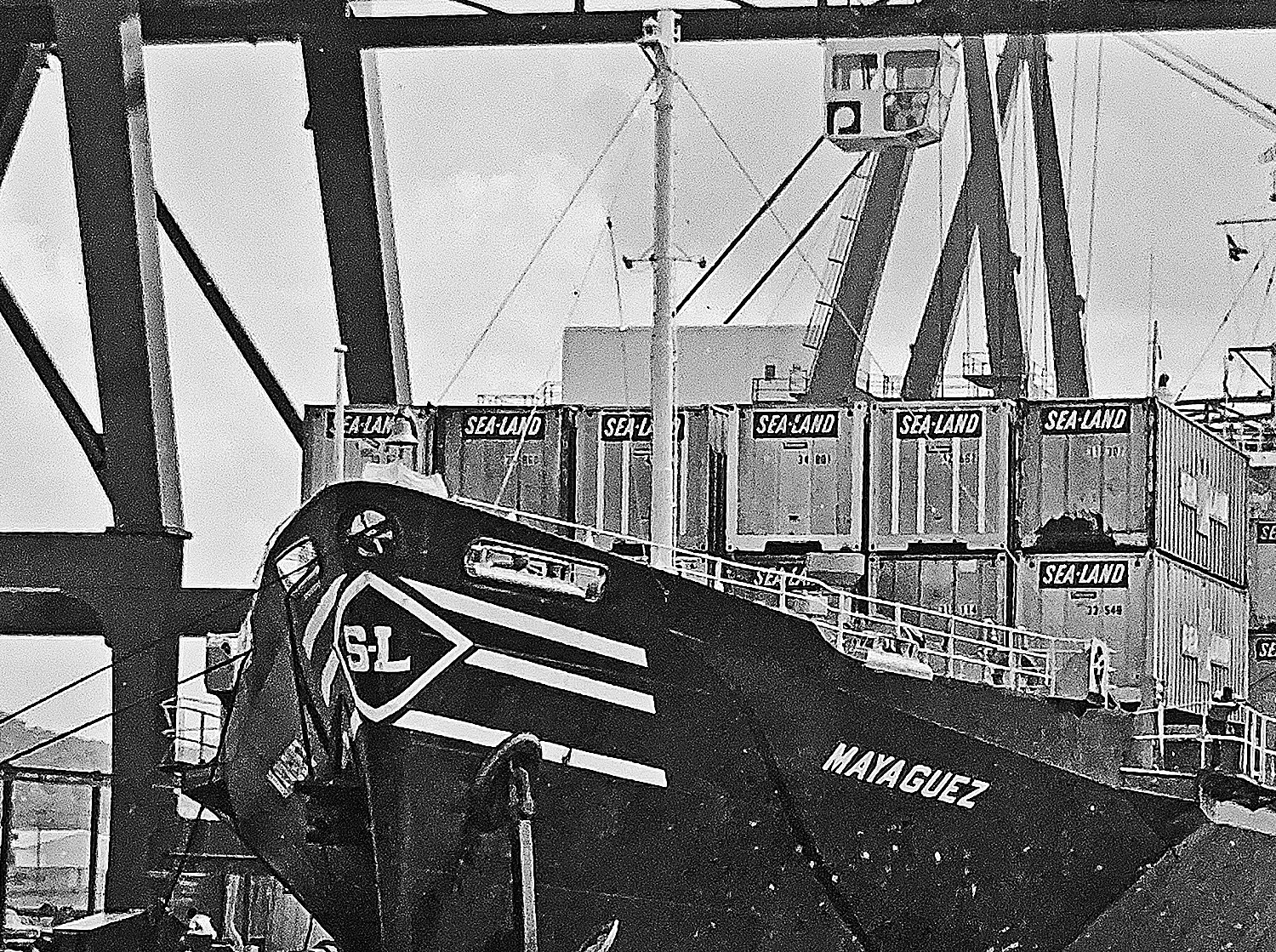
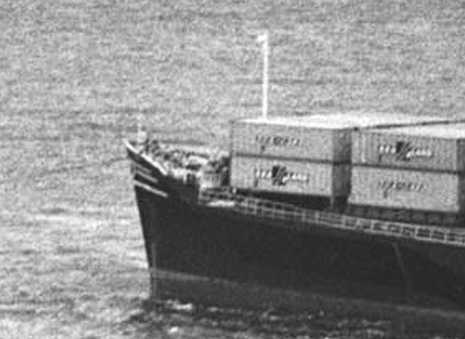
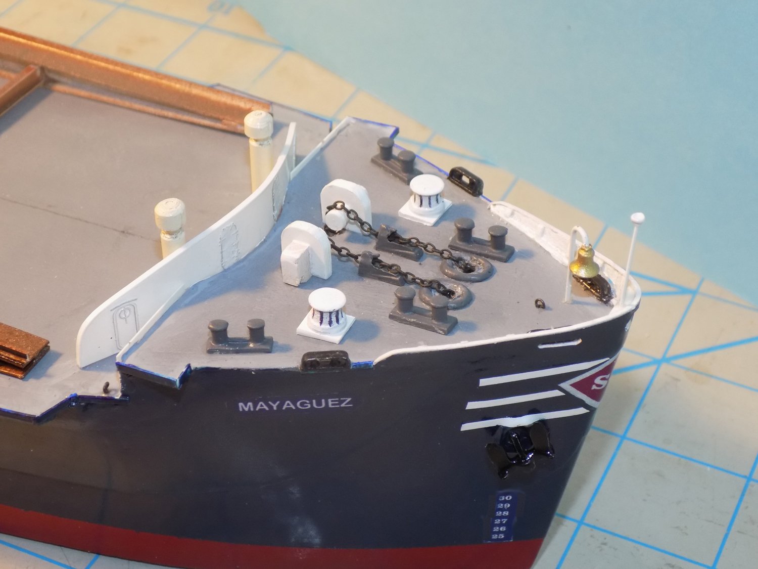
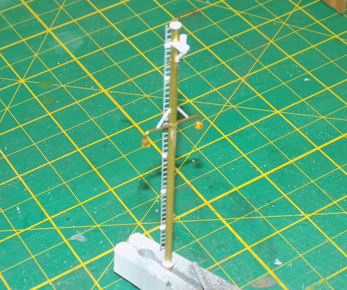
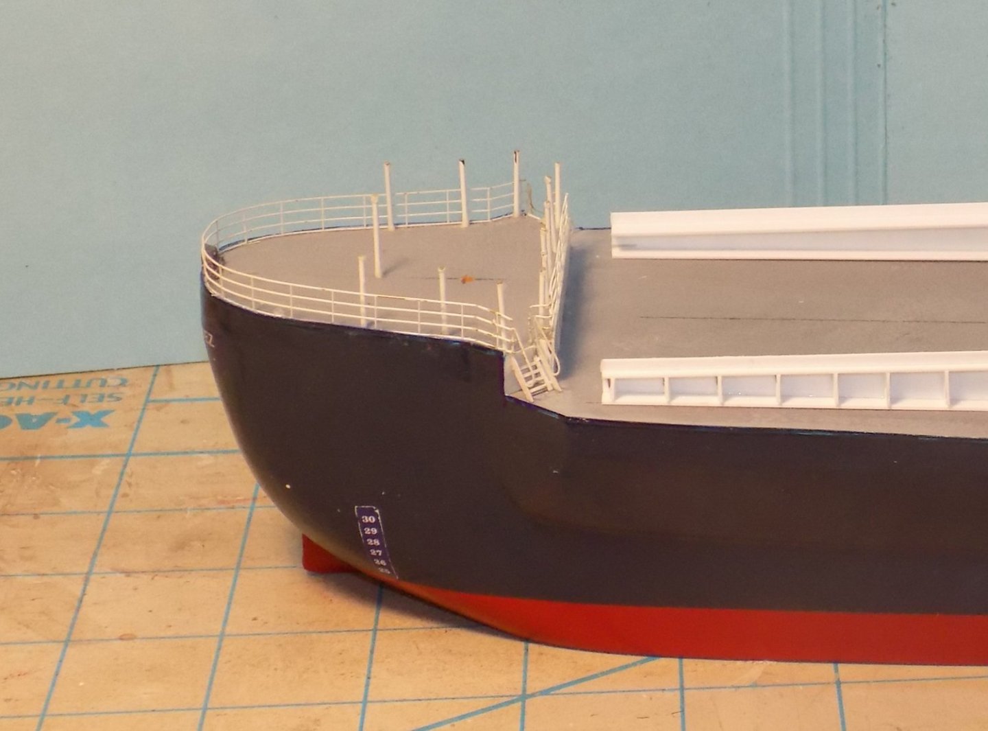
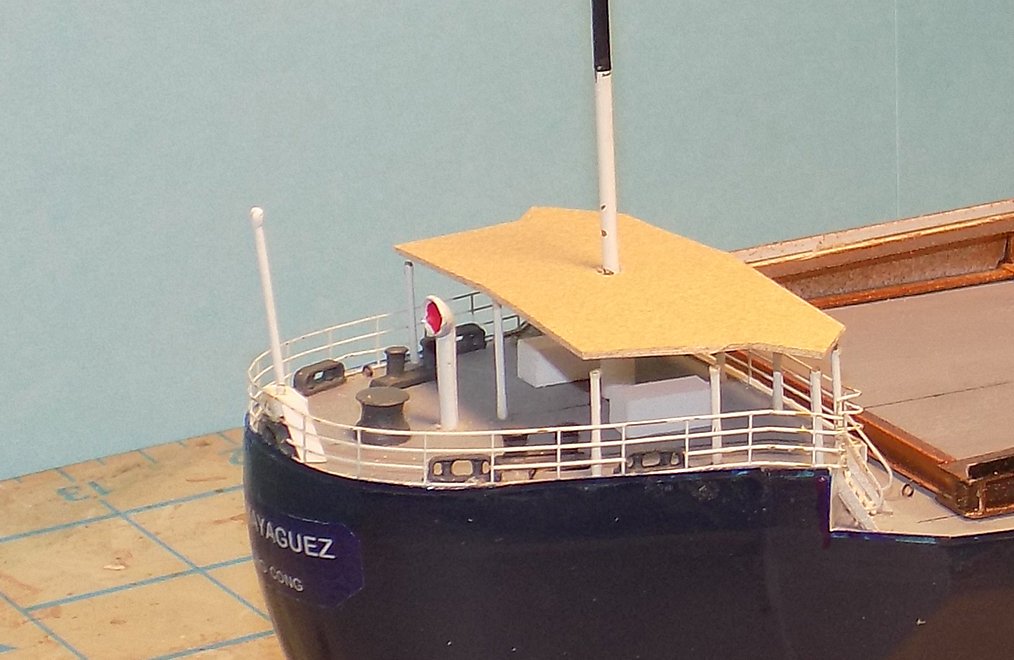
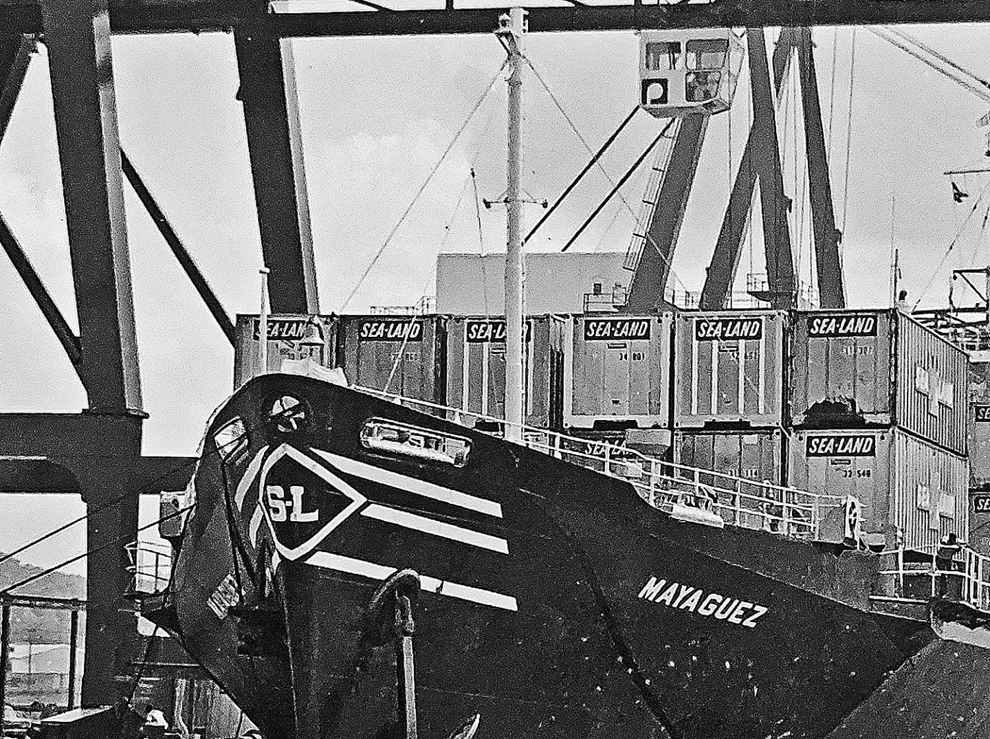
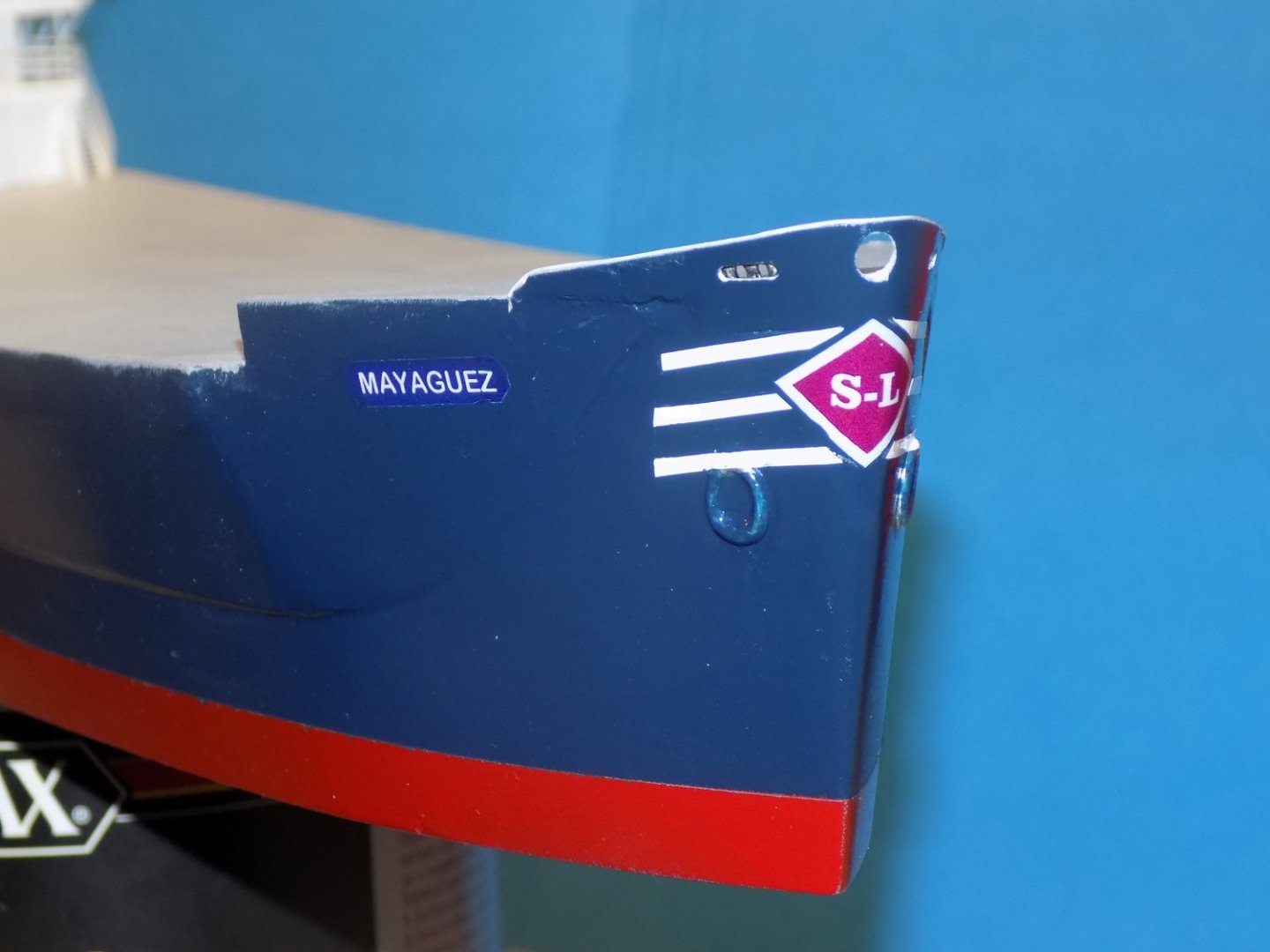
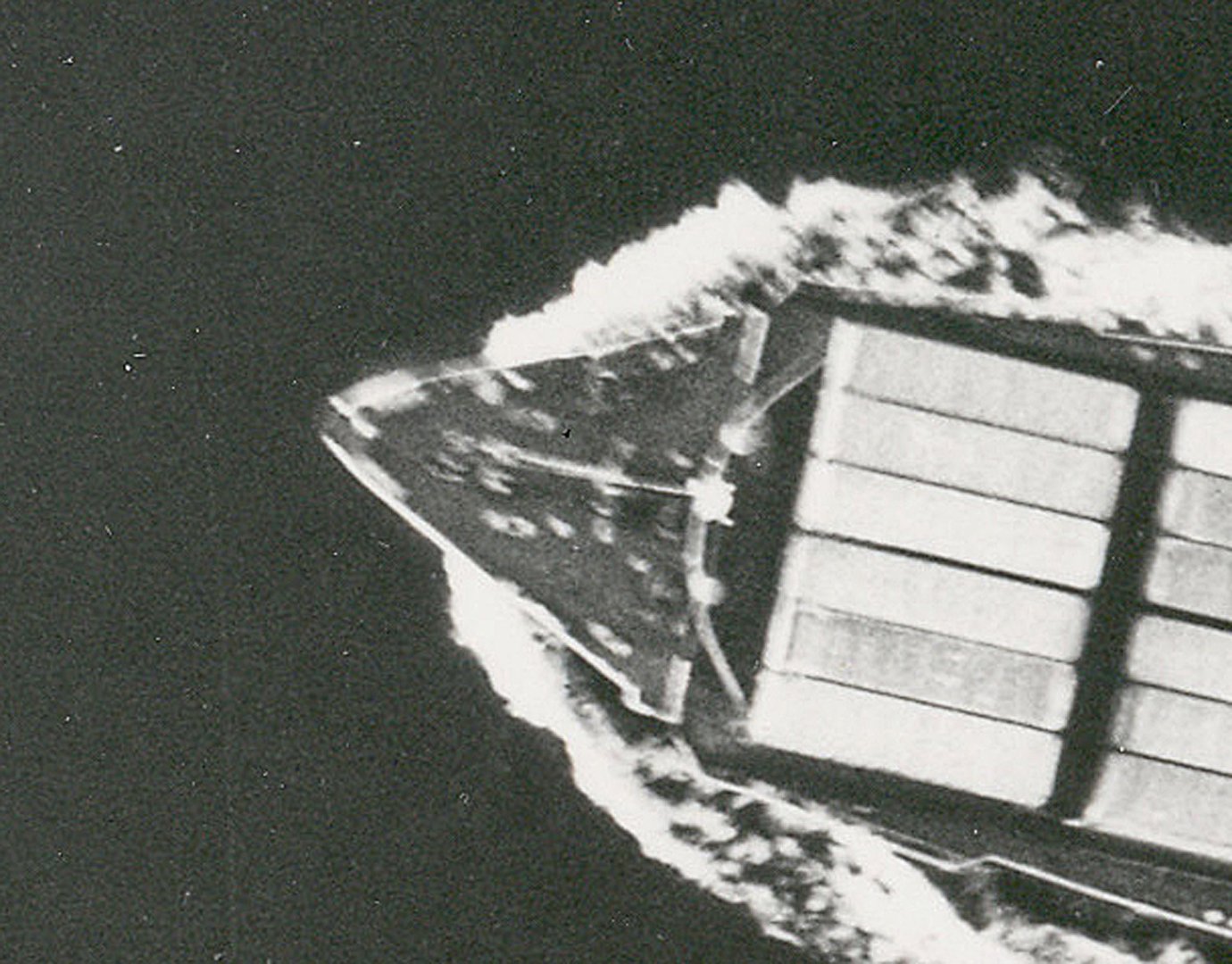
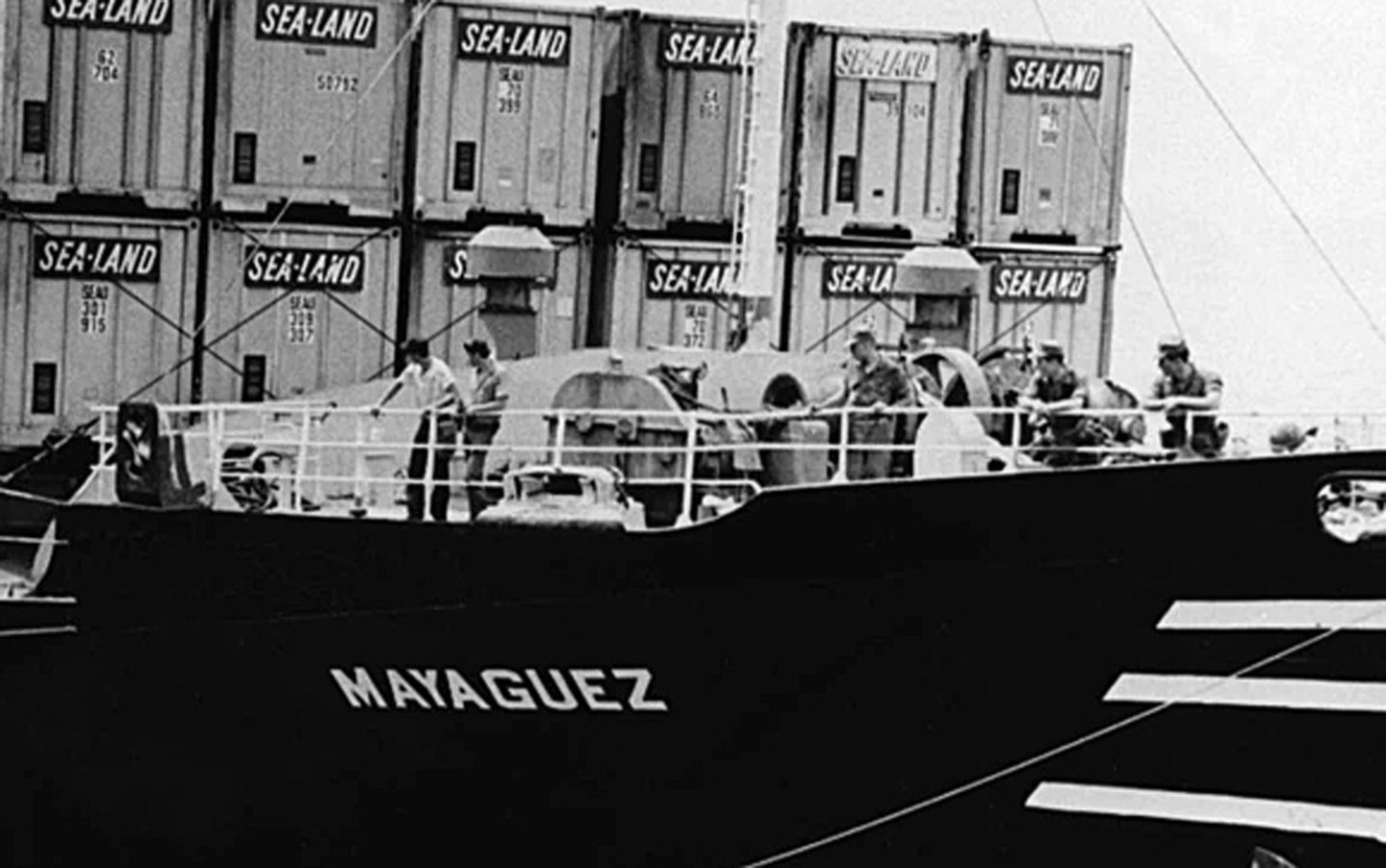
Hello again to all. My thoughts and best wishes to all who have been affected by hurricane Ian. Listening to the news reports surely puts our activities in perspective. The next portions of the model to detail were the hull areas and raised decks at the bow and stern. The exterior of the bow was well visualized in several photographs. In the one below note the hawse pipe for the anchor, the openings in the bulwarks for the fairleads, and the graphics of the ship’s name and company logo. On the model the hawse pipe was located and a cast hawse lip was attached. The center of the pipe will be drilled open at a later time for the anchor. The openings in the bulwarks were drilled open with a smaller bitt, then filed to final size and location with needle files. The ship name is a homemade decal, blue printed on white film. After attaching the white edges were painted to blend in with the hull color. The logo at the bow is also homemade. The red diamond is printed on white film which was carefully cut to form the white edging. The triple lines are also decal film individually cut to shape and applied. All the decals were sealed with clear acrylic gloss. Unfortunately there were no comparable photos of the machinery on the bow deck. Here is the best one, taken from overhead. As you can see, there is a distinct lack of detail. Others taken from various angles show even less information, although in this one I could get the height of the foremast. Each photo, no matter how blurry, could give me a tiny piece of information to add to the totality. The only one that had a clear image was taken from a height level with the deck, and although it gave me some idea of the nature of the deck machinery, the locations and sizes were still mostly guesswork. Ultimately I fell back on my experience with other working decks and built up in what I believe is a logical sequence. I started with the fairleads, which I could see and locate from the photos. Then I put on bollards to take the lines that came in through the fairleads. Then a pair of capstans were set between the bollards to haul in the lines. For the anchor machinery a pair of hawse holes were set on either side of the centerline so the anchor chain can run through a pair of chain brakes and then over the heads of a pair of large winches. The ship’s bell can actually be seen in some of the photos, so it was turned from a dowel, painted brass and installed on a painted brass rod. The fore mast as seen in the photos has a running light at the top on a small platform, a cross arm with floodlights at either end, and a ladder running to the top. It was constructed from brass tube and rod, with plastic details and a photoetched ladder. After painting it was set in place flanked by two round topped ventilators. (Yes, I realized later that it was put in backwards. It was turned around before being permanently installed. Just put it down to another senior moment.) The details of the stern raised deck are equally conjectural. Here is one of the best images that I could locate of the area. About all that can be said is that there is a mast, painted white with a black top, that comes out of a slightly curved sun shade over most of the deck. The second image is a little clearer and some bollards can be seen as well as a cowl ventilator and an ensign staff. Accordingly, I installed a railing around the perimeter of the deck and some 12 stanchions bade of brass rod that will hold up the sun shade. And here is the final deck layout. The fairleads and bollards are cast fittings from Bluejacket, as is the cowl ventilator. The sun shade is built up of a styrene sheet with a layer of parchment colored paper on top meant to simulate the canvas cover of the original. It has not been permanently attached to the stanchions as yet until the mast and its guy wires are installed. Since the deck under the sun shade could not be seen, two simple storage boxes were created and set in place. In the next segment the containers will be permanently installed on their various support structures. Until then, be well. Dan


-
Vaddoc - No need to apologize. They look great, especially for such a large scale. PS - I keep a tube of Neosporin and a pack of Band-aids near the table saw at all times. LOL Dan
-
Roter Löwe 1597 by Ondras71
shipmodel replied to Ondras71's topic in - Build logs for subjects built 1501 - 1750
Ondras - Yes. That is just what there should be. It is good to see that the whipstaff is properly modeled, when it is not often seen. Thanks for showing your work to us. Dan