shipmodel
-
Posts
941 -
Joined
-
Last visited
Content Type
Profiles
Forums
Gallery
Events
Everything posted by shipmodel
-
 Hi Marc - The hulls are looking fantastic. Looking forward to your presentation in New London. I would be hesitant to use a lacquer based finish over other paints. I have found that the solvent is very aggressive and I have had it wrinkle underlying coats, even after they have dried for weeks. Test, and test, and test again. Dan
- 2,699 replies
-
- 4
-

-
- heller
- soleil royal
- (and 9 more)
-
Hi Gary - Not sure exactly which units you are talking about, but you certainly may be right. I claim exactly no experience with HVAC systems since I never handled a lawsuit that involved them. Most of my units are my interpretations of the external appearance of what I can make out in the photos that I have, which are incomplete, not usually very detailed, and only show a snapshot of what was a 17 year long movie. Hotdog stands work for me. I believe that I can make out the word "Sabrett's" on the side of one . . . (a New York in-joke) Dan
- 238 replies
-
- 5
-
-
- leviathan
- troop ship
- (and 2 more)
-
Marc - Best of luck finding the painting in the Parker gallery. I have my fingers crossed for you. I was wondering, though, why you are choosing a verdigris color for your cannon. The green is a function of the oxidation of the bronze - - - rust! I have a hard time thinking that the officers of a first-rate king's ship would allow the sailors to slack off so much that the guns would have time to rust. If they are rusty outside, they are probably rusty inside, and that can seriously affect firing accuracy. Cannon in museums are always green because no one is cleaning or using them. I have always opted for the deep reddish gold of fresh polished bronze. Whatever choice you make, I am sure it will make the artistic statement that you want. See you soon Dan
- 2,699 replies
-
- 5
-
-
- heller
- soleil royal
- (and 9 more)
-
Marc - Sweet solution to up-weighting the guns. They will look good when blackened. Dan
- 2,699 replies
-
- 4
-
-
- heller
- soleil royal
- (and 9 more)
-
Plausible deniability - what a wonderful phrase. 😁 Dan
- 238 replies
-
- 3
-
-
- leviathan
- troop ship
- (and 2 more)
-
Yes - I believe I saw the same show. It changed my view of that little bit of history. As for ventilation, it was always considered a serious issue. It is reported that the Vaterland had 113 ventilation blowers, 51 exhaust and 62 supply, and then there were the ones added during the conversion to the troop ship. The importance of breathing is obvious. From the history of the ship's Medical Department written by its head Dr. Dunlap: ". . . quotative examinations of the air in the troop spaces were made at different hours both day and night to determine the temperature, humidity, and amount of carbon dioxide in these places; these observations were made the subjects of various reports and resulted in the installation of new ventilating systems and correction of those already in operation . . ." No wonder I can't figure out which ones went where at any specific time. Dan
- 238 replies
-
- 7
-
-
- leviathan
- troop ship
- (and 2 more)
-
Hi Keith - yes, they had lots of health concerns. On one crossing there were over 14,000 soldiers, sailors and nurses aboard. Without major ventilation they could have exhausted the available oxygen pretty quickly. Whatever their concerns, they were not enough, and almost 1,000 soldiers died of influenza during another crossing. Dan
- 238 replies
-
- 6
-
-
- leviathan
- troop ship
- (and 2 more)
-
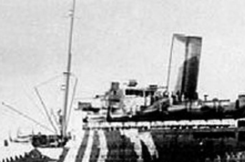
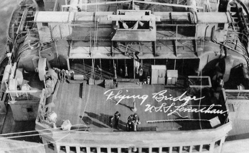
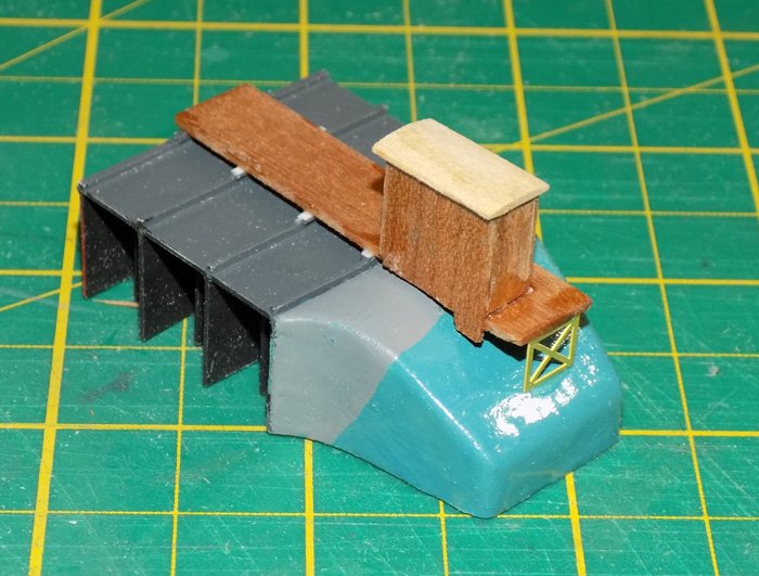
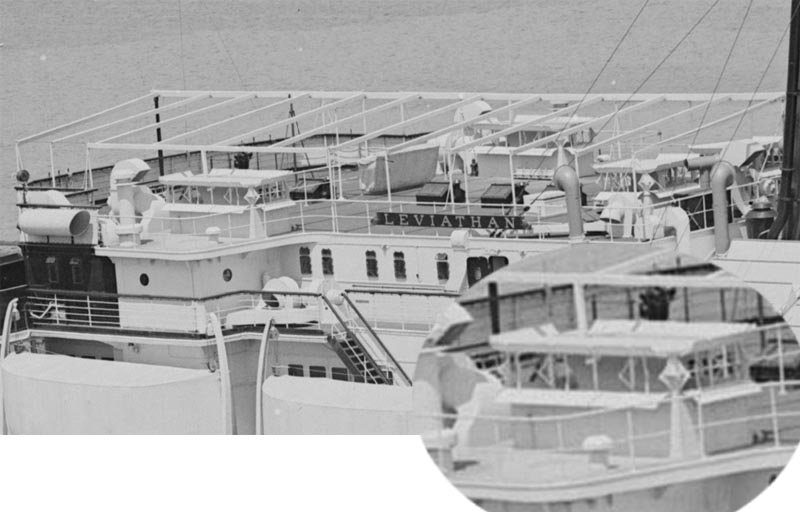
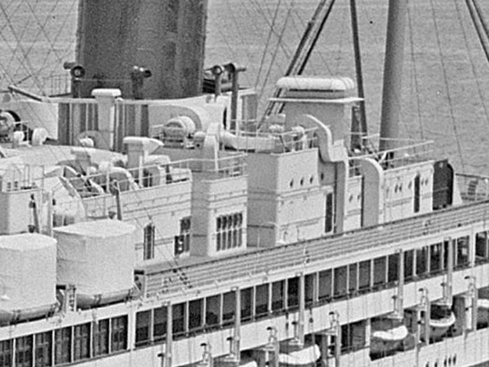
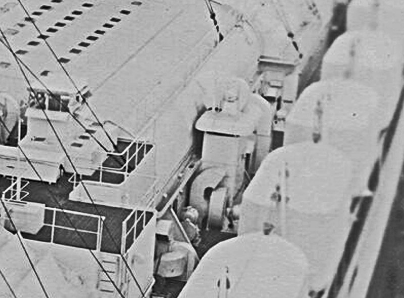
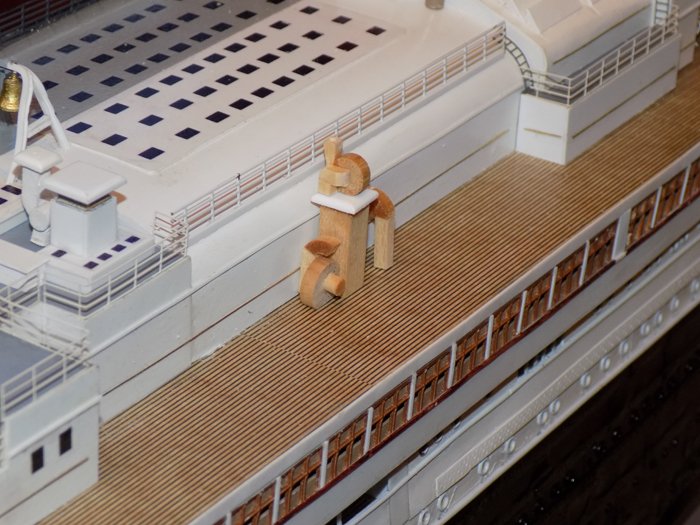
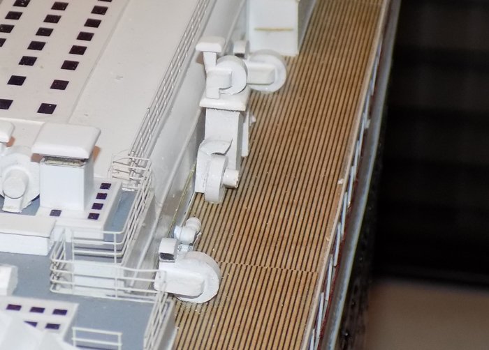
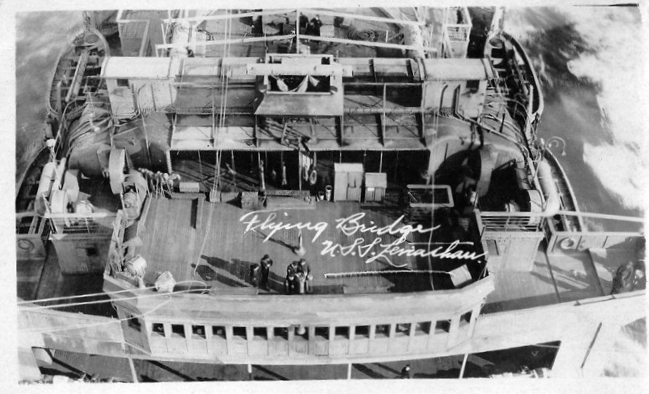
Hi all, and thanks - Carl - in today's world I guess you would be right, but the vertical dividers seem to be what I am seeing in the photos. Mark - Yes, I skimped a tiny bit on the access hatch. There is a suggestion of a two-step stairway up the back center in the detail photo. But the space is only 3mm tall and then I would have to cut the steps in half!! I chose to believe that the hatch was on the liner side and did not have to be modeled. That's my story and I'm sticking to it. The rangefinder will have to be tall enough to look over the walls of the platform, which are scale 6 feet high. That would not be a problem on top of a sturdy column. It is probably housed in that long, square box that seems to sit athwartships on top of the walls. Is that a protective cover that was removed during use? Do I show it or show the rangefinder exposed? How do I model it so it tells a story? Questions for a later time. As for the height, there are no plans, but here is the photo taken closest to horizontal. It has fairly high resolution for such a long range shot, but this is as much as it could be enlarged before it pixillated. Some artistic license did have to be used.
- 238 replies
-
- 6
-
-
- leviathan
- troop ship
- (and 2 more)
-
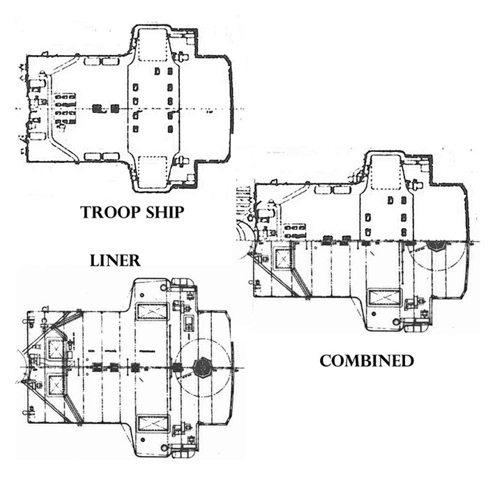
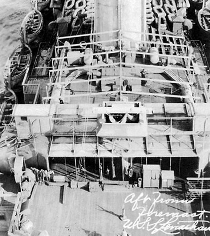
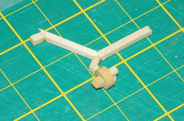
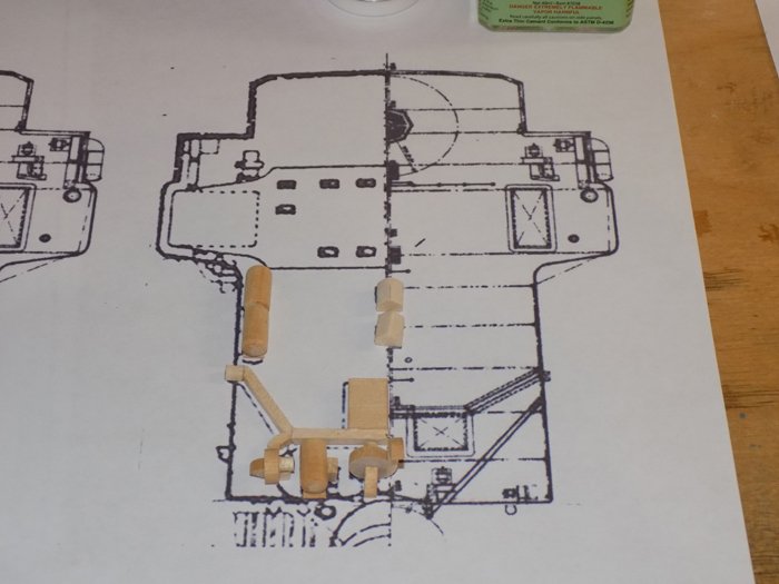
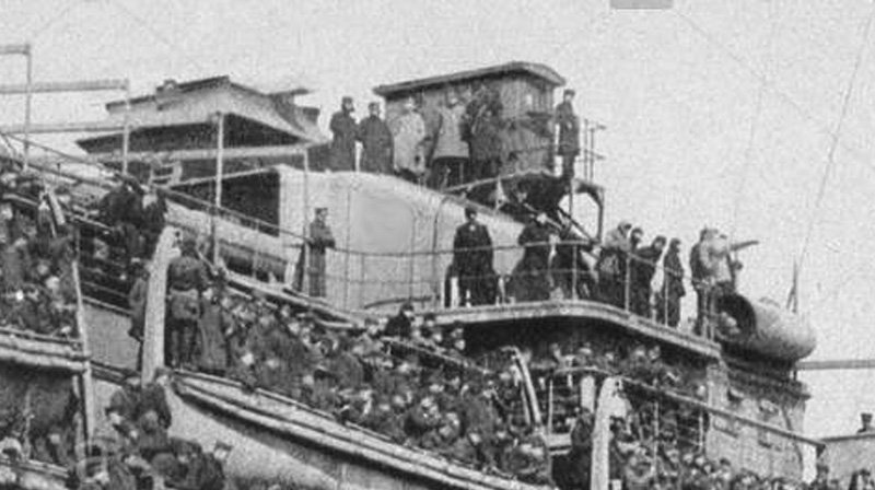
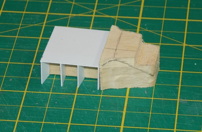
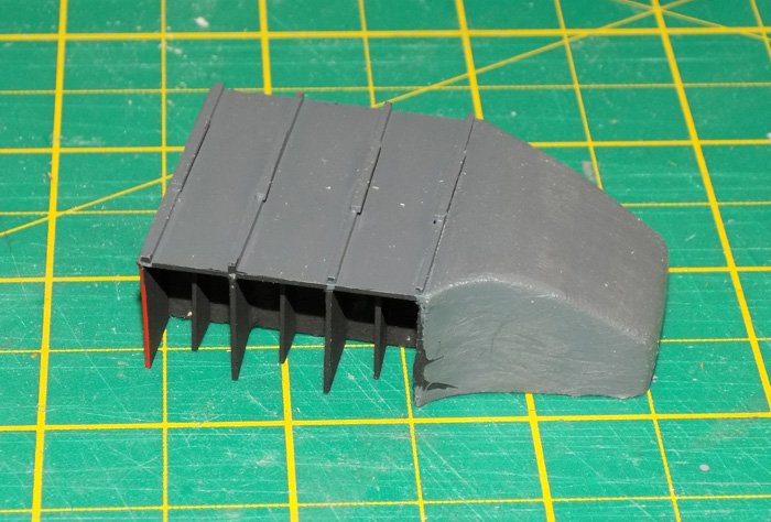
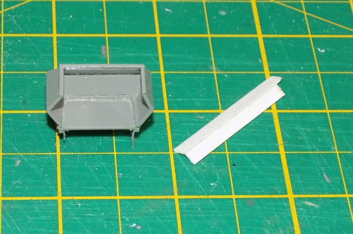
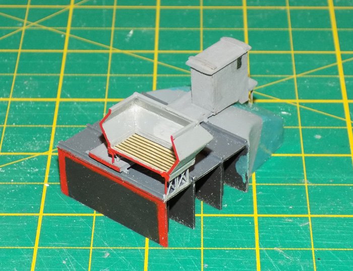
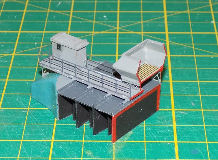
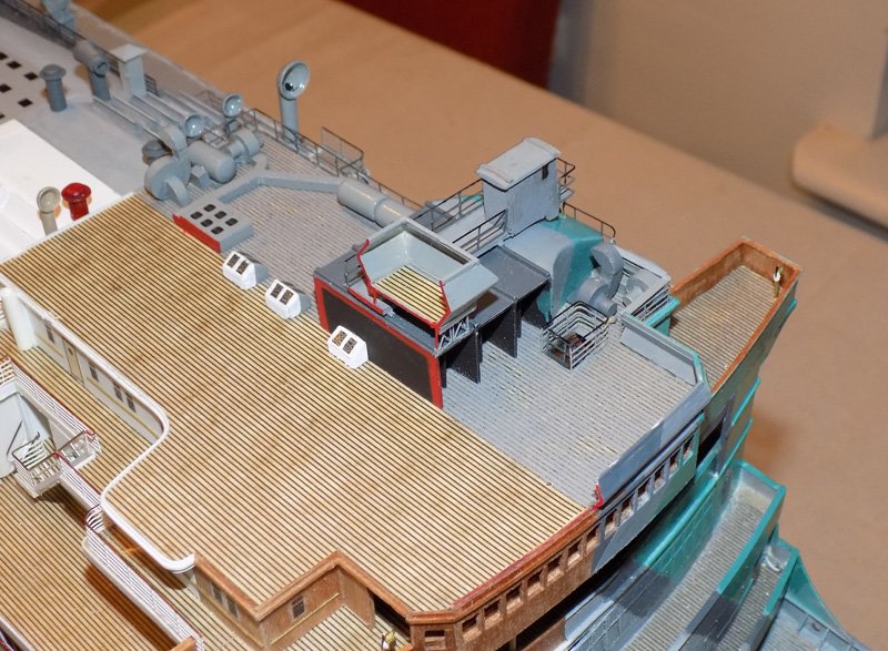
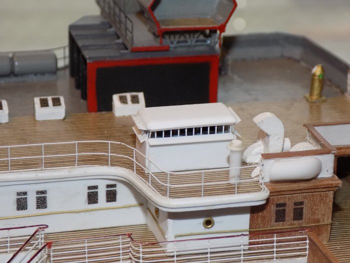
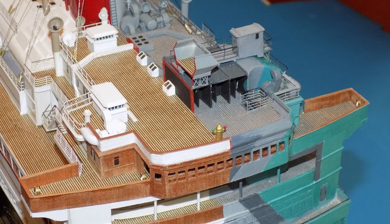
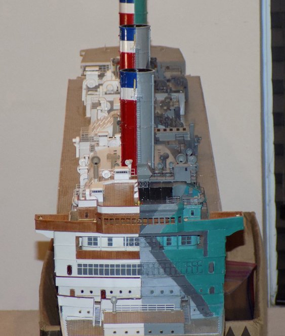
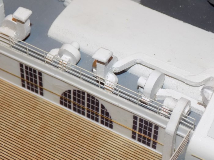
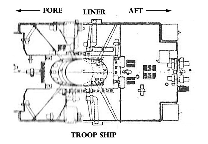
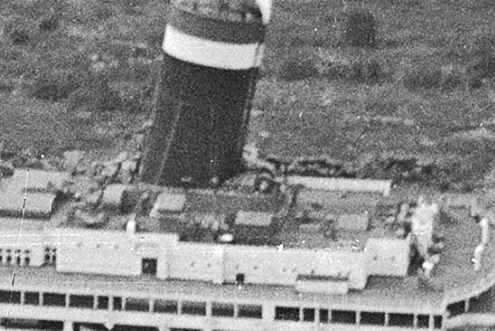
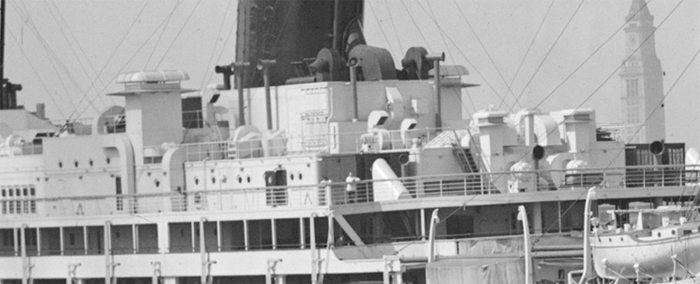
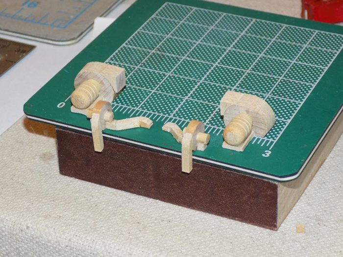
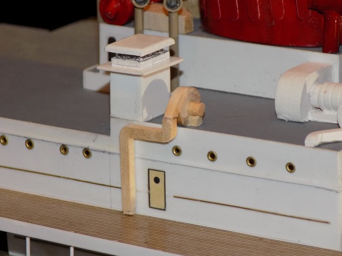
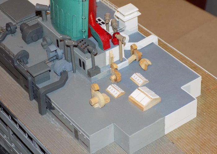
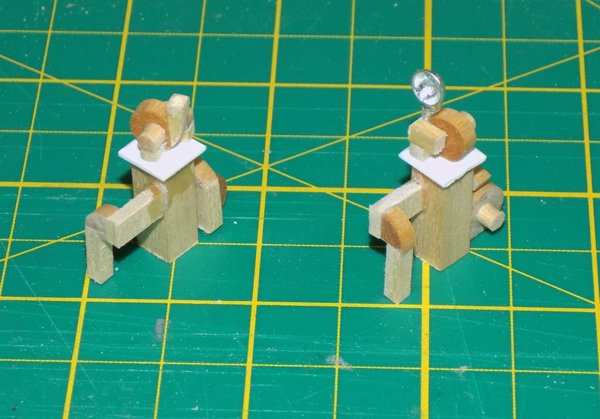
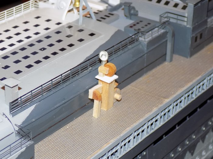
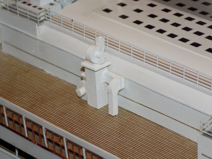
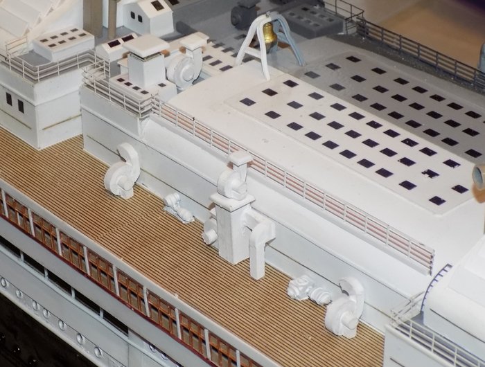
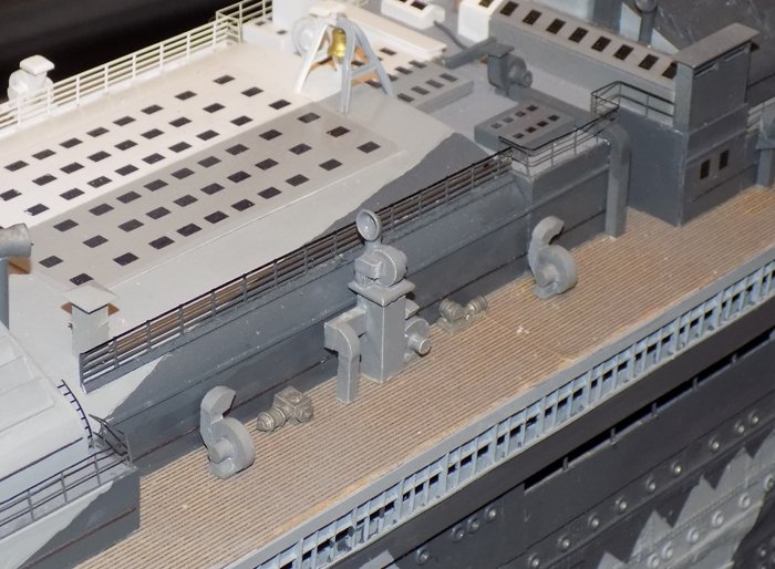
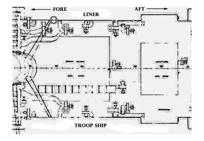
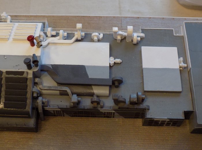
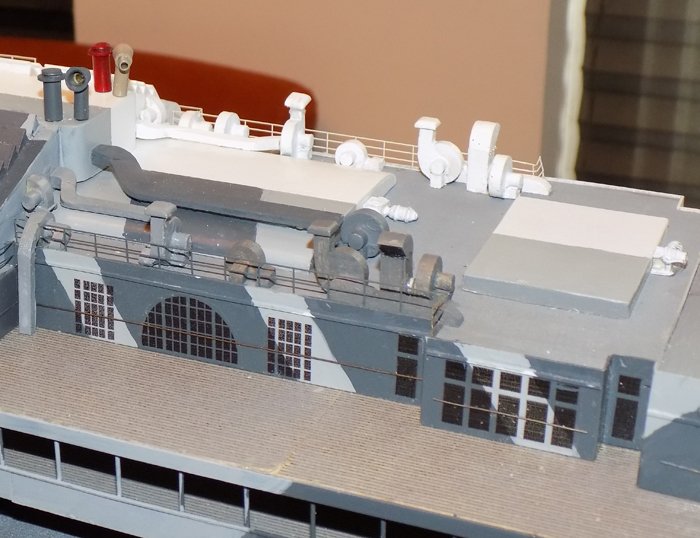
Build log 16 – Leviathan Yes, Keith, it is Sunday and here is another installment. Glad you are enjoying them. Thanks to all for the compliments and comments. A lot of the fun of doing these logs are the interactions between all the great friends across the globe. We move on now to the top of the bridge deck. Here the structural revisions from the troop ship to the liner are the greatest. Mostly this has to do with the reduction in ventilation systems and their upgrades. The plans for the area were abstracted from separate plans of both the troop ship and the liner. I then halved them and combined the halves to make one plan for the model. I started with the troop ship side. I located a photo taken from the foremast lookout platform which shows the area, especially the large air intake structure and the strange square construction on top. It also shows most of the deck details on the aft portion of the deck. Most of the details in this area are similar to the blowers and ductwork which were made for other areas, and the techniques used were the same. In addition to the blowers and ducts there are several cylindrical tanks for liquids, although I do not know what the fluids were. A large flat skylight will have to be cut in half, but two smaller ones exist in both incarnations, so they were made in full. In this detail photo, probably taken while she was being converted to the troop ship, the entire intake trunk can be seen, along with the two lookout houses to either side, and that square construction in the center. I had no notion of what this was, until I read the official history of the ship. It turns out that this is a platform for a large rangefinder for the 6 inch guns that the ship carried. I found drawings of several types and will probably try to make something convincing later on. From below the platforms and railings of the lookout sheds can be seen, as well as the strange angled sides of the rangefinder house. The intake structure started with a central wooden block for the body of the intake trunk, with thin vertical separators as seen in the photos. The curved end was carved from a block of basswood. After priming in dark grey it was evident that the intake ports were too simple and looked wrong. I added shallower dividers and painted the interiors flat black, which improved things a lot. The lookout house and its walkway were built up out of cherry veneer with a rounded basswood top and an “X” frame PE support taken from from the spares box. Here they are being test fit. The rangefinder house was pieced together with styrene cut and fit. I thought that the angled sides would be more of a problem, but I sanded bevels into wide strips of plastic and welded them together with liquid cement. The three required pieces were cut off and the mating corners beveled until they formed an open rectangle. Cap pieces top and bottom were added, then mated to the solid floor. A paper floor was cut and fit inside, with PE supports cut and fit underneath. The ‘cut’ edges were painted red to show the line of cleavage. Note to self – clean up the camo paint inside the intake. Damn, these digital closeups show everything! Viewed from aft, the walkway and railing can be better seen. Here is the completed troop ship flying bridge. Note that the railing around the forward edge is solid and has the same ‘vee’ shape as the rangefinder house. The liner side is dominated by white fixtures, including four large rectangular features which I take to be air intakes. These would not have to be be so large since the liner had a greatly reduced population. They look to have solid bases, an open middle intake section with thin stanchions that support the roof. There are shutters all around that could close off the opening in foul weather. I would love to know if my interpretation is correct. They were built up with a sheathed basswood base, a middle section with an internal support and PE ladders turned sideways to represent the stanchions. Tiny shutters of .010” plastic were cut and delicately glued in place. Here is the combined area. On the liner side the railing is not solid, but is strong 4-bar PE with a wooden caprail and a paper strip to simulate the canvas wind screen. I also added a Bluejacket binnacle along the centerline. There is some navigational device there in one of the photos, but I could not make out which it was, so this is a bit of a guess. Lastly, the centerline shot. Next week is Passover, so I probably will not get to put together a post. So a very Happy Pesach to all my tribe, and Happy Easter or other spring festival of your choice to everyone else! Dan 14.psd
- 238 replies
-
- 18
-
-
- leviathan
- troop ship
- (and 2 more)
-
Hi Gary - Followed your post back to your log and was amazed at your realism. Bravo to you. Wherever the techniques came from you have mastered them beautifully. Now if you can come over and weather the Leviathan, I would be ever so grateful . . . 😉 I've pulled up a chair in the back. Dan
-
Hi John - Well spotted. The first photo that I used was taken from an angle that makes it seem like the short duct is not even present. It is, but with the crowded area around the blower, and having to mate up that duct with the longer one coming off the curved roof led me to skimp a bit on the detail of that short duct. I may have been a bit tired as well. Here is a better view. Better, but not perfect.
- 238 replies
-
- 13
-
-
- leviathan
- troop ship
- (and 2 more)
-
OK - I guess we are not working with a metal sheet held on by tacks. That brings me back to square one, where I still do not understand the reason for all those nails, much less how they penetrate through the layers of the lid. Thanks for the new information. Dan
- 2,699 replies
-
- 2
-
-
- heller
- soleil royal
- (and 9 more)
-
I didn't explain myself well. I don't think the metal would have been copper, but some metal that would have polished up well. It was only the method of tacking a thin metal sheet with a lot of flat-headed nails that I was comparing. The Spanish were doing this with lead sheets for their ships in the 1500s, the Romans much earlier and even the Egyptians had been working copper. By the 16th century the European armorers were making plate armor on a regular basis. Look up a History Channel show about the Greenwich steel armor that was made for Henry VIII in 1511. If it is the lid liner, what would it have been made of?
- 2,699 replies
-
- 2
-
-
- heller
- soleil royal
- (and 9 more)
-
Marc - Thanks for the picture of the Vasa. This is primary evidence that can be relied on. It clearly shows all those nail heads with a thickly raised carving, just as you have modeled it. But in the photo I think I am seeing that these nails do not attach the two layers of thick planking together, but are tacks holding on a flat metal sheet. This is similar to how copper sheets were attached to the hull in later years. I can imagine that when the lids were fully lifted the sun would reflect beautifully off the polished surface with a golden lion in the center. This solves the problem of compression or weakening of the lid itself and gives a logical reason for the look of the thing. That clears it up for me, if my interpretation is correct. Dan
- 2,699 replies
-
- 2
-
-
- heller
- soleil royal
- (and 9 more)
-
Hi Marc, Heinrich - Can you answer a question that I have had for a while, ever since seeing an illustration of French gunport lids with all those nails. Were there really that many, or has there been some artistic license that exaggerates this detail? With so many nails the wood would have to compress quite a bit to allow for the size of the shanks. If you drill them out, you create a line of perforations that will risk splitting along the grain. What am I missing? Dan
- 2,699 replies
-
- 4
-
-
- heller
- soleil royal
- (and 9 more)
-
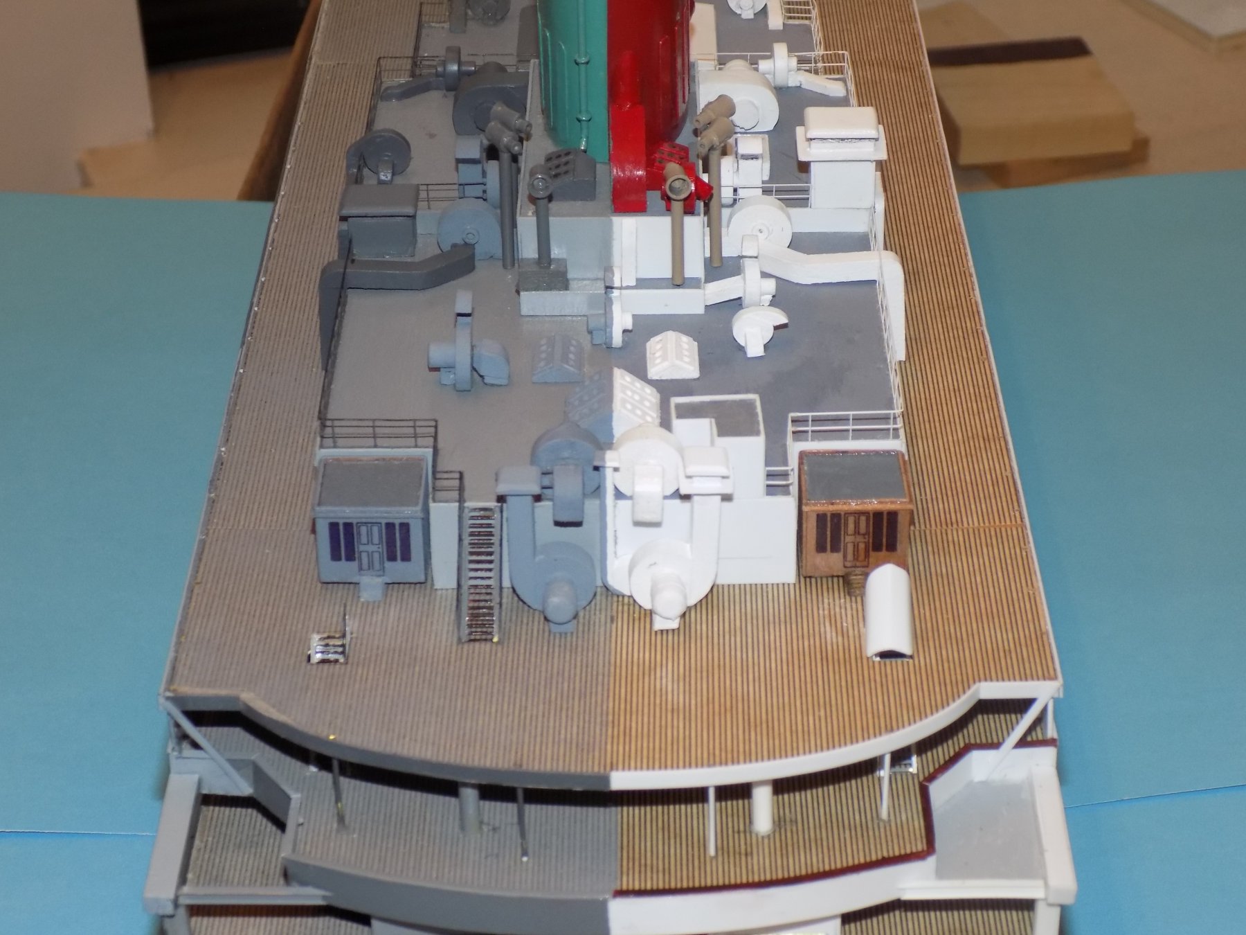
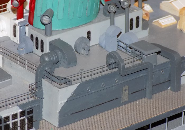
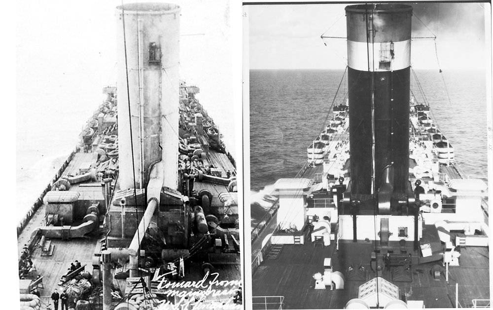
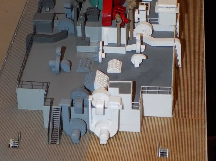
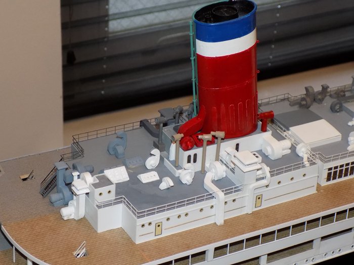
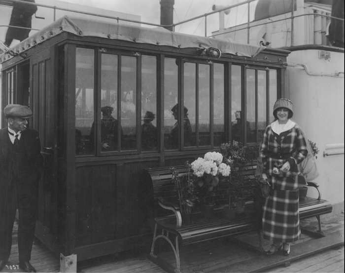
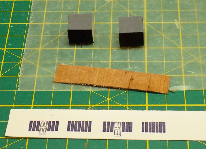
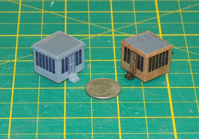
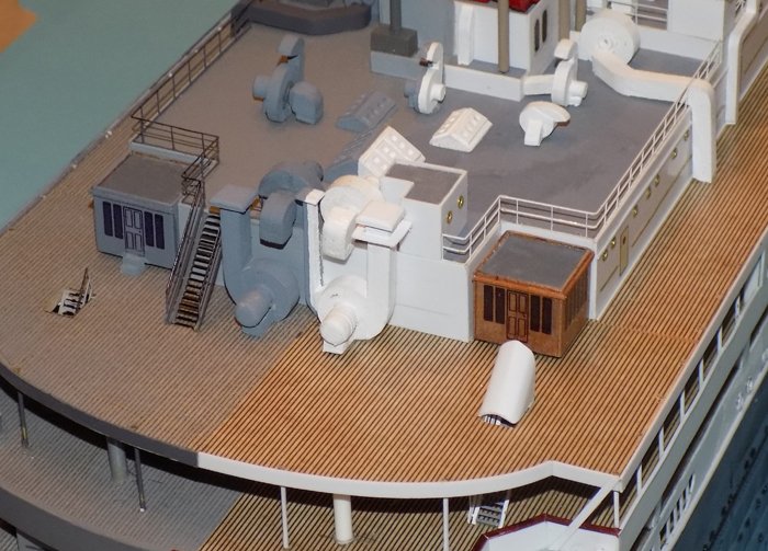
And here is part 2 The area around the third funnel and aft of it was difficult to make out and I am still not completely sure that I got it right. Here is the plan. But careful examination of photos reveals a number of differences, not only with the plan, but with each other. I took what I was certain of, and made my best guess as to the rest. One of the things I was most certain of were the two largest blowers on the ship, which connected directly to the side of the funnel platform. Their motors were large enough that I turned them in the drill press and added three grooves as decoration. A number of the blowers had ducts that angled across the roof of the deckhouses and came down the sides. Ducts were led as seen in the photos, even if I did not understand where they were going or why they had so many bends. Here is the liner side of the area, as well as the top of the funnel platform. At the back of the funnel there is a large round pipe that feeds into a square curved duct. Some of the photos that determined that shape will be coming up later. Here is the port side in shades of grey. The last pieces to put on before leaving an area are the railings. They tell me not to mess around any more without a very good reason. I was lucky to find these two photos taken from the same viewpoint of the deck house area behind the last funnel. From the troop ship to the liner the ventilation towers grow taller, ducts come and go, and the duct from the funnel loses a large horizontal pipe. This pipe is to starboard of the centerline, so in this peculiar format, it will not be modeled at all. The duct was built up and painted red to match the liner funnel since it was entirely on the starboard side of the centerline. However, it really stood out when viewed from port, so I fudged things a bit. I moved the duct slightly to port until it just touched the centerline. Then I painted that face to match the blue-green of the camouflage. On the roof of the deckhouse I made up the several sizes of blowers and skylights that I could see in the photos. At the aft end of the deckhouse are four very large blowers, two on the roof and two standing on the deck below. Between them is a small blower with a tall vertical duct that rises exactly on the centerline and had to be painted down the middle. Practice, perhaps, for the masts to come. On the starboard side is an ‘L’ shaped room fitted out with some portholes and a door. A number of lines from the antenna array lead to it, so I suppose that it is the radio shack. On the port side only a stairway leads down to the deck below. Here is the area of the third funnel all fitted out. Almost finished. It just needs the small houses that fill the notches in the aft end of the deck house In the Vaterland these were wooden sheds that stood on legs a bit off the deck. The starboard one was the florist shop and had many windows. The port one was the dog kennel. They remained during the war and for a while afterwards on the liner, but had been removed in some other photos taken later in her civilian career. I made them up from cubes of basswood set on small styrene feet. They were both sheathed in cherry veneer with window and door decals made up and printed on clear film. After a thin molding was added to the top of both, the troop ship one was painted and the decals applied. I think they give this area a nice visual grace note that would be missed if I were modeling the later configuration. The rounded fitting aft of the shed is a test piece for the hoods over the stairheads. Like the sheds they come and go, but I think I will add them if I can. Finally, the obligatory ‘here’s looking up your old centerline’ shot. Next, the roof of the bridge deckhouse, with the huge ventilator, the lookout house, and the rangefinder platform cut right in half. Till then, be well. Dan

- 238 replies
-
- 21
-
-
- leviathan
- troop ship
- (and 2 more)
-
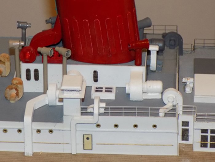
Hi again to all who are following along with this journey, and thanks for the positive responses. I missed a post last week, so this one is longer to make up. It has a lot of pictures, so the system has made me break it into two parts. After fitting out the top of the deck house area between the first two funnels, I added the machinery which was alongside the deck house. As seen in the photo, there is a large unit in the middle, with smaller ones fore and aft. Unfortunately, this is the best photo of those elements, and the white-on-white paint makes it hard to see what is really going on. After studying that and other photos, and taking into account the recent discussion and photo of exhaust blowers, I made my best guess as to the construction of the large central unit. The one for the liner is on the left, with a small blower sitting on a large duct. The troop ship is the same, but with a small cowl vent intake. It sits here for the liner And here for the troop ship After painting, they were set in place, but not attached, so they could be moved to balance the other units in the same area. I also could see where a little more sanding of rough edges was needed. The two smaller blowers were made up as usual, while the two small engines are Bluejacket castings that were modified to more closely match the photos. I also decided to put a cap on the top duct. I realized that ducts without caps are seen only on the Vaterland. Here is how that area turned out, which can be compared to the first photo in this segment. It is close enough for government work, and since this is for the government, I think it will do. Here are the blowers and engines for the troop ship. I used a contrasting shade of grey so they would stand out for the viewer, but I may yet match them to the background and let their shapes alone set them off. Aft of the middle funnel there are a gaggle of blowers and a flock of ducts to be puzzled out. Here is the plan of the area. Although there are similarities, there are quite a few differences from side to side. The photos confirm that this lack of symmetry was present at all times in her life, so I pieced the machines together and matched them to the known information and came up with this. And here it is from a lower angle. End of part 1 Dan
- 238 replies
-
- 15
-
-
- leviathan
- troop ship
- (and 2 more)
-
Hi Keith - I'm coming into this a bit late, and the suggestions that you have already are good ones. Here is another - To follow up on Eberhard's suggestion, if the surface is to be painted, you could use a short section of 8mm brass tube slid into the hole. Fill, file smooth and paint and you will have a very clean and perfectly circular edge. You can then slide a telescoping piece of tube into the first tube with a small setback as in the photo to represent the framing of the porthole. Whatever you choose, she is looking sweet and clean. Dan
-
Tom - Congratulations! An excellent model and a better cabinet. Looking forward to your next project. Dan
- 1,354 replies
-
- 3
-
-
- constitution
- model shipways
- (and 1 more)
-
I see that they are a well researched detail, and certainly look good there. Always nice to learn something new. Dan
- 2,699 replies
-
- 3
-
-
- heller
- soleil royal
- (and 9 more)
-
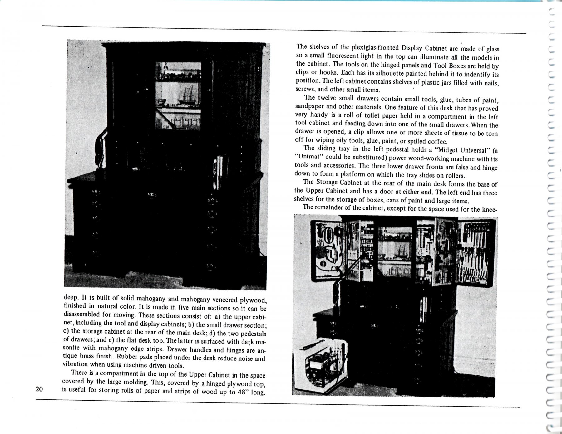
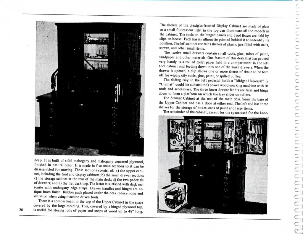
Hi Marc - Welcome to the Borough of Churches. The new hip, lively, foodie - affordable - alternative to the concrete canyons. Best of all, we get to have a view of the skyline of Manhattan, while they only get to look at Brooklyn! That looks like a perfect place to work on and display the SR while in the shipyard. The work done on the bow joinder is excellent as well, and the wooden trompe l'eoil effect is very realistic. I wonder, though, about the raised fleur de lis on the inside of the gunport lids. I don't recall seeing them there in any illustrations, although my depth of knowledge does not match yours. If they were there, wouldn't they be painted, rather than being a carving that would be frequently bumped and damaged by the cannon muzzle? As for a workshop in a small apartment, read through Chapter 3 in Ship Modelers' Shop Notes (vol. 1) for some tips from modelers who did great work on a card table or small desk. There is even a long article about building a dedicated custom cabinet with doors and drawers and cubbyholes that house hundreds of tools and supplies. Lewis Britton provided not only photos, but measured scale drawings of all the parts and even his joinery details. I wouldn't expect anyone today to build one, but a modification of an IKEA cabinet might be possible.
- 2,699 replies
-
- 6
-
-
- heller
- soleil royal
- (and 9 more)
-
Hi Michael - Good problem solving there. My solution would have been a lot less elegant than yours. As for the ribs - could you take square section wood and bend it to your curves, then trim to the sided dimensions that you want? It would be time consuming and wasteful of wood, but no Houdini need apply. Dan
-
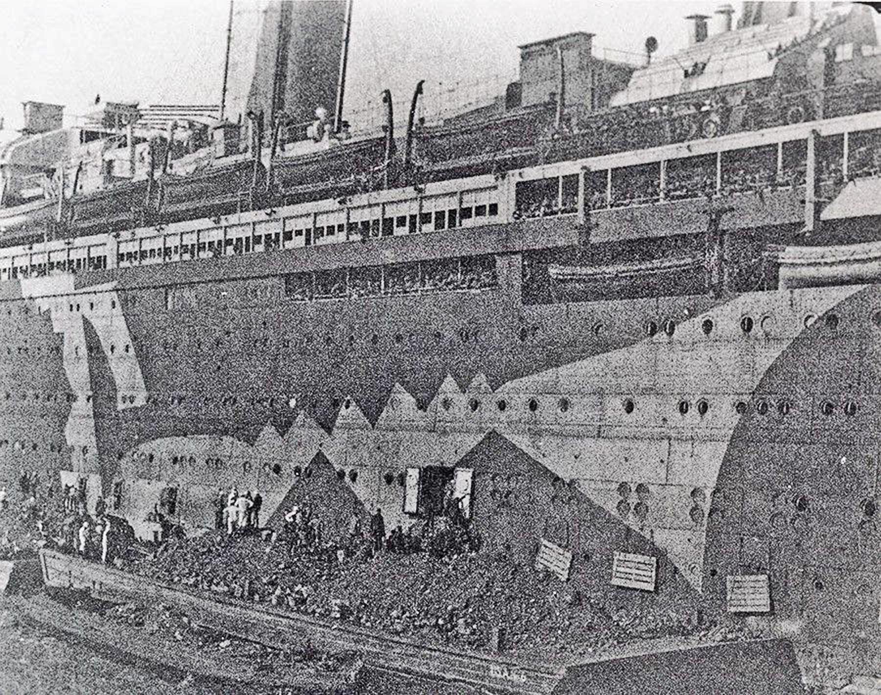
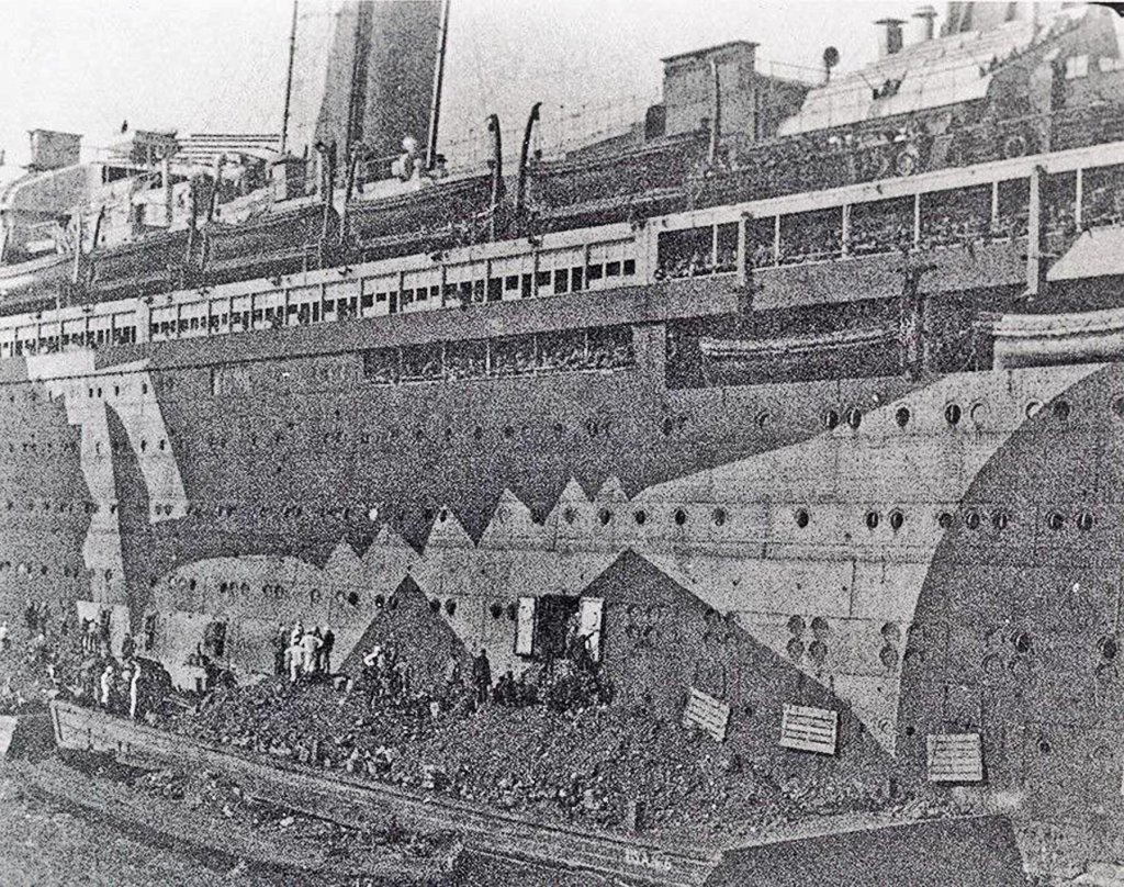
Bob - Forgot to answer your question. I have a photo of the troop ship being loaded with coal, so I presume that the coal-to-oil conversion happened later.
- 238 replies
-
- 6
-
-
- leviathan
- troop ship
- (and 2 more)
-
Hi Roger, Bob - From careful analysis of the photos, it looks like most of the conversions took place from the Vaterland to the troop ship. This included closing off the openings in the third funnel and adding a number of new blowers around the top deck. There was also a very large ventilation unit built on top of the bridge. Lookout posts and a rangefinder platform were built on top of that. Bob is right that the troop ship needed lots of additional air movement. On one trip she carried over 14,000 people at once. After the war the conversion actually reduced the number and size of the vents, as well as modernizing some of the rest. At least that is how I interpret the images. Dan
- 238 replies
-
- 8
-
-
- leviathan
- troop ship
- (and 2 more)
-
Gary, John - Thanks, Now I won't have to redo any blowers. Dan
- 238 replies
-
- 5
-
-
- leviathan
- troop ship
- (and 2 more)